DRAW WIRE SENSOR. Series SX draw wire mechanics for encoder assembly. Content: Key-Features:
|
|
|
- Herbert Todd
- 6 years ago
- Views:
Transcription


1 DRAW WIRE SENSR Series SX draw wire mechanics for encoder assembly Content: Introduction...2 Technical Data...3 Technical Drawing...4 s...5 Encoder Mounting...6 Sensor Mounting...7 Accessories...8 rder Code..10 KeyFeatures: Fast and easy encoder mounting Measurement ranges from 1.0 to 42.5 m Linearity ±0.05% of full range (with encoder) al high corrosion protection Temperature range C (optional 40 C) High dynamics Customised versions available


2 2 INTRDUCTIN WayCon Positionsmesstechnik GmbH is a manufacturer of high quality draw wire position sensors for industrial use. Due to its small overall size, its short assembly time and its possible customisation, the SX sensor technology is a costeffective and flexible solution for a wide range of industrial applications. The dynamics of the draw wire transducer allows a high motion speed and acceleration of the measuring target. Its rugged design and high quality makes applications in harsh industrial environments possible. Special instruments are available with mounting service of encoder on site, as well as customised versions of housing. Sensor principle: The key component of a draw wire sensor is a highly flexible steel wire rope, that is winded singlelayered on an ultra light capstan. This capstan is connected to the sensor housing by a prestressed spring. The end of the steel wire rope, that is equipped with a rope clip gets connected to the target object. As soon as the distance between sensor and target object changes, the steel wire rope gets pulled out of the sensor and is rolled off the capstan (or vice versa). The shaft of the capstan is connected to a potentiometer (for analog output signals), or to an encoder (for digital output signals). If there is a rotation of the capstan due to a change in the distance to the target object, the sensor element will turn proportionally. This way the potentiometer, or the encoder converts a linear movement into a proportional electrical signal. If a standard analog output signal, like V or ma is needed, the sensor is equipped with an additional electronics. rotating shaft sensor element: potentiometer measuring rope rope capstan example: SX50 tension spring electronics: converts the potentiometer output into an analog output SPECIAL FEATURES easy rope fixation with rope clip ball bearing drill protection flexible and shielded sensor cable measuring rope (stainless steel) M12connector system or cable output bushing anodised aluminium housing waterproof housing IP65 or IP67 dynamic spring drive with PA6 case for high displacement speed 2 ball bearings high linearity quick and easy mounting WARNING NTICES Don t let the rope snap back. If the rope is retracted freely, this may lead to injuries (whiplash effect) and the device may be damaged. Caution when unhooking and retracting the rope into the sensor. Never exceed the specified measurement range when extracting the rope! Do not try to open the device. The stored energy of the spring drive may lead to injuries when being mishandled. Do not touch the rope when operating the sensor. Avoid guiding the rope over edges or corners. Use a deflection pulley instead. Do not operate the sensor if the rope is buckled or damaged. A ripping of the rope may lead to injuries or a damaging of the sensor.
3 3 TECHNICAL DATA SX80 Measurement range [mm] Linearity ±[%] 0.05 (with encoder output) Disc circumf erence [mm] 200 Temperature [ C] standard: / optional: (please pay attention to maximum permitted encoder temperature) Weight [g] 700 to 900, depending on the measurement range Housing aluminium, anodised, spring case PA6 Encoder requirements clamping flange (diameter 36 mm), a shaft diameter of 10 mm and a shaft length of mm Accessories cables, connectors, digital display s, def lection pulley, rope extensions, magnetic clamp (see pages 9 and 10) Measurement range [mm] Extraction Force F min [N] Extraction Force F max [N] Speed V max [m/s] Acceleration a max [m/s²] TECHNICAL DATA SX120 Measurement range [mm] Linearity ±[%] 0.05 (with encoder output) Disc circumf erence [mm] Temperature [ C] standard: / optional: (please pay attention to maximum permitted encoder temperature) Lif e expectancy approx. 2 million f ull strokes (dependent on the displacement speed) Weight [g] 1300 to 1600, depending on the measurement range Housing aluminium, anodised, spring case PA6 Encoder requirements clamping flange (diameter 36 mm), a shaft diameter of 10 mm and a shaft length of mm Accessories cables, connectors, digital display s, def lection pulley, rope extensions, magnetic clamp (see pages 9 and 10) Measurement range [mm] Extraction Force F min [N] Extraction Force F max [N] Speed V max [m/s] Acceleration a max [m/s²] TECHNICAL DATA SX135 Measurement range [m] Linearity ±[%] 0.05 (with encoder output) Disc circumf erence [mm] Temperature [ C] standard: / optional: (please pay attention to maximum permitted encoder temperature) Lif e expectancy approx. 2 million full strokes (dependent on the displacement speed) Weight [g] 3200 to 5000, depending on the measurement range Housing aluminium, anodised, spring case PA6 Encoder requirements clamping flange (diameter 36 mm), a shaft diameter of 10 mm and a shaft length of mm Accessories cables, connectors, digital display s, def lection pulley, rope extensions, magnetic clamp (see pages 9 and 10) Measurement range [mm] Extraction Force F min [N] Extraction Force F max [N] Speed V max [m/s] Acceleration a max [m/s²] / / 42,


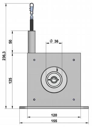
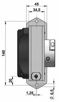
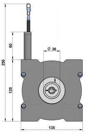

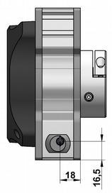
4 4 TECHNICAL DRAWING SX80 SX120 SX135


5 5 INSTALLATIN Mount the sensor at the designated place by using the fixing holes before extracting the rope and before attaching the rope to the measuring target. pen the rope clip after the sensor is fully mounted and extract the measuring rope. Hook the rope clip on the measuring object and close the bracket of the clip. For safety reasons put a screw driver trough the clip to extract the rope. Check the track of the measuring target on collision with the sensor housing and on exceeding the specified measurement range. When installing the sensor make sure that the rubber stopper does not touch the rope outlet. Connect the electronics according to the sensor type. When laying the cables be careful not to underrun the minimal allowed bending radius of the cable (5 x cable diameter). The rope must be extracted from the sensor vertically. The maximum variation from the vertical is 3. Avoid carefully extracting the rope at an inclination, since the durability of the instrument would shorten considerably. If it is not possible to keep the limit of 3, a deflection pulley has to be used. The measuring range begins after approximately 2 mm extracted rope (=zero point). The mechanical reserve at the end of the measuring range is about 20 mm. When mounting outdoors protect the sensor and the rope from icing at temperatures below 0 C. Guide the rope preferably in corners or guarded in channels to prevent pollution or accidental touch. When operating the sensor, take care not to let the rope snap back by mistake or extract the rope over the specified measurement range, as this might destroy the sensor. Maintenance: These instruments are maintenancefree. If however, the rope is soiled due to adverse environmental conditions, it can be cleaned with a cloth drenched in resinfree machine oil. PTINS rder code Corrosion protection CP (e. g. sea water) with a hard ceramicslike layer. Increased temperature range Low Special components and a low temperature grease make a working temperature down to 40 C (up to +85 C) possible. Rope fixation by thread al, pivoted rope fixation Includes a V4A wire rope, stainless steel bearings and option. The sensors rope drum gets HARTCAT coated. This coating is a hardanodic oxidation that protects the sensor from corrosion by aggressive media with screw thread, length 22 mm. Ideal for attachment to through holes or thread holes. rope clip with drill protection (standard) optional rope fixation Ring eye The end of the wire rope is equipped with a ring ey e instead of a rope clip. Inside diameter 20 mm


 the inner radial screw with a 2.")


.")

6 6 Befestigungsmöglichkeiten SX80, SX120, SX1358 ENCDER ASSEMBLY 1. Please insert the encoder into the clamping flange. 2. The encoder is now connected to the clamping flange. 3. By tightening (approx. 2 Nm) the inner radial screw with a 2.5 mm hex wrench the encoder shaft will be clamped to the sensor mechanics and secured from twisting. 4. By tightening (approx. 2 Nm) the outer radial screw with a 2.5 mm hex wrench the encoder housing will be clamped to the sensor housing and secured from twisting. The system is now ready to be used. Befestigungsmöglichkeiten SX135 ENCDER ASSEMBLY BY EASYCLAMPMECHANISM IMPRTANT: All incremental and absolute encoders must have a clamping flange (diameter 36 mm), a shaft diameter of 10 mm and a shaft length of 1020 mm. 1. Please mount the included coupling (1) on the shaft of the encoder and fix the set screw (1.0 Nm). Therefore you will need a hexagon screwdriver, size 2. Please pay attention that the dimension between contact surface of the encoder and the end of the cylinder bolt is 35 mm. 2. Please mount the encoder into the easyclampflange. The cylinder bolt must slip into the spring (2). 3. By tightening (1.5 Nm) the radial screw the encoder will be clamped and secured from twisting. Please use a hexagon screwdriver, size 3. (1) (2)
.")


7 7 SX80, SX120 MUNTING PTINS SX80, SX120: standard rope outlet, rope outlet sideways top (S1) The sensor is usually installed by using the regular mounting plate (see technical drawing on page 4). By disassembling the mounting plate, there are 4 threads (2 x M3, 2 x M5) in the sensor housing for alternative installation. SX80: rope outlet sideways bottom (S2), rope outlet bottom (S3) Sensors with option rope outlet S2 and S3 have a modified base plate. SX120 rope outlet sideways bottom (S2), rope outlet bottom (S3) Sensors with option rope outlet S2 and S3 have a modified base plate. SX135 MUNTING PTINS 1. by using the grooves in the sensor housing The included Tslot nuts can be easily inserted into the grooves of the sensor housing. The nuts have a metric thread M6. Each sensor up to 20 m measurement range comes with 2 nuts, from 20 to 42.5 m four nuts are included. 2. by angle clamp brackets The angle clamp brackets feature a bore for M6 screws to fix it on a plate/ slab or a profile. Each sensor up to 20 m measurement range comes with 2 brackets, from 20 to 42.5 m four brackets are included. 2 Important: The grooves of the sensor housing, the nuts and brackets are compatible to the aluminium building kit system from item Industrietechnik GmbH ( 1 Position of the grooves: Mounting by using brackets:


 SV2XXXX: rope extension (5000...19995 mm) SV3XXXX: rope extension (20000.")
8 8 ACCESSES Deflection pulley UR2 The rope must be extracted from the sensor vertically. The maximum variation from the vertical is 3. A deflection pulley allows a change in the direction of the wire rope. Several pulleys may be used. The rope clip must not be guided over the deflection pulley. material: anodised aluminium, PM mounting: by 2 hexagon socket or countersunk screws M6, vertical or horizontal mounting possible. Ball bearings: with special low temperature grease and RSsealing. Temperature: C. Rope extension SV For bridging a greater distance between the measuring target and the sensor a rope extension can be applied. The rope clip must not be guided over the deflection pulley. Please specify the length needed in your order (XXXX). The minimum length is 150 mm: SV1XXXX: rope extension ( mm) SV2XXXX: rope extension ( mm) SV3XXXX: rope extension ( mm) Magnetic clamp MGG1 Use the magnetic clamp to quickly attach the rope to metallic objects without any assembly time. A rubber coating provides gentle contact (e. g. on varnished surfaces) and prevents from slipping due to vibration. The magnet consists of a neodym core for an increased adhesive force of 260 N. The hook makes it easy to attach the rope clip.
9 9 ACCESSES DIGITAL UTPUT INCREMENTAL Cable with connector M12, 8 poles, shielded Mating connector M12, 8 poles, shielded Mating connector M23, 12 poles K8P2MSM12 2 m, connector straight D8GM12S mating connector straight CN012S straight, metal housing K8P5MSM12 5 m, connector straight D8WM12S mating connector angular wire diameter: AWG mm² K8P10MSM12 10 m, connector straight protection class: IP67 cable diameter: ø mm K8P2MSWM12 2 m, connector angular temperature: C K8P5MSWM12 5 m, connector angular cable passage: ø mm K8P10MSWM12 10 m, connector angular wire diameter: mm² CN012S Digital distance and speed display WAYD for incremental output signals Use the WAYD display to visualise the measured distance or the speed (tachometer) of the position transducer. A transfer of data to a PC or PLC can be done with the RS232 interface of the WAYDR. Protection class: IP65 (front panel) Display: 6 digits Supply: 115 / 250 VAC utput Linedriver L (TTL, RS422): WAYDS5VH: WAYDG5VH: WAYDR5VH: display only, input level TTL display with two presets and switching outputs, input level TTL display with serial interface RS232 / RS485, input level TTL utput PushPull G: WAYDS: WAYDG: WAYDR: display only, input level HTL display with two presets and switching outputs, input level HTL display with serial interface RS232 / RS485, input level HTL For further information please see the WAYD data sheet. ACCESSES DIGITAL UTPUT ABSLUTE SSI output: CANopen output: K12P02MSM23SSI K12P05MSM23SSI K12P10MSM23SSI K12P15MSM23SSI 2 m cable, shielded, M23 connector straight K5P2MBM12CAN 2 m cable, plug f emale M12, 5 poles, open ends 5 m cable, shielded, M23 connector straight K5P2MSBM12CAN 2 m cable, connector male M12, 5 poles, plug f emale M12 10 m cable, shielded, M23 connector straight K5P2MSM12CAN 2 m cable, connector male, M12, 5 poles, open ends 15 m cable, shielded, M23 connector straight EtherCAT / Profinet: CN012S Mating connector M23 shielded, straight, 12 poles K4P2MSM12CAT 2 m cable, connector male M12, 4 poles, open ends Profibus DP: K4P5MSM12CAT 5 m cable, connector male M12, 4 poles, open ends K5P2MBM12PRF 2 m cable, plug f emale M12, 5 poles, open ends K4P10MSM12CAT 10 m cable, connector male M12, 4 poles, open ends K5P2MSBM12PRF 2 m cable, connector male M12, 5 poles, plug f emale M12 K4P2MSSM12CAT 2 m cable, connector male M12 on both ends, 4 poles K5P2MSM12PRF 2 m cable, connector male, M12, 5 poles, open ends K4P5MSSM12CAT 5 m cable, connector male M12 on both ends, 4 poles M12PRFAW terminator K4P10MSSM12CAT 10 m cable, connector male M12 on both ends, 4 poles Digital distance and speed display WAYSSI for SSI output signals Use the WAYSSI display to visualise the measured distance or the speed (tachometer) of the position transducer. A transfer of data to a PC or PLC can be done with the RS232 interface of the WAYSSIR. Protection class: IP65 (front panel) Display: 6 digits Supply: 115 / 250 VAC WAYSSIS: WAYSSIA: WAYSSIG: WAYSSIR: display only display with analog output display with two presets and switching outputs display with serial interface RS232 / RS485 For further information please see the WAYSSI data sheet.
10 10 SX80 RDER CDE DRAW WIRE MECHANICS SX80 F58NK Measurement range [mm] 1000 / 1500 / 2000 / 2500 / 3000 S1 S2 S3 rope fixation be thread synthetic wire rope, made out of Coramid rope outlet sideways top rope outlet sideways bottom rope outlet bottom increased temperature range low C corrosion protection SX80 ranges 2500/3000 mm, SX120 RDER CDE DRAW WIRE MECHANICS SX120 F58NK Measurement range [mm] 3125 / 4000 / 5000 S1 S2 S3 rope fixation be thread synthetic wire rope, made out of Coramid rope outlet sideways top rope outlet sideways bottom rope outlet bottom increased temperature range low C corrosion protection SX120, SX135 UP T 8.0 M RDER CDE DRAW WIRE MECHANICS SX135 F58NK Measurement range [m] 6 / 7 / 8 rope fixation be thread synthetic wire rope, made out of Coramid increased temperature range low C corrosion protection SX1356/7/8 ranges 7 / 8 m,
11 11 SX80 RDER CDE DRAW WIRE MECHANICS SX80 F58NK Measurement range [mm] 1000 / 1500 / 2000 / 2500 / 3000 S1 S2 S3 rope fixation be thread synthetic wire rope, made out of Coramid rope outlet sideways top rope outlet sideways bottom rope outlet bottom increased temperature range low C corrosion protection SX80 ranges 2500/3000 mm, SX120 RDER CDE DRAW WIRE MECHANICS SX120 F58NK Measurement range [mm] 3125 / 4000 / 5000 S1 S2 S3 rope fixation be thread synthetic wire rope, made out of Coramid rope outlet sideways top rope outlet sideways bottom rope outlet bottom increased temperature range low C corrosion protection SX120, SX135 UP T 8.0 M RDER CDE DRAW WIRE MECHANICS SX135 F58NK Measurement range [m] 6 / 7 / 8 rope fixation be thread synthetic wire rope, made out of Coramid increased temperature range low C corrosion protection SX1356/7/8 ranges 7 / 8 m,
12 12 SX M AND GREATER RDER CDE DRAW WIRE MECHANICS SX135 F58K Measurement range [m] 10 / 12 / 15 / 20 / 25 / 30 / 35 / 40 / 42.5 CP(135) rope fixation be thread increased temperature range low C corrosion protection SX135 CP(135) CP(135) CP(135), GENERAL ACCESSES UR2 Def lection pulley SV1XXXX rope extension ( mm) MGG1 Magnetic clamp SV2XXXX rope extension ( mm) SV3XXXX rope extension ( mm) Subject to change without prior notice. WayCon Positionsmesstechnik GmbH info@waycon.de internet: Head ffice Mehlbeerenstr Taufkirchen Tel. +49 (0) Fax +49 (0) ffice Köln Auf der Pehle Brühl Tel. +49 (0) Fax +49 (0)
Draw-wire system SZG165
 Draw-wire system SZG165 www.wachendorff-automation.com Wachendorff Automation... systems and encoders Complete systems Industrial rugged encoders to suit your application Standard range and customer versions
INSTALLATION GUIDE FIRST STEPS MOUNTING OF THE SENSOR HANDLING THE WIRE ROPE
 INSTALLATION GUIDE Draw wire sensors series SX0, SX80, SX0 For further information please see the data sheet at www.waycon.biz/products/draw-wire-sensors FIRST STEPS WayCon Positionsmesstechnik GmbH would
Inductive Linear Displacement Transducers Model IW 260 Measuring strokes: 80 mm, 170 mm, 240 mm, 360 mm
 Inductive Linear Displacement Transducers Model IW 260 Measuring strokes 80, 170, 240, 360 Document no. IW 100 HE Date 1.07.201 Contactless, robust sensor system Infinite resolution, no hysteresis Calibrated
CFSW. Hinges with built-in safety multiple switch
 CFSW. Hinges with built-in safety multiple switch ELESA Original design Elesa Standards Main dimensions Fitting Weight Code Description L B f ±0.2 f 1 ±0.2 H h 1 h 2 d 3 d 4 C [Nm]# g 426601 CFSW.110-6-2NO+2NC-C-A
Hoisting Equipment Cable puller & Accessories
 Yale hoists and trolleys are not ed for Cable puller model Yaletrac Pulling force 800-3200 It has a light weight, compact, high tensile aluminium alloy housing with a large flat bottom surface for increased
INSTALLATION INSTRUCTIONS
 INSTALLATION INSTRUCTIONS HIGH PRESSURE PUMP To minimize vibration, it is best to build brackets on the motor itself, similar to alternator brackets. Use cardboard to construct a pattern first before making
Depth sensor. Product reference : REV 1. USER GUIDE and INSTALLATION GUIDE. nke Sailing competition
 Depth sensor Product reference : 90-60-456 REV 1 USER GUIDE and INSTALLATION GUIDE nke Sailing competition Z.I. Kerandré Rue Gutenberg 56700 HENNEBONT- FRANCE http://www.nke.fr After sale service n 33
CFSW. Hinges with built-in safety multiple switch
 CFSW. Hinges with built-in safety multiple switch ELESA Original design technical informations Material - Hinge body: self-extinguish high-rigidity SUPER-technopolymer, black colour. Resistant to solvents,
PURA. Pure Gas Dewpoint Transmitter. Users Guide
 PURA Pure Gas Dewpoint Transmitter Users Guide Issue January 2003 Page 2 Table of Contents SECTION PAGE 1 Product Overview 3 2 Preparation 3 3 Installation 3 3.1 PURA Premium & OEM Dewpoint Transmitter
Operating instructions Safety Rope Emergency Stop Switches ZB0052 / ZB0053 ZB0072 / ZB0073
 Operating instructions Safety Rope Emergency Stop Switches UK ZB0052 / ZB0053 ZB0072 / ZB0073 7390878 / 02 03 / 2011 Contents 1 Safety instructions...3 2 Installation / set-up...4 2.1 Applications...4
ARI-DP32 / DP33 / DP34 / DP34T / DP34Tri / DP35 Pneumatic actuator ARI-DP
 ARI-DP32 / DP33 / DP34 / DP34T / DP34Tri / DP35 ARI-DP32 / DP33 Pneumatic actuator Page 2 DP-Actuator Extended stem on air failure ARI-DP34 Pneumatic actuator Page 2 ARI-DP34T Pneumatic actuator Page 6
![[Instruments for vacuum measurement, checking and adjustment] 3](/thumbs/94/121874202.jpg "[Instruments for vacuum measurement, checking and adjustment] 3")
C-Flow Coriolis Mass Flow Meters
 Coriolis Mass Flow Meters Ready for Take Off The New Compact C-Flow Küppers Elektromechanik GmbH The C-Flow The C-Flow Coriolis Mass Meters consist of two components: KCE Transmitter KCM Transducer 2 KEM
Prewired position switches FA series
 2 Prewired position switches FA series Selection diagram 01 08 10 11 1 15 1 02 external rubber gasket external rubber gasket 1 51 52 54 55 56 5 ACTUATORS adjustable lever safety adjustable lever 41 45
Supplementary instructions. Rod and cable components. for VEGAFLEX series 80. Document ID: 44968
 Supplementary instructions Rod and cable components for VEGAFEX series 80 Document ID: 44968 Contents Contents 1 Product description 1.1 Extensions... 3 2 Mounting 2.1 General instructions... 6 2.2 Rod
Expansion Thermometers Stainless Steel Series, Model 70
 Mechanical Temperature Measurement Expansion Thermometers Stainless Steel Series, Model 70 WIKA Data Sheet TM 81.01 Applications General-purpose temperature measuring instruments for gaseous, liquid and
LK-SX VOC. Application. Security Advice Caution. Notes on Disposal. Combined sensor mixed gas. Data sheet
 LK-SX VOC Combined sensor mixed gas Data sheet Subject to technical alteration Issue date: 24.08.2015 Application The sensor detects air quality in ventilation ducts. A stronger output signal of the sensor
pneumatic power clamps
 pneumatic power clamps Features Király Trading KFT H-1151 Budapest Mogyoród útja 12-14 E-mail:_agi@kiralytrading.hu Your requirements Power element of machines, tools and devices for the following applications:
TECHNICAL INFORMATION
 TECHNICAL INFORMATION Models No. TD0101, TD0101F Description Impact Driver L PRODUCT P 1/ 14 CONCEPT AND MAIN APPLICATIONS Models TD0101 and TD0101F are cost-competitive 100N.m-class impact driver developed
Preferred Instruments Danbury, CT USA
 Tank Level Sensor Model TG-EL-WF-xx Installation & Operation Instructions SDI-TG-EL-WF March 6, 2006 Preferred Instruments Danbury, CT USA www.preferredinstruments.com CONTENTS Installation Pg. 2 Calibration
AMS 2710 PCB pressure sensor module with V output
 FEATURES Universal pressure sensor module with 0.. 10 V voltage output Fully calibrated and temperature compensated sensor module Variants for (bidirectional) differential, gage, absolute and barometric
Deluxe Gourd Racks I D E G A. Parts List. Shown above are parts for the two-level, Deluxe Gourd Rack (DGR 12V)with 12 arms for vertically hung gourds.
with 12 arms for vertically hung gourds.") Deluxe Gourd Racks H F K I D E J C G A Shown above are parts for the two-level, Deluxe Gourd Rack (DGR V)with arms for vertically hung gourds. Parts List Code Quantity A B C D E F G H I J 6, or 4 6, or
Deluxe Gourd Racks H F K I D E J C G A Shown above are parts for the two-level, Deluxe Gourd Rack (DGR V)with arms for vertically hung gourds. Parts List Code Quantity A B C D E F G H I J 6, or 4 6, or
INSTRUCTION MANUAL. January 23, 2003, Revision 0
 INSTRUCTION MANUAL Model 810A In-Vitro Test Apparatus for 310B Muscle Lever January 23, 2003, Revision 0 Copyright 2003 Aurora Scientific Inc. Aurora Scientific Inc. 360 Industrial Parkway S., Unit 4 Aurora,
User Manual V14.1 IP68 LED FLEX NEON
 User Manual V14.1 IP68 LED FLEX NEON PLEASE READ THESE INSTRUCTIONS CAREFULLY BEFORE INSTALLATION LEAVE A COPY FOR THE END USER/MAINTENANCE ENGINEER FOR FUTURE REFERENCE 1/11 PRODUCT SPECIFICATION 1. Operating
Data sheet Pressure switch type CS December 2001 DKACT.PD.P10.A B1119
 Pressure switch type CS December 2001 DKACT.PD.P10.A2.02 520B1119 Introduction Pressure switch type CS is part of the Danfoss pressure control range. All CS pressure switches have a built-in pressure-operated,
Flow VA 520. incl. temperature measurement. Intelligent solutions for ac- for compressed air and gases R 1/4 (DN 8) DN 15 R 3/4 (DN 20) DN 25
 DN 15 R 3/4 (DN 20) DN 25") VA 520 incl. temperature R 1/4 (DN 8) DN 15 R 3/4 (DN 20) DN 25 R 1 1/4 (DN 32) DN 40 R 2 (DN 50) Intelligent solutions for ac- for compressed air and gases work according to the approved calorimetric
VA 520 incl. temperature R 1/4 (DN 8) DN 15 R 3/4 (DN 20) DN 25 R 1 1/4 (DN 32) DN 40 R 2 (DN 50) Intelligent solutions for ac- for compressed air and gases work according to the approved calorimetric
SERIES 2 RAMP OWNER S MANUAL TOOLS REQUIRED: BEFORE YOU BEGIN... Read and understand these instructions before beginning a ramp setup.
 SERIES 2 RAMP OWNER S MANUAL BEFORE YOU BEGIN... Read and understand these instructions before beginning a ramp setup. Use caution and care for your back when lifting, pushing, pulling, folding or unfolding
MODEL ANALOG ALTIMETER USER'S MANUAL 330KHZ, 1000M DEPTH RATED 0.2 TO 100FT OPERATING RANGE ANALOG OUTPUT
 MODEL 862-000-200 ANALOG ALTIMETER USER'S MANUAL 330KHZ, 1000M DEPTH RATED 0.2 TO 100FT OPERATING RANGE ANALOG OUTPUT DOCUMENT NO. 430-007H September 20, 2005 S/N IMAGENEX TECHNOLOGY CORP. 209-1875 BROADWAY
Boat Boat Loader Fitting Instructions
 Aerodynamic & Heavy Duty Roof Rack Systems Australian Made - Australian Owned www.rhinorack.com Boat Boat Loader Fitting Instructions CONTROLLED Balance point 3 Front eye nuts position 3 Transom eye nut
Flow controller Type ED/CCB311 Instruction manual
 Flow measurement Flow controller Type ED/CCB311 1. GENERAL DESCRIPTION page 4 2. DETAILED DESCRIPTION page 4 3. PIPE - EXPLOITATION page 5 4. PREVENTIVE MAINTENANCE page 5 5. REPLACEMENT OF THE CONTACT
Vortex Flow Sensor VA Di Ex-d for flow measurement in gases; with integrated, configurable transducer UVA in Ex-d housing
 Vortex Flow Sensor VA Di Ex-d Vortex Flow Sensor VA Di Ex-d for flow measurement in gases; with integrated, configurable transducer UVA in Ex-d housing Drawing 1 Measurable variables actual flow rate actual
Mass Flow Controller (MFC) for Gases
 for Gases") Mass Flow Controller (MFC) for Gases Bypass MFC with capillary technology for nominal flow rates from 5 ml N /min to 15 l N /min Applicable for aggressive gases Compact design and digital communication
Mass Flow Controller (MFC) for Gases Bypass MFC with capillary technology for nominal flow rates from 5 ml N /min to 15 l N /min Applicable for aggressive gases Compact design and digital communication
Instruction Manual Differential Pressure Transmitter
 DE13 Instruction Manual Differential Pressure Transmitter Table of Contents 1. Safety Instructions 2. Intended Applications 3. Product Description and Functions 4. Installation 5. Commissioning 6. Maintenance
Level transmitter LT 100
 KROHNE 09/2001 7.02363.21.00 GR/PRINTO Level transmitter LT 100 Status: 10/99 Variable area flowmeters Vortex flowmeters Flow controllers Electromagnetic flowmeters Ultrasonic flowmeters Mass flowmeters
Analogue and Digital Mass Flow Meters and Controllers for Gases MASS-STREAM
 Analogue and Digital Mass Flow Meters and Controllers for Gases MASS-STREAM M+W Instruments Your partner Key Facts M+W Instruments was founded in 1988 and has always specialised in thermal mass flow meters
MPG-plus. Application example. Pneumatic 2-Finger Parallel Gripper Gripper for small components. Gripping force 38 N 175 N. Sizes
 MPG-plus Sizes 25 40 Weight 0.06 kg 0.24 kg Gripping force 38 N 175 N Stroke per finger 3 mm 6 mm Workpiece weight 0.19 kg 0.7 kg Application example Pneumatically driven, dual-axis pick-and-place machine
LK-SX CO 2 +VOC. Application. Security Advice Caution. Notes on Disposal
 LK-SX CO 2 +VOC Sensor for detection of carbon dioxide (CO 2) and mixed gas content in air ducts Data sheet Subject to technical alteration Issue date: 24.08.2015 Application For detection of CO2 and VOC.
Mass Flow Controller (MFC) for Gases
 for Gases") Mass Flow Controller (MFC) for Gases Bypass MFC with capillary technology for nominal flow rates from ml N /min to 0 l N /min Applicable for aggressive gases Fieldbus option Type 870 can be combined with...
Mass Flow Controller (MFC) for Gases Bypass MFC with capillary technology for nominal flow rates from ml N /min to 0 l N /min Applicable for aggressive gases Fieldbus option Type 870 can be combined with...
Infrared Linescanners
 Thermal Imaging and Temperature Profiles for Continuous Process Monitoring and Quality Control HD Infrared Linescanners PROCESS & ANALYTICAL INSTRUMENTS Mountings and Accessories LSPHD Mountings and Accessories
TECHNICAL INFORMATION
 TECHNICAL INFORMATION Model No. Description RP2300FC, RP2301FC Router CONCEPT AND MAIN APPLICATIONS Models RP2300FC and RP2301FC are upgraded sister tools of our current plunge-type electronic router Model
better measurement Simply a question of SCHMIDT Flow Sensor SS The cost-effective alternative in pressurised systems up to 10 bars.
 Simply a question of better measurement SCHMIDT Flow Sensor SS 20.261 The cost-effective alternative in pressurised systems up to 10 bars. Compressed air technology Industrial processes A cost analysis
Certified according to DIN EN ISO 9001 Technical Datasheet TRICOR Series Mass Flow Meters
 www.kem-kueppers.com info@kem-kueppers.com Certified according to DIN EN ISO 9001 Technical Datasheet TRICOR Series Mass Flow Meters Description The Tricor Mass Flow Meters measure simultaneously mass
Manual winch MANISTOR 100 and 200
 Manual wall winch Manual winch MANISTOR 100 and 200 Instruction manual UK 173-192.10-3 PRODUCT DEVELOPED AND MANUFACTURED ACCORDING TO NF EN 13157 STANDARD REGISTERED DESIGN To ensure the constant improvement
Pneumatic spool valve islands
 Pneumatic spool valve islands P7.GB.R MEGA SPOOL VALVE ISLANDS MEGA pneumatic spool valve islands offer maximum performance along with flexibility, easy installation and simple operation. Due to their
Mass Flow Meter (MFM) for gases
 for gases") Mass Flow Meter (MFM) for gases Type can be combined with Inline MFM for nominal flow rates from 25 l N /min to 1,500 l N /min; 1/4 to 3/4 High accuracy Fast settling time Fieldbus option Special version
Mass Flow Meter (MFM) for gases Type can be combined with Inline MFM for nominal flow rates from 25 l N /min to 1,500 l N /min; 1/4 to 3/4 High accuracy Fast settling time Fieldbus option Special version
DPS-400 SERIES DPH-100 SERIES
 745 Dual Display Digital Pressure Sensor For Gas DPS-400 SERIES SERIES General terms and conditions... F- guide... P.699~ Related Information Glossary of terms... P.156~ General precautions... P.1566 PHOTO
Target disk flowmeter Series DP. Instructions manual DP65 DP500. R-MI-DP Rev.: 4 English version
 Target disk flowmeter Series DP Instructions manual DP65 DP500 R-MI-DP Rev.: 4 English version PREFACE Thank you for choosing the flowmeter series DP from Tecfluid S.A. This instruction manual allows the
TRAVSMART permanent single-cable horizontal lifeline system
 The Travsmart single-line system provides a smooth travel. It allows the traveler to move freely over the intermediate anchors, minimizing wear and eliminating user assistance. The user s hands remain
10.2. Basketball Single Post System
 Basketball Basketball Single Post System The single-post basketball stand is made with oval aluminium profiles with a cross-section of 120 x 100 mm. The wall thickness of this robust apparatus is 4 to
Components for air preparation and pressure adjustment. OUT port position ( ) connected Rear side. of IN port. Air tank. directly.
 connected Rear side. of IN port. Air tank. directly.") Components preparation and pressure adjustment ABP Overview ABP is a component that enables boosting by s only up to twice primary pressure (.0MPa max.) in combination with using air tank but not using
Components preparation and pressure adjustment ABP Overview ABP is a component that enables boosting by s only up to twice primary pressure (.0MPa max.) in combination with using air tank but not using
GWB Pneumatic 2-Finger Radial Gripper Universal Gripper Sizes Weight Gripping moment Opening angle per finger Workpiece weight
 GWB Sizes 34.. 100 Weight 0.14 kg.. 3.5 kg Gripping moment 2.1 Nm.. 127 Nm Opening angle per finger 10.. 90 Workpiece weight 0.3 kg.. 6.0 kg Application example Rotating/gripping combination for handling
Pressure Dump Valve Service Kit for Series 2300 Units
 Instruction Sheet Pressure Dump Valve Service Kit for Series 00 Units. Overview The Nordson pressure dump valve is used to relieve hydraulic pressure instantly in Series 00 applicator tanks when the unit
Order No Projection Backboard
 Basketball Basketball Single Post System The single-post basketball stand is made with oval aluminium profiles with a cross-section of 120 x 100 mm. The wall thickness of this robust apparatus is 4 to
CHAPTER 5 REWIND STARTERS
 GENERAL INFORMATION CHAPTER 5 REWIND S Rewind starters used on vertical shaft Tecumseh engines are top mount horizontal pull style or side mount vertical pull style. Horizontal shaft engines use side mounted
MODEL DIGITAL ALTIMETER USER'S MANUAL 330KHZ, 1000M DEPTH RATED 0.5 TO 100FT (0.15 TO 30M) OPERATING RANGE SERIAL OUTPUT
 OPERATING RANGE SERIAL OUTPUT") MODEL 863-000-200 DIGITAL ALTIMETER USER'S MANUAL 330KHZ, 1000M DEPTH RATED 0.5 TO 100FT (0.15 TO 30M) OPERATING RANGE SERIAL OUTPUT DOCUMENT NO. 430-017C April 14, 2005 S/N IMAGENEX TECHNOLOGY CORP. 209-1875
MODEL 863-000-200 DIGITAL ALTIMETER USER'S MANUAL 330KHZ, 1000M DEPTH RATED 0.5 TO 100FT (0.15 TO 30M) OPERATING RANGE SERIAL OUTPUT DOCUMENT NO. 430-017C April 14, 2005 S/N IMAGENEX TECHNOLOGY CORP. 209-1875
K13.12 FACE FIXED PANIC EXIT DEVICE K13 DOORS
 K13 DOORS K13.12 FACE FIXED PANIC EXIT DEVICE 01.03.2018 Waregemstraat 5-9870 Zulte - Belgium - T. +32 9 388 88 81 - F. +32 9 388 88 21 - commercial@sobinco.com - www.sobinco.com CONTENTS 1. Base set n
Coiling Tube with Twist-Proof Fitting
 http://www.pisco.co.jp FITTING CONTROLLER VALVE TUBE MAKE-TO-ORDER PRODUCTS Push-In Fitting Type Anti-Twisting Coiling Tube for Air Tool Coiling Tube with Twist-Proof Fitting 306 Avoid Twisted Tube Problem
Pneumatic Gripping Modules. Pneumatic 2-Finger Radial Grippers
 Pneumatic Gripping Modules Pneumatic 2-Finger Radial Grippers Pneumatic Gripping Modules Pneumatic 2-Finger Radial Grippers 2-FINGER RADIAL GRIPPERS Series Size Page Universal Grippers GWB 676 GWB 34 680
MANUAL KPS Pressure Control Valve
 TetraTec Instruments GmbH Gewerbestrasse 8 71144 Steinenbronn Deutschland E-Mail: info@tetratec.de Tel.: 07157/5387-0 Fax: 07157/5387-10 MANUAL Pressure Control Valve *** VERSION 1.0 *** Update: 17.11.2006
Hand lever valves VHER
 Hand lever valves VHER Hand lever valves VHER Key features Powerful Flexible Practical -M- Flow 170 3800 l/min 4/3-way valve mid-position closed mid-position exhausted mid-position pressurised Connections:
PULSAR 5000 SERIES OPERATING & INSTALLATION INSTRUCTIONS SERIES 5000 PLEASE READ CAREFULLY BEFORE INSTALLING
 PULSAR 5000 SERIES OPERATING & INSTALLATION INSTRUCTIONS SERIES 5000 PLEASE READ CAREFULLY BEFORE INSTALLING Please Note: Ranges above 500mbar are designed and manufactured in accordance with sound engineering
SpeciÞcations. Engine Dimensions Dimensions in millimeters. Inch equivalents shown in [].
![SpeciÞcations. Engine Dimensions Dimensions in millimeters. Inch equivalents shown in [].](/thumbs/77/75006228.jpg "SpeciÞcations. Engine Dimensions Dimensions in millimeters. Inch equivalents shown in [].") SpeciÞcations Engine Dimensions Dimensions in millimeters. Inch equivalents shown in []. Ê ßÔ Ê ÛÝ Ñ Ê Û ÎÊ Û É 5 ENGINE IDENTIFICATION NUMBERS Kohler engine identiþcation numbers (model, speciþcation
SpeciÞcations Engine Dimensions Dimensions in millimeters. Inch equivalents shown in []. Ê ßÔ Ê ÛÝ Ñ Ê Û ÎÊ Û É 5 ENGINE IDENTIFICATION NUMBERS Kohler engine identiþcation numbers (model, speciþcation
COMPONENT SPECIFICATION M80-7XX SERIES CONNECTORS - THREE ROW
 COMPONENT SPECIFICATION M80-7XX SERIES CONNECTORS - THREE ROW JUN 200 CONTENTS: SECTION TITLE PAGE Description of Connector and Intended Application 2 2 Marking of Connector and/or Package 2 3 Ratings
Position switches FP series
 A Position switches FP series Selection diagram 0 08 8 9 0 0 0 Ø 8 mm Ø, mm external rubber stainless steel stainless steel fiber glass rod gasket sphere sphere adjustable lever safety adjustable lever
Magnetic level switch type MR783 Instruction Manual
 Magnetic level switch Magnetic level switch type MR783 1. DESCRIPTION page 3 1.1 Operation page 3 1.2 Application page 3 1.3 Description page 3 2. SPECIFICATIONS page 3 2.1 Service Conditions page 4 2.2
Security and confidence at height.
 A Security and confidence at height. Vertical Systems DISTRIBUTED BY M DBI-SALA Vertical Systems are designed to complement your ability to work while meeting all applicable OSHA and ANSI standards. Vertical
Figure 1 - Parts Identification
 Instructions for the following series products: Zorbit Energy Absorber Kits (See back page for specific model numbers.) User Instruction Manual Zorbit Energy Absorber Kits for Horizontal Lifeline Systems
INSTRUCTION MANUAL Pressure Relief Device LPT
 INSTRUCTION MANUAL Pressure Relief Device LPT 5COV475800 LPT REV00 CONTENT: 1 SAFETY 1.1 Safety instructions 2 1.2 Specified applications 2 1.3 Safety notes on the equipment operation 2 2 PRESSURE RELIEF
Sizes Weight Gripping force Stroke per finger Workpiece weight Pieces : kg N mm kg
 MPG-plus Sizes Weight Gripping force Stroke per finger Workpiece weight Pieces : 7 0.06.. 0.63 kg 25.. 350 N 1.5.. 10 mm 0.19.. 1.25 kg Application example Pneumatically driven, dual-axis pick-andplace
Retrofitting Green SkiErg Handles
 Materials Needed 1 replacement cord* 1 Bulldog clip Measuring tape or ruler Scissors *Contains lanolin Procedure Overview Remove the SkiErg from the wall or floor stand Remove cover plates Remove old cord
Instruction Manual AC350 GUIDED-TYPE FALL ARRESTER ON RIGID ANCHORAGE LINE EN 353-1:2002
 GENERAL CONDITIONS OF UTILIZATION 5 6 7 8 9 - should be filled in by competent person and kept during whole period of the system usage. COMISSION AND FIRST USE - after installation of the working rope
Installation Instructions MODEL VSTI-A020 Tank Indicator Installation Model: VSTI-A020, Stainless Reverse Read System Versa Steel Inc. Guide Cables No
 Tank Indicator Installation Model: VSTI-A020, Stainless Reverse Read System Guide Cables No Guide Cables 1 August 4, 2011 Assembly Instructions: (Shown with a 2 board, 12 ft kit) ITEM NO. PART NUMBER DESCRIPTION
Torque Tube TB300 Digital Transmitters
 Page 1 of 7 7E.300-E Issue 4-2009 Description Series TB300 torque tube liquid level instruments utilize the buoyancy exerted on a displacer when immersed in a liquid. The buoyancy on the displacer is proportional
The Limit Switch with Better Seal, Shock Resistance, and Strength. General-purpose Limit Switch. Model Number Structure
 General-purpose Limit Switch CSM_DA-_N_DS_E The Limit Switch with Better Seal, Shock Resistance, and Strength A double seal on the head, a complete gasket cover, and other features ensure a better seal
Saab Seaeye Cougar XT Compact
 The Seaeye Cougar-XT Compact is a highly flexible and extremely powerful electric ROV with working depths of 300 metres. This system comes with almost all of the specifications of the very reliable Couger-XT
PZN-plus. Application example. Pneumatic 3-Finger Centric Gripper Universal Gripper. Sizes Gripping force 580 N..
 PZN-plus Sizes 40.. 300 Weight 0.43 kg.. 43.5 kg Gripping force 580 N.. 38000 N Stroke per finger 3 mm.. 35 mm Workpiece weight 2.9 kg.. 190 kg Application example Insertion tool for assembling small to
Product information. Capacitive. Level detection in liquid VEGACAP 62 VEGACAP 63 VEGACAP 64 VEGACAP 66 VEGACAP 69. Document ID: 29983
 Product information Level detection in liquid VEGACAP 62 VEGACAP 63 VEGACAP 64 VEGACAP 66 VEGACAP 69 Document ID: 29983 Contents Contents 1 Description of the measuring principle... 3 2 Type overview...
Side-of-Pole Mount for 1 Module (SPM1) For Module Types A & B
 For Module Types A & B") Side-of-Pole Mount for 1 Module (SPM1) For Module Types A & B ASSEMBLY INSTRUCTIONS step-by-step assembly and installation Version 1, Rev A PCN 080311-2 SP3363-1 Side-of-Pole Mount for 1 Module (SPM1)
Side-of-Pole Mount for 1 Module (SPM1) For Module Types A & B ASSEMBLY INSTRUCTIONS step-by-step assembly and installation Version 1, Rev A PCN 080311-2 SP3363-1 Side-of-Pole Mount for 1 Module (SPM1)
Rolled Rotary Ball Screw
 51E Rolled Rotary Ball Screw Model BLR End cap Collar Seal Spacer Ball End cap Screw shaft Outer ring Ball screw nut Retainer Outer ring Ball Fig.1 Structure of Large Lead Rotary Nut Ball Screw Model BLR
ATS430 turbidity sensor Retractable insertion assembly
 A MEASUREMENT & ANALYTICS INSTRUCTION ATS430 turbidity sensor Retractable insertion assembly Measurement made easy 1 Introduction This publication details installation procedures for the retractable insertion
2-jaw self-centering pneumatic parallel gripper (series SX)
") SX 2-jaw self-centering pneumatic parallel gripper (series SX) Double acting (normally closed on request). High gripping force. Protection class: IP67. Double O-Ring sealing on the columns. Suitable for
SX 2-jaw self-centering pneumatic parallel gripper (series SX) Double acting (normally closed on request). High gripping force. Protection class: IP67. Double O-Ring sealing on the columns. Suitable for
Hydraulic hand spindle pump Models CPP1000-M, CPP1000-L
 Calibration Hydraulic hand spindle pump Models CPP1000-M, CPP1000-L WIKA data sheet CT 91.05 for further approvals see page 2 Applications Calibration service companies and service industry Calibrations
Position locking powerful chuck. CKL2-*-HC Series CKL2-40CS-HC CKL2-50CS-HC CKL2-63CS-HC CKL2-80CS-HC Compressed air to
 RV* FH1 G G B FH Specifications Descriptions Cylinder bore size Working fluid Max. working pressure Min. working pressure Ambient temperature Port size Operational stroke length Rod diameter Capacity of
WHEATLEY WHEATLEY SERIES 500 SWING CHECK VALVE. Installation, Operation and Maintenance Manual
 WHEATLEY SERIES 500 SWING CHECK VALVE STANDARD INTEGRAL SEAT & OPTIONAL REMOVABLE SEAT 2" FP - 6" FP 150# - 1500# 8" FP - 12" FP 150# - 900# API 6D and B16.34 2" FP - 4" FP 5000# DRILLING PRODUCTION VALVE
AREA VALVE SERVICE UNITS
 AREA VALVE SERVICE UNITS. Unit 8, McKenzie Industrial Park, Tel No.: 44 (0) 161 428 7200 Bird Hall Lane, Fax No.: 44 (0) 161 428 7010 Stockport, Email: info@p3-phoenix.com U.K., SK3 0SB www.p3-phoenix.com
Hand winch MANIBOX VS
 Hand wormgear winch Hand winch MANIBOX VS Instruction manual UK -.09/ PRODUCT DEVELOPED AND MANUFACTURED ACCORDING TO STANDARD NF EN INSTRUCTION MANUAL FOR COMMISSIONING AND MAINTENANCE In an endeavour
Welker Sampler. Model GSS-1. Installation, Operation, and Maintenance Manual
 Installation, Operation, and Maintenance Manual Welker Sampler Model GSS-1 The information in this manual has been carefully checked for accuracy and is intended to be used as a guide to operations. Correct
Hand winch MANIBOX GR
 Hand spurgear winch Hand winch MANIBOX GR Instruction manual UK 34-331.09/9 PRODUCT DEVELOPED AND MANUFACTURED ACCORDING TO STANDARD NF EN 13157 In an endeavour to improve its products, HUCHEZ reserves
Installation, operating and maintenance Instructions for Seemag bypass level indicator
 Issue: S Date: 05-09-14 Type G35 General information The Seetru bypass magnetic level indicator, abbreviate SEEMAG, serves to show the filling level of fluids in tanks, basins, tubes etc. The Seemag operates
Mounting and Operating Instructions EB 8546 EN. Type 4708 Supply Pressure Regulators. Translation of original instructions. Type Type
 Type 4708 Supply Pressure Regulators Translation of original instructions Type 4708-53 Type 4708-64 Type 4708-12 Mounting and Operating Instructions Edition March 2018 Note on these mounting and operating
MagneticTurbo TM. TurboDrag pumps with pumping speed up to 1500 l/s TMH/U 1000 M / TMH/U 1600 M. Pumping speed. Start / Chapter content
 MagneticTurbo TM TurboDrag pumps with pumping speed up to 1500 l/s TMH/U 1000 M / TMH/U 1600 M Magnetic bearing system with 3 active and 2 passive axes, with the following benefits: maintenancefree, free
Vortex flow sensor VA Di Ex-d with integrated, configurable transducer UVA in a flameproof enclosure for applications in explosive atmospheres
 Vortex flow sensor VA Di Ex-d with integrated, configurable transducer UVA in a flameproof enclosure for applications in explosive atmospheres Drawing 1 VA Di ZG1 Ex-d Measured variables actual flow rate
Mounting and Operating Instructions EB 8546 EN. Supply Pressure Regulator Type Fig. 1 Supply pressure regulators
 Supply Pressure Regulator Type 4708 Type 4708-5352 on Type 3730 Positioner Type 4708-52 with filter receptacle Type 4708-6252 on Type 3372 ctuator Fig. Supply pressure regulators Mounting and Operating
JUMO dtrans p30 Pressure Transmitter
 609 Fulda, Germany Postal address: 605 Fulda, Germany Phone: +49 661 600-0 Fax: +49 661 600-607 Phone: +44 179 6 55 Data Sheet 40466 Page 1/6 JUMO dtrans p0 Pressure Transmitter General application Pressure
Erection, maintenance and disposal Inverted installation. Zinc oxide silicone-housed surge arresters PEXLIM R-X, Q-X and P-X
 Erection, maintenance and disposal Inverted installation Zinc oxide silicone-housed surge arresters PEXLIM R-X, Q-X and P-X 1 Important information The following instruction is valid for PEXLIM R-X, PEXLIM
MASS-STREAM TM Instruction Manual. D-6200 Analog Mass Flow Meters / Controllers
 MASS-STREAM TM Instruction Manual D-6200 Analog Mass Flow Meters / Controllers Doc. No.: 9.17.112A Date: 17-03-2017 ATTENTION Before installing and operating the instrument it is strongly recommended that
OXYGEN MONITORING SYSTEM OMS
 User Manual OXYGEN MONITORING SYSTEM OMS 420 Read and observe before commissioning! Ex Situ oxygen analyzer based on ZrO 2 sensor ENGLISH Caution! Please inspect in the presence of the transporting agent
MSA Latchways Ladder System
 Systems overview 1 of 13 Important information Individuals or organisations carrying out the installation of a MSA Latchways ladder fall protection system shall read, understand and follow these instructions
Assembly Drawing: W-311B-A01, or as applicable Parts List: W-311B-A01-1, or as applicable Special Tools: , , &
 REDQ Regulators Model 411B Barstock Design Powreactor Dome Regulator OPERATION AND MAINTENANCE Contents Scope..............................1 Installation..........................1 General Description....................1