OPERATOR'S MANUAL Model 23 or 24 Belt Drive Electric Seamer
|
|
|
- Rosamund McDowell
- 5 years ago
- Views:
Transcription

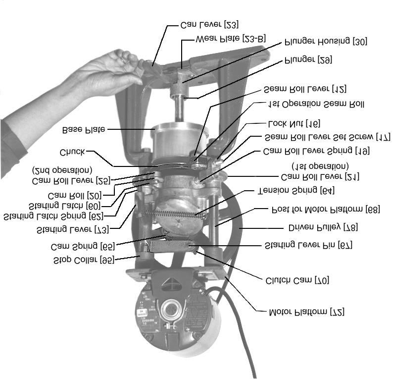
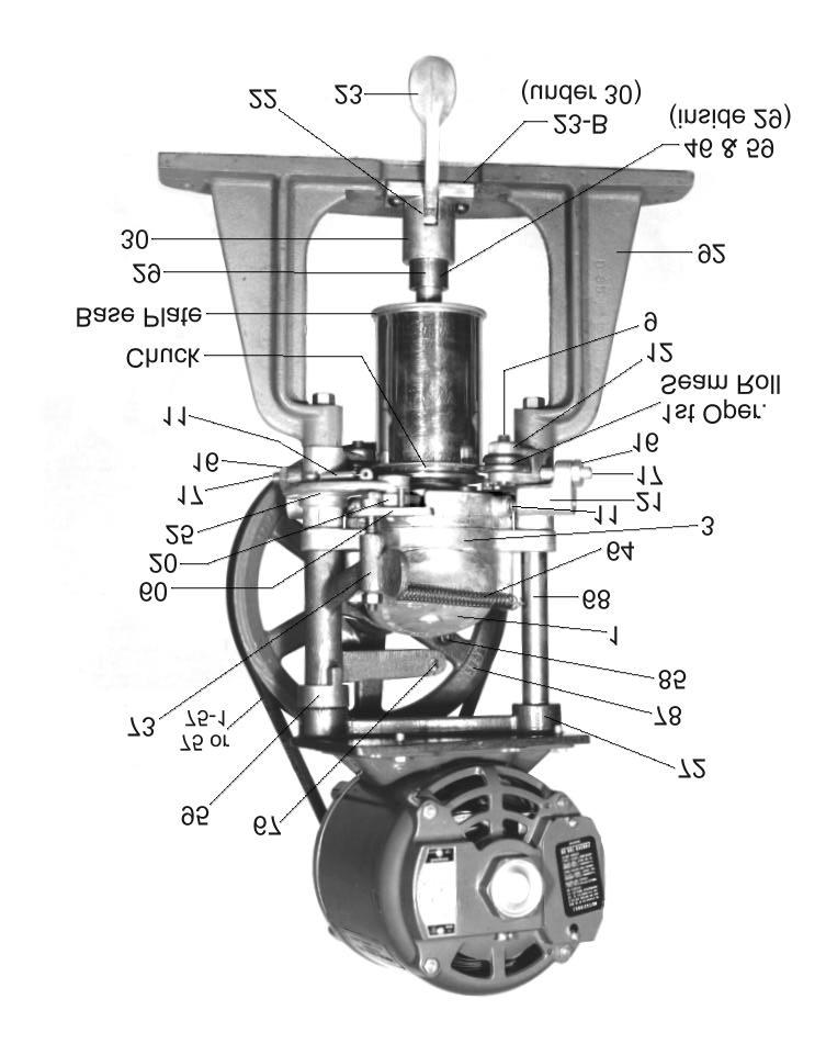
1 OPERATOR'S MANUAL Model 23 or 24 Belt Drive Electric Seamer Model (shown) If you are not experienced with your seamer, please read and understand this manual before operating the machine. If you have a question discuss it with your supervisor or contact Dixie Canner Company.
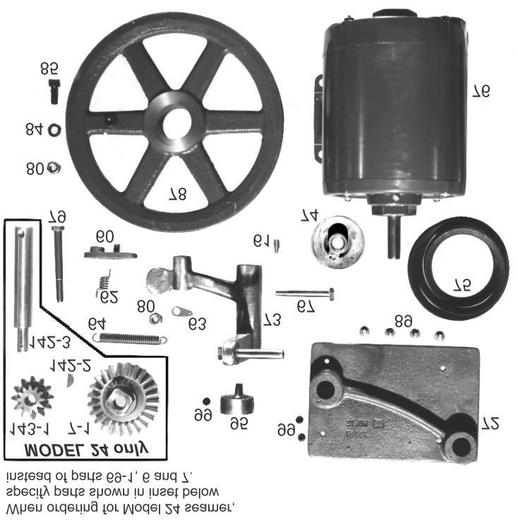
2 INTRODUCTION Dixie Model 23 and Model 24 Seamer are adaptable for closing round, rigid containers with lightweight metal ends from 200 to 404 diameters (2" to 4¼" diameters) and up to five inches tall. At time of fabrication, the Model 24 may be fabricated with extension posts to accommodate containers taller than five inches. Model 23 Seamers are equipped with die cast bevel gears and are recommended for closing cans with a filled weight of less than two pounds. The maximum can height for a Model 23 Seamer is five inches. Model 24 Seamers are equipped with one steel bevel gear and one bronze bevel gear, and a drive shaft with a keyway. Model 24 Seamers may close cans with filled weights of more than two pounds and which may exceed five inches in height. Following the model number of either seamer are digits to indicate the height of the extension posts used in the seamer (i.e., the tallest can height the seamer may accept). Machines built to handle cans taller than five inches will also have the same digits on the frame extension posts. Instructions for operating, adjusting, changing, timing, etc., outlined in this manual are referenced to the seamer mounted on a table or counter top. Drawings and sectional views are shown within this manual to illustrate specific details. The can revolves only during the seaming cycle. Both seaming rolls automatically operate by a seaming cam to assure a perfect seam when properly adjusted. Seam rolls are full floating and interlock with the chuck in such a manner as to remain in perfect alignment and eliminate damage to the rolls or chuck through faulty adjustment. The seamer was equipped with seaming rolls, chuck and base plate to close a specific can size. Unless otherwise specified, the motor was shipped with a 115 volt AC motor, 1/3 HP, 1725 RPM. A special chuck wrench for installing or removing chucks and a set of gauge wire for setting initial seam adjustments were included with your seamer. Refer to Parts List pages for optional equipment or accessories that may have been ordered with this seamer which may include change parts for different can sizes, tools and spare parts. INSTALLATION Unpack the seamer base and attach seamer securely to table or bench. 1. Install the motor and V-belt drive. 2. Install the belt guard. When electrical current is supplied to the seamer, the large driven pulley turns counterclockwise (with the operator facing the seamer), and cam roll levers are in neutral position. When the start lever is moved quickly to the left and then released, the clutch cam is engaged with the driving pin which causes the chuck to turn the correct number of times to seam a can. The chuck will stop automatically with both cam roll levers in neutral position. OPERATION 1. Raise can lever [23] to horizontal position which lowers the base plate. 2. Place top on the can to be closed and set can on the base plate. Press can lever [23] downward thus raising the can and clamping the top (lid) tightly against the chuck. 3. Move the starting lever [73] to the left until the starting latch [60] engages against the tit of the cam housing [8]. The can will be sealed automatically then stop turning. 4. Raise the can lever and remove the can. CHANGING FROM ONE SIZE CAN TO ANOTHER Change parts consisting of a chuck, a base plate and a height spacer may be required for each different can diameter, top or style. Also, a different set of seaming rolls may be required for each. Your can manufacturer or supplier may recommend the seam roll profiles for your cans. Dixie stocks or may be able to furnish the seam roll profile needed. Make sure you have the correct change parts available when changing your machine from one can size to another, then proceed as follows: 1. Turn driven pulley [78] until seam rolls assume their neutral position. 2. Loosen lock nuts [16] and loosen set screws [17] until seam roll levers [12] are back as far as they will go. 3. Remove tension spring [64) and housing cover [1] to expose the upper end of the chuck shaft [14-1]. 1
3 4. Change chucks. CAUTION: To prevent damage to the chuck shaft and/or internal gears, use an open end wrench to hold the chuck shaft while loosening or tightening the chuck. To remove the chuck, hold the chuck shaft [14-1] with a wrench on the top of the shaft, located under the gear housing cover. Then place the two pins of the chuck wrench [44], provided with your seamer, into two of the four holes located on the bottom of the chuck. (The pins of the chuck wrench will fit into either diagonal or adjacent holes depending on the diameter of the chuck.) To loosen, turn the chuck to the left. Finish removing the chuck by hand. To install a new chuck, hold the chuck shaft with a wrench, as described above, while using your hand to thread the chuck onto the lower end of the chuck shaft. Turn to the right to thread the chuck onto the chuck shaft. Use the chuck wrench, as described above, to tighten snugly. Make certain that the new chuck is properly tightened into position against the shoulder of the chuck shaft. 5. Replace gear housing cover [1]. 6. Install the proper base plate for the can to be closed. 7. Replace the housing cover and tension spring. 8. Adjust the base plate pressure and seam rolls as outlined on the following page. CAUTION: Seam roll screws [9] have left hand threads and must be turned clockwise to loosen. ADJUSTING THE STOP COLLAR The purpose of the stop collar [95] is to regulate the movement of the starting lever [73]. Adjust as follows. 1. Loosen set screw in the stop collar. 2. Carefully move the starting lever to the left until the notch of the starting latch lodges on the cam housing protrusion marked oil. While holding the starting lever in this position, turn the stop collar to the right until it fits against the slot in the starting lever. 3. Tighten set screw to hold the stop collar securely in position, making certain that the starting lever operates freely. NEUTRAL POSITION The machine is in a neutral position when both cam rolls [20] are in their innermost position and both seaming rolls are in their outermost position. TIMING THE SEAMER Timing of the seamer is proper when, at the end of the seaming cycle, both cam roll levers [21 and 25] are in neutral position. The driven pulley [78] turns freely. The seamer may be timed as follows. 1. Make sure power to seam is off. 2. Remove the drive belt [75]. If you are unable to roll the drive belt off of the driven pulley [78], loosen or remove the motor to allow more slack in the drive belt so it may be removed. 2
4 3. Expose the bevel gears by removing the housing cover cam stud [66] is at twelve o clock position, the loose leg [1], clip for tension spring [63] and tension spring [64]. of the spring should point at one or two o clock. Replace Inspect bevel gears [6 and 7] for damaged cogs or teeth any of these parts as needed. After placing a new cam and replace as necessary. spring [65] on the cam stud [66], slightly squeeze the coil of the cam spring to be sure it is snugly positioned. Then, if necessary, used needle-nosed pliers to slightly bend the 4. Pull starting lever [73] to the left until it engages the starting latch [60]. leg of the cam spring [65] near the coil to insure that it 5. Apply slight pressure (toward the right) to the starting points toward the one or two o clock position before lever and slowly turn the driven pulley [78] 10 turns placing the leg under the spring stop pin [151]. counterclockwise until the starting latch [60] releases. The gap between the starting lever pin and the clutch cam should be no more than 1/4 to 3/4 inch. TO TIGHTEN V-BELT 6. If the seamer is not in time by the 10th turn, remove the cotter pin [100] from the drive shaft [69-1] and apply backward pressure against the driven pulley [78] to force the drive shaft to slip out of the small bevel gear. Remove the drive shaft bevel gear [6] while being careful not to move the larger bevel gear [7]. 7. Slowly turn the driven pulley [78] counter-clockwise as outlined in Step 5 until the gap between the pin for the starting lever [73] and the toe of the clutch cam [70] is between 1/4 and 1 inch. Carefully align and re-insert small bevel gear [6] onto the drive shaft [69-1]. Do not allow the larger bevel gear to move during this procedure or your seamer will become out of time. (Model 24's must have the woodruff key [142-2] properly positioned in the keyway of the drive shaft [142-3]). Replace cotter key [100]. 8. Check correct timing by turning the driven pulley [78] counterclockwise 20 revolutions while holding the starting lever [73] as described in Step 5. The seamer should stop in neutral position. If necessary repeat steps 6 and 7, moving the drive shaft bevel gear ONE cog at a time until the seamer is correctly timed. 9. Replace the cotter key and bend it snugly around the drive shaft. Replace gear housing cover [1] and tension spring [64]. Be sure the clip for starting latch [63] is placed properly to provide adequate tension on the spring to allow the starting latch [64] to engage when the starting lever [73] is pulled to start the seaming cycle. NOTES: If you continue to have noise or locking problems after following the preceding instructions, check the starting lever [73], the pin for the starting lever [67], and the screw for the starting latch [79] for damage or excessive wear. Improper alignment of these parts may cause the pin for the starting lever [67] to strike the clutch cam [70] instead of passing by it. Additionally, check the cam stud [66], the cam spring [65] and the spring stop pin [151] for damage or excessive wear. Check the cam spring [65] by removing the long leg of the spring from under the spring stop pin [151]. When the The V-belt should be sufficiently tight to prevent slippage during the seaming operation. Adjust as follows. 1. Loosen mounting screws in motor base and insert thin washers to raise the motor and tighten the belt. Tighten screws securely. 2. Loosen set screws in the motor platform and adjust upward or downward on the posts for the motor platform. Tighten set screws. CAM HOUSING INSERT The insert [8-B] in the cam housing [8] is held in position by peening the casting. The insert is then machined to the correct dimension to allow the shoulder on the chuck shaft to protrude slightly. If it becomes necessary to replace the insert, be certain that it is properly seated, trimmed or machined so that it does not retard the turning of the chuck or the chuck shaft. SEAMING ROLL ADJUSTMENTS There are twenty (20) revolutions per seaming cycle, ten (10) for each seaming roll. The function of the first operation seam roll is to curl the cover hook and body hook into proper position. The function of the second operation seam roll is to complete the sealing of the can. FIRST OPERATION 1. Make certain that electrical current to motor is OFF and that both cam roll levers are in neutral position (driven pulley turns freely without engaging the chuck). 2. Engage the automatic clutch by moving the starting lever [73] to the left and turning the driven pulley [78] counterclockwise until the driving pin [85] comes into contact with the heel of the clutch cam [70], at approximately the one o clock position. 3. From this one o clock position, turn the driven pulley exactly nine (9) revolutions counterclockwise. Now the first operation seam roll is at its innermost position in relation to the chuck. 3
![4. Loosen lock nut [16] and adjust set screw [17] until the first operation seam roll is snugly in position with the chuck.](/docs-images/95/126361738/images/5-0.jpg "While holding the first operation (larger) gauge wire [40] in position between the chuck lip and the ground profile of the first operation seam roll, tighten the lock nut.")
5 4. Loosen lock nut [16] and adjust set screw [17] until the first operation seam roll is snugly in position with the chuck. While holding the first operation (larger) gauge wire [40] in position between the chuck lip and the ground profile of the first operation seam roll, tighten the lock nut. DO NOT PLACE WIRE IN GROOVE OF SEAMING CHUCK. The larger diameter gauge wire [40] is the approximate THICKNESS of the first operation seam. There should be sufficient friction to turn the seam roll as the gauge wire is moved back and forth. Too much pressure may cause damage to the machine. Insufficient pressure may result in producing a short cover hook. Final adjustments may be made after a can is closed and the double seam inspected. 5. Tighten lock nut [16]. Use a 3/6" allen wrench to keep screw [17] from turning when tightening the lock nut. SECOND OPERATION 1. After adjusting first operation roll, turn the driven pulley exactly nine (9) more revolutions counterclockwise. This is equivalent to eighteen turns from the original one o clock position and brings the second operation seam roll to its innermost position in relation to the chuck. 2. Loosen lock nut [16]. Place the second operation (smaller) gauge wire [41] in the groove of the second operation seam roll and adjust the screw [17] until the gauge wire fits snugly between the roll and the roughened or knurled edge of the chuck. Move gauge wire back and forth to allow sufficient friction to turn seam roll. DO NOT PLACE WIRE IN GROOVE OF SEAMING CHUCK. The small diameter gauge wire [41] represents the approximate THICKNESS of the second roll seam. Final adjustments may be made after a can is closed and the double seam inspected. 3. Tighten lock nut [16]. Use a 3/16" allen wrench to keep screw [17] from turning when tightening the lock nut. Move the gauge wire back and forth to ascertain that sufficient friction turns the seam roll. Too much pressure may damage the double seam at the can body side seam and insufficient pressure will not produce a proper seal. 4. Turn driven pulley two additional revolutions to place seamer in neutral position. 5. Close a can, tear down and inspect the double seam. Make final adjustments of the seaming rolls and base plate pressure to produce essential body hook, cover hook, overlap and tightness recommended by the container manufacturer or for a hermetically sealed can. NOTE: If you are unable to obtain the essential measurements recommended or a hermetically seamed container, you may need seam rolls with different profiles. NOTE: When adjusting seam rolls, make sure you start from neutral position. Count carefully number of turns of driven pulley. Be sure seam roll is in its innermost position when inserting gauge wire. Also be sure to place the gauge wire in the groove of the seam roll, NOT in the groove of the chuck. If your seamer shows a tendency to work overly hard, or lock, check adjustments of the seam rolls. CAUTION: To avoid damage to your seamer, make sure that the seam roll is no closer to the chuck than to allow the small gauge wire to pass. BASE PLATE PRESSURE ADJUSTMENTS Proper base plate pressure is required to produce essential body hook and prevent slipping of can during the seaming cycle. Each base plate has an adjusting screw [57] and set screw [56] in its stem for making minute base plate adjustments as follows: 1. Lift base plate out of plunger [29] and inspect the two metal discs [46]. Replace metal discs if there is any sign of undue wear or breakage. To replace the metal discs, first remove the plunger housing [30] and disassemble. Through the hole in the bottom of the plunger [29], insert a nail or punch and knock out the metal discs [46] and retainer spring [59]. Replace with new discs and reassemble, making certain that the retainer spring and metal discs are properly seated and that the entire assembly is adequately lubricated (oiled and greased). 4
6 SECTIONAL VIEW OF BASE PLATE ASSEMBLY 2. Insert screwdriver in the hole in the top of the base plate and loosen set screw [56] by turning counter clockwise. 3. Turn adjusting screw [57] in the proper direction to lengthen or shorten effective height of the base plate, as may be required for proper tension (pressure). If you find it necessary to use pliers to turn the adjusting screw, be very careful not to damage threads. 4. Tighten set screw snugly. It may be necessary to hold the end of the adjusting screw firmly while tightening the set screw. 5. Make certain that the base plate assembly is properly lubricated (greased) and replace the base plate in the plunger. NOTES: To achieve proper base plate pressure, the can must be raised the correct distance so that the cover (lid) is clamped against the seaming chuck. If the can lever [23] does not lock the can into place correctly, make sure the base plate you are using was fabricated for the can you are closing. Inspect the can lever [23] and wear plate [23-B] for damage or excessive wear. The wear plate [23-B] may o be turned 180 to provide a new edge for locking the can lever into place. Replace parts as needed. (Always keep the can lever [23] well greased at its contact point with the wear plate [23-B].) TESTING THE DOUBLE SEAM Before seaming a large number of cans or when changing from one size to another, ordinary precaution must be used to determine that the seamer is in proper adjustment and a satisfactory seam has been achieved. Can seam inspection should be performed routinely to ensure the seamer is in proper adjustment. Seam a test can and inspect the double seam for droops, vees, tightness or other possible defects. If your can manufacturer has provided you with seam specifications, take measurements of the seam to be sure your seam is within recommended tolerances. Dixie offers a Can Seam Test Kit that will enable you to measure different aspects of the double seam. If you are testing only for an airtight or hermetic seal, various rule-of-thumb methods may be used such as immersion in water to check for air bubbles which may indicate leakage. Please check with your supervisor to determine the seam test method that is proper for your purposes. Refer to instructions for adjusting seam rolls and changing from one size can to another to readjust your seamer as necessary to obtain a correct double seam. MAINTENANCE OF SEAMER With ordinary care, your Dixie seamer should give you excellent trouble free service if the following simple rules are observed. 1. Keep the seamer in proper adjustment at all times. 2. Replace worn parts as needed. 3. Clean thoroughly after each daily use. 4. Apply a few drops of lightweight oil to all exposed moving parts and in all holes plainly marked OIL. At the start of each season and periodically thereafter, remove housing cover [1] and apply grease to gears [6] and [7]. Use fitting on gear housing cover to grease chuck shaft. Use fitting on gear housing [3] to grease drive shaft [69-1]. CHANGE PARTS AND REPAIR PARTS When ordering parts, always furnish both the part number and the name of the part. When ordering change parts for cans, always send six (6) loose tops and can bodies of the size can(s) to be closed. These samples are require to fabricate the change parts. Please also provide seam specifications and seam roll profiles, if available. REPAIR PARTS AND REBUILDING SERVICE A complete stock of parts is maintained by Dixie Canner Company. Parts may be ordered as needed to replace worn or damaged parts. Your Dixie Double Seamer may be returned to Athens, Georgia for complete rebuilding at a nominal service charge, 5
7 plus the cost of parts needed. When returning the machine rolls should turn freely but without up and down for the rebuilding service, please observe the following: movement or wobble. If undue wear is evident, 1. Return the complete machine and include several cans replace with new screws and/or seam rolls. and tops of the exact size and type closed. Properly crate the machine and cans for safe delivery and return D. Seaming rolls do not return to neutral position. shipment, and prepay the shipping cost. 1. Seaming roll levers [12] binding. 2. Write a letter authorizing the rebuilding service and 2. Seaming roll lever spring [11] weak or broken. mention any problem with the machine. Also mention 3. Machine not properly timed. particular instructions concerning return shipment, E. Machine seems to "labor" or freeze tight. urgency, and other pertinent instructions. 1. Needs oil and/or grease. 2. Too much base plate pressure. HELPFUL HINTS TROUBLESHOOTING 3. Seaming rolls too tight. 4. Misalignment of moving parts. Until the operator is familiar with the mechanics of the DOUBLE SEAM DEFECTS seamer and learns to recognize irregularities in the essential & COMMON CAUSES requirements of the double seam, the outline below is intended to help notice obvious defects and list some causes A. Cut over. Unusually sharp edge at top inside edge of seam. that may serve as a guide in correcting minor troubles. MECHANICAL DEFECTS & COMMON CAUSES A. Can slips during seaming operation. 1. Damage or lack of grease in the base plate, lift shaft, or height spacer. 2. Insufficient base plate pressure. Worn or broken metal discs in base plate seat. Remove base plate from plunger and check metal discs [46]. Replace discs if broken or excessively worn. 3. Worn or wrong size chuck. Make sure that the lid fits properly against the chuck; the lid should fit snugly but should not bind. Dixie chucks are custom fabricated to fit the specific end which you submitted when the chuck was ordered. If you have changed lid styles, you may need a new chuck. 4. Seaming rolls binding on screws. B. Machine operates with undue noise or "locks." 1. Machine not properly timed. 2. Broken drive shaft bevel gear. Remove gear housing cover [1] and check drive shaft bevel gear [6]; if broken, replace as follows: a. With machine in neutral position, remove cotter key [100], then push drive shaft [69-1] backwards and to remove old gear. Insert new drive shaft bevel gear [6]. CAUTION: To avoid changing the timing, do not allow larger bevel gear [7] to move while changing the smaller bevel gear. b. Reposition drive shaft [69-1]; insert cotter key [100], then replace housing cover. 3. Damaged or worn starting lever [73] or pin for starting lever [67]. 4. Damaged or worn cam spring [65], cam stud [66] and/or spring stop pin [151]. C. Unusually loose seaming rolls. 1. Seaming rolls or seam roll screws [9] worn. Seam 1. 1st or 2nd operation seam roll set too tight. 2. Worn seam rolls or worn chuck. B. Cut or fractured seam. 1. Seam rolls set too tight. C. Droop or lap in double seam at or near can body side seam. 1. Too much base pressure. 2. 1st operation seam roll set too loose. 3. Worn 1st operation seam roll. D. Excessive countersink depth. 1. Too much base pressure. 2. 1st operation seam roll set too loose. 3. Chuck not properly seated in can top. 4. Chuck groove worn. E. False seam. Body hook and cover hook do not overlap. 1. Can top not properly seated on can. 2. Damaged can flange or can top curl. F. Long body hook. 1. Too much base pressure. G. Long cover hook. 1. 1st operation seam roll set too tight. H. Short body hook. 1. Insufficient base pressure. 2. 1st operation seam roll set too tight. 3. 2nd operation seam roll set too loose. I. Short cover hook. 1. Too much base pressure. 2. 1st operation seam roll set too loose. 3. Worn 1st operation seam roll. 4. Excessive countersink depth. J. Cover hook or body hook not uniform. 1. Base plate or plunger worn. 2. Chuck or seam rolls out of alignment. K. Droops, vees, wrinkles. 1. Excessive base pressure. 2. 1st operation seam roll too loose or worn. 3. 2nd operation seam roll too tight. 4. Defects in can body or top. 5. Incorrect seam roll profiles. 6
8 7
9 8
10 9
11 10
12 11
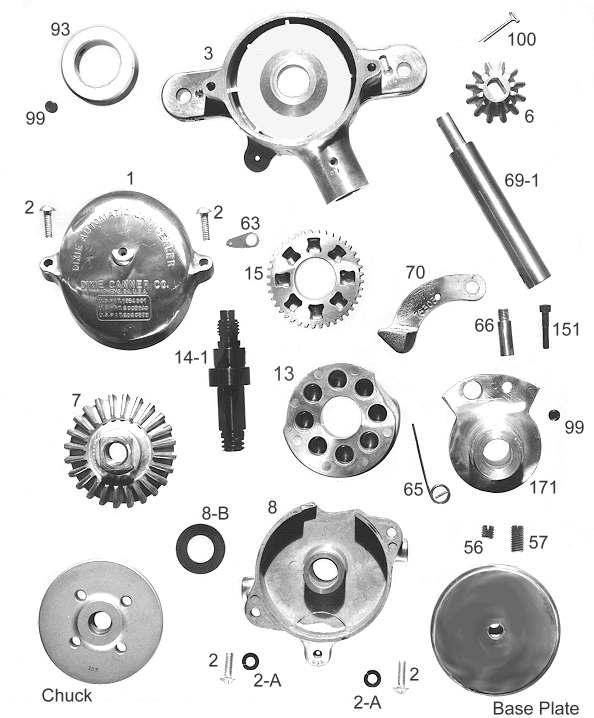
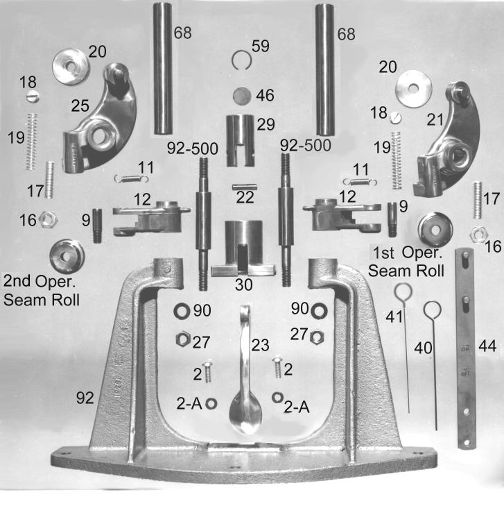
13 DIXIE MODEL 23 AND 24 ELECTRIC - PARTS PART NO. DESCRIPTION 1 Housing Cover 2 Screw 2-A Washer 3 Gear Housing 6 Model 23 Bevel Gear, Die Cast 7 Model 23 Bevel Gear, Die Cast 7-1 Model 24 Bevel Gear, Bronze 8 Cam Housing with 8-B Insert 8-B Insert for Cam Housing 9 Seam Roll Screw for Models 23/24 11 Seam Roll Lever Spring 12 Seam Roll Lever 13 Seaming Cam 14-1 Chuck Shaft 15 Spur Gear 16 Lock Nut, s/s 17 Seam Roll Lever Screw, Hex Head Swivel 18 Cam Roll Lever Set Screw 19 Cam Roll Lever Spring 20 Cam Roll 21 1st Operation Cam Roll Lever 22 Pin for Can Raising Lever 23 Can Lever 23-B Wear Plate 25 2nd Operation Cam Roll Lever 27 Nut 29 Plunger 30 Plunger Housing 40 1st Operation Gauge Wire (Specify container type) 41 2nd Operation Gauge Wire (Specify container type) 44 Chuck Wrench 46 Metal Disc for Base Plate 56 Base Plate Set Screw 57 Base Plate Adjusting Screw 59 Retainer Spring for Metal Disc 60 Starting Latch with Pin #61 62 Spring for Starting Latch 63 Clip, Tension Spring 64 Starting Lever Tension Spring
14 DIXIE MODEL 23 AND 24 ELECTRIC - PARTS PART NO. DESCRIPTION 65 Cam Spring 66 Cam Stud 67 Pin for Starting Lever No Post for Motor Platform 69-1 Model 23 Electric Drive Shaft 70 Clutch Cam 72 Motor Platform 73 Starting Lever with Pin No Driving Pulley, 1-1/2" x 1/2" 75-1 V-Belt, 1/2" x 34" /60/1 Motor 76-B Special Motor 110/ Driven Pulley with Pin 79 Cap Screw 80 Nut 84 Lock Washer 85 Driving Pin 89 Cap Screw0 90 Washer 92 Frame Casting 92- Frame Extension Post 93 Collar for Hub Shaft 94 Motor Cord/Switch 95 Stop Collar for Starting Lever 99 Set Screw 100 Cotter Key 102 Shipping Box 106 Model 23/24 Belt Guard 136 Screw Woodruff Key for Model Model 24 Drive Shaft Model 24 Bevel Gear, Steel 151 Spring Stop Pin 171 Clutch Sleeve 174 Grease Fitting for Housing & Pulley 175 Grease Fitting for Chuck Shaft
15 DIXIE MODEL 23 AND 24 ELECTRIC - PARTS PART NO. DESCRIPTION CHANGE PARTS Seam Rolls Seam Roll Bushing Chucks 108 to 404 diameter Add for Special Base Plates 108 to 404 diameter0 For Caulking Add for Modified Base Plate Height Spacer SPK/23 Model 23 Spare Parts Kit 2 9 Seam Roll Screw 3 11 Seam Roll Lever Spring 2 46 Metal Disc for Base Plate Seat 1 59 Retainer Spring for Metal Disc 1 62 Spring for Starting Latch 2 64 Starting Lever Tension Spring 1 65 Cam Spring 1 66 Cam Stud 2 67 Pin with Crown Nut & Washer 2 70 Clutch Cam Cotter Key Spring Stop Pin SPK/24 Model 24 Spare Parts Kit 2 9 Seam Roll Screw 3 11 Seam Roll Lever Spring 2 46 Metal Disc for Base Plate Seat 1 59 Retainer Spring for Metal Disc 1 62 Spring for Starting Latch 2 64 Starting Lever Tension Spring 1 65 Cam Spring 1 66 Cam Stud 2 67 Pin with Crown Nut & Washer 2 70 Clutch Cam Cotter Key Woodruff Key for Model Spring Stop Pin
Model 23H Hand Crank Seamer
 OPERATOR'S MANUAL Model 23H Hand Crank Seamer If you are not experienced with your seamer, please read and understand this manual before operating the machine. If you have a question discuss it with your
DIRECT DRIVE DIXIE DOUBLE SEAMER Model 25D
 OPERATOR'S MANUAL DIRECT DRIVE DIXIE DOUBLE SEAMER Model 25D LUBRICATE DAILY: A. Gears inside gear housing at chuck shaft (1) Oil B. Seam rolls and cam rolls (4) - Oil C. Seam roll levers through gear
OPERATOR'S MANUAL DIRECT DRIVE DIXIE DOUBLE SEAMER Model 10D
 OPERATOR'S MANUAL DIRECT DRIVE DIXIE DOUBLE SEAMER Model 10D OIL DAILY: A. Gears inside gear housing through oil groove in gear housing at cut surface of chuck shaft. (Oil through #517 gear housing cover
OPERATOR'S MANUAL DIRECT DRIVE DIXIE DOUBLE SEAMER. Model 25D
 OPERATOR'S MANUAL DIRECT DRIVE DIXIE DOUBLE SEAMER Model 25D OPERATOR'S MANUAL DIRECT DRIVE DIXIE DOUBLE SEAMER MODEL 25D INTRODUCTION DESCRIPTION Dixie Model 25D series of double seamers are adaptable
IMPORTANT: RECEIVING INSTRUCTIONS:
 Instruction Sheet Sidewinder Mechanical Bender IMPORTANT: RECEIVING INSTRUCTIONS: Visually inspect all components for shipping damage. If any shipping damage is found, notify carrier at once.shipping damage
LIQUIP DRYBREAK COUPLER. API800 Series MAINTENANCE INSTRUCTIONS
 LIQUIP DRYBREAK COUPLER API800 Series MAINTENANCE INSTRUCTIONS API LOADING COUPLER TO API RP1004 June 2015 Issue: F M:\Product-Info\API8xx\6-Service-Maintenance\API800 MAINTENANCE INSTRUCTIONS 40183.doc
Assembling a Can Sealer FNH-00022
 Assembling a Can Sealer FNH-00022 Technical revision in January 2009 by Kristy Long Extension Foods Specialist Cooperative Extension Service University of Alaska Fairbanks Photos by Jeff Fay Extension
OWNER'S MANUAL. Copyright 1999 ATS - All Rights Reserved
 OWNER'S MANUAL AL Issue 2 - August 19, 1999 Copyright 1999 ATS - All Rights Reserved OWNER'S MANUAL TABLE OF CONTENTS PAGE 1... WARRANTY PAGE 2... ASSEMBLY INSTRUCTIONS PAGE 4... MOUNTING THE RACQUET PAGE
OWNER'S MANUAL. Copyright 2003 GAMMA - All Rights Reserved
 OWNER'S MANUAL AL Issue 1 - December 2003 Copyright 2003 GAMMA - All Rights Reserved OWNER'S MANUAL TABLE OF CONTENTS PAGE 1... WARRANTY PAGE 2... ASSEMBLY INSTRUCTIONS PAGE 4... MOUNTING THE RACQUET PAGE
CHAPTER 5 REWIND STARTERS
 GENERAL INFORMATION CHAPTER 5 REWIND S Rewind starters used on vertical shaft Tecumseh engines are top mount horizontal pull style or side mount vertical pull style. Horizontal shaft engines use side mounted
6146XX-X OPEN STYLE HOSE REELS
 OPERATOR S MANUAL INCLUDING: OPERATION, INSTALLATION & MAINTENANCE 6146XX-XXX OPEN STYLE HOSE REELS LOW, MEDIUM & HIGH PRESSURE (FOR AIR, WATER & PETROLEUM PRODUCTS) 6146XX-X RELEASED: 2-5-90 REVISED:
MAGNETIC INDOOR CYCLING BIKE
 MAGNETIC INDOOR CYCLING BIKE SF-B1805 USER MANUAL IMPORTANT! Please retain owner s manual for maintenance and adjustment instructions. Your satisfaction is very important to us, PLEASE DO NOT RETURN UNTIL
7130 Lancer Rear Drive Magnetic Commercial Indoor Cycling Bike
 7130 Lancer Rear Drive Magnetic Commercial Indoor Cycling Bike Owner s Manual Made in Taiwan INDEX IMPORTANT SAFETY INFORMATION... 1 EXPLODED DRAWING... 2 PARTS LIST... 3 ASSEMBLY INSTRUCTION... 4-9 USER
1.0 - OPENING AND CLOSING THE DOOR
 The purpose of this manual is to provide the user with instructions on how to safely open and close, how to conduct routine maintenance, and how to install the PEI TWINLOCK Closure on a pressure vessel.
LIQUIP DRYBREAK COUPLER. LYNX Series MAINTENANCE INSTRUCTIONS
 LIQUIP DRYBREAK COUPLER LYNX Series MAINTENANCE INSTRUCTIONS API LOADING COUPLER TO API RP1004 February 2016 Issue: DRAFT A Issue: DRAFT - A 02/01/16 Page 1 CONTENTS LYNX Series Datasheet... 3 LYNX Series
OPERATIONS/PARTS MANUAL FOR PATTERSON'S WWP40M-12 and all WIDE DRUM variations of this HAND OPERATED WINCH.
 W. W. Patterson Company 3 Riversea Road Pittsburgh, PA 15233 Phone: 800-322-2018 FAX: 412-322-2785 OPERATIONS/PARTS MANUAL FOR PATTERSON'S WWP40M-12 and all WIDE DRUM variations of this HAND OPERATED WINCH.
Auto-Rewind Hose Reels INSTRUCTION MANUAL FOR OXY-LPG MODEL
 Auto-Rewind Hose Reels INSTRUCTION MANUAL FOR OXY-LPG MODEL Introduction Thank you for purchasing a Retracta Auto Rewind Hose Reel. The Retracta range of hose reels are a breakthrough in industrial quality
X-6FC STRINGING MACHINE OWNER'S MANUAL. Issue 1 - May Copyright 2004 GAMMA Sports - All Rights Reserved
 X-6FC STRINGING MACHINE OWNER'S MANUAL Issue 1 - May 2004 Copyright 2004 GAMMA Sports - All Rights Reserved OWNER'S MANUAL GAMMA X-6FC TABLE OF CONTENTS PAGE 1... WARRANTY PAGE 2... FEATURES PAGE 3...
OPERATIONS/PARTS MANUAL FOR PATTERSON'S WWP75H-10 HYDRAULIC WINCH.
 W. W. Patterson Company 3 Riversea Road Pittsburgh, PA 15233 Phone: 800-322-2018 FAX: 412-322-2785 OPERATIONS/PARTS MANUAL FOR PATTERSON'S WWP75H-10 HYDRAULIC WINCH. Please fill in the following blanks
600 / 600FC OWNER'S MANUAL
 PROGRESSION 600 / 600FC OWNER'S MANUAL Issue 2 / Version E - Dec. 10, 1997 Copyright 1997 GAMMA Sports - All Rights Reserved PROGRESSION 600 / 600FC OWNER'S MANUAL TABLE OF CONTENTS PAGE 1... WARRANTY
MUELLER GAS. No-Blo Operations Using D-5. Drilling Machine. Reliable Connections. General Information 2
 operating Instructions manual MUELLER GAS TAble of contents PAGE No-Blo Operations Using D-5 General Information 2 Installing No-Blo Service Tees, Service Stop Tees and Curb Stop Tees 3-8 Reconditioning
602 STRINGING MACHINE OWNER'S MANUAL
 PROGRESSION 602 STRINGING MACHINE OWNER'S MANUAL AL Issue 1- April 2000 Copyright 2000 GAMMA Sports - All Rights Reserved PROGRESSION 602 STRINGING MACHINE TABLE OF CONTENTS PAGE 1... WARRANTY PAGE 2...
Final Assembly Instructions Bikes with Quill Stems
 Final Assembly Instructions Bikes with Quill Stems Thank you for buying your new bicycle from L.L.Bean. Read these instructions carefully before beginning the final assembly. Prior to shipping, our expert
OPERATIONS/PARTS MANUAL FOR PATTERSON'S WWP50-H-14 HYDRAULIC WINCH.
 W. W. Patterson Company 3 Riversea Road Pittsburgh, PA 15233 Phone: 800-322-2018 FAX: 412-322-2785 OPERATIONS/PARTS MANUAL FOR PATTERSON'S WWP50-H-14 HYDRAULIC WINCH. Please fill in the following blanks
200 STRINGING MACHINE
 200 STRINGING MACHINE OWNER S MANUAL Issue 1 - July 2010 Provided by www.gssalliance.com 200 OWNER S MANUAL TABLE OF CONTENTS WARRANTY...PAGE 2 FEATURES...PAGE 3 ASSEMBLY INSTRUCTIONS...PAGE 4 MOUNTING
X-6 STRINGING MACHINE OWNER'S MANUAL. Issue 1 - May Copyright 2004 GAMMA Sports - All Rights Reserved
 X-6 STRINGING MACHINE OWNER'S MANUAL Issue 1 - May 2004 Copyright 2004 GAMMA Sports - All Rights Reserved OWNER'S MANUAL GAMMA X-6 TABLE OF CONTENTS PAGE 1... WARRANTY PAGE 2... FEATURES PAGE 3...ASSEMBLY
Final Assembly Instructions Bikes with Threaded Headsets
 Final Assembly Instructions Bikes with Threaded Headsets Thank you for buying your new bicycle from L.L.Bean. Read these instructions carefully before beginning the final assembly. Prior to shipping, our
OPERATING and MAINTENANCE INSTRUCTIONS MAXIS 6K Puller (M6K-M)
") OPERATING and MAINTENANCE INSTRUCTIONS MAXIS 6K Puller (M6K-M) READ AND UNDERSTAND ALL OF THE INSTRUCTIONS AND SAFETY INFORMATION IN THIS MANUAL BEFORE OPERATING OR 04/17 (M6K-M) SERVICING THIS TOOL TABLE
OPERATING and MAINTENANCE INSTRUCTIONS MAXIS 6K Puller (M6K-M) READ AND UNDERSTAND ALL OF THE INSTRUCTIONS AND SAFETY INFORMATION IN THIS MANUAL BEFORE OPERATING OR 04/17 (M6K-M) SERVICING THIS TOOL TABLE
Thumb Shifter Plus Thumb Shifter
 (English) DM-SL0004-01 Dealer's Manual Thumb Shifter Plus Thumb Shifter Thumb Shifter Plus SL-FT55 SL-TX50 SL-TX30 Thumb Shifter SL-TZ20 IMPORTANT NOTICE This dealer's manual is intended primarily for
SANTANA STOWAWAY TANDEM WITH AIRLINER SAFECASE AND FTS FOAM TRAY SYSTEM ASSEMBLY AND DISASSEMBLY
 SANTANA STOWAWAY TANDEM WITH AIRLINER SAFECASE AND FTS FOAM TRAY SYSTEM ASSEMBLY AND DISASSEMBLY Congratulations! You are now the proud owner of the world s most travel-ready, performance tandem. The following
BELT DRIVE INDOOR CYCLING BIKE SF-B1712 USER MANUAL
 BELT DRIVE INDOOR CYCLING BIKE SF-B1712 USER MANUAL IMPORTANT! Please retain owner s manual for maintenance and adjustment instructions. Your satisfaction is very important to us, PLEASE DO NOT RETURN
Shifting Lever. Dealer's Manual. RAPIDFIRE Plus SL-M2000 SL-M3010 SL-M4010. Thumb Shifter SL-TZ500. ROAD MTB Trekking. City Touring/ Comfort Bike
 (English) DM-MDSL001-01 Dealer's Manual ROAD MTB Trekking City Touring/ Comfort Bike URBAN SPORT E-BIKE Shifting Lever RAPIDFIRE Plus SL-M2000 SL-M3010 SL-M4010 Thumb Shifter SL-TZ500 CONTENTS IMPORTANT
BELT DRIVE INDOOR CYCLING BIKE SF-B1712
 BELT DRIVE INDOOR CYCLING BIKE SF-B1712 USER MANUAL IMPORTANT! Read all instructions carefully before using this product. Retain owner s manual for future reference. For customer service, please contact:
Final Assembly Instructions Bikes with 16 Wheel Size
 Final Assembly Instructions Bikes with 16 Wheel Size Thank you for buying your new bicycle from L.L.Bean. Read these instructions carefully before beginning the final assembly. Prior to shipping, our expert
Rear Drive System SERVICE INSTRUCTION. Specifications SI-R670B
 - SERVICE INSTRUCTION SI-R670B t Rear Drive System Before use, read these instructions carefully, and follow them for correct use. In order to realize the best performance, we recommend that the following
MANUAL SEALLESS STEEL STRAPPING TOOL MODEL A
 OPERATION MANUAL / SPARE PARTS LIST MANUAL SEALLESS STEEL STRAPPING TOOL MODEL A337.0001 13.1912.01 13191201.en/MAS/ 10.02 INDEX PAGE 1 SAFETY INSTRUCTIONS 2 2 WARRANTY CONDITIONS AND LIABILITY 4 3 APPROPRIATE
KTM OM-2 SPLIT BODY FLOATING BALL VALVES INSTALLATION AND MAINTENANCE INSTRUCTIONS
 Before installation these instructions must be fully read and understood SECTION 1 - STORAGE 1.1 Preparation and preservation for storage All valves should be properly packed in order to protect the parts
BUTTERFLY VALVES Series 800
 BUTTERFLY VALVES Series 800 WARNING Before proceeding read ALL instructions and become familiar with the equipment and associated drawings. Follow ALL applicable safety regulations and codes for pressurized
MAINTENANCE PROCEDURE FOR X 650
 MAINTENANCE PROCEDURE FOR X 650 X 650 25. juli 2005-1/6 MAINTENANCE PROCEDURE FOR X 650 2 ND STAGE WARNING: This maintenance procedure is only for appointed Scubapro technicians that completed a course
MUELLER. Mega-Lite Drilling Machine. Reliable Connections. table of contents PAGE. Equipment 2. Operating Instructions 3-4. Parts Information 5
 operating Instructions manual MUELLER Mega-Lite Drilling Machine table of contents PAGE Equipment 2 Operating Instructions 3-4 Parts Information 5 Travel Charts 6-11! WARNING: 1. Read and follow instructions
DelVal Flow Controls Private limited
 DelVal Flow Controls Private limited (A DIVISION OF DelTech CONTROLS LLC, USA) DelVal Series 50/5, 5A/5B Butterfly Valves INSTALLATION, OPERATION AND MAINTENANCE MANUAL ENGINEERING DATA SHEET E.D.S. NO
3/8" Dr. Air Butterfly Impact Wrench
 8192106 3/8" Dr. Air Butterfly Impact Wrench Owner s Manual Read and understand all instructions before use. Retain this manual for future reference. Specifications Construction: Polished aluminum and
Paintball Marker. User s Manual. 530 South Springbrook Road Newberg, OR 97132
 Paintball Marker User s Manual 530 South Springbrook Road Newberg, OR 97132 Component Concepts, Inc., 530 South Springbrook Road, Newberg, OR 97132 Phone: (503) 554-8095 Fax: (503) 554-9370 www.phantomonline.com
USER MANUAL
 C Cimarron Sports 1-888-816-6517 www.cimarronsports.com Combo Pitching Machine USER MANUAL TABLE OF CONTENTS Thank you for purchasing the Cimarron Combo Pitching Machine. The Cimarron Combo Pitching Machine
Assembly Drawing: W-311B-A01, or as applicable Parts List: W-311B-A01-1, or as applicable Special Tools: , , &
 REDQ Regulators Model 411B Barstock Design Powreactor Dome Regulator OPERATION AND MAINTENANCE Contents Scope..............................1 Installation..........................1 General Description....................1
Fontaine Fifth Wheel Ultra LT Rebuild Procedures
 Fontaine Fifth Wheel Ultra LT Rebuild Procedures Disassembly Assembly Adjustments 800-874-9780 2010 LT-147 January 2010 Dissassembly Cover plate removed for clarity. Refer to exploded view of assembly
Santa Fe Cycles Assembly Guide Introduction
 Santa Fe Cycles Assembly Guide Introduction Congratulations on your purchase of your new Santa Fe bicycle. You have purchased a bicycle that has many features and qualities. Please take a few minutes and
OPERATING and MAINTENANCE INSTRUCTIONS MAXIS 3K Puller (M3K-M)
") OPERATING and MAINTENANCE INSTRUCTIONS MAXIS 3K Puller (M3K-M) 04/17 (M3K-M) READ AND UNDERSTAND ALL OF THE INSTRUCTIONS AND SAFETY INFORMATION IN THIS MANUAL BEFORE OPERATING OR SERVICING THIS TOOL TABLE
OPERATING and MAINTENANCE INSTRUCTIONS MAXIS 3K Puller (M3K-M) 04/17 (M3K-M) READ AND UNDERSTAND ALL OF THE INSTRUCTIONS AND SAFETY INFORMATION IN THIS MANUAL BEFORE OPERATING OR SERVICING THIS TOOL TABLE
RS(H)10,15 USER MANUAL. Read the complete manual before installing and using the regulator.
10,15 USER MANUAL. Read the complete manual before installing and using the regulator.") RS(H)10,15 USER MANUAL Read the complete manual before installing and using the regulator. WARNING INCORRECT OR IMPROPER USE OF THIS PRODUCT CAN CAUSE SERIOUS PERSONAL INJURY AND PROPERTY DAMAGE. Due to
RS(H)10,15 USER MANUAL Read the complete manual before installing and using the regulator. WARNING INCORRECT OR IMPROPER USE OF THIS PRODUCT CAN CAUSE SERIOUS PERSONAL INJURY AND PROPERTY DAMAGE. Due to
accidents which arise due to non-observance of these instructions and the safety information herein. SPECIFICATIONS
 18 GAUGE 1-1/4 INCH BRAD NAILER Model: 7611 CALIFORNIA PROPOSITION 65 WARNING: You can create dust when you cut, sand, drill or grind materials such as wood, paint, metal, concrete, cement, or other masonry.
Cantilever Brake. Dealer's Manual. ROAD MTB Trekking. City Touring/ Comfort Bike
 (English) DM-RCBR001-00 Dealer's Manual ROAD MTB Trekking City Touring/ Comfort Bike URBAN SPORT E-BIKE Cantilever Brake BR-CX70 BR-CX50 BL-4700 BL-4600 BL-R780 BL-R3000 ST-7900 ST-6700 ST-5700 ST-4600
Pressure Dump Valve Service Kit for Series 3000 Units
 Instruction Sheet Pressure Dump Valve Service Kit for Series 000 Units. Overview The Nordson pressure dump valve is used to relieve hydraulic pressure instantly in Series 00, 400, 500, and 700 applicator
READ ALL INSTRUCTIONS AND WARNINGS BEFORE USING THIS PRODUCT.
 Drywall Stills DS1830 Max Weight Capacity 225 Lb READ ALL INSTRUCTIONS AND WARNINGS BEFORE USING THIS PRODUCT. This manual provides important information on proper operation & maintenance. Every effort
Service and Repair Manual
 II stage R2 Ice/ Special, II stage R 1 Pro DOWNSTREAM 2 nd STAGE REGULATOR Service and Repair Manual Introduction Safety Precautions...4 General Procedures, Maintenance Schedules...5 Initial Inspection
OPERATIONS/PARTS MANUAL FOR PATTERSON'S MODEL # WWP40M-LPS-6 LOW-PROFILE BARGE CONNECTOR WINCH
 W. W. Patterson Company 3 Riversea Road Pittsburgh, PA 15233 Phone: 800-322-2018 FAX: 412-322-2785 OPERATIONS/PARTS MANUAL FOR PATTERSON'S MODEL # WWP40M-LPS-6 LOW-PROFILE BARGE CONNECTOR WINCH Please
MASTER TRUING STAND TS-3. Optional Dial indicator set with brackets Dial indicator bracket set only
 MASTER TRUING STAND TS-3 3 2 1 3 8 9 4 10 7 6 5 12 13 Optional 1555-1 Dial indicator set with brackets 1556-1 Dial indicator bracket set only 49 11 16 14 15 48 32 31 37 38 20 19 17 18 34 39 21 36 22 33
310 SERIES TILT-TO-LOAD ROTATOR. The Specialist In Drum Handling Equipment
 OPERATOR S MANUAL FOR MORSE TILT-TO-LOAD DRUM ROTATOR SAFETY INFORMATION: While Morse Manufacturing Co. drum handling equipment is engineered for safety and efficiency, a high degree of responsibility
DM-MARD (English) Dealer's Manual. ROAD MTB Trekking. City Touring/ Comfort Bike REAR DERAILLEUR XTR RD-M9100 RD-M9120
 Dealer's Manual. ROAD MTB Trekking. City Touring/ Comfort Bike REAR DERAILLEUR XTR RD-M9100 RD-M9120") (English) DM-MARD001-00 Dealer's Manual ROAD MTB Trekking City Touring/ Comfort Bike URBAN SPORT E-BIKE REAR DERAILLEUR XTR RD-M9100 RD-M9120 CONTENTS CONTENTS...2 IMPORTANT NOTICE...3 TO ENSURE SAFETY...4
(English) DM-MARD001-00 Dealer's Manual ROAD MTB Trekking City Touring/ Comfort Bike URBAN SPORT E-BIKE REAR DERAILLEUR XTR RD-M9100 RD-M9120 CONTENTS CONTENTS...2 IMPORTANT NOTICE...3 TO ENSURE SAFETY...4
DM-RD (English) Dealer s Manual. ROAD Rear Derailleur RD-9000 RD-6800 RD-5800 RD-4700
 Dealer s Manual. ROAD Rear Derailleur RD-9000 RD-6800 RD-5800 RD-4700") (English) DM-RD0003-09 ROAD Rear Derailleur Dealer s Manual RD-9000 RD-6800 RD-5800 RD-4700 CONTENTS IMPORTANT NOTICE...3 TO ENSURE SAFETY...4 LIST OF TOOLS TO BE USED...6 INSTALLATION...8 Chain length...
(English) DM-RD0003-09 ROAD Rear Derailleur Dealer s Manual RD-9000 RD-6800 RD-5800 RD-4700 CONTENTS IMPORTANT NOTICE...3 TO ENSURE SAFETY...4 LIST OF TOOLS TO BE USED...6 INSTALLATION...8 Chain length...
TBV OPERATION AND MAINTENANCE MANUAL SERIES 2800: FLANGED BALL VALVE. For technical questions, please contact the following:
 TBV OPERATION AND MAINTENANCE MANUAL SERIES 2800: FLANGED BALL VALVE For technical questions, please contact the following: Engineering Department 1537 Grafton Road Millbury, MA 01527 Phone: (508) 887-9400
Installation, Operation and Maintenance Manual for Back Pressure Regulator
 Installation, Operation and Maintenance Manual for Back Pressure Regulator Model 8860 2009 Groth Corporation IOM-8860 Rev. B 12541 Ref. ID: 95565 Page 2 of 13 Table of Contents I. INTRODUCTION 3 II. DESIGN
STRINGING MACHINE OWNER'S MANUAL. Issue 5 - November 2012
 602 STRINGING MACHINE OWNER'S MANUAL Issue 5 - November 2012 2 602 MP602-12 OWNER S MANUAL TABLE OF CONTENTS WARRANTY... PAGE 3 FEATURES... PAGE 4 ASSEMBLY INSTRUCTIONS... PAGE 5 MOUNTING THE FRAME...
accidents which arise due to non-observance of these instructions and the safety information herein. SPECIFICATIONS
 18 GAUGE 2 INCH BRAD NAILER Model: 7555 CALIFORNIA PROPOSITION 65 WARNING: You can create dust when you cut, sand, drill or grind materials such as wood, paint, metal, concrete, cement, or other masonry.
X-6 STRINGING MACHINE
 X-6 STRINGING MACHINE MMAN-37 (MGX6-12) GAMMA SPORTS 200 Waterfront Drive Pittsburgh, Pennsylvania 15222 Phone: 800.333.0337 Fax: 412.323.0317 Visit our website at www.gammasports.com Copyright 2011 GAMMA
2,500/4,000 LB Easy Riser Vertical Cable Feighner Lift
 2,500/4,000 LB Easy Riser Vertical Cable Feighner Lift CAUTION - PUT SAFETY FIRST 1. Before attempting to install or operate this lift, study and fully understand the proper operating procedures and safety
Hydraulic Punch Drivers
 SERVICE MANUAL 7804SB / 7806SB Quick Draw 7704SB / 7706SB Quick Draw Flex Quick Draw Hydraulic Punch Drivers Serial Codes AHJ and YZ Read and understand all of the instructions and safety information in
Pressure Dump Valve Service Kit for Series 2300 Units
 Instruction Sheet Pressure Dump Valve Service Kit for Series 00 Units. Overview The Nordson pressure dump valve is used to relieve hydraulic pressure instantly in Series 00 applicator tanks when the unit
VL 2K LIFT D-L WINCH INSTRUCTIONS (Applies to P/Ns , , , , , )
") VL 2K LIFT D-L WINCH INSTRUCTIONS (Applies to P/Ns 3714022, 3714028, 3714034, 3714040, 3714043, 3714046) REIMANN & GEORGER CORPORATION MARINE PRODUCTS BUFFALO, NY P/N 6112103 04/09/18 1 SAFETY 1.1 INTRODUCTION
VL 2K LIFT D-L WINCH INSTRUCTIONS (Applies to P/Ns 3714022, 3714028, 3714034, 3714040, 3714043, 3714046) REIMANN & GEORGER CORPORATION MARINE PRODUCTS BUFFALO, NY P/N 6112103 04/09/18 1 SAFETY 1.1 INTRODUCTION
DBML-60/80 Squeeze Tool
 DBML-60/80 Squeeze Tool OPERATORS MANUAL Description The Mustang Model DBML-60/80 Hydraulic squeeze tool has been manufactured since 1995. A Mustang 3 3/4 bore doubleacting cylinder producing 41,000 lbs
Final Assembly Instructions Bikes with Threaded Headsets
 Final Assembly Instructions Bikes with Threaded Headsets Thank you for buying your new bicycle from L.L.Bean. Read these instructions carefully before beginning the final assembly. Prior to shipping, our
STYLE 3414/3416 & 3421/3423 Apollo Monitor with Foldaway Legs OPERATING & MAINTENANCE INSTRUCTIONS
 STYLE 3414/3416 & 3421/3423 Apollo Monitor with Foldaway Legs OPERATING & MAINTENANCE INSTRUCTIONS The Akron Style 3414/3416 & 3421/3423 Apollo Monitor is designed to provide efficient trouble-free operation
SIGNATURE DEF REELS Models: Bare Reel Reel Reel Reel
 SERVICE BULLETIN SB2023 Rev C 7/11 SIGNATURE DEF REELS Models: 2400-006 Bare Reel 2400-007 16 Reel 2400-008 20 Reel 2400-009 30 Reel Thoroughly read and understand this manual before installing, operating
Nexus. Dealer's Manual. ROAD MTB Trekking. City Touring/ Comfort Bike SG-3R40 SG-3R45 SG-3R75 SG-3R75-A SG-3R75-B SG-3D55 SG-3C41
 (English) DM-SG0005-01 Dealer's Manual ROAD MTB Trekking City Touring/ Comfort Bike URBAN SPORT E-BIKE Nexus SG-3R40 SG-3R45 SG-3R75 SG-3R75-A SG-3R75-B SG-3D55 SG-3C41 SL-3S35-E SL-3S41-E SL-3S42-E SM-BC03
DM-MBRD (English) Dealer's Manual. ROAD MTB Trekking. City Touring/ Comfort Bike. Rear Derailleur SLX RD-M7000 DEORE RD-M6000
 Dealer's Manual. ROAD MTB Trekking. City Touring/ Comfort Bike. Rear Derailleur SLX RD-M7000 DEORE RD-M6000") (English) DM-MBRD001-04 Dealer's Manual ROAD MTB Trekking City Touring/ Comfort Bike URBAN SPORT E-BIKE Rear Derailleur SLX RD-M7000 DEORE RD-M6000 CONTENTS IMPORTANT NOTICE... 3 TO ENSURE SAFETY... 4
(English) DM-MBRD001-04 Dealer's Manual ROAD MTB Trekking City Touring/ Comfort Bike URBAN SPORT E-BIKE Rear Derailleur SLX RD-M7000 DEORE RD-M6000 CONTENTS IMPORTANT NOTICE... 3 TO ENSURE SAFETY... 4
709 and 710 Stud Punches
 INSTRUCTION MANUAL 709 and 710 Stud Punches Read and understand all of the instructions and safety information in this manual before operating of servicing this tool. IMPORTANT SAFETY INFORMATION 709 and
Arbor Terminator Press Operation Manual For IDT Connectors Order No Engineering No: AM
 Arbor Terminator Press Operation Manual For IDT Connectors Order No. 11-20-0815 Engineering No: AM7223-140 Description Operation Maintenance Order No: TM-011200815 Release Date: 03-08-12 UNCONTROLLED COPY
M16 R / M1600 R USER S MANUAL WARNING: READ THE INSTRUCTIONS AND SAFETY PRECAUTIONS IN THIS MANUAL CAREFULLY BEFORE USING THIS FIREARM.
 ARMSCOR M16 R / M1600 R USER S MANUAL WARNING: READ THE INSTRUCTIONS AND SAFETY PRECAUTIONS IN THIS MANUAL CAREFULLY BEFORE USING THIS FIREARM. DISCHARGING FIREARMS IN POOLY VENTILATED AREAS, CLEANING
OPERATIONS/PARTS MANUAL FOR PATTERSON'S HAND OPERATED WINCH
 DOC # 5071-A W. W. Patterson Company 3 Riversea Road Pittsburgh, PA 15233 Phone: 800-322-2018 FAX: 412-322-2785 OPERATIONS/PARTS MANUAL FOR PATTERSON'S HAND OPERATED WINCH Please fill in the following
U.S. Patent No. 7,922,246. Patents Pending
 U.S. Patent No. 7,922,246 Patents Pending 2 Table of Contents Page General Information... 3 Warnings and Cautions... 4 Tools... 6 SmartDock Parts... 6 Initial Set-Up and Adjustment... 7 Select Valve Retaining
TECHNICAL INFORMATION
 TECHNICAL INFORMATION Model No. Description RP2300FC, RP2301FC Router CONCEPT AND MAIN APPLICATIONS Models RP2300FC and RP2301FC are upgraded sister tools of our current plunge-type electronic router Model
Installation Troubleshooting Maintenance Instructions Installation / Start-up
 Model ZW207 Installation Troubleshooting Maintenance Instructions Installation / Start-up NOTE: Flushing of all pipe lines is to be performed to remove all debris prior to installing valve. 1. For making
DM-FD (English) Dealer's Manual. Front derailleur FD-M9000 FD-M9020 FD-M9025 FD-M8000 FD-M8020 FD-M8025 FD-M612 FD-M617 FD-M618 FD-M672
 Dealer's Manual. Front derailleur FD-M9000 FD-M9020 FD-M9025 FD-M8000 FD-M8020 FD-M8025 FD-M612 FD-M617 FD-M618 FD-M672") (English) DM-FD0003-04 Front derailleur Dealer's Manual FD-M9000 FD-M9020 FD-M9025 FD-M8000 FD-M8020 FD-M8025 FD-M612 FD-M617 FD-M618 FD-M672 FD-M677 CONTENTS IMPORTANT NOTICE... 3 TO ENSURE SAFETY...
(English) DM-FD0003-04 Front derailleur Dealer's Manual FD-M9000 FD-M9020 FD-M9025 FD-M8000 FD-M8020 FD-M8025 FD-M612 FD-M617 FD-M618 FD-M672 FD-M677 CONTENTS IMPORTANT NOTICE... 3 TO ENSURE SAFETY...
A. TO PREPARE THE MACHINE FOR USE.
 INSTRUCTION MANUAL FOR THE ML120 STRINGING MACHINE. CONTENTS: A. TO PREPARE THE MACHINE FOR USE. 1. The assembly of frame with console and tooltray. 2. Fixing the lever of the tension unit. 3. Putting
OPERATORS MANUAL MODEL 365 BACK LAPPING MACHINE WARNING
 MODEL 365 BACK LAPPING MACHINE OPERATORS MANUAL WARNING You must thoroughly read and understand this manual before operating the equipment, paying particular attention to the Warning & Safety instructions.
CLASS CYCLE P8000 OWNER'S MANUAL JOHNSON HEALTH TECH. CO., LTD.
 CLASS CYCLE P8000 JOHNSON HEALTH TECH. CO., LTD. No.26, Ching Chuan Rd., Taya Hsiang, Taichung Hsien 428, Taiwan, R.O.C. TEL: +886-4-2566700 FAX: +886-4-2560087 E-mail: sales@johnsonfitness.com http://www.johnsonfitness.com
INSTALLATION & MAINTENANCE INSTRUCTION
 ARCHON Industries, Inc Liquid Level Gauges Models: BT-LLG ND-LLG INSTALLATION & MAINTENANCE INSTRUCTION Instruction No.: 1014.2 Revision Issued: 3/01/03 Approved: Engineering Manager Warning ONLY QUALIFIED
Shoreline Cantilever Lift 2500lb Capacity Models: (108" inside width) - Part # (120" inside width) - Part #
 - Part # (120 inside width) - Part #") Shoreline Cantilever Lift 2500lb Capacity Models: 25108 (108" inside width) - Part # 1017402 25120 (120" inside width) - Part # 1017403 1. 2. 3. 4. 5. CAUTION - PUT SAFETY FIRST Before attempting to install
Shoreline Cantilever Lift 2500lb Capacity Models: 25108 (108" inside width) - Part # 1017402 25120 (120" inside width) - Part # 1017403 1. 2. 3. 4. 5. CAUTION - PUT SAFETY FIRST Before attempting to install
TRAILMATE METEOR ASSEMBLY MANUAL
 TRAILMATE METEOR ASSEMBLY MANUAL (DISC BRAKE VERSION) The Trailmate Meteor recumbent has been designed for easy assembly. This means more time to enjoy the smooth ride with single speed, 3 speed coaster
PRS(TC)4,8 USER MANUAL. Read the complete manual before installing and using the regulator.
4,8 USER MANUAL. Read the complete manual before installing and using the regulator.") PRS(TC)4,8 USER MANUAL Read the complete manual before installing and using the regulator. WARNING INCORRECT OR IMPROPER USE OF THIS PRODUCT CAN CAUSE SERIOUS PERSONAL INJURY AND PROPERTY DAMAGE. Due to
PRS(TC)4,8 USER MANUAL Read the complete manual before installing and using the regulator. WARNING INCORRECT OR IMPROPER USE OF THIS PRODUCT CAN CAUSE SERIOUS PERSONAL INJURY AND PROPERTY DAMAGE. Due to
Instruction Manual LIMITED 1 YEAR WARRANTY. Hydraulic Punch Driver Read this material before using this product.
 Instruction Manual Hydraulic Punch Driver 902-483 LIMITED 1 YEAR WARRANTY We make every effort to assure that its products meet high quality and durability standards, and warrant to the original purchaser
MUELLER A A Non-Adjustable. Vertical Indicator Posts. Reliable Connections. General Information 2. Technical Data 3.
 Installation Instructions manual MUELLER table of contents PAGE A-20808 General Information 2 Technical Data 3 Dimensions 4 A-20809 Non-Adjustable Installation 5-6 Parts 7 Maintenance 8 Vertical Indicator
Have questions? Chat with us live at raleighusa.com or call us at , 8am 5pm PST
 1 2 Have questions? Chat with us live at raleighusa.com or call us at 1-800-251-8435, 8am 5pm PST The bicycle you have purchased is a complex piece of equipment that must be properly assembled and maintained
Front derailleur. Dealer's Manual FD-M9000 FD-M9020 FD-M9025 FD-M8000 FD-M8020 FD-M8025 FD-M612 FD-M617 FD-M618 FD-M672 FD-M677
 (English) DM-FD0003-05 Front derailleur Dealer's Manual FD-M9000 FD-M9020 FD-M9025 FD-M8000 FD-M8020 FD-M8025 FD-M612 FD-M617 FD-M618 FD-M672 FD-M677 CONTENTS IMPORTANT NOTICE... 4 TO ENSURE SAFETY...
DM-RBRD (English) Dealer's Manual. ROAD MTB Trekking. City Touring/ Comfort Bike. Rear Derailleur
 Dealer's Manual. ROAD MTB Trekking. City Touring/ Comfort Bike. Rear Derailleur") (English) DM-RBRD001-00 Dealer's Manual ROAD MTB Trekking City Touring/ Comfort Bike URBAN SPORT E-BIKE Rear Derailleur CLARIS RD-R2000 CONTENTS IMPORTANT NOTICE... 3 TO ENSURE SAFETY... 4 LIST OF TOOLS
(English) DM-RBRD001-00 Dealer's Manual ROAD MTB Trekking City Touring/ Comfort Bike URBAN SPORT E-BIKE Rear Derailleur CLARIS RD-R2000 CONTENTS IMPORTANT NOTICE... 3 TO ENSURE SAFETY... 4 LIST OF TOOLS
INDOOR CYCLING BIKE SF-B1110 USER MANUAL
 INDOOR CYCLING BIKE SF-B1110 USER MANUAL IMPORTANT! Read all instructions carefully before using this product. Retain owner s manual for future reference. For customer service, please contact: support@sunnyhealthfitness.com
Operating Procedures for GripTight 15.5 SDR & IPS Test Plugs
 EST Group DC2518 08/01 REV 3 12/12 Page 1 of 6 Operating Procedures for GripTight SDR & IPS Test Plugs WARNING For proper operation, GripTight plugs must be assembled as shown in Figure 1. Pressure testing
44in Side Discharge Mower for Wheel Horse XL 440H Lawn Tractors Model No Serial No and Up
 Form No. 5-8 in Side Discharge Mower for Wheel Horse XL 0H Lawn Tractors Model No. 790 Serial No. 5000000 and Up Operator s Manual Register your product at www.toro.com Original Instructions (EN) Contents
STAND AID 1600/ ECONOSTAND
 MAKERS OF STAND AID, POWER TOILET AID AND FREEDOM CHAIR STAND AID 600/ ECONOSTAND INSTRUCTIONS AND WARRANTY FOR STAND AID 600 STAND AID SERIAL # PO BOX 386 Sheldon, IA 50 (800) 83-8580 (7) 34-53 Fax: (7)
Constant Pressure Crude Oil Container Model CPCCP
 Installation, Operations, and Maintenance Manual Constant Pressure Crude Oil Container Model CPCCP The information in this manual has been carefully checked for accuracy and is intended to be used as a
TECHNICAL DATA ZTR Model 312
 DIXON INDUSTRIES. INC. A BLOUNT COMPANY AIRPORT INDUSTRIAL PARK PO BOX 1569 COFFEYVILLE KS 67337 0945 316 251 2000 FAX 316 251 4117 TECHNICAL DATA ZTR Model 312 IMPORTANT - READ OPERATOR'S MANUAL BEFORE