IALA Guideline No The Use of Aids to Navigation in the Design of Fairways. Edition 1. June 2011
|
|
|
- Linette Eaton
- 5 years ago
- Views:
Transcription

1 International Association of Marine Aids to Navigation and Lighthouse Authorities IALA Guideline No On The Use of Aids to Navigation in the Design of Fairways Edition 1 AISM Association Internationale de Signalisation Maritime IALA 10 rue Gaudine, Saint Germain en Laye, France Telephone: Fax: contact@iala-aism.org Internet:
2 Document Revisions Revisions to the IALA Document are to be noted in the table prior to the issue of a revised document. Date Page / Section Revised Requirement for Revision Page 2 of 42
3 Table of Contents DOCUMENT REVISIONS 2 TABLE OF CONTENTS 3 INDEX OF TABLES 4 INDEX OF FIGURES 4 1 INTRODUCTION Background Future Development 5 2 DEFINITIONS 6 3 USER REQUIREMENTS General Accuracy Reliability Special Requirements for different user groups 8 4 PERFORMANCE PARAMETERS OF ATON SYSTEMS Positioning Accuracy Radionavigation Systems Visual AtoN Drift Detection Redundancy Perception General Lights Daymarks Radar Automatic Identification System (AIS) 10 5 LAYOUT OF ATON FOR MARKING A FAIRWAY General AtoN Marking the Fairway Boundaries Other AtoN Marks in the Fairway Fixed visual AtoN Outside the Fairway Leading lines Sector lights 12 6 DESIGN METHODOLOGY/PROCEDURE A simple Procedure for the establishment of a Marked Fairway Channel Design and Maintenance Risk assessment Simulation 13 7 EXAMPLES OF MARKING OF FAIRWAYS 14 8 CONCLUSION 14 Page 3 of 42
4 Index of Tables Table 1 Definitions 6 Table 2 Synchronization of AtoN 36 Index of Figures Figure 1 Undetectable zone 16 Figure 2 Detectable manoeuvring lane for light buoys on the both sides of fairway 17 Figure 3 AtoN design on the Rio de la Plata 21 Figure 4 Mussalo Channel 23 Figure 5 Kotka inner harbours 24 Figure 6 Mussalo Harbour 25 Figure 7 Rauma Channel 28 Figure 8 Port of Rauma 29 Figure 9 Port of Le Havre 32 Figure 10 Example for different types of floating aids on the same fairway : Deep Water Buoy and hinged Beacon 35 Figure 11 Seekanal Rostock canal section 35 Figure 12 Example for synchronized AtoN : Inner part of Seekanal Rostock 36 Figure 13 Sea Chart of a part of the outer and inner channel Seekanal Rostock 37 Figure 14 Outer part of channel - Malmo 39 Figure 15 Inner part of channel - Malmo 40 Figure 16 Entrance to Malmo Harbour 41 Figure 17 Malmo Harbour 42 Page 4 of 42
5 1 INTRODUCTION The purpose of this Guideline is to give guidance for AtoN providers and competent authorities on the: use of AtoN in the design of fairways, including dredged channels and canals; and, review of existing AtoN for fairways including dredged channels and canals. The objective is to define a suitable AtoN mix that enables safe and efficient vessel passage in the most cost effective way for AtoN providers. This Guideline shall be used as a general overview. For more detailed AtoN planning, this document should be used in conjunction with other IALA documentation, especially the Maritime Buoyage System (MBS). 1.1 Background The art of navigation has evolved over many hundreds of years, as well as the design of vessels. For instance, vessels are bigger and faster; vessel equipage has become much more complex. In principle, navigation comprises: Planning a safe passage for a vessel, through the use of nautical charts and relevant publications; Monitoring or establishing a vessel s position or movement along a planned passage; and, Controlling a vessel, to ensure that it follows a planned passage. The navigation process is normally performed by the vessel s navigator. The navigator will normally combine the chart and navigational information whilst at the same time controlling the vessel. In some vessels, for some of the time, this process is fully automated, using electronic tools. This places great demand on the accuracy of the chart, the navigation system and the vessel s control systems. Complete automation cannot be fulfilled under all circumstances with today s technology. In general, it is considered that proper marking of waterways/fairways, dredged channels and canals by visual and radar aids remains important to mitigate risk. Until recently, mariners have used radionavigation systems (also referred as electronic AtoN) and short range visual systems, in two distinct ways. Short range visual AtoN were mostly used close to shore and in restricted waterways. Utilising radionavigation systems, vessels were able to navigate offshore safely using less accurate radionavigation systems. However, considering the availability, reliability and relatively low cost of high precision electronic position fixing systems (e.g. GPS/DGPS and electronic charting programs) available today, these two areas of navigation have become less distinct. This is especially true in those transitional areas where mariners shift from the low accuracy requirements of ocean navigation, to the high accuracy needs of coastal and inshore piloting. As electronic aids continue to improve, their use will increase in areas where short range aids were previously used. This evolutionary change must be considered when conducting waterway analysis and designing AtoN systems for fairways. 1.2 Future Development In future, e-navigation will have a considerable impact on the mix of AtoN for an existing or a planned fairway. e-navigation will help to improve the efficiency of fairway marking with AtoN by integrating the elements of information. Further on it will provide: improved safety, through promotion of standards in safe navigation; better protection of the marine environment; the potential for higher efficiency and reduced costs; and, a potential reduction in bureaucracy - e.g. standardised reporting requirements. Page 5 of 42
6 Elements of e-navigation, which are currently limited by availability of equipment and training of personnel, will be available in the future. Issues relating to the presentation of information still remain to be addressed. 2 DEFINITIONS Table 1 Definitions Term/Acronym Absolute Accuracy Absolute Position AtoN AtoN Provider Availability Canal Channel Conspicuity Continuity e-navigation ENC Fairway High Speed Craft (HSC) IHO IMO Integrity Luminous range Definition/Expansion The accuracy of a position estimate with respect to the geographic or geodetic co-ordinates of the Earth A position estimate with respect to the geographic or geodetic co-ordinates of the Earth Aid(s) to Navigation Any organisation, public or private, which is required to deploy AtoN as part of its duties The percentage of time that an aid, or system of aids, is performing a required function under stated conditions. Nonavailability can be caused by scheduled and/or unscheduled interruptions A narrow stretch of inland waterway created artificially to facilitate navigation Part of an (otherwise shallow) water having sufficient depth for vessels and designated or customarily used for vessels. The borders of the channel may be defined by natural or artificial banks or by AtoN The ability of an object to stand out from its surroundings The probability that, assuming a fault-free receiver, a user will be able to determine position with specified accuracy and is able to monitor the integrity of the determined position over the (short) time interval applicable for a particular operation within a limited part of the coverage area The harmonised collection, integration, exchange, presentation and analysis of maritime information on board and ashore by electronic means to enhance berth to berth navigation and related services for safety and security at sea and protection of the marine environment Electronic Navigation Chart A charted and marked waterway recommended by a competent authority Craft capable of maximum speed equal to or exceeding ms -1 where: = volume of displacement corresponding to the design waterline (m 3 ) This excludes WIG vessels International Hydrographic Organisation International Maritime Organisation The ability to provide users with warnings within a specified time when a system should not be used for navigation The distance from which, under defined conditions, the user can identify the light Page 6 of 42
7 Nominal range Radionavigation Radionavigation system Relative Accuracy Reliability SOLAS Useful range Waterways Wing in Ground (WIG) Luminous range in a homogeneous atmosphere in which the meteorological visibility is 10nm Radiodetermination used for the purpose of navigation, including obstruction warning Navigational system that uses radiofrequencies to determine a position The accuracy with which a user can determine position relative to that of another user of the same navigation system at the same time Ability of a device, or system, to satisfy the requirements of its intended use within defined limits, and for a stated period of time International convention for the Safety of Life at Sea The practical convenient range for a mariner to identify an AtoN Navigable waters Vessels, the hull of which is supported completely clear above the water surface in non-displacement mode, by aerodynamic forces generated by ground effect 3 USER REQUIREMENTS 3.1 General According to SOLAS, Chapter V, regulation 13, each of the Contracting Governments is required to provide, as it deems practical and necessary, AtoN, as the density of traffic and the level of risk requires. IMO member states commit themselves to take into account international recommendations and guidelines when establishing such aids. 3.2 Accuracy The required navigation accuracy for a vessel depends on the beam of the vessel, the draft of the vessel, the under keel clearance and the bathymetry and many other factors in the waterway. The position accuracy of the vessel should meet the required navigation accuracy. However, as there are many interacting variable properties of vessels and waterways, there will be a situation, where the navigation accuracy cannot be improved further by improving the position accuracy. The mariner needs to be able to determine exactly the distance from the vessel to certain points or lines; for instance, a critical hazard or the limitation of the fairway. This distance can then be calculated as the difference between two absolute positions. This distance is therefore dependent upon both the absolute position accuracy of the vessel and the relevant object. The distance can also be found directly, if there is a visual aid, or a radar target, or any other device indicating the relevant point or line. This is described by the relative accuracy..the principle of relative accuracy is often used for the layout of visual AtoN systems. The requirement for the position accuracy for radionavigation systems for general navigation is 10m for most of the different types of waterways 1. Position accuracies of radionavigation systems are considered as absolute. The position of the AtoN should be accurate and in accordance with IHO standards, in order that a vessel can establish its position sufficiently and follow a route in the fairway by visual or radionavigation means. 1 IMO Resolution A.915(22) Revised Maritime Policy and Requirements for a Future Global Navigation Satellite System (GNSS), adopted on 29 November 2001; and, A.953(23), World-Wide Radionavigation System, adopted on 5 December 2003 Page 7 of 42
8 The AtoN should be surveyed and positioned with at least the same accuracy as the nautical chart. This is determined in the IHO Standards for Hydrographic Surveys (S-44) 5th Edition February 2008 with accuracies of: 2 m for fixed aids (5 m when water depth more than 100 m); 10 m for floating aids (20 m when water depth more than 100 m). In many cases, these minimum requirements will not be accurate enough because of the specific layout of the system and its components. 3.3 Reliability In determining AtoN Reliability, such issues as Integrity, Availability, Continuity and mean time to repair (MTTR) need to be taken into account. The required level of AtoN Reliability is determined by the level of risks to the mariner, the vessel and the marine environment that are mitigated through the use of a particular AtoN. In those areas in which the level of risk has been determined to be high, the use of certain types of AtoN may prove to provide greater risk mitigation. The planner must consider availability objectives. AtoN providers should refer to IALA Recommendation O-130 on Categorisation and Availability Objectives for Short Range AtoN for additional information related to the categorization of individual AtoN, the calculation of availability targets, and recommended availability objectives. If continuity is used for defining the requirements for a specific system, it has to be calculated for the time that a vessel takes to pass through the fairway or area. 3.4 Special Requirements for different user groups The level of on-board navigational equipment can vary significantly on different types of vessels. SOLAS vessels are equipped with certified on-board navigational equipment. This is suitable to support long-range and/or low visibility navigation. These vessels are operated by professionally trained and certified personnel. For these vessels, visual AtoN are used as a back-up-system if radionavigation systems or on-board equipment fail. However, for vessels that are not SOLAS equipped 2, visual AtoN are more important. For High Speed Craft and other fast vessels in coastal areas, using visual AtoN for a safe passage, the speed of these vessels can be the defining factor for the AtoN system 3. The reaction time in these situations can be short, so the information provided by the AtoN needs to be quick and has to be unambiguous. 2 3 For instance, fishing vessels and leisure craft IALA Guideline No on the provision of AtoN for different classes of vessels, including high speed craft addresses the specific AtoN requirements of HSC. Page 8 of 42
9 4 PERFORMANCE PARAMETERS OF AtoN SYSTEMS 4.1 Positioning Accuracy Radionavigation Systems The position accuracy (95%) for a vessel using radionavigation systems augmented by differential systems 4 where appropriate can be assumed to be 10m. These systems provide absolute accuracy and absolute position information which should be used in conjunction with chart information. The accuracy of the chart has to be taken into account when using radionavigation systems Visual AtoN Generally, visual AtoN do not provide absolute accuracies of 10 m or less as presented to the user. However, and importantly, they provide a good relative accuracy. Thus, they are a good tool to determine the vessel s position relative to relevant objects, such as fairway boundaries and hazards. Due to differing mooring arrangements, the position accuracy of floating short range AtoN is sometimes difficult to define. Floating AtoN positions are subject to variation because of water depth, tides, current, mooring type and the capabilities of the servicing vessel in positioning the AtoN anchoring device Drift Detection There is not an internationally agreed method for calculating vessel positioning accuracy in a fairway that uses buoys and other AtoN. Research in the calculation and presentation of drift detection is currently taking place. For instance, a new drift detection method for vessels in a channel has been developed in Japan. Details of this method can be found at ANNEX B. 4.2 Redundancy Reliance upon a single AtoN may result in a higher availability requirement which may prove difficult for the provider to meet. Therefore, implementation of multiple aids should be considered to provide redundancy. Duplication of the navigational functions of a single AtoN may be appropriate to provide a degree of redundancy to avoid the excessive cost of emergency repairs. Moreover, temporary duplication may be provided when new or alternative types of aids are being introduced in order to allow a safe transition period. 4.3 Perception General When designing a fairway, the distance from which the AtoN can be detected, recognised and identified by the mariner, is a critical consideration. For visual perception, this is called the useful range. The useful range does not only depend upon the properties of the AtoN itself. The atmosphere and the human eye are the other determining factors. Therefore, useful range can be calculated using characteristics of the AtoN, atmosphere and the human eye (this is further determined by the experience of the observer). The conspicuity of an object is also relevant. An object is conspicuous if it appears outstanding in a complex visual scene. IALA guidance on this issue is included in certain IALA documents. To identify an AtoN, it is important that the visual information provided by the AtoN is verified. The mariner achieves this task by comparing the characteristics of the AtoN (e.g. shape, colour, daymark, lettering and light character.) This process can take time due to interference by intermittent influences such as wave movement and visibility. 4 IMO Resolutions A.915(22) and A.953(23) Page 9 of 42
10 4.3.2 Lights An AtoN light can be defined by its intensity, colour and divergence. When this light is measured in its practical application a further parameter is derived; the luminous range. The luminous range is the distance from which, under defined conditions, the user can identify the light. To identify the light, the mariner must be able to confirm its colour and character. The prevailing visibility conditions will vary for different geographical locations. Therefore, when selecting an AtoN light, these conditions should be taken into consideration. The nominal range will be promulgated in nautical charts and publications for mariners, lists of lights etc. The IALA E-200 series of Recommendations provides further information on the determination and measurement of marine signal lights Daymarks The distance at which a daymark can be identified depends on size, shape, colour, contrast to the background, environmental conditions, background and geographical range. The object can be normally identified when it subtends, at the eye, an angle of more than 3 (three minutes of arc). The contrast between the background and the AtoN depends on the: chromaticity of the paint of the AtoN; specific meteorological visibility in the area; colour and illumination of the background; conspicuity. Reflective sheets / retro-reflective material on the aid can be used at night to enhance the daymark in low visibility conditions Radar The perception of an AtoN by a vessel borne radar is determined by the: height of the vessel s radar; height of AtoN above actual sea level; Radar Cross Section of the AtoN (including any radar reflector); environmental conditions: - radar clutter due to sea state and weather; - movement of AtoN due to environmental conditions; active radar devices on the AtoN Automatic Identification System (AIS) Perception can be improved by means of AIS on AtoN, provided that the vessel s on-board equipment allows presentation of such information. Some of the benefits of AIS include: unambiguous indication of AtoN identity; day/night and all weather operation; greater range than most visual signals; enhanced perception, showing the position on the vessel s electronic chart; verification of the integrity of the aid, including Off-Position and operational status indication / malfunction alert to the mariner and AtoN provider; Page 10 of 42
11 additional broadcast of meteorological and hydrological data and safety related information in real time if suitable equipment is fitted to the AtoN. More Details on AIS and its implementation as an AtoN can be found in IALA Recommendation A- 126 on the use of AIS in Marine AtoN Services. 5 LAYOUT OF AtoN FOR MARKING A FAIRWAY 5.1 General When considering the design of a system of AtoN, the IALA Maritime Buoyage System (MBS) must be adhered to. However, for inland waterways, there may be different legislation, rules and marking systems established by national authorities; for example, SIGNI (Signs and Signals on Inland Waterways). The AtoN provider is responsible for ensuring that AtoN are identified and marked on nautical charts (ENC and paper charts). In narrow, winding or meandering passages, it may be difficult for mariners to correlate the vessel s position with chart information in a timely manner. In these circumstances, visual AtoN will be the primary means of navigation. 5.2 AtoN Marking the Fairway Boundaries The following general principles apply to the design of fairways: 1 A fairway shall be marked, in principle, by lateral marks. 2 There shall be AtoN at least at bends and junctions of the fairway. 3 Lit AtoN should be generally used for: a the beginning and end of the fairway; b changes of direction. 4 AtoN should be spaced evenly along the fairway, where practicable. 5 In general, the useful range of buoys at day and night should be greater than the distance between the buoys. The AtoN appearance on the vessel s radar screen should also be considered. 6 The distances between unlit AtoN are based on their size and daytime visibility. 7 In general, the AtoN on one or both sides of the fairway, should be positioned an equal distance from the central axis of the fairway. 8 If high navigational accuracy or a very clearly distinct fairway with continuous buoyage is required, ideally, the AtoN marking the fairway shall be established as pairs ( gates ); however, if this degree of accuracy is not required then a staggered arrangement of AtoN could be considered. Moreover, AtoN could be positioned to one side of the fairway only. 9 If a fixed AtoN separation distance is required, then the appropriate mark and size has to be established. If a certain type of mark/size of AtoN is preferred for a particular purpose, then the separation distance of the AtoN has to be determined. Usually, this will be an iterative process. More than one option should be examined and assessed against the level of risk, from the navigational, economical, technical and operational perspectives. 10 In general, a high density of fairway AtoN ensures an easy and more accurate level of navigation. However, there is a saturation point where adding AtoN does not help positioning any further. To find the ideal AtoN density, simulation and risk assessment will be necessary, or at least very useful in fairway design. 11 To make AtoN service provision more economical, providers should consider defining a restricted number of various types and classes of AtoN (by size and shape) with certain Page 11 of 42
12 identification distances and useful ranges of the lights. Thus, the most suitable AtoN can be chosen from this toolbox instead of designing a new one for each case. 5.3 Other AtoN Marks in the Fairway In addition to marking the boundaries of the fairway, short range AtoN and electronic AtoN may be used in the right mix to indicate: critical points; the centre of the fairway; change of direction; marking of isolated dangers; marking of different areas. The following marks can be used: Lateral, cardinal or safe water marks, which are physically deployed directly in the fairway, or on the point they indicate (or as close as possible to it). These can be floating (buoys) or fixed (beacons) aids. 5.4 Fixed visual AtoN Outside the Fairway Leading lines Leading lines (lit or unlit) generally provide high accuracy for the middle of the fairway. They can be established when there are straight stretches in the fairway Leading lines should be established if: the middle of a fairway needs to be indicated; other AtoN could be affected by ice, severe weather or tide; there is a channel inside the fairway, which has to be used by vessels with deep drafts; strong cross currents occur (for instance in harbour entrances); They can also be used to mark the boundaries of the fairway, provided this function is clearly shown in the relevant charts (see example in ANNEX G). The preliminary decision in designing a leading line is to define length and breadth of the section of fairway to be defined by the leading line. Generally, it is costly to build a leading line to serve a long channel, as the rear leading light must be of sufficient height to be clearly visible above the front structure. Leading marks must also be large enough to be visible from the far end of the section of fairway marked. Both these conditions result in increases to the required height of the rear structure marking a long channel. More Details can be found in IALA Guideline No for the design of leading lines and in the IALA NAVGUIDE Sector lights A sector light is an AtoN that displays different colours and/or rhythms over designated arcs. The colour of the light provides directional / positional information to the mariner. A sector, or a limit between two sectors, may indicate a fairway, a turning point, a junction with other fairways, a hazard or something else of importance for the navigator. When a fairway is covered by a sector light, colours indicating safe passage and danger areas are defined in the MBS. A sector light may indicate one or more of the following boundaries and aspects of a fairway; for example: position at which a change of course should be made; Page 12 of 42
13 location of shoals, banks, etc.; an area or position (e.g. an anchorage); and, the deepest part of a fairway. More details can be found in IALA Guideline No on Sector Lights. New developments in optimizing sector lights have recently taken place. For example, sector lights with oscillating boundaries are a powerful tool for lateral positioning in the fairway and considerations for their use can be found in the IALA NAVGUIDE. 6 DESIGN METHODOLOGY/PROCEDURE 6.1 A simple procedure for the establishment of a Marked Fairway The design of AtoN marking a fairway which is formed by straight lines and bends can be undertaken in three steps: 1 Establish a conspicuous AtoN, or pair of AtoN, at the beginning of the fairway. 2 Place AtoN at points where: a vessels have to alter their course; b the fairway boundary line or the middle line has a bend or curve; c critical shallows and rocks, or other hazards, form the boundary of the fairway; d fairways intersect. 3 Distribute buoys between these points with regard to the distance at which they can be detected and identified (refer to the section on perception of AtoN in this Guideline (section 4.3) and other relevant IALA documents). The distance, at which the marks should be detected and identified, may be different in relation to the length of the fairway for different cases as follows: a after the initial assumption of requirements made from section 4.3, the buoy separation distance should now be chosen as follows: b when the nearest buoy is being approached, the mariner should be able to see at least the next buoy along the fairway (the next two buoys in more accurate applications). 6.2 Channel Design and Maintenance Fairway planners in the relevant authorities should consider AtoN solutions to minimise the amount of dredging and surveying that is required in fairway construction and maintenance. Further details on these matters can be found in the PIANC Guide Approach Channels. 6.3 Risk assessment Advice on risk assessment and risk management can be found in IALA Guideline 1018 on risk management and IALA Recommendation O-134 on the IALA risk management tool for ports and restricted waterways. 6.4 Simulation Simulation can be used as a tool in the design and planning of fairways. Refer to IALA Recommendation O-138 on the Use of GIS and Simulation by AtoN Authorities and IALA Guideline 1058 on the use of simulation as a tool for waterway design and AtoN planning, for discussions on the use of simulation in fairway design and placement of AtoN. Page 13 of 42
14 7 EXAMPLES OF MARKING OF FAIRWAYS Some examples for the marking of fairways are given in ANNEX C to ANNEX G. 8 CONCLUSION When designing an AtoN system for an existing or a newly designed fairway, many considerations are necessary. The requirements can be defined in parameters such as accuracy, reliability and perception. The parameters vary depending on the type of fairway, the vessel traffic and on other factors. The design must include the considerations and requirements of international bodies such as the IMO, IHO, PIANC and IALA. e-navigation will integrate information on visual AtoN in the fairway with all the information available on the bridge of a vessel and thus contribute to the optimal use of the fairway. This is subject to further development, as currently many vessels are not equipped to use e-navigation applications. A systematic approach to the design of AtoN systems and fairways is an initial step towards AtoN integration in e-navigation. Continuous improvement of marking principles and AtoN positioning will optimise the fairway design, drive efficiencies and protect the marine environment. Page 14 of 42
15 ANNEX A RELEVANT IALA DOCUMENTATION 1 IALA AtoN GUIDE ( NAVGUIDE ) This document provides overall guidance, in particular chapters on AtoN and Risk Management. 2 IALA RECOMMENDATIONS 1 R-101 on Maritime Radar Beacons 2 E-105 on the need to follow national and international standards 3 E-110 for the Rhythmic Characters of Lights on AtoN 4 E-111 for Port Traffic Signals 5 E-112 for Leading Lights 6 O-113 for the Marking of fixed bridges over navigable waters 7 A-126 on the use of AIS in Marine AtoN Services 8 O-130 on categorization and availability objectives for short range AtoN 9 O-138 on the Use of GIS and Simulation by AtoN Authorities 10 E on Marine Signal Lights - Overview 11 E on Marine Signal Lights - Colours 12 E on Marine Signal Lights - Calculation, Definition and Notation of Luminous Range 13 E on Marine Signal Lights - Determination and Calculation of Effective Intensity 14 E on Marine Signal Lights - Estimation of the Performance of Optical Apparatus 3 IALA GUIDELINES on Racon range performance on Risk Management for the Design of Leading Lines on the Provision of AtoN for different classes of vessels, including high speed craft on Sector Lights on a Response Plan for the Marking of New Wrecks on the Provision of AtoN in Built-up Areas on the Use of Simulation as a Tool for Waterway Design and AtoN Planning on Light Application Illumination of Structures Other IALA Recommendations and Guidelines on VTS, AIS, Racons and DGPS should also be considered. Page 15 of 42
16 ANNEX B DRIFT DETECTION JAPANESE METHOD Extract from Japanese Method (contribution to Section 5 Fairway Layout and Channel Width to the Draft of the report of PIANC MARCOM Working Group 49 Horizontal and vertical dimensions of channels ). 1 CHANNEL CLASSIFICATION AND CHANNEL WIDTH ELEMENTS Channel width can generally be assumed to consist of the following fundamental elements: Width of basic manoeuvring lane: W W W S ) where W W m my W ( mi : width needed against wind and current forces : width needed against yawing motion W m S: width needed for drift detection. Additional width needed against bank effect forces: W bi ; m my Additional width needed against two-vessel interaction forces in passing condition: W c ; Additional width needed against two-vessel interaction forces in overtaking condition: W. ov It is noted that the total channel width may be obtained by summing up necessary elements mentioned above, not necessarily all, according to design purposes and detailed conditions for the subject channel. 2 EQUIPMENT AND SYSTEMS OF NAVIGATION AIDS A vessel sailing in a channel usually makes some amount of drift from its course line due to various causes together with external forces even if a vessel handler does believe that his vessel is running on track. Drift detection may be impossible when the drift amount is small, but a vessel handler can recognize a drift when a vessel makes some considerable amount of lateral deviation from its course line as shown in Figure 1. The drift amount which a vessel handler can detect depends on the type of equipment and systems of navigation aids together with the way in which they are utilized. It should be noted that the drift quantity to be detected plays an important role in the design of channel width. A narrower width may generally be adopted for a channel with a higher level of equipment and systems where the drift detection can be made more easily. Moreover, a vessel of larger size may be allowed to sail by installing a higher level of equipment and systems even in an existing channel which cannot be widened due to some topographical limitations. m Figure 1 Undetectable zone Page 16 of 42
17 As for the drift detection, in general, three types of equipment and systems of navigation aids are available as follows. Drift detection by observing light buoys ahead on both sides of channel with the naked eye. Drift detection by observing light buoys ahead on both sides of channel with RADAR. Drift detection by GPS or D-GPS. The channel width needed for the drift detection can be estimated with a detectable deviation from a course line with the use of the equipment and systems of navigation aids, as above, in each channel to be designed. 3 WIDTH NEEDED FOR DRIFT DETECTION As for the drift detection means by observing light buoys ahead on both sides of channel either with the naked eye or with RADAR, the channel width needed for the drift detection may be estimated on the basis of an angle made by two lines from a vessel to two buoys ahead on both sides shown in Figure 2, which is defined as: where Wbuoy 2 arctan (equation 1) 2LF W buoy : clearance between two buoys L F : distance along channel centre line form vessel to light buoys ahead. In equation 1, amounts of W buoy and L F are given in the following manner according to the subject channel of a newly designed channel or an existing channel. Buoy Buoy Wbuoy αmax LF θ Figure 2 Detectable manoeuvring lane for light buoys on the both sides of fairway 3.1 Newly designed channel In this case, W buoy is to be the channel width finally determined which is unknown in the beginning of channel width design. Therefore an iteration technique as described in is employed where assuming some amount of W iterations are made until computed value is to be finally identical buoy Wm(α) or Wm(R) Page 17 of 42
18 to the assumed one. Amounts of L F may be set empirically to be 7 LOA for a one-way channel and ( times of ( 3.5 7)L OA for a both-way channel. Moreover, L F may be set with a value of ) the distance between two successive buoys along a channel when buoy locations are given. 3.2 Existing channel W buoy is set with a clearance between two buoys on both sides of the channel, and L F is set with a distance between two successive buoys along a channel. However, when the distance between two successive buoys is thought to be somewhat long or more, L F may be set, in a similar way to the case of newly designed channel, to be 7 LOA for a one-way channel and ( 3.5 7)LOA for a bothway channel. 3.3 Drift Detection by Observing Light Buoys with Naked Eyes As shown in Figure 2, an angle made by two lines of a channel centre line and a line from a vessel to a midpoint of two buoys is denoted with. A concept of the maximum deviation is introduced which is defined that almost all vessel handlers are able to recognize a drift from its course line. Corresponding to this maximum deviation, the angle of is denoted with max as shown in Figure 2. Making use of the above concept of max, the channel width needed for the drift detection by observing light buoys with the naked eye can be calculated by: L Wm F tan max (equation 2) where max may practically be estimated with an empirical formula developed on the basis of statistical data by full scale experiments, which is given by: (equation 3) max 3.4 Drift Detection by Observing Light Buoys with RADAR The channel width needed for the drift detection by observing light buoys with RADAR can be calculated by: Wbuoy Wm R sin sin (equation 4) where : error of direction observation by RADAR. The following expressions are easily written from equation 4 for two cases of = 2deg. and 1 deg. respectively. Wbuoy Wm R ( : 2 deg.) (equation 5) sin Wbuoy Wm R ( : 1 deg.). (equation 6) sin 3.5 Drift detection by GPS In vessel manoeuvring operations with the utilization of GPS, a vessel handler may judge and recognize the vessel position by an image of GPS information displayed on an electric chart. Although image information on the electric chart is sufficiently accurate, the drift detection is made solely by perceiving a vessel movement on the display with the naked eye, and some amount of perception error should be taken into account. As for drift detection by means of GPS, an assumption is made for the above perception error to be a half of the vessel s breadth. In addition, the margin of error for GPS information error is assumed to be 30 meters for a standard GPS and none for a D-GPS. Therefore the channel width needed for drift detection by GPS and D- GPS can be calculated by the following equations, respectively: Page 18 of 42
19 GPS 0.5B 30 D GPS 0. B W m (unit: meter) (equation 7) W m 5 (unit: meter). (equation 8) In addition, it is noted that the channel width needed for drift detection by GPS should be designed with careful consideration of the risks involved in using GPS and GPS-related equipment. 4 REFERENCES [1] Ohtsu,K., Yoshimura,Y., Hirano,M., Tsugane,M.and Takahashi,H.: Design standard for fairway in next generation. Asia Navigation Conference 2006, No.26, [2] The Japan Port and Harbour Association: Technical Standards and Commentaries of Port and Harbour Facilities in Japan,2007.(in Japanese) Page 19 of 42
20 ANNEX C ATON DESIGN FOR THE RIO DE LA PLATA NAVIGATION CHANNEL The Rio de La Plata Navigation Channel is a partly straight and partly curved channel with buoys from a position of miles seawards of the harbour entrance of Buenos Aires. More data can be seen on the following chart. 1 SOME BASIC DATA Waterway in analysis Length: Width: Design Depth: Tidal range 63.8 M 100 m (one way channel) (there is a two way channel sector of 160 m) 34 feet 0.60 m 2 THE VESSEL TRAFFIC Total Traffic in the Area in 2006: vessels including Container vessels: 1,726 Bulk Carriers: 3,134 General cargo: 962 Oil Tanker: 1,386 Other: MAXIMUM SIZE OF VESSELS DIMENSIONS: Length BP Beam Design Draught Container vessel 261 m 40 m 41 feet Bulk carrier 260 m 42 m 42 feet Tanker 241 m 32.2 m 49 feet 4 AtoN The buoyage system is designed as paired buoys with the following parameters: Buoy separation distance average 3000 m (max m, min m) Buoy types Floating buoys and Spar Buoys Floating Buoy size above water level 4 m Spar Buoys size above water level: 8 m Additionally there are the following AtoN: DGPS coverage (on demand- private service) VTS and AIS control by Prefectura Naval Argentina (National Coast Guard) Mandatory Pilotage services Page 20 of 42
21 Figure 3 AtoN design on the Rio de la Plata Page 21 of 42
22 ANNEX D ATON DESIGN - FINLAND 1 MUSSALO FAIRWAY DATA Alignment and buoyage: The channel starts SW of Kotka Lighthouse and runs in a NE direction. E of the edge mark Kaakkoniemi it turns northwards towards the Deep Harbour of Kotka. Length 51 km/28 nm. 5 navigation lines, marked by boards and sector lights. Cardinal marks in the channel, lateral marks in the harbour. Lit. Dimensions: Design vessel: bulk carrier DWT, l = 300 m, b = 48 m, t = 15.3 m. Authorised draught 15.3 m, safe clearance depths (MW 90) 18.4 m, along the navigation line in the harbour 17.5 m. Minimum width 200 m. Anchorage areas etc.: Anchorage NE of Kaunissaari, close to crossroads. Safe clearance depth m. NAVIGABILITY Navigational conditions: The approach as far as the island Viikarinsaari consists of open sea, unsheltered against E S SW winds. Navigation may be hampered by strong winds and sea state. The channel is at its narrowest at the edge mark Elo 2, where it is only 510 m wide. Along the navigation line in the harbour the width is 200 m. RECOMMENDATIONS (channel) Speed: Vessels sailing at maximum draught should take the squat effect into account; design speed 16.5 knots (Sc 18.4) in the approach, 13 knots (Sc 17.5 m) in the harbour. TRAFFIC SERVICE Pilotage: Pilot order, tel Pilot boarding position \, \. Pilotage distance 25 nm. VTS: Kotka VTS, VHF Channel 67. Tugs: Provided by Alfons Håkans Ltd. Ordered by pilot, if required. PORT Quays: A Quay: length 609 m, safe clearance depth m; B Quay: length 500 m, safe clearance depth 11.7 m; C Quay: length 936 m, safe clearance depth 11.7 m; Liquid Bulk Terminal, berth N 1: length 69 m, safe clearance depth 15.0 m; Liquid Bulk Terminal, berth N 2: length 60 m, safe clearance depth 11.5 m. Cargo handling: A Quay four cranes (40 t), B Quay two cranes (40 t) and a mobile crane, C Quay four cranes (50 t). Harbour basin: Speed of vessel to be regulated to ensure that no harm or damage is caused. CONTACTS VTS: Kotka VTS tel fax Port: Port of Kotka tel fax of 42

23 Figure 4 Mussalo Channel 23 of 42


24 Figure 5 Kotka inner harbours 24 of 42
25 Figure 6 Mussalo Harbour 25 of 42
26 26 of 42
27 2 RAUMA 2.1 Rauma Channel CHANNEL DATA Alignment and buoyage: V of Rauma Lighthouse port. Four lines. Length approx. 26 km/14 nautical miles. Lateral marks. Lit. Dimensions: Design vessel: Ro-Ro vessel, L = 210 m, B = 30 m, T = 10.0 m. Maximum authorised draught 10.0 m, safe clearance depth (MW95) in the outer channel m, in the inner channel m. Minimum width 120 m, in the passage of Kovankivet 160 m; minimum bend radius 1000 m; design speed in dredged passages 12 knots. Anchorage and other special areas: In the outer channel, anchorage W of Rauma Lighthouse; beware of cable S of lighthouse. In the inner channel, anchorage and passage either in the widened area N of Rihtniemi or SW of Iso Järviluoto, approx. 1.5 km before arrival into port. NAVIGABILITY Navigational conditions: The outer channel to Rihtniemi is unsheltered and open to S-W-N winds. From Rihtniemi on, the channel continues as a narrow and densely marked channel, sheltered by isles, islands and mainland. Cross currents, which make the manoeuvring of large vessels more difficult, may occur when navigating the Urmluoto line in the passage of Kovankivet. Strong side winds also aggravate the side drift. Ice conditions: In winter ice fields tend to move in the channel, outside Hylkikarta. Ice movement may cause buoys to be pressed beneath the surface and their lighting devices may be damaged. OPERATIONAL RECOMMENDATIONS (channel and harbour) Wind: Max. speed of drifting wind gusts 18 m/s in daytime and 15 m/s at night. Limits lower for Ro-Ro vessels and vessels in ballast. Max. wind gusts 11 m/s for vessels in ballast, larger than the design vessel. Drifting wind means a wind which differs from the Urmluoto line by more than 30. Pilotage is discontinued when the wind speed exceeds 20 m/s. Visibility: The Urmluoto lines should be visible at night. Vessel-specific recommendations: Vessels larger than the design vessel and vessels with poor manoeuvrability are piloted only in daytime. New authorised channel draught practice applied in the channel as from July 15th, 2005 (NtM 17/2005, ). TRAFFIC SERVICE Pilotage: Pilot order, tel Pilot boarding position 61 07,5, 21 10,4. Pilotage distance 10 nautical miles. VTS: West Coast VTS, Channel 67 PORT Quays: Petäjäs: length 445 m, safe clearance depth m; Iso-Hakuni: 6 berths alongside/ro-ro berths, safe clearance depth m; Oil harbour: safe clearance depth m; Central harbour: length 665 m, Ro-Ro berth, safe clearance depth m; Laitsaari: length 246 m, safe clearance depth m; Inner harbour: 2 chemical piers, safe clearance depth m. Cargo handling: Petäjäs: cranes 40 t, 45 t and 16 t, pneumatic grain suction device; Iso-Hakuni: cranes and reach stackers; Oil harbour: piping, pumping power 1000 t; Central harbour: crane 6 t. Vehicle mounted cranes (50 and 100 t) used in all parts of the port. CONTACT INFORMATION VTS: West Coast VTS, Pori Tel Fax Port: Port of Rauma, Rauma Tel Fax Port Director Hannu Asumalahti 27 of 42


28 Guideline1078 The Use of Aids to Navigation in the Design of Fairways Figure 7 Rauma Channel 28 of 42


29 Figure 8 Port of Rauma 29 of 42
30 ANNEX E ATON DESIGN FOR LE HAVRE AND PORT 2000, FRANCE Le Havre (1st port in France) is a deep-water port with day and night access for the largest container carriers (10,000 TEUs and more). Located at the south end of the port, the facilities of the Le Havre oil port are made up of 8 specialised berths, including two for the reception of ,000dwt tankers. Recently, a new external port (Port 2000 terminals) able to welcome and rapidly handle the largest container carriers in the world in optimal logistic and nautical conditions has been created. The area is also one of the major places for pleasure and fishing craft in the region. 1 THE VESSEL TRAFFIC (PER YEAR) Total traffic flow: 80 million tons Container traffic flow: 2.5 million TEUs Oil: 40 millions tons Roll-on/roll-off services: vehicles Passengers: About vessel calls 2 MAIN WATERWAY IN ANALYSIS Length: Width: 12 nautical miles from the landfall buoy to the main entrance 450 metres (two-ways channel) 3 PORT 2000 WATERWAY Lenght: Width: Design Depth: Tidal range: 3 nautical milles 350 metres (two-ways channel for vessels up to 55 m beam) 15 meters + tide 8,00 metres 4 AtoN The buoyage system is designed as paired buoys with the following parameters: Buoy separation distance average 1400 m (max m in the entrance, minimum m at Port 2000); Buoy types: 18 Floating buoys and 3 fixed beacons (LH 17, 18 & 21) for the marking of the effective width of the fairway (EWF); Floating Buoy size above water level: 3,5 m with a luminous range of 3 miles by night; Beacons size above the highest water level: 5 m. All the lights are synchronised by paired buoys and sequenced (timing method GPS) Additionally there are the following AtoN: Leading lines covering the main channel up to the landfall buoy (front light height 36 meters and range 25 Miles by night rear light height 78meters and range 25 miles by night) operated night and day; A very precise PEL Sector light with oscillating boundary for the Port 2000 channel (5 sectors in 5 ) operated night and day; Various Sector lights in the port; 30 of 42
31 DGPS coverage; VTS and AIS control by The port of Le Havre Authority; AIS Aton on the landfall buoy; Mandatory pilotage services. 31 of 42


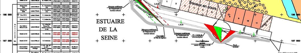
32 Figure 9 Port of Le Havre 32 of 42
33 33 of 42
34 ANNEX F ATON DESIGN FOR THE SEEKANAL ROSTOCK The Seekanal Rostock is a straight channel with buoys from a position 6 miles seawards of the harbour entrance of Rostock/ Warnemünde leading into the mouth of the river Warnow with following design data: 1 WATERWAY Outer part: Length: Width: Depth: Inner part: Length: Width: Depth: 5.7 M m 14.5 m 1.5 M 120 m 14.5 m 2 VESSEL TRAFFIC Total Traffic in the Area in 2006: vessels including Passenger- and Ro/Ro Ferries: 13,000 Cargo vessels: 4,500 Oil Tanker: 1,800 The area is also one of the major places for pleasure and fishing craft in the region. 3 VESSELS DIMENSIONS Terms for two lane traffic passing 120 m width area: 1 Beam < 40 m sum of both passing vessels and Draught < 8.5 m 2 If wind < 6 Bft and both captains accept a two lane traffic passing and Beam < 60 m sum of both passing vessels beams and Draught < 8.5 m 3 vessel with draft > 8,5 m and using the leading line X = 60 m 0.5 * beam of this vessel MAX beam of the meeting vessel X/5 (opposite direction) All other vessels have to pass by one lane traffic under the responsibility of the captain with assistance of VTS. 4 MAXIMUM SIZE OF VESSEL IN SEEKANAL ROSTOCK Length m Beam 32.0 m Draft 10.5 m The channel is narrow in relation to the vessels dimensions. 34 of 42
35 5 AtoN The buoyage system is designed as paired buoys with the following parameters: Buoy separation distance Outer Part m Inner Part 600 m Buoy type Outer Part: deep water light buoy LT 81, steel mooring chains Inner Part: hinge beacon with steel tube, with a minimal swinging circle radius, synchronised lights Buoy size above water level Outer Part: 2.5 x 5 m Inner Part: 1 x 4 m Middle Line Fairway SC EWF EWF SC Figure 10 Example for different types of floating aids on the same fairway : Deep Water Buoy and hinged Beacon Notes 1 EWF = effective width of fairway 2 SC = swinging circle Canal section Figure 11 Seekanal Rostock canal section The inner part of the canal is designed with Hinge Beacons because they have a smaller swinging circle and thus cause less reduction of the effective width of fairway. Additionally there are the following AtoN: Leading Lights over 4 miles, DGPS coverage, VTS coverage, AIS coverage; The Leading Lights are synchronized (same character for front light and rear light). To avoid misleading information in case of failure of one of the lights by mirroring a light with the same character on the water surface and be interpreted as a front light in the wrong place, in case of failure of either the front light or the rear light the other one will also be switched off. This is ensured by connecting the remote control devices of the front light and the rear light. 35 of 42
36 Figure 12 Example for synchronized AtoN : Inner part of Seekanal Rostock The Leading Lights are synchronized with the mole lights and the buoys as shown in Table 2. Table 2 Synchronization of AtoN 1s 2s 3s 4s Flash code Leading lights X On On On Occ. 4s Mole lights at canal entrance X X On On Iso. 4s Articulated lights on buoys X X X On Fl. 4s 36 of 42


37 Figure 13 Sea Chart of a part of the outer and inner channel Seekanal Rostock 37 of 42
38 ANNEX G ATON DESIGN FOR THE APPROACH TO MALMÖ, SWEDEN The Port of Malmö is located on the west coast of the southern part of Sweden. The port is approached from the sea through a channel marked by buoys, light buoys, lights and beacon, on the alignment of leading lights. The channel layout is based on a simulation that was carried out in November 2006 in order to evaluate risk and conditions in terms of vessels types and sizes, tug capacity, port and channel layout. Waterway Outer part Length: Width: Depth: Inner part Length: Width: Depth: 3.9 nm The channel has been widened to 162 m for its full length m 0.6 nm 13.5 m Vessel Traffic Total Traffic in 2008: 1102 arr/dep Vessel Dimensions: 260 x 40 x 12.5 m AtoN The buoyage system is designed as paired buoys. Buoy separation distance Outer part: 0.3 nm Inner part: 0.1 nm All buoys in the channel have synchronized lights with the same frequency at the same time. The light rhythm for the buoys in the channel is Q (0,2s + (0,8s) = 1s) on both sides of the channel. The buoys are of type S-7 (light is 4 m above surface of water). The placement and the synchronised flash on the buoys in the layout is an advantage for safe navigation during darkness as it is much easier to see as the darkness period is very short. The position of the leading light has been optimized according to new channel layout and the blink rate has changed to Oc 6s. There are two lights in line, marking the sides of the channel with the light rhythm Q. The quality of the centre line has improved with a modern high visible light. This improves safety for navigation in restricted visibility. These improvements have made navigation in darkness much safer. Additionally DGPS coverage, VTS, Mandatory pilotage services etc. 38 of 42
39 Figure 14 Outer part of channel - Malmo 39 of 42

40 Figure 15 Inner part of channel - Malmo 40 of 42

41 Figure 16 Entrance to Malmo Harbour 41 of 42

42 Figure 17 Malmo Harbour 42 of 42
IALA Recommendation O-130. Categorisation and Availability Objectives for Short Range Aids to Navigation. Edition 1. December 2004
 International Association of Marine Aids to Navigation and Lighthouse Authorities AISM Association of Internationale de Signalisation Maritime IALA IALA Recommendation O-130 On Categorisation and Availability
The Marking of Offshore Wind Farms. Provide guidance for a response to IALA. M-4 B445.8 &.9 (& B for on-shore wind farms).
.") CSPCWG2-INF 2 The Marking of Offshore Wind Farms Submitted by: Executive Summary: Chairman (from IALA via IHB) Provide guidance for a response to IALA. Does the Related Project reference have any impact
CSPCWG2-INF 2 The Marking of Offshore Wind Farms Submitted by: Executive Summary: Chairman (from IALA via IHB) Provide guidance for a response to IALA. Does the Related Project reference have any impact
Norwegian Coastal Administration (NCA) HSSC November 2015 Busan - Republic of Korea
 HSSC November 2015 Busan - Republic of Korea") Norwegian Coastal Administration (NCA) HSSC7 9-13 November 2015 Busan - Republic of Korea Requirements relating to sector lights for Electronic Navigational Chart (ENC) Product Specifications B E Krosness
Norwegian Coastal Administration (NCA) HSSC7 9-13 November 2015 Busan - Republic of Korea Requirements relating to sector lights for Electronic Navigational Chart (ENC) Product Specifications B E Krosness
ADANI PORTS & SEZ LTD. ++ MUNDRA PORT ++ GENERAL INFORMATION
 ADANI PORTS & SEZ LTD. ++ MUNDRA PORT ++ GENERAL INFORMATION LOCATION Mundra Port is all weather, independent, commercial port with geographical and hydrological advantages on the West Coast of India,
RESOLUTION A.817(19) adopted on 23 November 1995 PERFORMANCE STANDARDS FOR ELECTRONIC CHART DISPLAY AND INFORMATION SYSTEMS (ECDIS)
 adopted on 23 November 1995 PERFORMANCE STANDARDS FOR ELECTRONIC CHART DISPLAY AND INFORMATION SYSTEMS (ECDIS)") A 19/Res.817 15 December 1996 Original: ENGLISH ASSEMBLY 19th session Agenda item 10 RESOLUTION A.817(19) adopted on 23 November 1995 PERFORMANCE STANDARDS FOR ELECTRONIC CHART DISPLAY AND INFORMATION
A 19/Res.817 15 December 1996 Original: ENGLISH ASSEMBLY 19th session Agenda item 10 RESOLUTION A.817(19) adopted on 23 November 1995 PERFORMANCE STANDARDS FOR ELECTRONIC CHART DISPLAY AND INFORMATION
HELSINKI COMMISSION HELCOM SAFE NAV 4/2014 Group of Experts on Safety of Navigation Fourth Meeting Helsinki, Finland, 4 February 2014
 HELSINKI COMMISSION HELCOM SAFE NAV 4/2014 Group of Experts on Safety of Navigation Fourth Meeting Helsinki, Finland, 4 February 2014 Agenda Item 3 Accidents and ship traffic in the Baltic Sea Document
International regulations and guidelines for maritime spatial planning related to safe distances to multiple offshore structures (e.g.
 International regulations and guidelines for maritime spatial planning related to safe distances to multiple offshore structures (e.g. wind farms) Introduction This is a summary of the most important international
IALA World-Wide Academy. Model Course For. Aids to Navigation. Level 2 Technician Training
 AISM Association Internationale de Signalisation Maritime IALA International Association of Marine Aids to Navigation and Lighthouse Authorities IALA World-Wide Academy Model Course For Aids to Navigation
ROYAL VANCOUVER YACHT CLUB
 ROYAL VANCOUVER YACHT CLUB PROPOSED EXPANSION PROJECT NAVIGATION CHANNEL DESIGN COAL HARBOUR Prepared for: Royal Vancouver Yacht Club Prepared by: Typlan Consulting Ltd. March 2016 Page 1 of 17 March 23,
OPERATIONS SEAFARER CERTIFICATION GUIDANCE NOTE SA MARITIME QUALIFICATIONS CODE. Deck: Chart Work
 Page 1 of 6 Compiled by Approved by Chief Examiner Syllabus Committee: 26 February 2013 OPERATIONS SEAFARER CERTIFICATION GUIDANCE NOTE SA MARITIME QUALIFICATIONS CODE Deck: Chart Work Page 2 of 6 COLUMN
CHAPTER I SUEZ CANAL NAVIGATION FEATURES SECTION 1 APPROACHES
 CHAPTER I SUEZ CANAL NAVIGATION FEATURES --------------------- SECTION 1 APPROACHES Art. 8 - PORT SAID: (See Admiralty Charts No. 234, 240 & 241 GENERAL: The Vessels coming from see fifteen miles before
THE SYLLABUS FOR WRITTEN EXAMINATION PILOT'S FOURTH CLASS LICENCE (TEES AND HARTLEPOOL) AND
 AND") PD TEESPORT CONSERVANCY DIVISION HARBOUR MASTER'S OFFICE THE SYLLABUS FOR WRITTEN EXAMINATION IN RESPECT OF A PILOT'S FOURTH CLASS LICENCE (TEES AND HARTLEPOOL) AND PILOTAGE EXEMPTION CERTIFICATE (Issued
PD TEESPORT CONSERVANCY DIVISION HARBOUR MASTER'S OFFICE THE SYLLABUS FOR WRITTEN EXAMINATION IN RESPECT OF A PILOT'S FOURTH CLASS LICENCE (TEES AND HARTLEPOOL) AND PILOTAGE EXEMPTION CERTIFICATE (Issued
Preventing Damage to Harbour Facilities and. Ship Handling in Harbours PART 2 INDEX
 Preventing Damage to Harbour Facilities and Ship Handling in Harbours PART 2 INDEX 1 Vessel handling is based on the basic knowledge that a vessel floats in the water and returns to its original position
LES CAHIERS D APPRENTISSAGE MARITIME AIDS TO NAVIGATION AIDS TO NAVIGATION IALA MARITIME BUOYAGE SYSTEM. Page 1 sur 22
 IALA MARITIME BUOYAGE SYSTEM LES CAHIERS D APPRENTISSAGE MARITIME Page 1 sur 22 GENERAL PRINCIPLES OF THE SYSTEM The responsibility for safe navigation resides with the mariner, through the appropriate
PERFORMANCE STANDARDS FOR ELECTRONIC CHART DISPLAY AND INFORMATION SYSTEMS (ECDIS) [IMO Resolutions A.817 (19), MSC.64 (67) and MSC.
 [IMO Resolutions A.817 (19), MSC.64 (67) and MSC.") 1 PERFORMANCE STANDARDS FOR ELECTRONIC CHART DISPLAY AND INFORMATION SYSTEMS (ECDIS) [IMO Resolutions A.817 (19), MSC.64 (67) and MSC.86 (70)] (amended March 1999) Note: The IMO Performance Standards for
1 PERFORMANCE STANDARDS FOR ELECTRONIC CHART DISPLAY AND INFORMATION SYSTEMS (ECDIS) [IMO Resolutions A.817 (19), MSC.64 (67) and MSC.86 (70)] (amended March 1999) Note: The IMO Performance Standards for
IALA Recommendation E-110. for the. Rhythmic Characters of Lights on Aids to Navigation Edition 2 December Edition 1 Published May 1998
 International Association of Marine Aids to Navigation and Lighthouse Authorities AISM Association of Internationale de Signalisation Maritime IALA IALA Recommendation E-110 for the Rhythmic Characters
IMO RESOLUTION A.960(23) Adopted 5 December 2003 (Agenda item 17)
 Adopted 5 December 2003 (Agenda item 17)") INTERNATIONAL MARITIME ORGANIZATION E IMO ASSEMBLY 23rd session Agenda item 17 A 23/Res.960 5 March 2004 Original: ENGLISH RESOLUTION A.960(23) Adopted 5 December 2003 (Agenda item 17) RECOMMENDATIONS
INTERNATIONAL MARITIME ORGANIZATION E IMO ASSEMBLY 23rd session Agenda item 17 A 23/Res.960 5 March 2004 Original: ENGLISH RESOLUTION A.960(23) Adopted 5 December 2003 (Agenda item 17) RECOMMENDATIONS
Presentation Library for Inland ECDIS
 Edition 2.0 1.6.2006 Standard Electronic Chart Display and Information System for Inland Navigation Inland ECDIS for Inland ECDIS In addition to the IHO-S-52 Edition 2.0 IES 20-Section 3 PresLib.doc Page
RESOLUTION MSC.94(72) (adopted on 22 May 2000) PERFORMANCE STANDARDS FOR NIGHT VISION EQUIPMENT FOR HIGH-SPEED CRAFT (HSC)
 (adopted on 22 May 2000) PERFORMANCE STANDARDS FOR NIGHT VISION EQUIPMENT FOR HIGH-SPEED CRAFT (HSC)") MSC 72/23/Add.1 RESOLUTION MSC.94(72) EQUIPMENT FOR HIGH-SPEED CRAFT (HSC) THE MARITIME SAFETY COMMITTEE, RECALLING Article 28(b) of the Convention on the International Maritime Organization concerning
MSC 72/23/Add.1 RESOLUTION MSC.94(72) EQUIPMENT FOR HIGH-SPEED CRAFT (HSC) THE MARITIME SAFETY COMMITTEE, RECALLING Article 28(b) of the Convention on the International Maritime Organization concerning
National Maritime Center
 National Maritime Center Providing Credentials to Mariners Able Seaman Unlimited, Limited, Special, Special OSV, Sail, Fishing Industry (Sample Examination) Page 1 of 17 Choose the best answer to the following
COAST GUARD ADVISORY NOTICE (CGAN ) To: Distribution Date: September 1, 2017
 To: Distribution Date: September 1, 2017") Commander United States Coast Guard Sector New York 212 Coast Guard Drive Staten Island, NY 10305 Staff Symbol: (spw) Phone: (718) 354-2353 Fax: (718) 354-4190 COAST GUARD ADVISORY NOTICE (CGAN 2017-016)
Commander United States Coast Guard Sector New York 212 Coast Guard Drive Staten Island, NY 10305 Staff Symbol: (spw) Phone: (718) 354-2353 Fax: (718) 354-4190 COAST GUARD ADVISORY NOTICE (CGAN 2017-016)
Chart Features Maritime maps and Admiralty charts have these features:
 Introduction to Charts A chart or map of the area is an important safety item to carry on board. It allows the Master to obtain knowledge of the area to be travelled, and indicates the navigable channels
SAFETY OF NAVIGATION OPERATING ANOMALIES IDENTIFIED WITHIN ECDIS
 E 4 ALBERT EMBANKMENT LONDON SE1 7SR Telephone: +44 (0)20 7735 7611 Fax: +44 (0)20 7587 3210 SN.1/Circ.312 9 July 2012 SAFETY OF NAVIGATION OPERATING ANOMALIES IDENTIFIED WITHIN ECDIS 1 The Sub-Committee
properly applied assessment in the use.1 landmarks.1 approved in-service of ECDIS is not experience The primary method of fixing required for those
 STCW Code Table A-II/3 Specification of minimum standard of for officers in charge of a navigational watch and for masters on ships of less than 500 gross tonnage engaged on near-coastal voyages Ref: https://www.edumaritime.net/stcw-code
Gorgon - Pilotage - Passage Plan Materials Offloading Facility (MOF) to PBG
 to PBG") Gorgon - Pilotage - Passage Plan Materials Offloading Facility (MOF) to PBG 1.0 Introduction Vessels transiting within port limits from the Materials Offloading Facility (MOF) to the Barrow Island Pilot
Gorgon - Pilotage - Passage Plan Materials Offloading Facility (MOF) to PBG 1.0 Introduction Vessels transiting within port limits from the Materials Offloading Facility (MOF) to the Barrow Island Pilot
Aids to navigation can include buoys, day beacons, range markers, and lighthouses.
 This boating safety course manual has been approved by Transport Canada strictly on the basis that it meets the minimum requirements of basic boating safety knowledge set out in Transport Canada s Boating
Gorgon - Pilotage - Passage Plan PBG to Materials Offloading Facility (MOF)
") 1.0 Introduction Vessels transiting within port limits from the Barrow Island Pilot Boarding Ground (PBG) to the require an approved passage plan which can be shared between Pilots and vessel Masters.
1.0 Introduction Vessels transiting within port limits from the Barrow Island Pilot Boarding Ground (PBG) to the require an approved passage plan which can be shared between Pilots and vessel Masters.
EBA Position Statement AIS Virtual Aids to Navigation
 EBA Position Statement AIS Virtual Aids to Navigation Document date: 17 October 2015 Latest update: 9 December 2015 Executive Summary The European Boating Association 1 (EBA) recognises the value of Automatic
S-44 edition 5 The IHO s New Standard For Hydrographic Surveys Chris Howlett Head of Seabed Data Centre United Kingdom Hydrographic Office
 S-44 edition 5 The IHO s New Standard For Hydrographic Surveys Chris Howlett Head of Seabed Data Centre United Kingdom Hydrographic Office Chairman of IHO Working Group that created S-44 edition 5 S-44
REGION B ONLY. Figure Figure Figure Figure Figure Figure Figure Figure 10.60
 221 REGION B ONLY 10.5 LATERAL MARKS 10.5.1 Description of Lateral marks Port hand marks Shape: pillar buoy (Figures 10.53 and 10.54), can lighted buoy (Figures 10.55 and 10.56) or not lighted (Figures
Marine farm guidelines: navigational safety
 Marine farm guidelines: navigational safety This guideline is for those involved in marine farms, particularly regarding aids to navigation and associated matters of navigational safety DRAFT Marine farm
Pilotage Directions 2017
 Pilotage Directions 2017 1. Commencement These Pilotage Directions shall come into force on 31 st August 2017 on which date the existing Pilotage Directions are revoked. 2. Short Title These Pilotage Directions
GUIDELINES FOR NAVIGATION UNDER THE CONFEDERATION BRIDGE
 (12/2009) GUIDELINES FOR NAVIGATION UNDER THE CONFEDERATION BRIDGE REVISION 1 DECEMBER 2009 Responsible Authority The Regional Director Marine Safety Atlantic Region is responsible for this document, including
DUBLIN PORT COMPANY PILOTAGE BYE-LAWS. 1st July Dublin Port Company Pilotage Bye-Laws, 1 st July 2018 Page 1
 DUBLIN PORT COMPANY PILOTAGE BYE-LAWS 1st July 2018 Dublin Port Company Pilotage Bye-Laws, 1 st July 2018 Page 1 Contents PILOTAGE BYE-LAWS... 3 1) Interpretation... 3 2) Compulsory Pilotage and Exempted
Convention on the International Regulations for Preventing Collisions at Sea, 1972 (COLREGs) EXPLANATORY NOTES
 EXPLANATORY NOTES") Convention on the International Regulations for Preventing Collisions at Sea, 1972 (COLREGs) EXPLANATORY NOTES Adoption: 20 October 1972 Entry into force: 15 July 1977 Introduction Amendment procedure
Convention on the International Regulations for Preventing Collisions at Sea, 1972 (COLREGs) EXPLANATORY NOTES Adoption: 20 October 1972 Entry into force: 15 July 1977 Introduction Amendment procedure
Paper for consideration by ENC Working Group. Use of AU6 ENC cells as an option for Bathymetric ENCs (benc)
") Paper for consideration by ENC Working Group Use of AU6 ENC cells as an option for Bathymetric ENCs (benc) Submitted by: Alvaro Sanchez (AHS) Executive Summary: Compilation of high density bathymetric
Paper for consideration by ENC Working Group Use of AU6 ENC cells as an option for Bathymetric ENCs (benc) Submitted by: Alvaro Sanchez (AHS) Executive Summary: Compilation of high density bathymetric
RESOLUTION MSC.161(78) (adopted on 17 May 2004) AMENDMENTS TO THE EXISTING MANDATORY SHIP REPORTING SYSTEM "THE TORRES STRAIT AND INNER ROUTE OF THE
 (adopted on 17 May 2004) AMENDMENTS TO THE EXISTING MANDATORY SHIP REPORTING SYSTEM THE TORRES STRAIT AND INNER ROUTE OF THE") MSC 78/26/Add.2 RESOLUTION MSC.161(78) REPORTING SYSTEM THE TORRES STRAIT AND INNER ROUTE OF THE GREAT BARRIER REEF THE MARITIME SAFETY COMMITTEE, RECALLING Article 28(b) of the Convention on the International
MSC 78/26/Add.2 RESOLUTION MSC.161(78) REPORTING SYSTEM THE TORRES STRAIT AND INNER ROUTE OF THE GREAT BARRIER REEF THE MARITIME SAFETY COMMITTEE, RECALLING Article 28(b) of the Convention on the International
Port Sections Guide Section 01
 s Guide 01 Cow Bay Marina Date 10/1/2016 Position (lat / lon) Minimum controlled water depth Chart datum Range of water densities Tidal range alongside Bottom type Dredging regime Distance pilot station
Gorgon - Pilotage - Passage Plan - PBG to Gorgon Marine Terminal - Alternative Route
 1.0 Introduction This work instruction outlines the passage plan to be used by vessels transiting from the Port of Barrow Island PBG to the Gorgon Marine Terminal, via the alternative route, with a Pilot
Uncontrolled document if printed.
 APPENDIX 3 APPRENTICE PILOT S TRAINING SYLLABUS Issue Date: 16 th March, 2010 Date of Revision: 22nd May, 2013 Revision #2 i THE PURPOSE OF THIS SYLLABUS The purpose of this training syllabus is to ensure
Note to Shipbuilders, shipowners, ship Managers and Masters. Summary
 MARINE GUIDANCE NOTE MGN 301 (M+F) Manoeuvring Information on Board Ships Note to Shipbuilders, shipowners, ship Managers and Masters This note supersedes Marine Guidance Note MGN 201 (M+F) Summary The
WORK-REST REQUIREMENTS FOR PILOTS
 AN ORDER OF THE BOARD OF PILOT COMMISSIONERS FOR THE PORT OF CORPUS CHRISTI AUTHORITY REGARDING WORK-REST REQUIREMENTS FOR PILOTS AND COMBINED BEAM RESTRICTION Whereas, the current Rules and Regulations
A buoy, for example is an aid to navigation. Aids to navigation include many types of buoys as well as day beacons, range markers, and lighthouses.
 This online study guide has been approved by Transport Canada strictly on the basis that it meets the requirements of the Standard for Pleasure Craft Operator Testing over the Internet (TP 15080E) and
GENERAL LIMITATIONS AND RESTRICTIONS. LNGC Temporary Exemption (Effective August 21, 2018)
") RULES AND REGULATIONS GOVERNING PILOTS AND PILOTAGE ON THE CORPUS CHRISTI SHIP CHANNEL EFFECTIVE AUGUST 1, 2013 AMENDED EFFECTIVE MAY 13, 2014 AMENDED EFFECTIVE OCTOBER 1, 2014 AMENDED EFFECTIVE JANUARY
RULES AND REGULATIONS GOVERNING PILOTS AND PILOTAGE ON THE CORPUS CHRISTI SHIP CHANNEL EFFECTIVE AUGUST 1, 2013 AMENDED EFFECTIVE MAY 13, 2014 AMENDED EFFECTIVE OCTOBER 1, 2014 AMENDED EFFECTIVE JANUARY
ANNEX 2 RESOLUTION MEPC.124(53) Adopted on 22 July 2005 GUIDELINES FOR BALLAST WATER EXCHANGE (G6) THE MARINE ENVIRONMENT PROTECTION COMMITTEE,
 Adopted on 22 July 2005 GUIDELINES FOR BALLAST WATER EXCHANGE (G6) THE MARINE ENVIRONMENT PROTECTION COMMITTEE,") Page 1 RESOLUTION MEPC.124(53) Adopted on 22 July 2005 GUIDELINES FOR BALLAST WATER EXCHANGE (G6) THE MARINE ENVIRONMENT PROTECTION COMMITTEE, RECALLING Article 38(a) of the Convention on the International
Page 1 RESOLUTION MEPC.124(53) Adopted on 22 July 2005 GUIDELINES FOR BALLAST WATER EXCHANGE (G6) THE MARINE ENVIRONMENT PROTECTION COMMITTEE, RECALLING Article 38(a) of the Convention on the International
Outcome of the discussion with other HSSC WG on contribution to the MSP MSP development work
 NIPWG 4-43.1 Submitted by: Executive Summary: Paper for Consideration by NIPWG IMO e-navigation Hydrographic Services Related Documents: HSSC7 (action item 7/35) Related Projects: IMO e-navigation NIPWG
INTERNATIONAL HYDROGRAPHIC SURVEY STANDARDS
 INTERNATIONAL HYDROGRAPHIC SURVEY STANDARDS by Gerald B. MILLS 1 I. Background The International Hydrographic Organization (IHO) traces its origin to the establishment of the International Hydrographic
PORT INFO GENERAL BERTH INFO
 s ervices SHIPWRIGHT WWW.SHIPWRIGHTSERVICES.CO.ZA 9 DE DUINE CLOSE, BLUEWATERBAY, SALDANHA, 7395, WESTERN CAPE, SOUTH AFRICA TEL. +27 71 040 6022 EMAIL. DERICK@SHIPWRIGHTSERVICES.CO.ZA PORT INFO GENERAL
2005 ABC. Chapter 3 Part 2. Navigating with ATON's. Revision to D-13 Local Notes. Instructor Notes for Mike Brough. Mike Brough
 2005 ABC Chapter 3 Part 2 Navigating with ATON's Revision to D-13 Local Notes Instructor Notes for Mike Brough Mike Brough June 24 2008 June 24 2008 Slide 1 June 24 2008 New graphics Navigating on Water
National Maritime Center
 National Maritime Center Providing Credentials to Mariners (Sample Examination) Page 1 of 16 Choose the best answer to the following Multiple Choice Questions. 1. On U.S. charts, you can tell if a named
ROUTEING MEASURES OTHER THAN TRAFFIC SEPARATION SCHEMES
 E 4 ALBERT EMBANKMENT LONDON SE1 7SR Telephone: +44 (0)20 7735 7611 Fax: +44 (0)20 7587 3210 SN.1/Circ.317 4 December 2012 ROUTEING MEASURES OTHER THAN TRAFFIC SEPARATION SCHEMES 1 The Maritime Safety
Code Of Practice For Towage Operations In The Port of St Helier (Towage Guidelines)
") Code Of Practice For Towage Operations In The Port of St Helier (Towage Guidelines) This Code Covers The Use Of Tugs And Towage In The Port Of St Helier Page number Contents 2 Introduction 3 Communication
Code Of Practice For Towage Operations In The Port of St Helier (Towage Guidelines) This Code Covers The Use Of Tugs And Towage In The Port Of St Helier Page number Contents 2 Introduction 3 Communication
Gorgon Pilotage Passage Plan - PBG to Gorgon Marine Terminal Primary Route
 Gorgon Pilotage Passage Plan - PBG to Gorgon Marine Terminal Primary Route 1.0 Introduction Vessels transiting within port limits from the Barrow Island Outer Pilot Boarding Ground (PBG) to the Gorgon
TECHNICAL INFORMATION BOLLARDPULL TRIALCODE. ForTugs with SteerpropPropulsion. Steerprop
 TECHNICAL INFORMATION BOLLARDPULL TRIALCODE ForTugs with SteerpropPropulsion Steerprop A Skogman / 22 March 2001 BOLLARD PULL TRIAL CODE FOR TUGS This Bollard Pull Trial Code is established to define the
Transport Infrastructure Act 1994 Gladstone Ports Corporation. Port Notice 04/17 LNG Vessel Operating Parameters
 Transport Infrastructure Act 1994 Gladstone Ports Corporation Port Notice 04/17 LNG Vessel Operating Parameters 1. These operating parameters have been developed based on navigation simulations with LNG
 ON SHIPS OF 200 GRT/500 GT OR MORE Assessment Sheets Enclosure (1) to CG-543 Policy Letter 11-07 ASSESSMENT NO. OICNW-1-1A COMPETENCE: Plan and conduct a passage and determine position KNOWLEDGE, UNDERSTANDING
GENERAL LIMITATIONS AND RESTRICTIONS. Draft Restrictions
 RULES AND REGULATIONS GOVERNING PILOTS AND PILOTAGE ON THE CORPUS CHRISTI SHIP CHANNEL EFFECTIVE AUGUST 1, 2013 AMENDED EFFECTIVE MAY 13, 2014 AMENDED EFFECTIVE OCTOBER 1, 2014 I GENERAL The Rules and
MAC Transit Advisories as of April 30, 2018
 MAC Transit Advisories as of April 30, 2018 The Mariners Advisory Committee for the Bay and River Delaware was established in October 1964. Its members and associate members are mainly comprised of master
SOLAS requirements for nonpassenger ships 300 or above but less than 500 gross tonnage
 SOLAS requirements for nonpassenger ships 300 or above but less than 500 gross tonnage Guidance for owners, masters and surveyors for ships undertaking international voyages SOLAS requirements applied
Delaware River Vessel Reporting System Mariners Advisory Committee For
 Delaware River Vessel Reporting System Mariners Advisory Committee For the Bay and River Delaware The Mariner's Advisory Committee is comprised of Master Mariners, River Pilots, and concerns itself with
NIGERIAN NOTICES TO MARINERS November 2017 EDITION PUBLISHED BY THE HYDROGRAPHIC OFFICE LAGOS. Notice 01 November 2017 Supplied Gratis
 NIGERIAN NOTICES TO MARINERS November 2017 EDITION PUBLISHED BY THE HYDROGRAPHIC OFFICE LAGOS Notice 01 November 2017 Supplied Gratis November 2017 CONTENTS I II Explanatory Notes and Index Nigerian Navy
Harbourmaster s Office Tamaki River. Navigation Safety Operating Requirements 2014
 Harbourmaster s Office Tamaki River Navigation Safety Operating Requirements 2014 Auckland Council Harbourmaster s Office TAMAKI RIVER Navigation Safety Operating Requirements FOREWARD The purpose of these
iii) Satisfactory completion of approved training in the following:
 Satisfactory completion of approved training in the following:") Enclosure (1) to NVIC 13-14 DISCUSSION OF QUALIFICATION REQUIREMENTS FOR MASTER AND OFFICER IN CHARGE OF A NAVIGATIONAL WATCH ON VESSELS OF LESS THAN 500 GT LIMITED TO NEAR-COASTAL WATERS 1. GENERAL. This
Enclosure (1) to NVIC 13-14 DISCUSSION OF QUALIFICATION REQUIREMENTS FOR MASTER AND OFFICER IN CHARGE OF A NAVIGATIONAL WATCH ON VESSELS OF LESS THAN 500 GT LIMITED TO NEAR-COASTAL WATERS 1. GENERAL. This
Chapter 8. Port hand buoy. Starboard hand buoy. Canadian Aids to Navigation System (CANS) 8.1 Introduction. 8.2 Lateral Buoys
 8.1 Introduction. 8.2 Lateral Buoys") Chapter 8 Canadian Aids to Navigation System (CANS) 8.1 Introduction Various buoys, beacons and signs are known as "Aids to Navigation" or "Navigation Aids". They are devices or systems external to the
Chapter 8 Canadian Aids to Navigation System (CANS) 8.1 Introduction Various buoys, beacons and signs are known as "Aids to Navigation" or "Navigation Aids". They are devices or systems external to the
 Page 1 of 6 Nav-Aid Basics Unlike the roads and highways that we drive on, the waterways we go boating on do not have road signs that tell us our location, the route or distance to a destination, or of
NAEST(M) training Course Structure and Session Objectives. Day Introduction and enrolment
 training Course Structure and Session Objectives. Day Introduction and enrolment") NAEST(M) training Course Structure and Session Objectives Day 1 0830-0930 Introduction and enrolment 0930-1330 Effective Bridge Procedures & Rule of the Road Lecturer will go through the PowerPoint on
NAEST(M) training Course Structure and Session Objectives Day 1 0830-0930 Introduction and enrolment 0930-1330 Effective Bridge Procedures & Rule of the Road Lecturer will go through the PowerPoint on
National Maritime Center
 National Maritime Center Providing Credentials to Mariners (Sample Examination) Page 1 of 13 Choose the best answer to the following Multiple Choice Questions. 1. What is the approximate geographic range
IALA Buoyage System and Visual Aids to Navigation. by Aleksandr D. Pipchenko
 IALA Buoyage System and Visual Aids to Navigation by Aleksandr D. Pipchenko IALA buoyage regions chart Which types of marks are provided by the system? Six types of marks provided by the system: Lateral
DUKC Chart Overlay. Presentation to IHO TWL and DQ Working Groups Wollongong, March 2014
 DUKC Chart Overlay Presentation to IHO TWL and DQ Working Groups Wollongong, March 2014 Outline Who is OMC? DUKC description & methodology. DUKC Chart Overlay concept. Chart Overlay application example.
Automatic Identification System (AIS) Class B - coding for non-solas vessels.
 Class B - coding for non-solas vessels.") MARINE INFORMATION NOTE MIN 321 (M+F) Automatic Identification System (AIS) Class B - coding for non-solas vessels. Notice to all Shipowners, Masters, Small Craft Vessel Operators, Leisure Vessel Users,
MARINE INFORMATION NOTE MIN 321 (M+F) Automatic Identification System (AIS) Class B - coding for non-solas vessels. Notice to all Shipowners, Masters, Small Craft Vessel Operators, Leisure Vessel Users,
Abstract. Introduction
 Computer assisted analysis of Aviles Port extension: hydraulic conditions, navigation and training of pilots J.R. Iribarren & J.M. Montero Port Research Program, CEPYC-CEDEX, Antonio Lopez, 81. 28026 Madrid,
Gorgon - Pilotage - Passage Plan - Gorgon Marine Terminal to PBG Alternative Route
 Gorgon - Pilotage - Passage Plan - Gorgon Operating Procedure - Gorgon - Pilotage - Passage Plan - Gorgon 1.0 Introduction Vessels transiting within port limits from the Gorgon Marine Terminal
FULL SCALE MEASUREMENT OF DYNAMIC SHIP MOTIONS AND SQUAT
 FULL SCALE MEASUREMENT OF DYNAMIC SHIP MOTIONS AND SQUAT Mr. Gary Rolph Chief Hydrographic Surveyor Port of Brisbane Corporation Mr. Peter Rumball Surveyor Port of Brisbane Corporation Dr. Terry O'Brien
Rule Conduct of vessels in restricted visibility
 Section III Rule 19 -- Conduct of vessels in restricted visibility (a) This Rule applies to vessels not in sight of one another when navigating in or near an area of restricted visibility. (b) Every vessel
Forth Ports Limited. Ruling Depths & Under Keel Clearances
 Forth Ports Limited - Forth Vessels are scheduled into / out of ports on the Forth & Tay in accordance with the under keel clearance criteria specified in this section of the Marine Guidelines & Port Information.
HOUSTON SEA CHEST CLOGGING SURVEY
 HOUSTON SEA CHEST CLOGGING SURVEY *** YOUR HELP IS VOLUNTARY AND ANONYMOUS*** ***PLEASE DO NOT INCLUDE VESSEL NAME OR NUMBER *** IT IS 2015 MENHADEN SEASON IN THE HOUSTON SHIP CHANNEL To Vessel Master/Chief
The role of UKCM now and the future
 The role of UKCM now and the future NAV18 Torres Strait use case omcinternational.com Who is OMC International? Inventor (1993) and sole supplier of DUKC (>160,000 deep draft transits without incident)
ECDIS Familiarisation Training
 Chapter 4 ECDIS Familiarisation Training The convention related to the qualifications of seafarers responsible for ship operation is STCW (International Convention on Standards of Training, Certification
AK-APC-NTV Operating Procedures for Cargo and Passenger Non Tank Vessels Transiting and Operating in Alaska Waters December 26, 2015
 AK-APC-NTV Operating Procedures for Cargo and Passenger Non Tank Vessels Transiting and Operating in Alaska Waters December 26, 2015 The Alternative Planning Criteria (APC) Operating Procedures were developed
What s Up in Navigation Displays?
 What s Up in Navigation Displays? Captain PAUL CHAPMAN paul.chapman@compassadjuster.com.au 2009 What s up in Navigation Displays? Captain Paul Chapman Situation Awareness When following a passage plan,
Competency framework for Skipper Coastal / Offshore. Competency framework for Skipper Coastal/ Offshore
 Competency framework for Skipper Coastal/ Offshore Table of Contents... 1... 1 Function: Safety at the management level... 11 Manage safety aboard a coastal and vessel... 11 Competency framework for Skipper
Port of Port Elizabeth Information
 LOCATION Latitude 34º 01 S Longitude 25º 42 E PILOTAGE Pilotage is compulsory. Rendezvous point is 2.2 nautical miles NE of the port entrance on the leading lights. Pilot transfer is by pilot boat, unless
APC Operating Procedures Oil Tankers
 APC Operating Procedures Oil Tankers August 2013 The APC Operating Procedures were developed to aid the Master and Operator of oil tankers in ensuring all aspects of the APC are complied with when transiting
III Code. TRACECA Maritime Safety and Security IMSAS workshop Kiev (Ukraine) III Code. Dr. Jens U. Schröder-Hinrichs
 III Code. Dr. Jens U. Schröder-Hinrichs") III Code III Code III Code TRACECA Maritime Safety and Security IMSAS workshop Kiev (Ukraine) Dr. Jens U. Schröder-Hinrichs IMSAS workshop Kiev Agenda 1 2 3 4 5 6 7 8 9 Introduction Background to IMSAS
III Code III Code III Code TRACECA Maritime Safety and Security IMSAS workshop Kiev (Ukraine) Dr. Jens U. Schröder-Hinrichs IMSAS workshop Kiev Agenda 1 2 3 4 5 6 7 8 9 Introduction Background to IMSAS
UNITED NEW YORK SANDY HOOK PILOTS BENEVOLENT ASSOCIATION AND UNITED NEW JERSEY SANDY HOOK PILOTS BENEVOLENT ASSOCIATION
 UNITED NEW YORK SANDY HOOK PILOTS BENEVOLENT ASSOCIATION AND UNITED NEW JERSEY SANDY HOOK PILOTS BENEVOLENT ASSOCIATION TO: All Shipping Agents and Interested Parties January 19, 2017 SUBJECT: Anchorage
5.0 Channel Design and Alternatives
 5.0 Channel Design and Alternatives The dimensions of the navigational areas such as approach channel, manoeuvring areas, anchorage, etc. are based on the type and size of the vessel envisaged to visit
ANNEX 24 RESOLUTION MSC.232(82) (adopted on 5 December 2006)
 (adopted on 5 December 2006)") RESOLUTION MSC.232(82) (adopted on 5 December 2006) ADOPTION OF THE REVISED PERFORMANCE STANDARDS FOR ELECTRONIC CHART DISPLAY AND INFORMATION SYSTEMS (ECDIS) THE MARITIME SAFETY COMMITTEE, RECALLING Article
RESOLUTION MSC.232(82) (adopted on 5 December 2006) ADOPTION OF THE REVISED PERFORMANCE STANDARDS FOR ELECTRONIC CHART DISPLAY AND INFORMATION SYSTEMS (ECDIS) THE MARITIME SAFETY COMMITTEE, RECALLING Article
The LA/LB Harbors handle more than 5,500 commercial vessel arrivals per year (excluding local coastwise and Catalina Island traffic).
.") X. SMALL CRAFT For the purpose of the Los Angeles and Long Beach Harbor Safety Plan, pleasure vessels, commercial fishing vessels and sportfishing boats are designated as small craft. A. BACKGROUND: The
X. SMALL CRAFT For the purpose of the Los Angeles and Long Beach Harbor Safety Plan, pleasure vessels, commercial fishing vessels and sportfishing boats are designated as small craft. A. BACKGROUND: The
SLOP RECEPTION AND PROCESSING FACILITIES
 RULES FOR CLASSIFICATION OF SHIPS NEWBUILDINGS SPECIAL SERVICE AND TYPE ADDITIONAL CLASS PART 5 CHAPTER 8 SLOP RECEPTION AND PROCESSING FACILITIES JANUARY 2011 CONTENTS PAGE Sec. 1 General Requirements...
MARINE SAFETY PLAN
 PORT MARINE SAFETY CODE MARINE SAFETY PLAN 2015-2017 Introduction As required at article 3.20 of the Port Marine Safety Code (PMSC), the Port of London Authority (PLA) publishes its Marine Safety Plan
A real time vessel air gap monitoring system
 Journal of Physics: Conference Series A real time vessel air gap monitoring system To cite this article: D McStay and K Thabeth 2009 J. Phys.: Conf. Ser. 178 012038 View the article online for updates
U.S. Aids To Navigation System Brochure U.S. Coast Guard, Office of Aids to Navigation (202) ,
 ,") AIDS TO NAVIGATION Learning Objectives: As a result of this session the participant should: Understand the principal buoyage systems in the United States. Become aware of the characteristics of the buoy
AIDS TO NAVIGATION Learning Objectives: As a result of this session the participant should: Understand the principal buoyage systems in the United States. Become aware of the characteristics of the buoy
How To Enter Kushiro Port and Things To Be Aware of When Entering
 How To Enter Kushiro Port and Things To Be Aware of When Entering 1.How to enter Kushiro Port (1)How to enter the East Area When entering the port from Nemuro, navigate while maintaining a safe distance
PORTS AUSTRALIA. PRINCIPLES FOR GATHERING AND PROCESSING HYDROGRAPHIC INFORMATION IN AUSTRALIAN PORTS (Version 1.5 November 2012)
") PORTS AUSTRALIA PRINCIPLES FOR GATHERING AND PROCESSING HYDROGRAPHIC INFORMATION IN AUSTRALIAN PORTS (Version 1.5 November 2012) PREFACE These Principles have been prepared by the Hydrographic Surveyors
PORTS AUSTRALIA PRINCIPLES FOR GATHERING AND PROCESSING HYDROGRAPHIC INFORMATION IN AUSTRALIAN PORTS (Version 1.5 November 2012) PREFACE These Principles have been prepared by the Hydrographic Surveyors
The risk assessment of ships manoeuvring on the waterways based on generalised simulation data
 Safety and Security Engineering II 411 The risk assessment of ships manoeuvring on the waterways based on generalised simulation data L. Gucma Maritime University of Szczecin, Poland Abstract This paper
2 Boating Rules and Regulations... 73
 Contents at a Glance Chapter 1 Boat Design and Construction Chapter 2 Boating Rules and Regulations Chapter 3 Navigation Rules (ColRegs) Chapter 4 Boat Operating and Seamanship Chapter 5 Piloting and Navigation
PILOTAGE DIRECTIONS REVIEWED DECEMBER 2016
 PILOTAGE DIRECTIONS REVIEWED DECEMBER 2016 REVISION LIST Revision No. Date Details Approved by: Original All sections 12 Dec 2013 First edition of C W Brand v1.0 Pilotage Directions Revision 2 all sections
Minimum standard of competence for Master (STCW Reg II/2)
") Minimum standard of for Master (STCW Reg II/2) Function: Navigation at the management level Column 1 Column 2 Column 3 Column 4 Plan a voyage and Voyage planning and Examination and The equipment, charts
Minimum standard of for Master (STCW Reg II/2) Function: Navigation at the management level Column 1 Column 2 Column 3 Column 4 Plan a voyage and Voyage planning and Examination and The equipment, charts
Plot the Path into the Harbor
 Plot the Path into the Harbor By Mary Anne Otten, Rudyard Area Schools and Joan Chadde, Michigan Technological University Subject/Grade: Grade 3 6, Math, Social Studies, Science Duration: 35 minutes Lesson
Wheatstone Marine Operations - Pilotage - Passage Plan - Onslow Port Limit to WMT
 Wheatstone Marine Operations - Pilotage - Passage Plan - Onslow Port Limit to WMT 1.0 INTRODUCTION Vessels entering the Port of Ashburton require an approved berth to berth passage plan in accordance with