Trials Bike Frame Concept
|
|
|
- Lynette Waters
- 6 years ago
- Views:
Transcription

1 Western Michigan University ScholarWorks at WMU Honors Theses Lee Honors College Trials Bike Frame Concept David Boboltz Western Michigan University, Rob Harmer Western Michigan University, Caleb Vanderveen Western Michigan University Follow this and additional works at: Part of the Mechanical Engineering Commons Recommended Citation Boboltz, David; Harmer, Rob; and Vanderveen, Caleb, "Trials Bike Frame Concept" (2007). Honors Theses This Honors Thesis-Open Access is brought to you for free and open access by the Lee Honors College at ScholarWorks at WMU. It has been accepted for inclusion in Honors Theses by an authorized administrator of ScholarWorks at WMU. For more information, please contact


2 Western Michigan University The Carl and Winifred Lee Honors College THE CARL AND WINIFRED LEE HONORS COLLEGE CERTIFICATE OF ORAL DEFENSE OF HONORS THESIS David Boboltz, having been admitted to the Carl and Winifred Lee Honors College in Fall 2002, successfully presented the Lee Honors College Thesis on April 17, The title of the paper is: "Development of Prototype Trials Frame" Dr. Dennis VandenBrink, Mechanical and Aeronautical Engineering Dr. Bade Shrestha, Mechanical and Aeronautical Engineering Dr. Rameshwar Sharma, Mechanical and Aeronautical Engineering 1903W. Michigan Ave., Kalamazoo, Ml PHONE: (269) FAX: (269)
3 Western Michigan University Senior Design Project Report Trials Bike Frame Concept ME April 17, 2007 By David Boboltz - ME Rob Harmer - AAE Caleb Vanderveen - AAE Faculty Mentor Dr. Dennis Vandenbrink
4 Project Summary Development of a Concept Trials Frame was a mechanical engineering design project that developed a new bicycle frame that has the strength and durability to be used for trials bike riding. The scope of the project was placed solely on the bicycle's frame. Current frames were analyzed based on their strength, durability, stiffness, weight, and appearance. These factors were ranked for importance and became the performance targets for the new frame. Several designs that utilize elastic strain energy to increase performance were brainstormed. Following SolidWorks modeling, equivalent impact loads were calculated using several analytical methods. These loads were then applied to the solid models in Algor finite element analysis (FEA) software. The results of these analyses were used to strengthen the frame were necessary. Finally, several iterations of optimization were completed to reduce the weight of the frame. The final frame weighs 4.71bs, has a stand over height of 227mm, and will not yield during the high impact conditions of trials riding.
5 Table of Contents 1. Introduction Benchmarking Design Approach Product Concept Concept Explanation 8 2. Frame Design 2.1 Design Constraints Initial Concepts Material Selection Component Development Head Tube/Top Tube/Seatstays Down Tube Seat Tube Bottom Bracket Strain Energy Component Chainstays Dropouts Completed Frame Design Analysis 3.1 Qualitative Analysis Force Models Load Cases Strain Gage Testing Load Cell Testing Mathematical Calculations Applied Loads Finite Element Analysis Two Wheel Landing Rear Wheel Landing Final Optimization Fatigue Final Design 30 Bibliography 32 Appendix A - Bike Diagram 33 Appendix B - Bottom Bracket Design Analysis 34 Appendix C - UCI Regulations 36 Appendix D - Component Pictures 37 Appendix E - Quantitative Functional FE Analysis Results 38 Appendix F - Material Properties 39 Appendix G - Resumes 40 Appendix H - ABET Questions 45
6 1. Introduction At the most basic level, trials riding can be summed up as advanced bicycle handling skills (Anonymous B). Riders navigate over natural and man-made obstacles on a bicycle similar to a mountain bike. Large, knobbed tires with low pressures are used to add grip and cushion impacts. Riders often jump onto boulders and off walls, balance on narrow ledges, and maneuver around very confined corners. Basic trials maneuvers include the pedal-up (Figure 1), side hoping (Figure 2), and gaping (Figure 3). Because of these extreme conditions, trials bikes have to be very durable and impact resistant. There are 2 main styles of trials bicycles. The most common are those using 26 inch wheels, or "stock" bikes. The alternative uses 20 inch wheels. These are referred to as "mod" bikes. The stock style can be broken down into two sub categories. The trials bikes with traditional geometry that mostly resemble mountain bikes are called "street" bikes while those with more aggressive geometry are referred to as "comp" bikes (Anonymous B). Unlike mountain bikes, comp frames usually have very high pedal height and stand over clearance. This, along with low weights, make trials bikes easy to balance on the rear wheel and jump to high obstacles. This project focused on a comp frame. Figure 1 (Anon) '1" 4 * * Figure 2 (Anon)
7 Figure 3 (Anon) Trials can currently be described as a niche market of cycling. Based on general web searches, it appears that there is a greater following of the sport in England and other European countries. This would immediately open the market for any trials frame to an international audience. However, the sport is growing and quickly becoming popular in the United States. While trials specific frames work best, mountain and BMX bikes work equally well for someone entering the sport. It provides a way to entice young riders to the sport of cycling that doesn't include popularity-robbing spandex. This presents yet another after school activity which could possibly deter crime while providing much needed physical fitness. Too many young people are battling obesity, so anything that gets them outside moving should be encouraged. Because the sport is growing so much, there is also a demand from experienced riders for more performance enhancing bikes. This project is aimed at developing a frame that will continue to advance the sport of trials at this exciting time.
 uses a design that bends the top tube into the seat tube position then adds large ribbing for additional stiffness.")


.")
 used by Slingshot Bicycles in Grand Rapids, Michigan (Figure 6).")
8 1.1 Benchmarking To deal with the high impacts common to trials riding, frames are designed with additional cross members. The 2006 Zoo Pitbull (Figure 4) uses a design that bends the top tube into the seat tube position then adds large ribbing for additional stiffness. A similar design is used for the 2007 YaaBaa Bow (Figure 5). This frame bends the seat stays around to take the place of the seat tube and connects them to the down tube a couple of inches above the bottom bracket. Because there are two seat stays, bracing was not need as with the bent single tube of the Pitbull. Both of these designs are aimed at increasing the maximum buckling load without adding a lot of weight. Current trials frames weigh on average between 4.25 and 4.75 pounds. The lightest weight found was 3.75 pounds for the Planet X Ali Bango (Anonymous C). The wheelbase determines the size of a trials frame, not the height. Wheelbases range from 1000 to 1115 millimeters ( mm for comp frames). Figure 4 Figure 5 Several bike designs using spring mechanisms to efficiently harness elastic strain energy to enhance a rider's performance were also discovered. The first is the flex board and compression spring SlingPower Technology (SPT) used by Slingshot Bicycles in Grand Rapids, Michigan (Figure 6). During an impact, the coil spring stores the energy while the wheelbase momentarily elongates, pivoting at the fiberglass flexboard. When the load is released, the spring pulls the wheelbase back to the initial state, giving the rider a boost of energy. During normal riding, this energy is used to propel the bike forward. If a vertical load is applied while stationary, the action of the wheelbase shortening propels the bike upward.
 Steel Cable The second elastic strain energy enhancing device found was a solid composite rear suspension mechanism (PT#6,783,142) developed by a")


9 Fiberglass Board (kin Spring "N* / ^Vs*Vx^ % ^s&jjet^'l ^^^^^"^ # «/ml <x^\ i Stainless m Br. *v. A W S IMS»/ 1 L/^ \y^jh Figure 6 (Anonymous D) Steel Cable The second elastic strain energy enhancing device found was a solid composite rear suspension mechanism (PT#6,783,142) developed by a Pennsylvania State University engineering student. The only movement of this suspension is due to the flexing of the carbon fiber elements. Similar to SPT, this suspension element returns the energy to the rider when the load is removed. FEA performed by the student shows that a vertical load will displace the rear wheel up and backward. This effectively lengthens the wheelbase for the same effect seen from the SPT. The energy release will also directly produce an upward reaction force from the rear wheel. FEA also showed that the horizontal load from chain tension while pedaling will move the rear wheel down and forward. This will directly raise the rear of the bike momentarily during a sharp pedal kick. 1.2 Design Approach The design process started with a brainstorming session. Each team member initially developed several concepts for the performance of the frame. Once a concept was selected, the team separated again to brainstorm and sketch specific designs that would utilize the concept decided on previously. Decision matrices were used to narrow these initial concepts down to the one that would be investigated further. Once the general architecture was determined, SolidWorks modeling was used to develop specific geometry for each component of the frame. These components were then assembled and transferred to ProEngineer's Mechanica. Using the solid mechanics mode, FEA was performed on the frame to determine which components needed to be increased and which could be reduced in size. The FEA software was also used to evaluate the fatigue resistance of the frame. 1.3 Product Concept Current trials frames are rigid in structure. This forces the rider to only use the bicycle's mechanical advantage to make large jumps. A close look at the behaviors of both the SPT and solid member suspension revealed an opportunity for performance enhancing possibilities of a
10 trial bike. The vertical movement experienced when a frame is flexed can provide a boost when jumping. To that end, the project frame was designed with a specific amount of vertical flex that will store and release elastic strain energy like that of the composite insert. With this behavior, the rider will be able to use potential energy to preload the frame prior to a large jump. 1.4 Concept Explanation The most striking comparison to the energy storing behavior of the design is a pogo stick. First patented in 1919, the pogo stick consists of a T-handle with a rubber foot connected to foot pegs with a compression spring (Anonymous E). When the rider pushes down on the foot pegs, the compression spring stores the energy. The energy is then released giving the rider a boost of height (3-6 inches). This is the same action used by a trials rider when starting a side hop or bunny hop. In the past decade, the compression spring has been replaced in several designs by various materials. One example developed by a team at Carnegie Mellon University uses a fiber reinforced composite spring that bends like a bow. Heights of up to 20 inches are common with the Bowgo (Anonymous E). Another variation is the FlyBar which uses 12 elastic bands and claims heights up to 6 feet (Anonymous F). These show that alternative materials can store more elastic energy than traditional metal springs. Kangaroos also use elastic strain energy to their advantage. The exterior ankle tendons of the kangaroo store a large amount of energy with each hop. This allows the animal to hop at any speed without using any extra energy (Kram, Dawson pg 1). A trials rider will often balance on the rear wheel using small hops to gain balance before a large jump. During this, the chainstays can act just as the kangaroo's tendons do, reducing the energy needed to set up the jump and increasing the height of the jump. 2. Frame Design 2.1 Design Constraints As mentioned previously, the frame was designed using stock-comp geometry. Because of this, the wheel base is 1075mm. The chainstays are 385mm in length and have clearance for a 27 by 2.5 inch tire. The head tube angle is set at 73 degrees. Based on the benchmarking, the target weight will be pounds and the stand over height (ground to top of frame at the bottom bracket) will be mm. When developing a frame that will enhance the performance of a rider, competition regulations must be regarded. To be allowed in international competition, the frame must comply with the regulations set forth by the Union Cycliste Internationale (UCI), the governing body of cycling. The United States cycling governing body was contacted for more specific rules and they also referred to the UCI rule book. To comply with these rules (Appendix C), trials frames must be free of sharp edges. This is to protect the health and safety of the rider from unnecessary injury during a fall. Additionally, a sudden failure during a routine landing could also injure a rider. To eliminate this risk, the frame must reatain adequate impact resistance.
11 Cost was also considered. A low cost, high performance frame was the target. This increases marketability of the finalized design. Additionally, this helps increase the accessibility of the sport for younger riders, in turn promoting a healthy lifestyle as mentioned in the introduction. However, as a performance-enhancing frame, the integration of the strain energy mechanism into a low weight design took precedence over ultimate low cost. This was done with consideration to avoid patent infringement issues with product found during benchmarking. 2.2 Initial Concepts Following individual brainstorming, the design team had four initial concepts to analyze. Each design had a different mechanism and associated position which allows the frame to flex in the vertical direction. Each frame has extended arching seat stays (see Appendix A for a bicycle diagram) aimed at recreating the behavior found in kangaroos' tendons. Concept 1- Dual flex boards in the chainstays Concept 2- Single flex board in the downtube


12 Concept 3- Hinged chainstay-bottom bracket link Concept 4- Hinged chainstay-bottom bracket link without down tube After careful evaluation, concept 1 was chosen as the best design. The dual flexboard design best mimics the design seen in the composite suspension. This gives the best advantage in most trials maneuvers. The vertical deflections help increase height for pedal-ups and side-hoping. Additionally, the horizontal deflection from the chain will increase height and distance for gapping with pedal kicks. Initial FEA showed the same deflection direction on concept 1 as with the composite suspension. A completed design matrix is shown in Table 1. Performance Variables Weighting Factor Design Feature Rebound Ride Quality Aesthetics Overall Initial Concept Initial Concept Initial Concept Initial Concept Table 1 10


.")
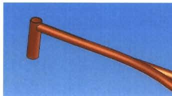
13 2.3 Material Selection There were four main materials identified that could be used for the frame: Titanium Steel Aluminum Carbon Performance Variables Weighting Factor Design Feature Tensile Strength Cost Manufacturability Durability Weight Total: Titanium Steel Aluminum Carbon Fiber Table 2 Based on the decision matrix, titanium and steel show the most promise. Titanium would be ideal for maximum performance but steel would be better for economic reasons. Since more emphasis had consistently been placed on enhancing performance, titanium was selected over steel. 2.4 Component Development Head Tube/Top Tube/Seat Stays The original top tube is a very simple part that took advantage of the simplicity of splitting the seat stays before the arc (shown in Appendix D, Figure A-l). While this design may have been easier to manufacture, it has several significant disadvantages. To start, the seat stays are very long, far longer than required by wheel clearance. Structurally, this is not ideal, nor is it ideal for the rider, who needs a narrow frame for knee clearance while riding. Second, this design is very heavy because for the majority of its length, the top tube is actually split into two tubes, giving it much more mass without any added benefits. This second design (shown in Appendix D, Figure A-2) discarded many of the disadvantages of the first phase discussed above. The top tube is much longer in this design, helping to create a much more efficient structure with respects to weight. It also has seat stays which taper more than previously, making the design more visibly appealing and also narrower for ease of riding. Wheel clearance continues to be overly conservative in this design as well. However, it is still not ideal in terms of overall weight. The third iteration of the design has the basic architecture as all the following design iterations. It has a longer top tube; the head tube is angled at 17 degrees, essential to proper mounting of the fork and front tire clearance with the rest of the frame. It also features a continuously variable curve in its seat stays, helping to maximize weight savings while still maintaining structural integrity. It also includes a cross bar, which could help in obtaining a mounting position for the seat tube, which was added in this phase of the frame design. 11


, with all of its dimensions fixed for the final design of the bike frame.")


14 Figure 7 The fourth design (shown in Appendix D, figure A-3) capitalizes on all the advantages of the third design phase and adds to them in order to create what is the final basic shape for the top tube. The major differences in this phase are the elongated top tube, which reduces weight, and also the much smoother transition into the seat stays, making the whole structure more of an arch shape. Wheel clearance was tested with this design and the split of the seat stays was made as gentle as possible while still providing good tire clearance. This model of the top tube is the final iteration (Figure 8), with all of its dimensions fixed for the final design of the bike frame. The only dimension not finalized is the tube thickness which can be adjusted in Algor during optimization. New features incorporated into this design include a tapered top tube, starting with a thicker cross section at the high stress area that attaches to the top tube. It then tapers down until it connects with the seat stays, which are also smaller than in previous iterations. The head tube has also been redesigned, with a thinner cross section in the middle and only widening out at the top and the bottom where the head set will be pressed into place. Figure Down Tube The down tube plays a major role in the front end stiffness of the frame. A frame that has a stiffer front end (i.e. head tube and surrounding area) responds faster to a rider's actions. Thus, a 12


15 better performing frame has a stiff head tube. To improve this, a diamond shaped down tube was chosen. This cross section better resists torsion than a normal circle. Additionally, a large height was chosen so thinner walls could be used. The initial wall thickness was 1.8mm, but this was later reduced due to FEA findings. Figure 9 shows a section view of the lower end of the down tube. Figure Seat Tube Initially, there was no seat tube in the design. During the continued discussions, it was decided that some kind of a seat tube or enclosed member would be beneficial. The main reason for this decision is rider control. The design team felt that without a tube holding the middle of the frame together, the response of the frame during an upward pull would be slow. However, to allow for free flex from the seatstays, a large forward angle was given. This allowed for longer seatstays and gave the frame an aggressive look. Another change from standard seat tubes was the dual tube concept used. Because of the long length, a single tube would have allowed for more torsional rotation in the middle of the frame. This was reduced by using a seat tube that attached to both edges of the bottom bracket and attached together to the top tube (Figure 10). The two tube concept also allows for a smaller tube diameter without reducing the strength and stiffness of the frame as a whole. The original diameters used were 25mm but this was reduced to 15mm after analysis. 13


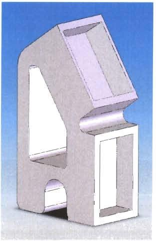
16 Figure Bottom Bracket Great attention was given to the bottom bracket area. The bottom bracket is the point that the pedal bearings are threaded into. As a result, the force from the pedals is applied directly to the area so the behavior of the bottom bracket affects the overall handling of the bike more than any other area. Care also had to be taken to ensure that the crankarms and chainrings will not interfere with the chainstay arms. Traditional bottom bracket shells are 68 or 72mm across. There are, however, bottom brackets for 100mm shells. This oversized shell width was chosen because it will provide the additional balance that is needed in trials riding. Additionally, an oversized shell diameter was also used to increase the torsional stiffness of the bottom bracket while allowing for a lower weight. An initial design (Figure A-6) was developed with rectangular sections of material removed from the top and bottom of the area directly behind the threaded area. Sections were also removed from the sides and bottom of the arms in an attempt to reduce weight while retaining stiffness from an I-beam type configuration. Following the assembly of the initial frame, time was spent analyzing the design in Algor to reduce weight without reducing stiffness. In addition to the rectangular cutout design, a bottom bracket was modeled that used triangular cutouts behind the threaded area (Figure 11). Both of these designs were analyzed with 17mm cutouts on the top and the bottom and with the cutouts going directly through the bottom bracket. The deflection in the x and y directions at the end of the arms were plotted vs. the weight of each configuration (Appendix B). Based on this plot, the triangular cutouts that go directly though had the lowest weight without giving up a great deal of lateral stiffness. Because the vertical deflection will be increased by the strain energy device, the stiffness in this direction was neglected. 14


17 Figure 11 Once the best concept had been chosen, additional analyses and changes were completed. The first major improvements came from moving the connection points of the angular ribs toward the center 5mm. Figure 12 shows a model with exaggerated displacement ofthe original rib configuration. The excess movement in the crossing rib can easily be seen near the corners. Figure 13 shows how much the movement was reduced by moving the ribs inward. Figure 12 Figure 13 Other large improvements included extending the bottom cutout to the outside triangle cutouts and adding one on the top surface to create a horizontal I-beam. This also greatly reduced displacement as well as the weight. The extensions of the triangle into the chainstays were also reduced and played a large role in this increase as well. Finally, increasing the radius of the transition from the bottom bracket to the chainstays from 10 to 15mm helped increase the stiffness and reduce the maximum stress seen from a lateral load (A complete chart of changes and deflections at each point can be found in the appendix). The final bottom bracket (Figure 14) has the same amount of deflection as the original concept but with a 32% reduction in volume. 15


18 Full frame analysis revealed a hot spot around the insert clamp area. To eliminate this, the thickness of the clap was increased. This did add a little weight but was necessary for the robustness of the design. Figure Strain Energy Component Several concepts for the specific design of the strain energy component were considered. The four concepts for analysis that were developed include: SPT flexboards turned 90 degrees in each chainstay box chainstays cut out and wrapped in carbon fiber chainstays with a thin cross section for flex Flat- diving board type - chainstays Based on the decision matrix (Table 2), it was determined that the composite insert would be the best solution for the strain energy component. Initially, an insert was designed that mirrored the one used by Slingshot Bicycle Company for their SPT. This new insert was needed because the width of the chainstays did not allow for the insert used for the SPT. Eventually, this was changed for the exact insert used in the SPT. This change was made to ease manufacturing difficulties. Because the SPT insert is 50mm across and the chainstays in the prototype design are 20-25mm, the insert was rotated 90 degrees. Performance Variables Weighting Factor Design Feature Spring Cost Manufacturability Durability Total Composite Insert Diving Board Carbon Wrap Thin Cross Section Table Chainstays Initial design of the chainstays, which connect the rear dropouts to the bottom bracket, consisted of bending a single rectangular bar. Slots would then be removed, cutting the piece threefold, for composite insert placement. Dog bone-shaped extrusions would be machined out in order to position and pin the flexible insert. The back side, or u-shaped piece, of the chainstays would 16


 made to the chainstays involved lightening holes extruded completely through the structure.")
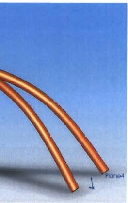
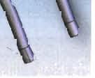
19 then be aligned and welded to the bottom bracket providing ample surface area. This concept proved to be quite heavy and perhaps over-engineered. The first improvement was to place the insert directly between the bottom bracket and the chainstays. This eliminated a weld and replaced it with the flex-feature while additionally dividing the chainstays into two separate and symmetrical parts. Another consideration coming into the picture was interference with the pedals. With the initial design, an essentially straight line was formed between the bottom bracket and the rear dropouts. This was not providing satisfactory pedal clearance. A bow, or kink, was included to keep the chainstays narrow as far aft as possible before mating with the dropouts. Additionally, the part was very heavy. Lightening holes were added which eliminated approximately half of the part's weight. Initial loading conditions were placed on the frame which returned minimal stress related consequences. The frame and its components were still rather weighty. The next modification (similar to Figure 15) made to the chainstays involved lightening holes extruded completely through the structure. Round holes were used in order to minimize localized stress concentrations and a bridge-like arrangement was formed. This configuration showed low stresses as well indicating excessive material. Also new for this revision was turning the composite insert on its side by 90 degrees. This would allow more flex throughout the frame and a different attachment mechanism (Figure 16). The chainstays also moved away from a solid structure and towards a hollow member. The solid housing for the composite insert is aligned and welded onto the hollow chainstays. ;.~' /' Q I J L^f /^ : -! /. Figure 15 Figure Dropouts The major constraints on the rear dropouts, which connect the chainstays, rear axle, and seatstays, are the angle and placement of the mating chainstays' and seatstays' surfaces. The initial design (shown in Appendix D, fig. A-5) contained deep wells for the chainstays and seatstays. The seatstays were initially rectangular and later changed to a circular cross section. After finding that the dropouts were a bit heavy and very strong, the next major change reduced the depth of these wells and attempted to consolidate the structure and overall size of the part. The rear axle was aligned with the center of the chainstays and the angle of the top surface was modified slightly to facilitate changes in the seatstays. 17


20 The final revision includes a number of changes while maintaining an appropriate amount of strength. The five to six millimeters width required for the rear axle clamp is included which allows 40% of the weight to be removed from the structure. Secondly, additional surface area is provided for the clamp on the rear axle. Third, the axle slot is positioned at a 15 degree angle to assist the clamp in reducing slippage of the wheel. Lastly, the rear wall of the structure is blended with a spline feature in order to avoid sharp stress concentrations. Figure 17 Figure Completed Frame Many attempts were made prior to completion of a satisfactory model. Complications with modeling software and assembly processes were core problems. To put the individual parts together, each one must meet the next exactly. If the distance was off by any number, however minute, the mate would not connect. To overcome this problem, specific meeting points needed to be defined so the different team members could model individually but still have the pieces fit together as if they were made as one. The first frame that incorporated all of the final design concepts is shown in Figure 19. Several problems in need of repair were instantly obvious. The first of these problems was the weight. This frame weighed 10.41bs which is more than two times the goal weight. This was the driving force behind the majority of the refinements at this stage. Another noticeable problem was the stand over height. The side view of the frame revealed that the top tube was much higher than desired. The measured stand over height was 382mm. This not only increased the weight, but a high top tube can impede performance in trials riding. When trying to move onto a high obstacle, the rider needs to be able to pull the bike as close to their body as possible to reach the extra height. Therefore, the top tube was lowered for future models. 18

 3. Design Analysis Figure 20 3.")

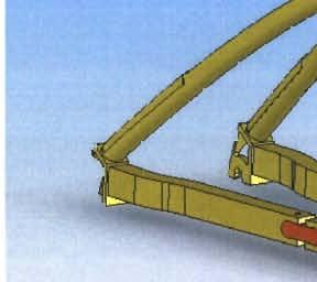
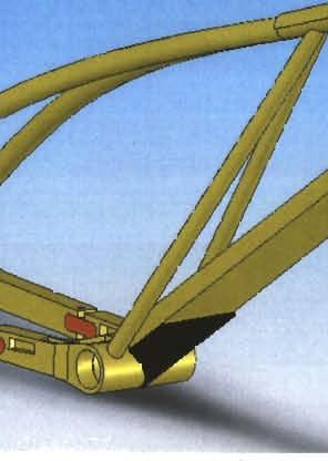
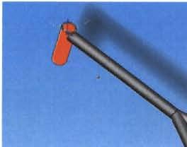
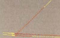
21 Figure 19 After making refinements to each part, a second complete model was assembled. This frame (Figure 20) had a much lower top tube and a reduced weight. The stand over height was now only 227mm. This is much lower than the target of 302mm. Additionally, the weight of the frame had been reduced to 5.41bs. This was still above the original target of 4.251bs but is within the range of competitive trials frames. Therefore, it was determined that this was an acceptable weight to begin finite element analysis. (For specific changes made to each component of the frame, see section 2.4) 3. Design Analysis Figure Qualitative Analysis Prior to complex modeling, a beam model of the selected concept was constructed. FEA was conducted on this model applying arbitrary loads to the rear wheel mounts. Arbitrary values were applied as this analysis was intended only to check that the behavior of the frame was the same as the solid composite rear suspension mechanism found during benchmarking. After analysis, the proposed trials frame concept was found to behave the same as the desired benchmark. When a vertical load (i.e. landing impact) was applied, the rear wheels moved upward and rearward (Figure 21- Yellow member). A horizontal load (i.e. drive chain tension) 19


22 moved the rear wheel down and forward (Figure 21- Red member). These results gave the design early verification that it could not only meet current benchmarks, but significantly improve the rider's performance as well. Figure Force Models Before detailed analysis of the frame could begin, knowledge was needed of the various loading conditions that will be seen during its lifetime. Initial attempts to gain load data were directed towards obtaining the actual force models used by the industry sponsor. Unfortunately, through discussions it was revealed that loads had not been previously acquired. Instead, the forces were determined through educated estimates using kinematics and energy methodology. To continue with the design process, the team investigated two possibilities of determining the loads experimentally. Eventually, various methods of mathematical calculations would be used to determine the expected loads a trials frame will be subjected to Load Cases The first loading case that needed to be analyzed is a 2-wheel landing. This is a common landing for trials riders when dropping the bike down from smaller heights. The exact maneuver to be analyzed is a drop from a height of four feet with the bike landing simultaneously on the front and rear wheels. The second loading case to be analyzed is a rear-wheel landing with the brake engaged. This is the most common type of landing the bike will experience. The advantage to the rider of landing on the rear wheel first is that the impact can be absorbed over a greater period of time by landing on the rear wheel first and then transferring to the front. This landing is necessary for drops of over five feet when the impact of landing on both wheels instantly would cause the rider to lose control. In the most extreme of cases, the bike and rider may be subjected to a fall of ten feet. This is height used for the analysis, and the load on the rear tire was estimated to be 70% of the total impact force. The rest of the impact force will be absorbed by the front tire once the rider transfers his or her weight forward. 20

23 3.2.2 Strain Gage Testing The next concept explored was affixing strain gages to an actual trials frame so as to measure strain across various frame members. Frame coatings, particularly paint, would need to be removed so the gages could be soldered directly to bare metal. The gages investigated were all composed of Wheatstone Bridge configurations. The most likely configuration to be used was the half or quarter bridge. Ten to fifteen foot wires attached to the bridge arrangement would lead to a signal conditioning device and then into a data acquisition system via National Instrument's LabVIEW, programmed on a portable laptop. Limited distance maneuvers in trials riding made this option of following the rider from obstacle to obstacle seemingly feasible. After further investigation, noise factors in long wires, the susceptibility of gages falling off, and the severe time constraints of the project made this option impractical. This strain gage method could have turned out to be a design project in itself Load Cell Testing Load cells commonly used in weighing vehicles surfaced as the next possibility for determining how much force is exerted on a frame during riding. If the bridge configuration inside the load cell was known, one could assemble a setup similar to that mentioned for the strain gages. To determine the loads, the rider would land on the scale and a peak value could be recorded. Another option was to remove the dampening component of a full suspension mountain bike. A smaller load cell could then be installed into the frame. The frame could then be ridden and the max force delivered to the rear wheel through that frame member could be determined. Unfortunately, these options failed because adequate information on the bridge setup inside of the load cell and a semi-destructible rear suspension bicycle frame were not available Mathematical Calculations Two mathematical approaches were used to approximate the forces seen by a trial frame. The first method used for force determination involved simple kinematics and energy equations. By choosing a height and rider weight, a model could be created to simulate impact mathematically. To compensate for the impact forces, observations were made about how much time it took for the rider to fully absorb the impact of a drop from the specified height. Assumptions Drop Height = 3 ft Tires Land Simultaneously Time Length of Impact =.2 sec Equations DQ0t] +(1/2)^ =cpj$ + (1/2)mV2 Acceleration = AW At Results Figure 22 V = 13.9ft/s F^2.16g's 21

24 Assumptions h1 = 3m h2 = Om At =.20sec Worst case ~ each tire 75% of load Tire Dampening - 10% Rider does not un-weight bicycle Equations UW i^^w IvW l^fcw a = (Vi - VJ)/(ti - tf) Results a = -2.93g F = mr+ba Figure 23 The second method of mathematical calculations involved the use of FEA software. In this method the bike frame was given boundary conditions according to each maneuver and subjected to a static force of the rider's weight. Analysis was run and the maximum displacement was recorded. Once the maximum static displacement was known, it was put into the following equation: Fe = W(l+V(l+2h/5st)) Fe W H 8st Where: = Equivalent Force = Weight = Initial Height = Static Displacement The static force is then replaced by the equivalent force, and using the same constraints, the model is analyzed again, this time for the impact loading. This developed loads of 155.4g and 87. lg for the 2-wheel and rear-wheel landings respectively. It is worth noting that both of these methods have inherent flaws which make them only approximations, as the difference in loading calculations suggests. The first method is very simple and can give only an idea of the load, and is also based on measurements of the time it takes for the rider to absorb a shock, which are subject to human error. It also does not take into account the flexibility of the frame, which is a significant factor in the magnitude of the impact force. The second method is excellent for getting an impact force for a specific frame configuration. However, this method neglects several crucial factors that affect the impact forces. The most important factor not included is the rider and tires absorbing some of the shock, essentially dissipating the load over time. This results in the equivalent force being abnormally large. Because of this, the second method has an inherent safety factor built in. It is extremely difficult to define exactly how much safety factor without some kind of empirical data reference. 22
25 3.2.5 Applied Loads Because of the large differences in the two mathematical approaches taken, more information was needed before the final loads were acceptably defined. Research was done on how many G forces an average human can withstand over a given period of time. This was important as it enabled the load to be limited to a force that the rider could take without falling off the bike or becoming severely injured. In essence, this study provided a ceiling of load values and was closely related to the loads used during the FEA. 200 JURATION s«c«mds Figure 24 1 H5 0 With this information, a compromise of the two methods was reached. The average impact time for a trials landing was estimated at 0.2 seconds. Based on the human acceleration data, the maximum load a human can tolerate for this time without sustaining injuries is around 20g. To build a safety factor into the analysis, this load was increased to 35g. This load was used for both the 2-wheel and rear-wheel landing. 3.3 Finite Element Analysis Once a frame was developed which was satisfactory in terms of weight, FEA analysis was begun to determine whether the frame would be able to withstand the loads encountered during use, both in a single instance and over time. As mentioned before, the two maneuvers the frame was designed to withstand are the 2-wheel landing and the rear-wheel landing. The design team chose the Solidworks Computer Aided Design (CAD) package for their solid modeling due to its user-friendly nature and its compatibility with ProEngineer's Mechanica. Of any FEA software packages that were available, the team seemed to have the most experience with Mechanica. Mechanica is a P-method solver which offers various thermal and structural analyses. This provides the advantage that the program automatically optimizes the needed functions to converge to the best solution. However, the method Mechanica uses to run the analyses requires extensive active memory and an hour would commonly be necessary to complete a study. Because of these problems, alternative software which could deliver results in 23


26 a timely and efficient manner was investigated. Algor simulation software was found to support Solidworks drawings and did not require extensive active memory to finish the analysis. However, this is a H-method solver so the element mesh needed to be refined by hand to converge to the best solution. While Algor's FEA solver introduced challenges of its own, it proved to be much more appropriate for the team's intentions Two Wheel Landing The two wheel landing is only used by a trials rider on relatively small drops or possibly in error. The highest drop a rider usually encounters when using a two wheel landing is four feet. This is the height that was used to determine the impact loading which is delved into more detail above. Once the bike frame was imported into Algor from SolidWorks it had to be constrained according to the force and boundary conditions that it would encounter in a real landing. The bottom of the head tube is pinned, which means that it will have zero displacement in the x, y, and z directions, although it is allowed to rotate freely about all axes. The rear dropouts are constrained in a similar manner. The boundary condition was applied to the surface which would contact the rear axle. It is pinned as well, to provide rotation about all axes, yet no translational motion. The force is applied downward on the bottom bracket. It is applied on the bottom inner surface of the tube where the pedal axle would sit. This simulates the rider's weight acting through the pedals upon landing (Figure 25). Based on the load cases calculated in the previous section and an approximately 2151b rider weight, the final force applied comes to N. For material constraints, all parts with the exception of the composite inserts are Titanium Alloy (6AI-4V). The composite inserts, are fiberglass bars. (For a table of material properties, see Appendix F) Figure 25 Some optimization was then completed using the two wheel landing maneuver with the following values for tube thicknesses: Top Tube Diameter: 1.7mm Down Tube Diameter: 1mm Head Tube Diameter: 2mm Seat Tube Diameter:.5mm 24


27 .: Load Ca: Maximum Value: Minimum Value Load Ca Maximum Value mm Minimum Value. 0 mm The results were in close proximity to those desired, and the weight was also within the target range. Several more iterations were run until this particular design was optimized to have the following tube thicknesses: Top Tube Diameter: 1.2mm Down Tube Diameter: 1mm Head Tube Diameter: 2mm Seat Tube Diameter:,5mm ;.. I *. * J Load Case. 1 of 1 Maximum Value Minimum Value Load Case 1 of t Maximum Value mm Minimum Value 0 mm From the analyses, we can see that the safety factor is close to one, which is sufficientto conclude that the frame will not break when this load case is applied. This is an acceptable level due to the conservative nature of the impact force calculations. Additionally, it is known that the material strength increases as loading rate increases, minding that the above safety factor is with respect to sustained loading. Following the rear wheel landing analysis for this same frame, it was determined that several reinforcements were necessary in order to make the bike frame safe Rear-Wheel Landing The rear wheel landing is the most rigorous load case that the frame was designed to withstand. This is probably the most commonly used landing by the trials rider, and is employed for the 25
.")


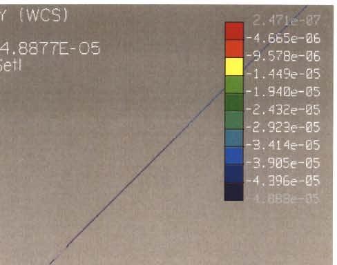
28 entire spectrum of drops between two feet to ten feet. For this analysis, the bike frame is only being analyzed for failure after the initial rear wheel impact. The bottom of the head tube is pinned where the front fork connects. The bottom bracket is also pinned, allowing rotation about all three axes with no translational motion (Figure 26). Finally, the impact force is applied to the point on the rear dropouts where the axles contact. Additionally, the load was applied at a fifty degree angle to the vertical because the rider always comes down on an angle when landingon the rear wheel. Upon inspection of initial rear-wheel analyses, it was discovered that the rear dropouts were moving horizontally away from the center line of the bike. This will not happen in actuality because the hub and axle of the rear wheel keep the dropouts the specified 135mm apart. To remove this unnatural movement, constraints against translation in the x direction were placed on the inside faces of both rear dropouts. As with the 2-wheel landing, the impact force was 35g for a rider of approximately 215 lb, resulting in an impact force of N. Figure 26 While the two wheel landing was already within the tolerances desired, the frame is sub par when subjected to the rear wheel landing. The minimum safety factor is typically between.2 and.3 which is unacceptable even with the highly conservative impact force, and it could not be said with confidence that the frame would remain intact over time. Results from the original frame are as follows: Top Tube Diameter: 1.7mm Down Tube Diameter: 1mm Head Tube Diameter: 2mm Seat Tube Diameter:.5mm 26


29 Fjetoi of Saf«t r Load Case: 1 of 1 Maximum Value: Y -4, Minimum Value: Top Tube Diameter: 1.2mm Down Tube Diameter: 1mm Head Tube Diameter: 2mm Seat Tube Diameter:.5mm After the stress analysis, it was determined that because the points on the frame of high stress were more or less concentrated to a couple spots. The best way to fix these problems while still keeping weight low was to add reinforcements to the affected areas. This adds a minimum amount of weight, and it is also simple to do and requires a minimum amount of time for manufacture. Figure 27 shows the reinforcements circled in red. Figure 27 The downside to adding reinforcement patches is that stress concentrations were produced at gusset-edges. However, FEA analysis showed that the concentrated stress was still less than it had been without the reinforcements and furthermore affected a much smaller area. Because the two wheel landing had already met the specifications desired in terms of safety factor, it was 27


30 unnecessary to re-analyze for this maneuver when adding additional material would only make the safety factor increase Final Optimization Once the reinforcements were added, the safety factor exceeded the intended goals for much of the frame. Once this was attained, it was then possible to reduce some weight by making tube thicknesses smaller. After much experimentation it was found that most of the tube thicknesses could be reduced without much consequence on the overall stress in the frame. After the final optimization, the tube thicknesses on the final frame design are as follows: Seat Tube =.5 mm Down Tube = 1.0 mm Down Tube Gussets =.75 mm Seat Stay Reinforcement =.75 mm Top Tube Reinforcement = 1.5 mm Top Tube =1.2 mm i Load Case: i of 1 Maximum Value Figure 28 Figure 28 shows the 2 wheel landing following the addition of reinforcements and subsequent optimization and weight reduction. It can be seen that the frame has a safety factor of greater than one everywhere except the bottom of the head tube. This however is a product of the boundary condition at this location and does not represent the real world stress that would be seen. This area needed to be constrained for no translational movement because allowing it to move in any direction would cause the model to pinwheel, making analysis impossible. In reality this area may move slightly as the front fork increases in angle to accommodate the lengthening of the wheelbase. In this condition there would not be the extreme bending stress that is present in the diagram. 28


 and it can be confidently said that the frame will not fail")


31 Load Case' 1 of :4^*x Maximum Value: Figure 29 Figure 29 shows the results of an analysis of the final frame during the rear wheel landing maneuver. This maneuver was more affected by the reinforcements than the two wheel landing, and the stress concentrations are noticeably different. Instead of totally eradicating the stress concentrations as happened in the two wheel landing, the reinforcements instead spread the stress out while at the same time reducing it. The safety factor is consistently greater than one, however, even in the areas of high stress above the seat tube and on the rear dropouts. While it is possible that there may be some minor yielding at these points, that does not equate to failure (noticeable deformation) and it can be confidently said that the frame will not fail under this load condition. This is due to the large safety factors already built into the impact loading and the increase in material strength during an impact load Fatigue Bike frames are also subjected to fatigue loading. The pedaling action from the rider provides the majority of this stress. To evaluate this phenomenon, an analysis was run using the same boundary conditions as the 2-wheel landing load case. However, instead of the 35g load spread over both sides of the bottom bracket, a 3g load was applied to one side of the bottom bracket. This was because when the rider is pedaling, all of his force will be on just the forward pedal. The stress limit to survive 106 fatigue cycles 6/4 titanium is 520MPa (Figure 30). 29
 The results of this analysis (Figure 31) showed that the stress in the frame is much less than the limit for fatigue.")
 had a weight of 4.71bs. This was slightly above the target weight of 4.251bs.")
32 Enduranet (cy<i**j H«t*»i»it-t<n«ilc>«T fatigut (,S-V ) nine* im three learnt «lir«lh'b» in " 7 nil (hick. forerd and annealed IWAWV bar Figure 30 (Boyer) The results of this analysis (Figure 31) showed that the stress in the frame is much less than the limit for fatigue. There was a bit of stress concentration on the bottom of the head tube near the down tube, however this was due to boundary conditions as described in section Final Design Figure 31 The final design (Figure 32) had a weight of 4.71bs. This was slightly above the target weight of 4.251bs. However, it is still within the competitive range of weights discovered during the benchmarking process. As the previous section has shown, the frame has sufficient strength to withstand the high impact nature of trials riding. It also will absorb the fatigue stress applied by pedaling without failure through at least 106 cycles. The final stand over height is 227mm. This is much less than the 302mm set as the minimum target. Since all of these constraints have been met or exceeded, an acceptable frame has been designed. 30


33 Figure 32 31
34 Bibliography Anonymous A. Performance. The BowGo Project. Retrieved 2/11/07 at 9:29 from Anonymous B. Bike trials riding. Wikipedia. Retrieved 2/10/07 at 10:20 from Anon. How to: Pedal-up, sidehop, gap, up to front wheel, and wheelswap. Observed Trials. Retrieved 2/10/07 at 11:30 from Anonymous C. Planet-X Ali Bongo. Chain Reaction Cycles. Retrieved 2/11/07 at 9:00 from Anonymous D. SlingPower Technology. SlingShot Bikes. Retrieved 2/10/07 at 11:55pm from Anonymous E. Pogo stick. Wikipedia. Retrieved 2/9/07 at 10:20 from Anonymous F. Flybar. Wikipedia. Retrieved 2/9/07 at 10:25 from Anonymous G. Fiberglass Technical Data. Retrieved 4/6/07 at 1:00 from Boyer HE. Atlas of Fatigue Curves American Society of Metals Crawford, Harry. Survivable Impact Forces on Human Body Constrained by Full Body Harness. Sept Health and Safety Executive. 10 April 2007 < Kram, Rodger., Dawson, Terence. (1997) Energetics and Biomechanics of Locomotion by Red Kangaroos. University of California. 32

35 Appendix A- Bike Diagram Seat Stays \ Rear Drop Outs 1 Seat Tube < V 1 V Head Tube *,^V»*W1._ 1 / ^r7" "^v^, \A\ V> j A <^ /\ \\V i- ""A "\ >. 1$& 1 Nt> /'' _^-*- * /j _Jv*. V \ \ 1 Down Tube kxf? 7 S/; Chain Stays ^"i* 1 \V Bottom Bracket % ' - 7/ 33
36 Appendix B- Bottom Bracket Design Analysis Horizontal Stiffness Comparison Square Square Through «.Triangle Triangle Through Weight Vertical Stiffness Comparison E «.!" e Square Square Through ATriangle Triangle Through Weight 34
37 Revision Level Change Right X-Displacement Left X-Displacement Volume Initial e e mm height e e shorter side cutout e e mm back brace and cross ribbing 4 5mm back brace w/4mm cross ribbing 5 5mm back brace w/4mm cross ribbing but moved rear pt 5mm inward 6 New insert cutoutnew loading placement 7 Moved rib point to 10mm inward 8 Moved side cut outs back, extended bottom cut outs and added top cut out 9 Increased depth on top and bottom cut outs, moved outside corner pt of through back 10 Moved outside corner pt of through forward 11 Increased rib thickness to 5 mm 12 Decreased BB shell diameter to 43mm, reduced arm width to 20 mm, made end thickness 21mm e e e e e e e e e e e le e e e e e e e e
38 Chapter IV EQUIPMENT Appendix-C- UCI Regulations The bike in general A trials bike shall have two brakes in working order (front and rear wheels) The frame, the handlebars and the fork shall not be cracked Pedals and wheels shall not show too much play No pedal hooks or toe-straps shall be allowed Bikes shall not have any sharp edges that could cause injury Tyres may not be fitted with chains, ropes or other devices. 26" Bikes (Mountain bikes) Normal commercially available 26" wheel mountain bikes with a minimum of working 6 gears of different size shall be permitted, (text modified on ). TRIALS REGULATIONS E Only one rock-ring chain guard shall be authorized on the transmission side. No additional, lower chain guard may be fitted. Retrieved 4/7/07 at 4:30pm from 36


39 Appendix D- Component Pictures Figure A- 1 Figure A- 4 Figure A- 2 Figure A- 3 Figure A-6 37

40 Appendix E- Quantitative Functional FE Analysis Results Vertical Load Horizontal Load 38
STRESS ANALYSIS OF BICYCLE PADDLE AND OPTIMIZED BY FINITE ELEMENT METHOD. S. Abeygunasekara 1, T. M. M. Amarasekara 2
 - 96 - STRESS ANALYSIS OF BICYCLE PADDLE AND OPTIMIZED BY FINITE ELEMENT METHOD S. Abeygunasekara 1, T. M. M. Amarasekara 2 1 Faculty of Engineering & Technology, Colombo International Nautical Engineering
Second Generation Bicycle Charging Station. Engineering Analysis
 Second Generation Bicycle Charging Station By Jonathan Jerome, Michael Klinefelter, Connor Kroneberger, Kori Molever, and Robert Rosenberg Team 22B Engineering Analysis Document Submitted towards partial
DECREE TECH FEATURES FELT LONG, LOW, SLACK GEOMETRY
 TECH FEATURES FELT DECREE In October 2015, Felt Bicycles introduced an entirely new trail bike into its family: the Decree. Through many iterations of development and design, plus demanding testing and
From Constraints to Components at Marin Bicycles
 From Constraints to Components at Marin Bicycles A Case Study for The Mechanical Design Process Introduction This case study details the development of the Marin Mount Vision Pro mountain bicycle rear
Finite Element Analysis of an Aluminium Bike Frame
 Finite Element Analysis of an Aluminium Bike Frame Word Count: 1484 1 1. Introduction Each new bike model must pass a series of structural tests before being released for public retail. The purpose of
Revisions to the Regulations for Agility Trials
 Revisions to the Regulations for Agility Trials Effective January 2, 2018 Equipment changes may be done prior to January 2, 2018, but must be completed by January 2, 2018 This insert is issued as a supplement
Design and manufacturing basalt and carbon fiber road bike frame.
 MATERIALES COMPUESTOS 15 1 Design and manufacturing basalt and carbon road bike frame. E. Romero, RACORMANCE Composites Bikes. J. Justo, F. París Group of Elasticity and Strength of Materials, University
INSTRUCTION GUIDE TRANSITION CARBON (ALL MODELS)
") INSTRUCTION GUIDE TRANSITION CARBON (ALL MODELS) THIS INSTRUCTION GUIDE CONTAINS IMPORTANT INFORMATION. PLEASE READ CAREFULLY AND STORE IN A SAFE PLACE. Congratulations! The Specialized bicycle you have
INSTRUCTION GUIDE TRANSITION CARBON (ALL MODELS) THIS INSTRUCTION GUIDE CONTAINS IMPORTANT INFORMATION. PLEASE READ CAREFULLY AND STORE IN A SAFE PLACE. Congratulations! The Specialized bicycle you have
FEA case Study: Rubber expansion joint for piping systems
 FEA case Study: Rubber expansion joint for piping systems Introduction The FEA Toolbox of Taniq makes it possible to simulate the behavior of a pipe expansion joint accurately under several load cases.
FREQUENTLY ASKED QUESTIONS ANSWERED! MOUNTING TO MY BIKE
 FREQUENTLY ASKED QUESTIONS ANSWERED! MOUNTING TO MY BIKE Will a Rohloff hub work on my bike? It is likely that the Rohloff hub will work on your bike as there are number of different hub configurations,
Spinner Bike Description
 Spinner Bike Description The Background A Spinner Bike is a piece of exercise equipment that allows its rider to mimic the muscular movements and to receive the physiological benefits of riding a bike
Analysis of Shear Lag in Steel Angle Connectors
 University of New Hampshire University of New Hampshire Scholars' Repository Honors Theses and Capstones Student Scholarship Spring 2013 Analysis of Shear Lag in Steel Angle Connectors Benjamin Sawyer
FRAMES, SUSPENSION, FORKS AND SHOCKS
 FRAMES, SUSPENSION, FORKS AND SHOCKS FRAMES.5 Frame, Suspension and Handling Cradle Frame Backbone Frame Diamond Frame Twin-Spar Frame Trellis Frame Frame Electrical Grounds FRONT SUSPENSION...12 Telescopic
Morgan DeLuca 11/2/2012
 Morgan DeLuca 11/2/2012 Telescoping Bicycle Rack for Transit Buses MSDI: TBD Project Description: The goal of this project is to modify the current transit racks to allow for additional bicycles. This
INTRODUCTION TABLE OF CONTENTS
 2 INTRODUCTION Thank you for choosing Servometer to design and manufacture your unique, new electrodeposited bellows for your particular application. The definitions, formulas and design parameters inside
NINER BIKES 2010 >> THE NEW JET 9. What makes the next-generation Jet 9 so much stronger and stiffer?
 1 THE NEW JET 9 What makes the next-generation Jet 9 so much stronger and stiffer? The evolution of the Jet 9 began with FEA (computer modeling) and real-world testing completed during the development
Quickie Rigid Series QUICKIE RIGID STYLE DURABILITY INNOVATION TECHNOLOGY ADJUSTABILITY OPTIONS LIFESTYLE
 Quickie Rigid Series STYLE DURABILITY INNOVATION TECHNOLOGY ADJUSTABILITY OPTIONS LIFESTYLE QUICKIE RIGID Ti Titanium Quickie T he Quickie Ti Titanium, the chair that expresses the essence of Quickie quick
NINER. RKT 9 RDO Big wheels and big ambitions Niner has created a community of cyclists who are BIKE TEST / NINER RKT 9 RDO. 46
 NINER RKT 9 RDO Big wheels and big ambitions Niner has created a community of cyclists who are fiercely loyal to its brand and for good reason. They have grown from a niche company into a strong contender
Stress evaluation of a bicycle crank arm connection using BEM
 Stress evaluation of a bicycle crank arm connection using BEM C. J. Hoff, R. E. Dippery & 3. Knapp Department of Mechanical Engineering Kettering University, USA Abstract An interesting problem encountered
Millennial Walker A multi-functional, elderly assistance walker with improved posture, comfort, and folding capabilities.
 Millennial Walker A multi-functional, elderly assistance walker with improved posture, comfort, and folding capabilities. Background & Research Question There are many different styles and categories when
E-trike Li Assembly Guide
 PREPARATION 1. Read this assembly manual BEFORE commencing assembly. 2. Carefully remove all the components and packaged hardware from the shipping boxes. 3. Unpack the contents of the large double box
Modeling of Hydraulic Hose Paths
 Mechanical Engineering Conference Presentations, Papers, and Proceedings Mechanical Engineering 9-2002 Modeling of Hydraulic Hose Paths Kurt A. Chipperfield Iowa State University Judy M. Vance Iowa State
Create a road in your house
 2016.5.20 All cyclists should be able to enjoy sport cycling without regard for the place or time. We want cyclists to be able to ride as hard as they want indoors regardless of the weather or time of
CHAPTER IV FINITE ELEMENT ANALYSIS OF THE KNEE JOINT WITHOUT A MEDICAL IMPLANT
 39 CHAPTER IV FINITE ELEMENT ANALYSIS OF THE KNEE JOINT WITHOUT A MEDICAL IMPLANT 4.1 Modeling in Biomechanics The human body, apart of all its other functions is a mechanical mechanism and a structure,
DX2/DXX Operating Instructions
 CHECK LINE BY ELECTROMATIC DX2/DXX Operating Instructions CHECK LINE INSTRUMENTS ELECTROMATIC E Q U I P M E N T C O., I N C. 600 Oakland Ave., Cedarhurst, NY 11516 U.S.A. TEL: 516-295-4300 FAX: 516-295-4399
owner s manual 2012 yeti arc
 owner s manual 2012 yeti arc YETI CYCLES 600 Corporate Circle, Unit D Golden, CO 80401 888.576.9384 www.yeticycles.com Table of Contents Brand Overview 06 Frame Features 08 Geometery 10 Maintenance Schedule
Design Methodology to Fabricate Foldable Bicycle
 Design Methodology to Fabricate Foldable Bicycle Prof. Mayur Shelke 1, Abhinav Tingne 2, Sajal Chandrakar 3, Prathamesh Bharti 4, Vishal Meshram 5, Tejas Dahikar 6 1, 2, 3, 4, 5, 6 (Department of Mechanical
Materials Selection and Design. Kene Mbanisi and Wole Soboyejo Worcester Polytechnic Institute Worcester, MA 01609
 Materials Selection and Design Kene Mbanisi and Wole Soboyejo Worcester Polytechnic Institute Worcester, MA 01609 From the Need Statement to Product Specifications First step in design is to formulate
TIMEMACHINE DISC. Stay Ahead of Time
 Stay Ahead of Time Stay Ahead of Time The new Timemachine Disc is the ultimate triathlon machine, the most refined expression of pure aerodynamic performance featuring cutting-edge disc brake technology.
Using Your Bike Friday : Folding Rear Rack
 Using Your Bike Friday : Folding Rear Rack Green Gear Cycling, Inc. 3364 W. 11th Ave. Eugene, OR 97402 800-777-0258 USA & Canada +1-541-687-0487 Int l +1-541-687-0403 Fax www.bikefriday.com info@bikefriday.com
comfort without compromising on performance and to fit your various needs on touring,
 Congratulations on your purchase of Goal-26X. Goal-26X is made to enhance comfort without compromising on performance and to fit your various needs on touring, shopping and communicating. Let s have fun
SUPERIOR TEAM/XP CRB BF-M03 SERVICE MANUAL
 SUPERIOR TEAM/XP CRB BF-M03 SERVICE MANUAL Superior would like to congratulate you on the purchase of your new bicycle. We place a great emphasis on the choice of materials and their processing so as to
Made in the USA. For Fall Protection Only. SafeLok Part Description
 Operations and Instruction Manual SafeLok Anchorage - Model # 4011 IM-0051 REV A Portable Concrete and Steel Anchorage Connector ANSI Z359.1-07 5,000 lbs / 22kn Made in the USA The 3/4 Fall Protection
EZ-3 USX HD Supplemental Owner s Manual
 EZ-3 USX HD Supplemental Owner s Manual Find us online at SunSeeker.Bike Revised 2/2016 CONGRATULATIONS! Congratulations and welcome to the Sun Seeker family! You have selected one of the most comfortable
Special instruction of installation for SAINT FH-M800/RD-M800 and FH-M805/RD-M805
 Technical Service Instructions SI-5VB0E t RD-M805 / RD-M800 Rear derailleur Special instruction of installation for SAINT FH-M800/RD-M800 and FH-M805/RD-M805 A hub axle is an essential component for the
Sprocket Selection Guidelines
 Sprocket Selection Guidelines Table 1 Information Necessary to Order Sprockets 1. Chain Size Number, type, or drawing number of the chain to be used on the sprocket. (The suitability of a sprocket depends
This document is a preview generated by EVS
 INTERNATIONAL STANDARD ISO 4210-2 Second edition 2015-09-01 Cycles Safety requirements for bicycles Part 2: Requirements for city and trekking, young adult, mountain and racing bicycles Cycles Exigences
WHITE PAPER Copyright Cicli Pinarello SRL - C.F. e P.I
 WHITE PAPER 2017 - Copyright Cicli Pinarello SRL - C.F. e P.I. 05994100963 INDEX 0. INTRODUCTION... 3 1. PINARELLO NYTRO BIKE CONCEPT... a. PURPOSES OF THE PROJECT... b. HANDLING AND RIDING FEELING...
NOT ALL CARBON IS CREATED EQUAL
 NOT ALL CARBON IS CREATED EQUAL 3K WEAVE 1K WEAVE Uni Direction Pre-Preg Trigon has been a manufacturer of carbon products for the last 25 years. However, the owners and workers have near 30 years of experience
Ultra Lightweight Family
 Ultra Lightweight Family Live without limits Living an active life means putting your heart and soul into it, being part of something, taking a deep breath of nature, freeing your mind, and going beyond
DESIGN OPTIMIZATION OF WORK ROLL CHOCK AND BACKUP ROLL CHOCK IN COLD ROLLING MILL
 DESIGN OPTIMIZATION OF WORK ROLL CHOCK AND BACKUP ROLL CHOCK IN COLD ROLLING MILL Tukesh Sahu 1, Prof. G.R.Kesheory 2 1M.Tech Scholar, Department of Mechanical Engineering, VITS Indore, MP, India 2Assistant
Applications of trigonometry
 Applications of trigonometry This worksheet and all related files are licensed under the Creative Commons Attribution License, version 1.0. To view a copy of this license, visit http://creativecommons.org/licenses/by/1.0/,
ELECTRON PRO 245A: ASSEMBLY GUIDE. Revision Valid for MY2017 Electron Pro
 ELECTRON PRO 245A: ASSEMBLY GUIDE Revision 2.0 04-19-2017 Valid for MY2017 Electron Pro ELECTRON PRO 245A: Table of Contents 1. Tools Needed and First Aid Kit...3 2. Specifications...4 3. Configurations...5
Trilogy Theory of Operation
 INSTALLATION & OVERVIEW... 2 Load Height... 2 Approach Angle... 2 Footprint... 3 Protrusion... 3 Mounting the... 4 General Torque Specs... 4 OPERATION OF BIKE RACK... 5 Loading Bikes... 5 Unloading Bikes...
600 Corporate Circle, Unit D Golden, CO USA P// //
 Yeti Cycles 600 Corporate Circle, Unit D Golden, CO USA P//303.278.6909 // 888.576.9384 www.yeticycles.com A R C - X O W N E R S M A N U A L 0 8-1 0 Table of Contents Brand Overview 6 Frame Features 8
Lectric Cycles Mid-Drive Electric Motor Installation
 Lectric Cycles Mid-Drive Electric Motor Installation This write-up describes the installation of a Lectric Cycles electric motor. The model is the e-rad Mid-Drive 750 Watt conversion kit, installed on
INSTRUCTION MANUAL. January 23, 2003, Revision 0
 INSTRUCTION MANUAL Model 810A In-Vitro Test Apparatus for 310B Muscle Lever January 23, 2003, Revision 0 Copyright 2003 Aurora Scientific Inc. Aurora Scientific Inc. 360 Industrial Parkway S., Unit 4 Aurora,
Biomechanics of Parkour: The Vertical Wall-Run Technique
 University of Colorado, Boulder CU Scholar Undergraduate Honors Theses Honors Program Spring 2015 Biomechanics of Parkour: The Vertical Wall-Run Technique Integrative Physiology, Peter.Lawson@Colorado.EDU
STUDY OF UNDERWATER THRUSTER (UT) FRONT COVER OF MSI300 AUTONOMOUS UNDERWATER VEHICLE (AUV) USING FINITE ELEMENT ANALYSIS (FEA)
 FRONT COVER OF MSI300 AUTONOMOUS UNDERWATER VEHICLE (AUV) USING FINITE ELEMENT ANALYSIS (FEA)") STUDY OF UNDERWATER THRUSTER (UT) FRONT COVER OF MSI300 AUTONOMOUS UNDERWATER VEHICLE (AUV) USING FINITE ELEMENT ANALYSIS (FEA) M. Sabri 1, 2, T. Ahmad 1, M. F. M. A. Majid 1 and A. B. Muhamad Husaini
STUDY OF UNDERWATER THRUSTER (UT) FRONT COVER OF MSI300 AUTONOMOUS UNDERWATER VEHICLE (AUV) USING FINITE ELEMENT ANALYSIS (FEA) M. Sabri 1, 2, T. Ahmad 1, M. F. M. A. Majid 1 and A. B. Muhamad Husaini
SUPERIOR X-ROAD CRB BF-RB03/BF-F05 SERVICE MANUAL
 SUPERIOR X-ROAD CRB BF-RB03/BF-F05 SERVICE MANUAL Superior would like to congratulate you on the purchase of your new bicycle. We place a great emphasis on the choice of materials and their processing
ELECTRON PRO: ASSEMBLY GUIDE. Revision Valid for MY2017 Electron Pro
 ELECTRON PRO: ASSEMBLY GUIDE Revision 1.0 10-20-2016 Valid for MY2017 Electron Pro ELECTRON PRO: Table of Contents 1. Tools Needed and First Aid Kit...3 2. Specifications...4 3. Configurations...5 4. Geometry...7
Design Project 2 Sizing of a Bicycle Chain Ring Bolt Set ENGR 0135 Sangyeop Lee November 16, 2016 Jordan Gittleman Noah Sargent Seth Strayer Desmond
 1 Design Project 2 Sizing of a Bicycle Chain Ring Bolt Set ENGR 0135 Sangyeop Lee November 16, 2016 Jordan Gittleman Noah Sargent Seth Strayer Desmond Zheng 2 Abstract This report will analyze our calculations,
Good tread, no splits, cracks or holes, properly inflated. True, no missing or broken spokes, good rim. Secure, facing in right direction
 APPENDIX 1 Bike Check This is an M check. Start at the front of the bike and systematically work towards the back. Put a cross beside anything that is faulty. Note any faults you find. X FAULT Front tyre
IGNITE CARBON 29. frame passport
 IGNITE CARBON 29 frame passport last update: 11/10/2017 INDEX 0. UPDATES... 3 1. GENERAL... 3 1.1. Description... 3 1.2. Part codes... 3 2. MATERIAL... 3 3. WEIGHT... 3 3.1. Frame... 3 4. GEOMETRY... 4
Other Si min/max. Cr min/max. 0.4/ / / / Bal.
 178.46 Specification 3AL seamless aluminum cylinders. (a) Size and service pressure. A DOT 3AL cylinder is a seamless aluminum cylinder with a imum water capacity of 1000 pounds and minimum service pressure
6. EXPERIMENTAL METHOD. A primary result of the current research effort is the design of an experimental
 6. EXPERIMENTAL METHOD 6.1 Introduction A primary result of the current research effort is the design of an experimental setup that can simulate the interaction of a windmill with a vortex wake and record
INTRODUCTION TABLE OF CONTENTS 1. ENGLISH INTRODUCTION...PAGE 1 GEOMETRY / FRAME SPECIFICATIONS...PAGE 2-3 FRAME FEATURES...
 TABLE OF CONTENTS INTRODUCTION...PAGE GEOMETRY / FRAME SPECIFICATIONS...PAGE - FRAME FEATURES...PAGE -5 SEAT POST SET-UP...PAGE -5 FRAME HARDWARE KITS...PAGE 6-9 REPLACEABLE DERAILLEUR HANGER...PAGE 0-
Installation and Operation Instruction Manual
 Installation and Operation Instruction Manual Toggle Lok Anchor - Model #7442 Portable Concrete Anchorage Connector ANSI Z359.1 5,000 lbs / 22.24 kn FallTech, Inc 1306 Alameda Street Compton, CA 90221
Niner Introduces Full Carbon BSB 9 RDO Cyclocross Bike & Updated JET9 RDO w/ Limited Edition Build
 of 24 6/23/2014 12:55 PM Niner Introduces Full Carbon BSB 9 RDO Cyclocross Bike & Updated JET9 RDO w/ Limited Edition Build posted by Tyler Benedict - June 17, 2014-11am EDT It s been teased, and people
User Instructions 1789 Parapet Wall Anchor
 User Instructions 1789 Parapet Wall Anchor This manual is intended to meet the Manufacturer Instructions as required by ANSI Z359.1 and should be used as part of an employee training program as required
RELIABILITY ASSESSMENT, STATIC AND DYNAMIC RESPONSE OF TRANSMISSION LINE TOWER: A COMPARATIVE STUDY
 RELIABILITY ASSESSMENT, STATIC AND DYNAMIC RESPONSE OF TRANSMISSION LINE TOWER: A COMPARATIVE STUDY Yusuf Mansur Hashim M. Tech (Structural Engineering) Student, Sharda University, Greater Noida, (India)
2012 FELT F SERIES WHITE PAPER 1. INTRODUCTION 2. DESIGN PRINCIPLES 3. DEVELOPMENT 4. MATERIALS ENGINEERING 5. FEATURES AND SPECS
 2012 FELT F SERIES WHITE PAPER 1. INTRODUCTION 2. DESIGN PRINCIPLES 3. DEVELOPMENT 4. MATERIALS ENGINEERING 5. FEATURES AND SPECS INTRODUCTION Few, if any, competitive road bikes being raced today have
Ergonomic Downhill Series Developed with Fab Barel & Tahnée Seagrave. English Version
 All about control Ergonomic Downhill Series 2017 Developed with Fab Barel & Tahnée Seagrave English Version GD1 Factory The first MTB Gravity Grip with tapered grip shape (patent pend.). More damping in
CRUZBIKE Quest 2.0 Assembly
 CRUZBIKE Quest 2.0 Assembly CRUZBIKE Quest 2.0 Assembly... 1 General notes on assembly... 2 Un box and evaluate the frame and major parts... 2 Unfold the rear swing arm and arrange the frame... 3 Rear
Walking Simulator Mechanism
 The Downtown Review Volume 2 Issue 2 Article 4 2015 Walking Simulator Mechanism Titus Lungu Cleveland State University Igor Tachynskyy Cleveland State University Omri Tayyara Cleveland State University
FASTER FROM EVERY ANGLE. TEST RESULTS. The All-New Propel Advanced SL
 FASTER FROM EVERY ANGLE. The All-New 2 ENGINEERED TO BE THE WORLD S FASTEST AERO BIKE, THE ALL-NEW PROPEL ADVANCED SL FEATURES CUTTING-EDGE TECHNOLOGIES AND UNRIVALED CRAFTSMANSHIP. The frame s tube profiles
CONSTRUCTOPEDIA NXT Kit 9797
 CONSTRUCTOPEDIA NXT Kit 9797 Beta Version 2.0 August 17, 2007 Center for Engineering Educational Outreach Tufts University Table of Contents Simple Shapes and Structures. Page 3 Ways To Attach NXT Motors...
Tri-Better Detailed Design Review
 Tri-Better Detailed Design Review Designers: Michael Kurvach Nathaniel Morefield Ryan Wilson Cody Woods Guide: Dr. Richard Lux Project Overview The goal of this project is to create a shoe and pedal which
NEXT EXIT THE GREAT OUTDOORS POPULATION: EVERYONE
 2017 NEXT EXIT THE GREAT OUTDOORS POPULATION: EVERYONE SportRack is proud to offer safe, quality products that allow you to take full advantage of your vehicle s carrying capacity. SportRack accessories
helium SLA frame passport
 helium SLA frame passport type: 7E2 last update: 25/09/2017 INDEX 0. UPDATES... 3 1. GENERAL... 3 1.1. Description... 3 1.2. Part codes... 3 2. MATERIAL... 3 3. WEIGHT... 3 3.1. Frame... 3 3.2. Fork...
Materials Selection Lab Report
 Roman Kyrychenko Page 1 of 8 Student Number: 997484404 Lab Practical Section: 0104 Materials Selection Lab Report by Roman Kyrychenko Faculty of Applied Science and Engineering University of Toronto Unsupervised
Optimization of an off-road bicycle with four-bar linkage rear suspension
 Proceedings of MUSME 2008, the International Symposium on Multibody Systems and Mechatronics San Juan (Argentina), 8-12 April 2008 Paper n. 02-MUSME08 Optimization of an off-road bicycle with four-bar
Final Assembly Instructions Bikes with Quill Stems
 Final Assembly Instructions Bikes with Quill Stems Thank you for buying your new bicycle from L.L.Bean. Read these instructions carefully before beginning the final assembly. Prior to shipping, our expert
Final Assembly Instructions Bikes with Threaded Headsets
 Final Assembly Instructions Bikes with Threaded Headsets Thank you for buying your new bicycle from L.L.Bean. Read these instructions carefully before beginning the final assembly. Prior to shipping, our
Ultra Lightweight Family
 Ultra Lightweight Family Live without limits Living an active life means putting your heart and soul into it, being part of something, taking a deep breath of nature, freeing your mind, and going beyond
Ultra Lightweight Family
 Ultra Lightweight Family Live without limits You want cutting-edge wheelchair technology to keep pace with the demands of your active life. For over 30 years, Quickie has listened, researched, tested and
Protecting your punching tool investment. Application-related problems and solutions
 Protecting your punching tool investment Application-related problems and solutions Article reprinted with permission from the May 2000 issue of The FABRICATOR. By Nick Tarkany Economic shortcuts in the
MASTER TRUING STAND TS-3. Optional Dial indicator set with brackets Dial indicator bracket set only
 MASTER TRUING STAND TS-3 3 2 1 3 8 9 4 10 7 6 5 12 13 Optional 1555-1 Dial indicator set with brackets 1556-1 Dial indicator bracket set only 49 11 16 14 15 48 32 31 37 38 20 19 17 18 34 39 21 36 22 33
IJESRT INTERNATIONAL JOURNAL OF ENGINEERING SCIENCES & RESEARCH TECHNOLOGY DESIGN AND MATERIAL STUDY OF RACE BIKE CRANK PL. Vairakanna*, M.
 IJESRT INTERNATIONAL JOURNAL OF ENGINEERING SCIENCES & RESEARCH TECHNOLOGY DESIGN AND MATERIAL STUDY OF RACE BIKE CRANK PL. Vairakanna*, M. Chandran * PG Scholar, Department of Mechanical Engineering,
TABLE OF CONTENTS INTRODUCTION
 R3 DISC MANUAL TABLE OF CONTENTS Introduction... 1 Frame Features... 2 Fork Preparation... 3 Small Parts... 5 Frame Preparation... 6 Brake Housing Installation... 7 Mechanical Cable Routing... 9 Electric
HiPerMax LuK tooth chain for transmissions Reliable Power Flow in the Drive Train
 HiPerMax LuK tooth chain for transmissions Reliable Power Flow in the Drive Train Andreas Englisch Michael Pichura LuK SYMPOSIUM 2006 87 6 LuK tooth chain for transmissions Introduction A modern drive
Unit for Determining the Gauge Factor of Strain Gauges
 Engineering and Technical Teaching Equipment Unit for Determining the Gauge Factor of Strain Gauges MFGE PROCESS DIAGRAM AND UNIT ELEMENTS ALLOCATION ISO 9001: Quality Management (for Design, Manufacturing,
Chain induced stresses in recumbent bicycle frames. Stephen Nurse, January 11, 2018
 Chain induced stresses in recumbent bicycle frames. Stephen Nurse, January 11, 2018 ABSTRACT Recumbent bicycles can travel at higher speeds for the same effort and be more aerodynamic than standard safety
College of Engineering
 College of Engineering Department of Mechanical and Aerospace Engineering MAE-250, Section 001 Introduction to Aerospace Engineering Final Project Bottle Rocket Written By: Jesse Hansen Connor Petersen
BIKE CHAIN BASICS. Figure 1 - Two different sizes of bicycle chain
 BIKE CHAIN BASICS Figure 1 - Two different sizes of bicycle chain When creating your own human powered vehicles, a chain drive will likely be your chosen power transfer system, as it is an inexpensive,
REAL. Simple, Intuitive, Powerful Real.
 REAL Simple, Intuitive, Powerful Real. When we set out to define the bikefitting.com toolset engineered by Shimano Dynamics Lab, these were a few of the stand out priorities we wanted to achieve. We delivered.
Autodesk Moldflow Communicator Process settings
 Autodesk Moldflow Communicator 212 Process settings Revision 1, 3 March 211. Contents Chapter 1 Process settings....................................... 1 Profiles.................................................
Soling Building Tips II
 Soling Building Tips II Prepared: Arthur Deane Jan 20, 2002 adeane@ic.net Introduction The following are some lessons learned and experience gained in building a Soling kit. The plan developed is based
HELMETS SAVE LIVES!!! ALWAYS WEAR A PROPERLY FITTED HELMET WHEN YOU RIDE YOUR SCOOTER. DO NOT RIDE AT NIGHT. AVOID RIDING IN WET CONDITIONS.
 HELMETS SAVE CORRECT FITTING - MAKE SURE YOUR HELMET COVERS YOUR FOREHEAD. LIVES!!! ALWAYS WEAR A PROPERLY FITTED HELMET WHEN YOU RIDE YOUR SCOOTER. DO NOT RIDE AT NIGHT. AVOID RIDING IN WET CONDITIONS.
Parts List. 7. Handlebars 8. Grips 9. Handlebar Stem 10. Front Brake 11. Front Wheel 12. Crank 13. Chain
 Woodworm Cruise Parts List 1. Free Wheel with Rear Hub 2. Fenders 3. Fender Stay 4. Quick Release 5. Saddle 6. Seat Post 7. Handlebars 8. Grips 9. Handlebar Stem 10. Front Brake 11. Front Wheel 12. Crank
Sitting. Volleyball. Skills and Systems
 Sitting Volleyball Skills and Systems Sitting Volleyball Skills Ready Positions There are two ready positions commonly used in sitting volleyball depending on the situation presented. Reception ready position
Taiwan Bicycle Industry Standard
 Taiwan Bicycle Industry Standard TBIS 4210-9 First edition 2016.01.01 Cycles Safety requirements for bicycles Part 9: Saddles and seat post test methods Reference number: TBIS 4210-9:2015 (FDTS) Contents
ASME Boiler & Pressure Vessel Code Analysis of the 1497 MHz High-Current Cryomodule Helium Vessel
 1.0 Introduction ASME Boiler & Pressure Vessel Code Analysis of the 1497 MHz High-Current Cryomodule Helium Vessel Katherine Wilson 28 May 2007 To minimize the hazards associated with vacuum and pressure
Mining scalers are used in. Designing a stable suspension. F l u i d P o w e r. Demanding application requires unique engineering approach.
 Designing a stable suspension Demanding application requires unique engineering approach. by John H. Haselow BTI s QS45 Series Scalers use a vibratory scaling head that combines the action of a pry-bar,
APPLICATION OF PUSHOVER ANALYSIS ON EARTHQUAKE RESPONSE PREDICATION OF COMPLEX LARGE-SPAN STEEL STRUCTURES
 APPLICATION OF PUSHOVER ANALYSIS ON EARTHQUAKE RESPONSE PREDICATION OF COMPLEX LARGE-SPAN STEEL STRUCTURES J.R. Qian 1 W.J. Zhang 2 and X.D. Ji 3 1 Professor, 3 Postgraduate Student, Key Laboratory for
Transcript of Ping Pong Ball Launcher Research and Design
 Transcript of Ping Pong Ball Launcher Research and Design Objective To construct a mechanism to launch a ping pong ball into a garbage bin 2, 4, 6, and 8 metres away from the launcher, with restrictions:
Top End Recreation Handcycle Series
 Top End Recreation Handcycle Series Top End Excelerator Handcycle If you want a great way to exercise, cross-train or just have fun, the Top End Excelerator handcycle is what you need. This upright and
OTSO VOYTEK. Otso Cycles is a new bicycle company from the engineers. Designed to excel in any condition BIKE TEST / OTSO VOYTEK
 BIKE TEST / Designed to excel in any condition Otso Cycles is a new bicycle company from the engineers at Wolf Tooth Components. One might ask where they got this unique name, and the founders are happy
First Look: Cannondale Habit. By: Bike Mag Published: August 4, 2015
 First Look: Cannondale Habit By: Bike Mag Published: August 4, 2015 The details are out on Cannondale s new trail machine after a couple months of photos and speculation floating around on the internet.
SCOTT SPORTS SA _17 RTE DU CROCHET_1762 GIVISIEZ_SWITZERLAND _ 2009 SCOTT SPORTS SA, ALL RIGHTS RESERVED_SCOTT-SPORTS.
 SCOTT SPORTS SA _17 RTE DU CROCHET_1762 GIVISIEZ_SWITZERLAND _ 2009 SCOTT SPORTS SA, ALL RIGHTS RESERVED_SCOTT-SPORTS.COM V GAMBLER CONTENT The Gambler should be adjusted exactly to the current rider for