- Single Seat Sport Sailplane - C 30 EDELWEISS
|
|
|
- Agatha Jenkins
- 5 years ago
- Views:
Transcription
1 FLIGHTANDOPERATIONALMANUAL For - Single Seat Sport Sailplane - C 30 EDELWEISS Serial Number : 11 Registration: 4X-GJA Certified by Republic of France General Secretariat of Civil Aviation Edition i
2 Certified by Republic of France General Secretariat of Civil Aviation Flight and Operation Manual For Sailplane type: C.30.s EDELWEISS Edition Authorized Manufacture: SIREN 13, rue Saint-Honore - VERSAILLES plant ARGENTON-sur-CREUSE (Indre) It belongs to the sailplane C.30.s Edelweiss Serial number : 11 Registration number: 4X-GJA This manual should be always carried in the sailplane This manual is translation of the French original. The certification and limitations as approved by the Republic of France General Secretariat of Civil Aviation, are based on Air 2045 regulations of 27/10/1964 for category II. In any case, original text in French language is authoritative. ii
3 No. Description Page Date Signature 1 Emergency procedures 17 1/5/2012 AmendmentstoManual iii
4 Table Of Content Chapter I Description Page 1- General 1 2- Wing 2 a) Structure b) Moving elements 3- Fuselage 2 4- Tail 3 5- Landing Gear 3 6- Controls 3 a) Flight controls b) Utility controls 7- Accommodation 5 Chapter II Limitations 1- Speed Limits (Air Speeds) 6 2- Load Factor limits 6 3- Weight and Balance 6 4- Equipment 7 5- Aerobatic Maneuvers 7 6- Airspeed Calibration 8 7- Limit Speeds Placard 8 8- Loading procedure 8 Chapter III Operation 1- Ground Operation 10 a) Assembly b) Disassembly c) Handling d) Pre flight inspection e) Check list before takeoff Flight Approach and Landing Emergency Procedures 17 iv
5 Chapter I Description 1. General The glider SIREN C.30 "EDELWEISS" is a single-seat competition sailplane, conforming to the requirements of the FAI standard class. It has a single, cantilever wing at medium height, with a pilot space in the internal duct. It has a V tail and a single fixed landing wheel. The glider can be equipped with an electric variometer, a radio and oxygen installation. Its general characteristics are as follows: Wings: Surface 12.5 m 2 Span 15 m Aspect Ratio 18 Dihedral 3º Taper ratio Sweep-back at leading 0 edge Profile NACA 64 (modified 7 series) Median line combination of 3 median lines Ailerons: Percentage of span 28.4% Constant relative cord 38% Type Embedded Movement Range Up = 26º Down = 17º Fuselage: Overall length m Frontal Cross section- Height: 0.700m Width: 0.600m Cross section area: 0.35 m2 90º V Tail: Total Surface: 2.20 m 2 (2 x 1.1 m 2 ) 1
6 Landing Gear: Main: Tail: Two positions exist: training and competition. Wheel size 330 x 130, hydraulic brake, actuated at the end of the airbrake handle travel. Spring skid. Weights Maximum Empty with standard equipment = 380 kg = 238 kg 2. Wings a) Structure The wing is of a single-spar type. The whole skin is made of a plywood laminate with central layer of Klégécell. It is manufactured in two parts, which are joined by glue. A main part which envelopes the whole undersurface, the leading edge and the upper surface up to the spar, and a secondary panel which ends the skin of the upper surface behind the spar. The spar is made just of a stiffened web, in plywood, closing off the leading edge box. The spar caps are made of spruce segments, where the main cap runs the whole span in the laminate which constitutes the skin, and the secondary caps ensures the progressive thickening of the cross-sections. The skin laminate consists of an exterior sheet of 12/10, an internal sheet of 8/10, laminated with grain opposed in 45º, and a web of Klégécell of 4mm thickness. 11 ribs in the leading edge, 12 in the aft part, give rigidity to the wing box. These are generally perpendicular to elements, which receive the concentrated forces, such as the ailerons bearing arms. b) Moving Elements The airbrake are cut-out panel type, which come out perpendicular to the profile, on the under side and the upper side; they are made on each side of two elements of corrugated sheet metal over which are mounted adjustable hats made of light alloy. Each element is mounted on two rocker arms, which can swing about their central axis, where the entire assembly forms an articulating quadrilateral, which displaces between two spars reinforced by the working skin. The ailerons occupy 20.4% of the wingspan. They have a constant relative cord and are embedded, un-slotted, with a cloth sealing between the upper surface and the lower surfaces. They are statically balanced at 20%. Two end skids form an integral part of the wing tips, protecting the wing and assuring ground clearance of the ailerons. 3. Fuselage Is made of: - a fiber-glass laminate nose cone. - a cockpit 2
7 - tail boom These latter two sub-assemblies are made of plywood laminate/klégécell with incorporated longerons. They are joined by glue. The tail cone made of laminate ends in a lifting handle. 4. Tail The tail is made of two all-moving symmetrical elements, which are made of laminate for the leading edge, with the aft part covered in cloth. Each one of them turns about an axis, can be detached for transportation on a trailer. The trim tabs, made of sheet metal, and whose purpose is to regulate the elevator forces, are adjustable in flight and also function as anti-servo tabs. 5. Landing Gears The main landing gear is of a single-wheel type. The Wassmer 330 x 130 wheel, is damped by bungee cords, and can be fixed according to choice in training position (normal clearance) or in competition position (minimum clearance) hydraulic braking. The bottom of the fuselage is protected in front of the wheel by a AU4G sheet pressed in a strip of Klégécell. The tail landing gear is made of a three-blade spring, freely pivoting 90º to each side. 6. Controls a) Flight controls These are of three types: rods, semi-rigid, and cables. The rudder control is made of an open circuit of two cables, supply a hook support on the front frame, and wrap around pedal pulleys, then pulleys located at the front of the bottom of the rod and finally drive a bell crank. The circuit is closed elastically by two bungee cords fixed respectively to each of the pedals. From this bell crank to the tail differential, the movement is transmitted by a semi-rigid control. Control Column of classic form, the moving assembly is made of AU4G sheet, folded and riveted. The Elevator control is rigid between the control column and the bell crank located in front of it. The elevator bell crank and the rudder bell crank have the same rotation axel. From the bell crank to the tail differential, the movement is transmitted by a semi-rigid command. A common assembly for the rudder and elevator controls can be found between the differential and the tail. This assembly is made of a cardan, of which the exterior crown is driven by the semi-rigid controls. The movement of the cardan is transmitted to the bell cranks through right and left rods. Each of these moves a pin of the tail surfaces. Trim Control is achieved by a lever on the left side. A semi-rigid control attached to the lever drives a bell crank situated in front of the cardan. The movement is transmitted to the bell cranks through two small rods. These carry the positioning pins, which control the movement of the trim tabs. 3
8 Roll Control connected to the foot of the control column, two cables are guided by pulleys, hug the sides of the fuselage and drive the two bell cranks in front of the central mechanism. These bell cranks have l Hotellier attachment points, enabling connection of the wing rods. In the wings, the controls are rigid. After the wing root rod a second rod drives the differential bell crank, whose movement is transmitted to the aileron through a small rod. Controls surface Deflections: Aileron: Up 26º ± 1º Down 17º ± 1º Elevator: Up 9º ± 1º Down 9º ± 1º Trim tab: Up 7º ± 1º 30 Down 7º ± 1º 30 Rudder: Left 11º ± 1º Right 11º ± 1º Airbrakes control is by a lever on the left side. A semi-rigid control connected to this lever drives the right bell-crank at the rear of the central mechanism. The right and left bell-cranks are coupled by a linking rod, assuring a symmetric movement. There are rigid controls in the wing and sockets for l Hottelier as for the roll control. There is a single rod from the wing root to the airbrake bell-crank; it is guided in place by a pair of rilsan rollers. b) Other controls Pedals adjustment can be done in flight. It is controlled by the upper knob located in the right side of the fuselage. The Wheel Brake is combined with that of the airbrake, with the master cylinder driven by a bell crank whose movement is controlled by a cable connected to the right airbrake bell crack. The Ventilation is essentially made of a swinging flap situated in front of the canopy, above the nose cone. It is operated by the bottom knob located on the right side of the fuselage. On the other hand, a sliding window is located on the left side of the canopy, can be considered as a means for secondary ventilation, it is also enables access to the locking clamp of the canopy when it is closed. The tow rope release is controlled by a yellow lever located on the left side. A cable connects the lever and the tow hook. Canopy jettison, in case of emergency, is controlled by a handle located on the right top part of the instrument panel. To avoid an inadvertent jettison, this handle is protected by a cover. The separation of the canopy from the fuselage 4

9 is assured by the longitudinal translation of the hinge pins. A cable runs from the handle to the pins. 7. Accommodation The seat is made of a laminated panel, lying directly on the floor of the cockpit, and covered by a foam cushion, which extend to leg supports. The cloth back is fixed by a tube frame, which carries the headrest as well; it is adjustable in length and inclination. The baggage compartment is positioned behind the pilot and ahead of the wing attachments. The instrument panel see figure 1- In standard version, is equipped with a variometer, an airspeed indicator, a turn and slip indicator and an altimeter. The compass is fixed to the canopy, above the instrument panel. Figure 1: Instrument panel 5
10 1. Speed Limits (Air Speeds) ChapterI Limitations - V NE (Never Exceed Speed) 225 km/h - V BS (Maximum speed for airbrakes operation) 225 km/h - V T (maximum towing speed) 180 km/h - V TB (maximum permitted speed in aerotow 160 km/h through rough air) - V B Maximum speed above which the commands and controls movements should be reduced and not apply abruptly. 160 km/h 2. Load Factor limits Categories II Positive (G) Negative (G) Maximum Weight Case of: kg Maneuvering Gust of ± kg 225 km/h 3. Weight and Balance Maximum authorized weight: Categories Weight II 380 kg Center of Gravity: - leveling: markings on the front fuselage and rear beam on the left side of the fuselage, giving a horizontal reference (fuselage datum) - Balancing datum: leading edge of the reference cord situated 3.25m from the axis of the glider - Length of reference cord: L= 0.91m - Center of Gravity Limits: Front limit = 0.255m (28%) Aft limit = 0.455m (50%) 6
11 - Loading Plan: Weight (Kg) Leverage arm relative to datum (leading edge of the wing) Equipped empty glider(1) m Equipped Pilot m Lead ballast (2) m (1) This row includes the fundamental equipment, except all the removable parts. Typical weight-the actual empty weight of an individual glider appears on the weight & balance form. (2) The use of ballast should not cause a weight above the maximum authorized weight of 380 kg Note: the owner and the pilot of the glider are responsible that the glider is loaded suitably Equipment The fundamental equipment is: - An airspeed indicator - An altimeter - A magnetic compass - A variometer - A turn and slip indicator Optional Equipment Weight (kg) Leverage arm relative to datum (leading edge of the wing) Artificial horizon m Radio m Oxygen installation m Barograph (2) m (2) for gliders whose usage mentions Category II, a site and fixing for a registering barograph must be foreseen. 5. Aerobatic Maneuvers a) Category II: Authorized Maneuver Slow loop Stall Turn Initial Speed (Vi) 160 km/h 160 km/h Marking of Airspeed Indicator: the airspeed indicator has a green arc up to V B 160 km/h (proceed without special precautions), a yellow arc up to V NE 225 km/h (no abrupt maneuvers), and a red line above it. 7
12 6. -Airspeed Calibration: The airspeed calibration corresponds to the rule: V i = V C ± 5 km/h 7. -Limit Speeds Placard (speeds indicated in km/h): Never Exceed Speed: V NE 225 km/h Aerotow maximum speeds: - in calm air V T 180 km/h - in turbulent air V TB 160 km/h Maximum speed without V B 160 km/h control inputs limitation Maximum speed for V BS 225 km/h airbrakes operation Stall speed V S 70 km/h 8. -Loading procedure: Respect weight and balance (see chapter III) 8
13 Weight&BalanceForm A/CType:SirenC-30SEdelweis/n1 M.A.C 0.91 m Edelweiss d= 0.01 m D= 4.7 m Reference P2 D D1 = P L = D1 + d WeightPoints Weight(Kg) FWD(P1) 20.3 AFT(P2) 41.6 Total(P) Empty Weight (Kg) Arm L (WRT Reference in Moment (Kgxm) meter) Signature/Date / 26/7/03 Weight (Kg) Arm (m) Moment (Kgxm) CG % M.A.C Empty Pilot+para. 73 (min.) Pilot+para. 118 (max.) Baggage Wing ballast Flight configuraion 334.9(min.) 380(max.) % 41.39% 9
14 ChapterI Operations 1. On the Ground a) Assembly The disassembled aircraft has 5 main parts: right and left wings, fuselage, right and left tail surfaces. - Open the canopy to enable operating the lateral pins, which are engaged from the front backwards. - Remove the central cover by unscrewing the two camloc latches from the fuselage. - Wings placement Keeping the fuselage vertical, place, preferably, the right wing. In order to enable the locking of the lateral fuselage-wing joint pin, keep the wing tip in a low position and engage the wing fitting in the fuselage fitting. Engage the pin and place a security clip. After this, place the wing on the ground. Proceed in identical fashion with the other wing (see NOTE). When it is in place, turn the wings around their axis upwards, pushing in the direction of the fuselage until the upper left fitting is put in contact with the fixed ends between the upper right fittings. During this maneuver, use gentle rolling motion to return the fuselage in a vertical position. Verify that the rear attachment fittings engage correctly. Insert the upper main wing pin, with its handle horizontal. Insert the security clip. Insert the lower main wing pin, with its handle vertical and insert the security clip. While playing very lightly in the direction of the leading edge to the trailing edge, engage the rear attachment pin, and insert and lock the security clip. - Connection of the wing control surfaces Connect the aileron and airbrake control rods connecting their end fittings to the ball joints on their respective bell cranks. Ensure that the end fittings are locked on the ball joints by pushing them upwards. - Replacing the central cover Its front part slides under the fuselage skin and it is fixed by a pair of lateral camloc latches, which in "locked" position have the butterflies in the direction of the airflow. - Assembling the tail surfaces Start with assembling the side of the lower wing. Open the red-painted locking door using the camloc latch. Fit the tail surface on its support mast. Before reaching the end of the course, ensure the correct engagement of the pins sticking out of the fuselage. 10
15 There are three of these: the articulation pin, nearest to the support mast and to the rear, the driving pin, and finally the trim tab pin. Close and lock the door, whose shaft engages in the driving pin. The camloc butterfly should be in the direction of the airflow. Rotate the glider to its other wing, then repeat the assembly operation with the other tail surface. b) Disassembly This has to be done strictly in the reverse order of assembly, remembering to: - remove the central cover - disconnect the wing control surfaces - remove the tail surfaces - remove the wings: o Rear pin o Lower main pin o Upper main pin To facilitate the movement of the main pins, lightly lift the wings at each tip. o Lateral wing-fuselage connection pins NOTE: never put the wings in "umbrella" position when the rear fuselage-wing connection pin is engaged. c) Ground Handling For maneuvering on the ground, there are: - a lifting handle at the extreme rear tip - two handles made of the two wing tips - a lifting hook under the nose As the aircraft is relatively light, two people are sufficient to move it about for a short distance; one of them should hold the lifting handle, and the other holding one of the wing tips. When moving the aircraft a longer distance or if the wind is strong, we recommend a third person using the other wingtip. Note that, as a measure of security, the wingtips are constructed such that when the wingtip is placed on the ground, the ailerons cannot touch the ground. At takeoff, the aircraft should be held by one of the wingtips. For all handling, lifting the aircraft from anywhere except the front hook should be avoided. 11
16 d) Pre-flight inspection Exterior In order not to forget any verification, we recommend adopting one direction of walking around the aircraft for example: clockwise. 1 Left static port clean 2 Total energy port clean 3 State of the underside of the nosecone and the cockpit (mud or dirt on the towhook). 4 Right static port clean 5 State of the landing gear 6 Right wing: state of the leading edge (upper and lower skins) 7 Right airbrakes: state of the visible parts, when the airbrake is out 8 right wingtip 9 state of the trailing edge of the right wing 10 If necessary, open the central cover and open the oxygen bottles valves. 11 Connection of the right screw of the central cover (butterfly in the direction of the airflow) 12 - State of the right side of the fuselage 13 state of the skin of the right tail surface 14 Connection of the locking door of the right tail surface (butterfly in the direction of the airflow) 15 Displacement of the elevator and rudder controls 16 Inspect the state of the rear landing gear, and the state of its skid 17 Connection of the inspection panel between the two tail surfaces (butterfly in the direction of the airflow) 18 - Connection of the locking door of the left tail surface (butterfly in the direction of the airflow) 19 - state of the skin of the left tail surface 20 - State of the left side of the fuselage 21 - Connection of the left screw of the central cover (butterfly in the direction of the airflow) 22 state of the trailing edge of the left wing 23 Left wing tip 24 - Left airbrakes: state of the visible parts, when the airbrake is out 25 - Left wing: state of the leading edge (upper and lower skins) 26 - State of the landing gear 27 Left static port clean 28 Sufficient inflation of the tire: 2.2 kg/cm 2 (32 psi) 29 If necessary, adjust the oxygen inhalation mask Cockpit - Tow hook release: perform a test to verify the tow hook is functioning properly. - Controls: free movement and in the correct direction - Airbrakes: activate them once or twice, then leave them open. - Canopy: ensure it is clean - Turn and slip indicator: turn on (switch on the instrument panel) 12
17 e) Vital actions before takeoff VERY IMPORTANT Verify at the tail that the command levers of the L and R trim tabs are well inserted in their control pins. A Attention to not to forget anything C Comfort - adjust the rudder pedals - adjust the seat back (longitudinally and inclination, as well as tension of the material) - adjust the headrest H Harness - parachute - safety harness locked E Equipment - Turn indicator ready to turn on - if necessary: turn on the artificial horizon (the red indicator is hidden) then turn off - If necessary: oxygen installation - connect the hoses - put the mask in place - turn on 100% oxygen, breath and verify that the blinker is functioning - open the emergency valve and ensure a continuous flow - close the valves -If necessary, verify the functioning of the radio (transmission and reception) V memorize airspeed limits E Exterior - Canopy is locked - Air vent closed for takeoff R adjust the altimeter Upon takeoff, verify the functioning of the wheel brake by the following procedure: The pilot gives the "ready for departure" signal The crewmember lifts the lower wing The tow plane tightens the rope As the tension is sufficient without risk of release, open the airbrakes to the limit and engage the wheel brake. If this precaution, which is done in order to tension the cable, is not taken, there is a risk that the glider will roll on its on, which can invoke the security release of the tow hook and the falling of the ring. As the tow plane accelerates, activate the brake once or twice to the limit in order to have an idea of its effectiveness, then close and lock the airbrakes. 13
18 2. In Flight a) Takeoff The Edelweiss is equipped with AERAZUR towing hook type AIR 12A. - Towed Departure Take off determinedly, in order to align behind the tow plane, about 2 m in altitude. The reason for this procedure is to free of ground effect as soon as possible. In particular, in the first few flights, do not hesitate to pull the control column, as well as do the inverse. b) Towed flight Climbing Speeds - calm air Vi = 160 km/h - turbulent air Vi = 110 km/h Cruising Speeds (aero tow) - calm air Vi = 130 km/h to 160 km/h - turbulent air Vi = 110 km/h to 130 km/h Remember that if for a lack of attention or through a bad maneuver the glider gets too high above the tow plane, the safety tow hook will disengage and the cable will release. c) Free flight - The optimal Vi for "free stick" is between 85 and 95 km/h - Stall Under slow deceleration, the stall appears at a Vi lower than 70 km/h (weight < 350 kg). The buffeting should appear at Vi=70km/h (as a function of the weight and balance) and the stall at a lower Vi, on the order of 65 km/h. Remember that the C.G. range is quite wide as it is between 28% and 50% M.A.C. Operation Speeds - minimum sink speed at Vi=80 km/h - thermalling speeds: Vi=80 to 90 km/h according to bank angle. Lower than 80 km/h only after getting used to the glider and according to turbulence. - Best glide ratio speed: Vi=95 km/h (best glide ratio: 36) - Airbrake operating speed: o Vi maximum for opening = 225 km/h o Vi maximum with open airbrakes = 225 km/h o Vi maximum for closing the airbrakes = 180 km/h - Maximum speeds in clean configuration - In calm air Vi=225 km/h - In very turbulent air Vi=160 km/h - Speed to fly calculator The information in figure 2 contains the glider polar and speed to fly values. Speed to fly calculator is located on the ring attached to the Variometer. 14


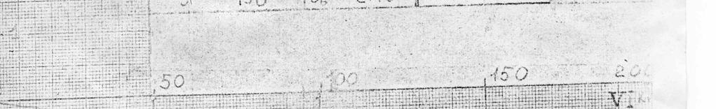
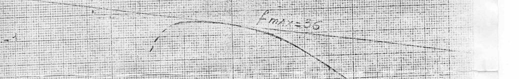
19 C-30 "Edel Weiss" Figure 2: polar and speed to fly 15
20 3. Approach and landing The normal procedure requires adjusting the approach speed to keep sufficient maneuverability, as a function of turbulence (about 30% above the stall speed). The airbrakes, which are very effective, enable precision landings. It is thus recommended, as far as possible, to make long approaches, particularly if there is an obstacle at the entrance of the chosen landing site (tree lines, fences). In this case, approach at about Vi=100 km/h After passing the obstacle: - open the airbrakes to their limit - increase the slope firmly to the chosen touchdown point, round out after it. In rough air, it is prudent to increase the approach Vi to compensate for the turbulence, by as much as 25 km/h. In strong winds with gusts, the approach Vi must be increased by about half of the wind component. For example, for a 50 km/h wind, approach at Vi = 115 km/h. During first flights in this aircraft, we recommend to avoid abrupt changes of airbrakes position near the ground. Any change can change the glide ratio by as much as about 1 to 5, with the consequential effect on the aircraft. Then, when the landing site is assured, choose a medium position for the airbrakes, and maintain it until the start of the roll. The wheel brake control is combined with that of the airbrakes. Remember to never pull the airbrake to the limit at the time of rounding off, to avoid locking the wheel, as at the moment of touchdown, the glider might swing abruptly to the nose. To avoid this movement, use the airbrake cautiously and end the round off with "stick in the belly", in order to touch on "two points". Keep the tailskid pressed strongly to the ground, adding its own friction to that of the main wheel. In case of landing on wet ground, distrust the friction of the tire, and thus the effectiveness of the wheel brake, and foresee a longer rollout as a consequence. We demand pilot conform to the norms of operational maximum Vi, as a function of: - the configuration - The atmospheric turbulence A serious pilot must respect the norms, which he knows from his training period in double-seaters. As to the recommendations, which have a cautionary character, it is particularly suggested to take them in account during the first few flights. 16
21 4. Emergency Procedures a) Emergency Canopy Jettison i. Canopy lock open red handle forward ii. Canopy jettison handle lift cover and pull red handle firmly iii. Canopy - push up, if needed iv. Canopy will separate with instrument panel, allowing clean exit of legs b) Emergency Exit i. Canopy jettison ii. Seat harness open iii. Exit Lift with arms over cockpit rim push yourself away from sailplane iv. Preferably dive under wing, to avoid the tail c) Stall Recovery i. Warning: 1. Buffeting prior to entry; (around 70 km/h for weight under 350 kg) 2. Aileron effectiveness reduced 3. Sink rate increases considerably ii. Termination - Stick forward to neutral iii. Stalling speed At weight below 350kg: lower than 65 km/h d) Spin Recovery i. Use the following procedure: 1. a. Stick release to central position b. Rudder full deflection opposite to spin rotation 2. When rotation stops: a. Rudder - centralize 3. When airspeed build up: a. Elevator smooth pull-out to the horizon; ii. If procedure above fails, try changing aerodynamic configuration, by: 1. Use of airbrakes 2. Use ailerons with the spin rotation to attempt to decrease the more stalled wing s angle of attack 3. Pull elevator back to attempt to reattach the airflow to the elevator surface and than push forward to brake angle of attack. END of Operation Manual 17
LS7 WL, VH-XJB INFORMATION FOR PILOTS
 LS7 WL, VH-XJB INFORMATION FOR PILOTS John Hudson (Revised April 2017) TABLE OF CONTENTS 1. General Information/Specifications 2. Handling Notes 3. Technical Details 4. Daily Inspection 5. Water Ballast
LS4-a VH-XOK INFORMATION FOR PILOTS
 LS4-a VH-XOK INFORMATION FOR PILOTS John Hudson (Revised April 2017) TABLE OF CONTENTS 1. General Information/Specifications 2. Rigging 3. Handling Notes 4. Water Ballast System 5. Radio The LS4a XOK is
Ops Manual 05 Page 40
 Ops Manual 05 Page 40 Ops Manual 05 Pg 41 I. PRE -FLIGHT PREPARATION. (a) EXTERNAL CHECKS --Before entering the cockpit, a detailed inspection of the sailplane for proper condition should be carried out
Pre Solo Written For Schweizer 2-33 Glider. Eagles Sport Aviation Club
 Pre Solo Written For Schweizer 2-33 Glider Eagles Sport Aviation Club Student Date: Instructor 1) What is the maximum gross weight for the 2-33? Empty Weight? 2) What position should the trim level be
DISCLAIMER: This scanned version of the Schweizer 2-33A Sailplane manual is provided without warranty of completeness or accuracy.
 DISCLAIMER: This scanned version of the Schweizer 2-33A Sailplane manual is provided without warranty of completeness or accuracy. It is solely as a service to builders of scale model aircraft who are
SAILPLANE FLIGHT MANUAL
 WSK "PZL-ŚWIDNIK" S.A. Al. Lotników Polskich 1, 21-045 Świdnik, POLAND SAILPLANE FLIGHT MANUAL Type: PW-6U Serial No.: Registration: Document No.: PW-6U / IUL / I / 03 US M Date of Issue: November 18,
Pilot Handling Guide
 Pilot Handling Guide Puchacz SZD-50-3 VH- GRI + WQX These notes are a conversion guide only and not a substitute for the Manufacturer s Flight Manual. General notes on conversions.2 Basic overview.2 External
BASIC AIRCRAFT STRUCTURES
 Slide 1 BASIC AIRCRAFT STRUCTURES The basic aircraft structure serves multiple purposes. Such as aircraft aerodynamics; which indicates how smooth the aircraft flies thru the air (The Skelton of the aircraft
Flight Control Systems Introduction
 Flight Control Systems Introduction Dr Slide 1 Flight Control System A Flight Control System (FCS) consists of the flight control surfaces, the respective cockpit controls, connecting linkage, and necessary
SAILPLANE FLIGHT MANUAL
 WSK "PZL-ŚWIDNIK" S.A. Al. Lotników Polskich 1, 21-045 Świdnik, POLAND SAILPLANE FLIGHT MANUAL Type: PW-6U Serial No.: Registration: Document No.: PW-6U / IUL / I / 03 US M Date of Issue: November 18,
II.E. Airplane Flight Controls
 References: FAA-H-8083-3; FAA-8083-3-25 Objectives Key Elements Elements Schedule Equipment IP s Actions SP s Actions Completion Standards The student should develop knowledge of the elements related to
Principles of glider flight
 Principles of glider flight [ Lecture 2: Control and stability ] Richard Lancaster Email: Richard@RJPLancaster.net Twitter: @RJPLancaster ASK-21 illustrations Copyright 1983 Alexander Schleicher GmbH &
FLIGHT MANUAL. for a sailplane. Allstar PZL Glider Sp. z o.o. SZD-54-2 Perkoz. Serial No: Registration:
 Allstar PZL Glider Sp. z o.o. for a sailplane Model: Serial No: Registration: SZD-54-2 THIS SAILPLANE IS TO BE OPERATED IN COMPLIANCE WITH INFORMATION AND LIMITATIONS CONTAINED HEREIN. THIS DOCUMENT SHOULD
Annex E(M) - Final inspection checklist - monowheel
 - Final inspection checklist - monowheel") Annex E(M) - Final inspection checklist - monowheel A/C Reg... Owner...Kit S/N...Date... (U.K. Only) L.A.A No...Inspector...Insp. No... Note: This check list only covers specific items for inspection of
Annex E(M) - Final inspection checklist - monowheel A/C Reg... Owner...Kit S/N...Date... (U.K. Only) L.A.A No...Inspector...Insp. No... Note: This check list only covers specific items for inspection of
AIRCRAFT PRIMARY CONTROLS A I R C R A F T G E N E R A L K N O W L E D G E
 1.02.02 AIRCRAFT PRIMARY CONTROLS 1. 0 2 A I R C R A F T G E N E R A L K N O W L E D G E CONTROLLING AIRCRAFT AIRCRAFT CONTROL SYSTEM In general, we use control inputs of the following devices in cabin:
Southern Eagles Soaring
 Southern Eagles Soaring N56LS Standard Cirrus Disassembly / Assembly Procedure. Version 2, 2017 You landed out so what now? First, hopefully you made arrangements with someone who has a hitch on their
A103 AERODYNAMIC PRINCIPLES
 A103 AERODYNAMIC PRINCIPLES References: FAA-H-8083-25A, Pilot s Handbook of Aeronautical Knowledge, Chapter 3 (pgs 4-10) and Chapter 4 (pgs 1-39) OBJECTIVE: Students will understand the fundamental aerodynamic
PILOT S NOTES FOR THE BLANIK L-13 SAILPLANE
 Czechoslavak Aeronautical Works PILOT S NOTES FOR THE BLANIK L-13 SAILPLANE 2nd REVISED EDITION - 1967 AERONAUTICAL WORKS - LET KUNOVICE - CZECHOSLOVAKIA PILOT S NOTES FOR THE BLANIK L-13 SAILPLANE 2 FOREWORD
L-23 Super Blanik Rigging (assembly/disassembly) Guide Maj Carl Kerns
 Guide Maj Carl Kerns") L-23 Super Blanik Rigging (assembly/disassembly) Guide Maj Carl Kerns The L-23 Blanik is a difficult Sailplane to rig (assemble). The wings are heavy and are secured via a single
L-23 Super Blanik Rigging (assembly/disassembly) Guide Maj Carl Kerns The L-23 Blanik is a difficult Sailplane to rig (assemble). The wings are heavy and are secured via a single
Winnipeg Headingley Aero Modellers. Things About Airplanes.
 Winnipeg Headingley Aero Modellers Things About Airplanes. Table of Contents Introduction...2 The Airplane...2 How the Airplane is Controlled...3 How the Airplane Flies...6 Lift...6 Weight...8 Thrust...9
Aerodynamic Terms. Angle of attack is the angle between the relative wind and the wing chord line. [Figure 2-2] Leading edge. Upper camber.
![Aerodynamic Terms. Angle of attack is the angle between the relative wind and the wing chord line. [Figure 2-2] Leading edge. Upper camber.](/thumbs/82/86661300.jpg "Aerodynamic Terms. Angle of attack is the angle between the relative wind and the wing chord line. [Figure 2-2] Leading edge. Upper camber.") Chapters 2 and 3 of the Pilot s Handbook of Aeronautical Knowledge (FAA-H-8083-25) apply to powered parachutes and are a prerequisite to reading this book. This chapter will focus on the aerodynamic fundamentals
Chapters 2 and 3 of the Pilot s Handbook of Aeronautical Knowledge (FAA-H-8083-25) apply to powered parachutes and are a prerequisite to reading this book. This chapter will focus on the aerodynamic fundamentals
Brief Maintenance Manual DAR-Solo
 Brief Maintenance Manual DAR-Solo Sofia 2009 Page: 1 TABLE OF CONTENTS Introduction 3 Limitations and safety information 4 General view of DAR-Solo prototype 7 Technical Data 8 Inspection before and after
VIII.A. Straight and Level Flight
 VIII.A. Straight and Level Flight References: FAA-H-8083-3; FAA-H-8083-25 Objectives Key Elements Elements Schedule Equipment IP s Actions SP s Actions Completion Standards The student should develop the
PRIMARY FLIGHT CONTROLS. AILERONS Ailerons control roll about the longitudinal axis. The ailerons are attached to the outboard trailing edge of
 Aircraft flight control systems are classified as primary and secondary. The primary control systems consist of those that are required to safely control an airplane during flight. These include the ailerons,
VIII.A. Straight and Level Flight
 VIII.A. Straight and Level Flight References: FAA-H-8083-3; FAA-H-8083-25 Objectives Key Elements Elements Schedule Equipment IP s Actions SP s Actions Completion Standards The student should develop the
C-130 Reduction in Directional Stability at Low Dynamic Pressure and High Power Settings
 C-130 Reduction in Directional Stability at Low Dynamic Pressure and High Power Settings The C-130 experiences a marked reduction of directional stability at low dynamic pressures, high power settings,
ANNEX TO TYPE CERTIFICATE No. ULL - 07 / 2003 a
 Letecká amatérská asociace ČR, Light Aircraft Association CR Ke Kablu 289, 102 00 Praha 10, Hostivař tel: sekretariát 271 085 270 fax: 27 10 85 596 e-mail: laacr@laacr.cz http://www.laacr.cz Type certificate
Логотип. Hangglider PHANTOM. Manual
 Логотип Hangglider PHANTOM Manual Kiev, Ukraine 2005 TABLE OF CONTENTS Section 1. General information 1.1. Introduction 1.2. Main data 1.3. Operation limitations 1.4. Flying tests Section 2. Set up procedure
Tecnam Eaglet Standard Operating Procedures and Maneuvers Supplement
 Tecnam Eaglet Standard Operating Procedures and Maneuvers Supplement Normal Takeoff Flaps Take Off Trim set Fuel pump on Check for traffic Line up on white stripe Full power Stick should be located in
Flight Manual LS1-f. 0 Amendments, list of effective pages, table of contents
 0 Amendments, list of effective pages, table of contents 0.1 Amendments Any revision of the present manual, except actual weighing data, must be recorded in the following table and in case of approved
XI.B. Power-On Stalls
 XI.B. Power-On Stalls References: AC 61-67; FAA-H-8083-3; POH/AFM Objectives Key Elements Elements Schedule Equipment IP s Actions SP s Actions Completion Standards The student should develop knowledge
XI.C. Power-Off Stalls
 References: FAA-H-8083-3; POH/AFM Objectives Key Elements Elements Schedule Equipment IP s Actions SP s Actions Completion Standards The student should develop knowledge of stalls regarding aerodynamics,
Ottawa Remote Control Club Wings Program
 + Ottawa Remote Control Club Wings Program Guide line By Shahram Ghorashi Chief Flying Instructor Table of Contents Rule and regulation Quiz 3 Purpose of the program 4 Theory of flight Thrust 4 Drag 4
CIRCLING THE HOLIGHAUS WAY -
 CIRCLING THE HOLIGHAUS WAY - OR DO YOU REALLY WANT TO KEEP THE YAW STRING CENTERED? BY RICHARD H. JOHNSON ANSWERS: 1. During Straight Flight - YES, that minimizes drag and maximizes the sailplane's performance.
Improvement of an Artificial Stall Warning System for Sailplanes
 Improvement of an Artificial Stall Warning System for Sailplanes Loek M. M. Boermans and Bart Berendsen Delft University of Technology, Faculty of Aerospace Engineering P.O.Box 5058, 2600 GB Delft, The
Stability and Flight Controls
 Stability and Flight Controls Three Axes of Flight Longitudinal (green) Nose to tail Lateral (blue) Wing tip to Wing tip Vertical (red) Top to bottom Arm Moment Force Controls The Flight Controls Pitch
Front Cover Picture Mark Rasmussen - Fotolia.com
 Flight Maneuvers And Stick and Rudder Skills A complete learn to fly handbook by one of aviation s most knowledgeable and experienced flight instructors Front Cover Picture Mark Rasmussen - Fotolia.com
Lesson: Pitch Trim. Materials / Equipment Publications o Flight Training Manual for Gliders (Holtz) Lesson 4.4 Using the Trim Control.
 Lesson 4.4 Using the Trim Control.") 11/18/2015 Pitch Trim Page 1 Lesson: Pitch Trim Objectives: o Knowledge o An understanding of the aerodynamics related to longitudinal (pitch) stability o Skill o Use of the pitch trim system to control
11/18/2015 Pitch Trim Page 1 Lesson: Pitch Trim Objectives: o Knowledge o An understanding of the aerodynamics related to longitudinal (pitch) stability o Skill o Use of the pitch trim system to control
NORMAL TAKEOFF AND CLIMB
 NORMAL TAKEOFF AND CLIMB CROSSWIND TAKEOFF AND CLIMB The normal takeoff is one in which the airplane is headed directly into the wind or the wind is very light, and the takeoff surface is firm with no
DIRECCION DE PERSONAL AERONAUTICO DPTO. DE INSTRUCCION PREGUNTAS Y OPCIONES POR TEMA
 MT DIREION DE PERSONL ERONUTIO DPTO. DE INSTRUION PREGUNTS Y OPIONES POR TEM 1 TEM: 0292 FLT/DSP - (HP. 03) ERODYNMIS OD_PREG: PREG20084823 (8324) PREGUNT: When are inboard ailerons normally used? Low-speed
robart HOW-TO Series Model Incidence Meter
 robart HOW-TO Series Model Incidence Meter The term incidence is something of a misnomer since this highly versatile tool is capable of measuring or comparing angles other than incidence of a wing or tail.
DIRECCION DE PERSONAL AERONAUTICO DPTO. DE INSTRUCCION PREGUNTAS Y OPCIONES POR TEMA
 MT DIREION DE PERSONL ERONUTIO DPTO. DE INSTRUION PREGUNTS Y OPIONES POR TEM 1 TEM: 0114 TP - (HP. 03) ERODYNMIS OD_PREG: PREG20078023 (8358) PREGUNT: What is the safest and most efficient takeoff and
Attitude Instrument Flying and Aerodynamics
 Attitude Instrument Flying and Aerodynamics 2.1 TURNS 1. An airplane requires a sideward force to make it turn. a. When the airplane is banked, lift (which acts perpendicular to the wingspan) acts not
Flight Controls. Chapter 5. Introduction
 Chapter 5 Flight Controls Introduction This chapter focuses on the flight control systems a pilot uses to control the forces of flight, and the aircraft s direction and attitude. It should be noted that
X-29 Canard Jet. A Simple Depron Foam Build.
 X-29 Canard Jet. A Simple Depron Foam Build. Two full sized X-29 s were built and the first flew in 1984. They were experimental aircraft, testing this unusual configuration of a canard jet with swept
FFI Formation Guidelines and Standard Procedures Mooney Supplement (28 Dec, 2018; Rev 12)
") FFI Formation Guidelines and Standard Procedures Mooney Supplement (28 Dec, 2018; Rev 12) This document describes formation flight differences between RV and Mooney aircraft. In conjunction with the FFI
FFI Formation Guidelines and Standard Procedures Mooney Supplement (28 Dec, 2018; Rev 12) This document describes formation flight differences between RV and Mooney aircraft. In conjunction with the FFI
Visualized Flight Maneuvers Handbook
 Visualized Flight Maneuvers Handbook For High Wing Aircraft Third Edition For Instructors and Students Aviation Supplies & Academics, Inc. Newcastle, Washington Visualized Flight Maneuvers Handbook for
Building Instructions ME 163 B 1a M 1:5 Turbine
 Building Instructions ME 163 B 1a M 1:5 Turbine Thank you for choosing our kit of the Me-163B. We ask you to read the instruction once in advance before building this kit in order to avoid mistakes. Make
Homework Exercise to prepare for Class #2.
 Homework Exercise to prepare for Class #2. Answer these on notebook paper then correct or improve your answers (using another color) by referring to the answer sheet. 1. Identify the major components depicted
Related Careers: Aircraft Instrument Repairer Aircraft Designer Aircraft Engineer Aircraft Electronics Specialist Aircraft Mechanic Pilot US Military
 Airplane Design and Flight Fascination with Flight Objective: 1. You will be able to define the basic terms related to airplane flight. 2. You will test fly your airplane and make adjustments to improve
BlueArrow. Venus DLG. Construction and Flight Manual. Note: Read this manual carefully before construction and flight!
 BlueArrow Venus DLG Construction and Flight Manual Note: Read this manual carefully before construction and flight! 1 1. Introduction Thank you for choosing this fantastic Venus DLG brought to you by BlueArrow
CHAPTER 9 PROPELLERS
 CHAPTER 9 CHAPTER 9 PROPELLERS CONTENTS PAGE How Lift is Generated 02 Helix Angle 04 Blade Angle of Attack and Helix Angle Changes 06 Variable Blade Angle Mechanism 08 Blade Angles 10 Blade Twist 12 PROPELLERS
Alexander Schleichers ASG 29. Sneak into the Design Process
 Alexander Schleichers ASG 29 Sneak into the Design Process Overview Introduction What is the ASG 29? Going into Detail Shaping the Ship: Aerodynamics Flaperons under Control: Control Systems Getting into
FAA-S-ACS-6 June 2016 Private Pilot Airplane Airman Certification Standards. Task ACS Settings
 FAA-S-ACS-6 June 2016 Private Pilot Airplane Airman Certification Standards Cessna 172: mixture rich, carb heat out if below the green arc. Clearing Turns all manuevers! Task ACS Settings Traffic Pattern
LAPL(A)/PPL(A) question bank FCL.215, FCL.120 Rev PRINCIPLES OF FLIGHT 080
/PPL(A) question bank FCL.215, FCL.120 Rev PRINCIPLES OF FLIGHT 080") PRINCIPLES OF FLIGHT 080 1 Density: Is unaffected by temperature change. Increases with altitude increase. Reduces with temperature reduction. Reduces with altitude increase. 2 The air pressure that acts
PRINCIPLES OF FLIGHT 080 1 Density: Is unaffected by temperature change. Increases with altitude increase. Reduces with temperature reduction. Reduces with altitude increase. 2 The air pressure that acts
Normal T/O Procedure. Short Field T/O Procedure
 Normal T/O Procedure Add full power: Engine Instruments green Airspeed alive 1,000 AGL Accelerate to enroute climb 85 KIAS Complete climb check Vr = 55-60 Vy 79 KIAS Prior to Receiving T/O Clearance Complete
Aerodynamics Principles
 Aerodynamics Principles Stage 1 Ground Lesson 3 Chapter 3 / Pages 2-18 3:00 Hrs Harold E. Calderon AGI, CFI, CFII, and MEI Lesson Objectives Become familiar with the four forces of flight, aerodynamic
Cessna 172S Skyhawk Standardization Manual
 Cessna 172S Skyhawk Standardization Manual This manual is to be utilized in conjunction with the manufacturers approved POH/ AFM and the Airplane Flying Handbook (FAA-H-8083-3A). This manual should be
Jabiru J230-SP Section 10
 Jabiru J230-SP Section 10 Section 10 10.1 Introduction This section contains information on the basic flight controls, door operation, and entry and egress, followed by a flight training outline compiled
SUPPLEMENT TO AIRCRAFT FLIGHT MANUAL FOR MOTOR-DRIVEN ROPE WINCH TYPE RPM 11/01
 SUPPLEMENT TO AIRCRAFT FLIGHT MANUAL FOR MOTOR-DRIVEN ROPE WINCH TYPE RPM 11/01 (Langenthaler-Winch) Aircraft-Manufacturer: Avions Robin SA Type of Aircraft: Robin DR 300-180R DR400-180R DR 400-200R DR
aero naut Electric Model Aeroplane Quido Order-No. 1303/00
 aero naut Electric Model Aeroplane Quido Order-No. 1303/00 Quido is a small model that accompanies you wherever you go. The prefabricated parts are mostly balsa and just need to be assembled according
XI.D. Crossed-Control Stalls
 References: FAA-H-8083-3; POH/AFM Objectives Key Elements Elements Schedule Equipment IP s Actions SP s Actions Completion Standards The student should understand the dynamics of a crossed-control stall
The canard. Why such a configuration? Credit : Jean-François Edange
 The canard Why such a configuration? Credit : Jean-François Edange N obody doubtless knows that a great majority of light or heavy planes share a common design. Schematically, we find a fuselage, wings
CIVIL AIR PATROL United States Air Force Auxiliary Cadet Program Directorate. Cessna 172 Maneuvers and Procedures
 CIVIL AIR PATROL United States Air Force Auxiliary Cadet Program Directorate Cessna 172 Maneuvers and Procedures This study guide is designed for the National Flight Academy Ground School. The information
POWERED FLIGHT HOVERING FLIGHT
 Once a helicopter leaves the ground, it is acted upon by the four aerodynamic forces. In this chapter, we will examine these forces as they relate to flight maneuvers. POWERED FLIGHT In powered flight
CIRRUS AIRPLANE MAINTENANCE MANUAL MODELS SR22 AND SR22T CHAPTER 55-40: RUDDER GENERAL. Rudder 55-40: RUDDER. 1. General
 CIRRUS AIRPLANE MAINTENANCE MANUAL Rudder CHAPTER 55-40: RUDDER GENERAL 55-40: RUDDER 1. General The rudder provides airplane directional (yaw) control and includes a rudder trim tab used for yaw trim
Build This World Record Fuselage Model
 Build This World Record Fuselage Model Here You Have Complete Instructions and Plans to Build a Plane of Sure-fire Performance that Established a World Record at the 1932 National Airplane Model Competition
Dornier Do R 4 Super-Wal
 Dornier Do R 4 Super-Wal Model Aviation Laddie Mikulasko s Dornier Do R 4 Super-Wal Build the multiengine, record-setting seaplane. Article, plans, instructions, and photos by Laddie Mikulasko. Complete
"Aircraft setup is a constant process really. Every
 The R/C Aircraft Proving Grounds - Aerobatics Setup Set Up for Success by: Douglas Cronkhite "Aircraft setup is a constant process really. Every time something is changed, there is the chance it will affect
PERFORMANCE MANEUVERS
 Ch 09.qxd 5/7/04 8:14 AM Page 9-1 PERFORMANCE MANEUVERS Performance maneuvers are used to develop a high degree of pilot skill. They aid the pilot in analyzing the forces acting on the airplane and in
TAILWHEEL AIRPLANES LANDING GEAR TAXIING
 Ch 13.qxd 5/7/04 10:04 AM Page 13-1 TAILWHEEL AIRPLANES Tailwheel airplanes are often referred to as conventional gear airplanes. Due to their design and structure, tailwheel airplanes exhibit operational
Mini Glider Manual. Your Glider comes partially assembled. The front wheel and the handlebars require assembly.
 Mini Glider Manual Congratulations on your purchase of the Mini Glider! Your glider is designed for years of nearly carefree use by your child. These instructions include how to set up your glider and
EZee Glider Manual. Tools needed for Assembly: Wrench (included) Philips Screwdriver (not included) Assembly Instructions
 Philips Screwdriver (not included) Assembly Instructions") EZee Glider Manual Congratulations on your purchase of the EZee Glider! Your glider is designed for years of nearly carefree use by your child. These instructions include how to set up your glider and
EZee Glider Manual Congratulations on your purchase of the EZee Glider! Your glider is designed for years of nearly carefree use by your child. These instructions include how to set up your glider and
Bugatti 100P Longitudinal Stick Forces Revision A
 Bugatti 1P Longitudinal Stick Forces Revision A Stick-free static longitudinal stability (stick force-per-knot) and stick-free longitudinal maneuvering stability (stick force-per-g) were computed for the
Cessna 152 Standardization Manual
 Cessna 152 Standardization Manual This manual is to be utilized in conjunction with the manufacturers approved POH/ AFM and the Airplane Flying Handbook (FAA-H-8083-3A). This manual should be used as a
PROCEDURES GUIDE. FLIGHT MANEUVERS for the SPORT PILOT
 Page 1 of 10 PROCEDURES GUIDE FLIGHT MANEUVERS for the SPORT PILOT * Author s Note: Whereas this procedures guide has been written for a specific application, it can easily be modified to fit many different
Advanced Aerobatic Airplane Guidelines
 Note: The following information might upset career aerodynamicists because it does not also include explanations of Mean Aerodynamic Center, Decalage, Neutral Point, and more when describing how to achieve
Gleim Private Pilot Flight Maneuvers Seventh Edition, 1st Printing Updates February 2018
 Page 1 of 11 Gleim Private Pilot Flight Maneuvers Seventh Edition, 1st Printing Updates February 2018 If you are tested on any content not represented in our materials or this update, please share this
LAPL/PPL question bank FCL.215, FCL.120 Rev PRINCIPLES OF FLIGHT 080
 LAPL/PPL question bank FCL.215, FCL.120 Rev. 1.7 11.10.2018 PRINCIPLES OF FLIGHT 080 1 Density: Reduces with temperature reduction. Increases with altitude increase. Reduces with altitude increase. Is
Flight Manual Schleicher ASK 21 3
 Flight Manual Schleicher ASK 21 3 I.3 Contents I. General I.1 Log of revisions I.2 Pages included I.3 Contents I.4 3-Side-View I.5 Description (Beginning of JAR22-required and LBA-approved part.) II. Operating
Preliminary Design Review (PDR) Aerodynamics #2 AAE-451 Aircraft Design
 Aerodynamics #2 AAE-451 Aircraft Design") Preliminary Design Review (PDR) Aerodynamics #2 AAE-451 Aircraft Design Aircraft Geometry (highlight any significant revisions since Aerodynamics PDR #1) Airfoil section for wing, vertical and horizontal
Preliminary Design Review (PDR) Aerodynamics #2 AAE-451 Aircraft Design Aircraft Geometry (highlight any significant revisions since Aerodynamics PDR #1) Airfoil section for wing, vertical and horizontal
CIRRUS AIRPLANE MAINTENANCE MANUAL
 RUDDER 1. GENERAL The rudder provides airplane directional (yaw) control and includes a rudder trim tab used for yaw trim adjustment. The rudder is of conventional design with skin, spar and ribs manufactured
LAA TYPE ACCEPTANCE DATA SHEET TADS 315 EV-97 AND EV-97A EUROSTAR. Issue 6 SB EV97-UK-08 and 09 added dated
 Issue 6 SB EV97-UK-08 and 09 added dated 26.3.08 1. UK contact Nigel Beale, Cosmik Aviation, Burnside, Deppers Bridge, Southam, Warks, CV47 2SU. Tel: 07940 266521. E-mail: cosmik@skydrive.co.uk 2. Description
Pre-Paint>Fuselage>Empennage>Fit vertical tail fin. Objectives of this task: Materials and equipment required: Fit the spar extender
 Pre-Paint>Fuselage>Empennage>Fit vertical tail fin Objectives of this task: To fit the vertical tail fin to the fuselage, including fitting the static probe, static tube, optional strobe light wiring and
Chapter 3: Aircraft Construction
 Chapter 3: Aircraft Construction p. 1-3 1. Aircraft Design, Certification, and Airworthiness 1.1. Replace the letters A, B, C, and D by the appropriate name of aircraft component A: B: C: D: E: A = Empennage,
BUILDING INSTRUCTION Glider TASER unplugged. Taser unplugged Building instruction September
 Wingspan [mm]: 2000 Takeoff weight [g]: From 400 Airfoil: AG 455ct-02f AG47ct-02f by Mark Drela BUILDING INSTRUCTION Glider TASER unplugged www.pcm.at 1 CONTENTS DATA 1. Kit contents 2. What else do you
MANEUVERS GUIDE. Liberty Aerospace 1383 General Aviation Drive Melbourne, FL (800)
") MANEUVERS GUIDE Liberty Aerospace 1383 General Aviation Drive Melbourne, FL 32935 (800) 759-5953 www.libertyaircraft.com Normal/Crosswind Takeoff and Climb 1. Complete the runup and before takeoff checklist.
MANEUVERS GUIDE Liberty Aerospace 1383 General Aviation Drive Melbourne, FL 32935 (800) 759-5953 www.libertyaircraft.com Normal/Crosswind Takeoff and Climb 1. Complete the runup and before takeoff checklist.
RB70 Automatic Diluent Valve Maintenance Manual. Version 1.1 November 2006 Written by Tino de Rijk. Page 1 of 23
 RB70 Automatic Diluent Valve Maintenance Manual Version 1.1 November 2006 Written by Tino de Rijk Page 1 of 23 Table of Contents 1. Introduction... 3 2. ADV diagram and parts list (Pre June 2006)... 4
AVA Building Instructions
 Suggested Assembly Sequence: AVA Building Instructions 1. Insert fittings in rudder and trial fit rudder on boom 2. Attach stab to v-mount and position ahead of rudder ¼, sanding the v-mount as needed.
Compiled by Matt Zagoren
 The information provided in this document is to be used during simulated flight only and is not intended to be used in real life. Attention VA's - you may post this file on your site for download. Please
ROTORCRAFT FLIGHT MANUAL SUPPLEMENT. TO THE BELL MODEL UH-1H ROTORCRAFT FLIGHT MANUAL for the APICAL EMERGENCY FLOAT KIT
 SUPPLEMENT TO THE for the APICAL EMERGENCY FLOAT KIT This supplement is to be used when the rotorcraft is modified by the installation of the Apical Float Kit 644.3201 for UH-1H helicopters. The information
HIGH PERFORMANCE SAILPLANE ENDORSEMENT
 HIGH PERFORMANCE SAILPLANE ENDORSEMENT ENGINEERING, DATA AND PERFORMANCE TYPE Name : Instructor: GFA: GFA: (Signature/Name) Satisfactorily Completed on: / / 1 THE ENDORSEMENT QUESTIONNAIRE In order to
DEFINITIONS. Aerofoil
 Aerofoil DEFINITIONS An aerofoil is a device designed to produce more lift (or thrust) than drag when air flows over it. Angle of Attack This is the angle between the chord line of the aerofoil and the
Aviation Merit Badge Knowledge Check
 Aviation Merit Badge Knowledge Check Name: Troop: Location: Test Score: Total: Each question is worth 2.5 points. 70% is passing Dan Beard Council Aviation Knowledge Check 1 Question 1: The upward acting
Trimming and Flying a Hand Launch Glider A basic and beginners guide by Kevin Moseley
 Trimming and Flying a Hand Launch Glider A basic and beginners guide by Kevin Moseley First and foremost, I am by no means a master at what I have done, or do, in hlg or the class. I am fortunate enough
Stalls and Spins. Tom Johnson CFIG
 Stalls and Spins Tom Johnson CFIG Contents Angle of Attack Stall Recognition and Recovery Spin Entry and Recovery Load Limit Considerations Gust Induced Stall and Spin Accidents Stalls a stall is a loss
CESSNA 172-SP PRIVATE & COMMERCIAL COURSE
 CESSNA 172-SP PRIVATE & COMMERCIAL COURSE University of Dubuque INTENTIONALLY LEFT BLANK Revision 1 Standard Operating Procedures 1 CALLOUTS CONDITION Parking Brake Released After Takeoff Power has been
Akcent-2 - Building Instructions
 Akcent-2 Home Pictures Building Instructions Ordering Akcent-2 - Building Instructions Note! The pictures show older kits with "diser" wings. The new kits come with nicer D-box wings. Servo locations are
Climbs, descents, turns, and stalls These are some of the maneuvers you'll practice, and practice, and practice By David Montoya
 Climbs, descents, turns, and stalls These are some of the maneuvers you'll practice, and practice, and practice By David Montoya Air work stalls, steep turns, climbs, descents, slow flight is the one element
Student Pilot s Guide
 Student Pilot s Guide The Cirrus SR22 is a remarkably simple, safe and easy aircraft to fly. Angelina Jolie flying her own Cirrus. Key Words 1. My Airplane or I ve got it - means to let go of all controls