Euromodel Royal William 08.Yards.November.2017
|
|
|
- Grant Clyde Short
- 5 years ago
- Views:
Transcription

1 TRANSLATION LINKS 1. type into your browser... english+italian+glossary+nautical terms 2. utilise the translation dictionary Nautical Terms & Expressions from Euromodel website An interpretive build of the Royal William 1 st. Rate English Vessel Originally launched in 1670 as the 100-gun HMS Prince Re-built and launched in 1692 as the HMS Royal William Final re-build and... Launched 1719 Scale 1:72 Checked the Essential Resource Information File? 08.YARDS November 2017 This interpretive build is based on the supplied drawings, the kit material and an amount of extra material. This work only illustrates how this ship might be built.the level of complexity chosen is up to the individual This resource information was based on the original text supplied by Euromodel and then expanded in detail as the actual ship was constructed by MSW member piratepete007. [Additional & exceptional support was gratefully received from MSW members marktiedens, Ken 335 and Vince P. My sincere thanks to them and other MSW members] Neither the author or Euromodel have any commercial interest in this information and it is published on the Euromodel web site in good faith for other persons who may wish to build this ship. Euromodel does not accept any responsibility for the contents that follow. 1

2 Euromodel is the firm that, with your experience, skills, and fantasy allows you to realize the ship of your dreams Photo courtesy of Vic Yancovitch 2

3 This is not an instructional manual but is a collaboration amongst a number of MSW members whose interpretations were based on the drawings and the supplied kit. Additional material used was dictated by my own personal choices. Greater simplification would be achieved by using the material as it is supplied. Model Ship World Forum Various members who were, or are, involved in their own build of the Royal William have allowed the inclusion of photos from their posts and many of their ideas and methods - in the belief that this will serve as a stimulus and an interest to new builders of this ship. So grateful thanks go to Brian C; Denis R; KeithW; marktiedens; Vince P; Ken3335, BillLib They have taken the RW build to a much higher level than intended by this kit. Reference Texts Fighting at Sea in the Eighteenth Century; The Art of Sailing Warfare by Sam Willis (2008) Historic Ship Models by Wolfram zu Mondfeld (1989) Seventeenth Century Rigging by R.C. Anderson (1955) [almost a complete copy of his earlier book The Rigging of Ships in the Days of the Spritsail Topmast, (1927) ] The Construction and Fitting of the English Man of War by Peter Goodwin (1984) The Masting and Rigging of English Ships of War by James Lee (1984). Growing Specific Shapes for Ship Timbers 3
4 [To navigate through the contents use control + click ] Contents RECENT FILE CHANGES... 6 Colour Dilemma... 7 Chapter 1: DIMENSIONS & TRANSLATIONS... 8 Spar Nomenclature... 8 Spar Dimensions... 9 Spar and Yard Translations Plan Sheet Translations (12 15) Chapter 2: YARDS Yard Construction Forming Battens from the Supplied Timber Rods Creating Battens using Extra Material Cleats Stuns l Booms & Irons Discussion Outer & Inner Iron Construction Yard Rigging Foot Ropes and Stirrups Topgallant Yard Footropes? Accuracy in Rigging Basic Construction Advanced Construction Parrels
5 Illustrations [The figures below are not hyperlinked] Figure 1: Hole for Outer Iron Figure 2: Battens on the Spritsail Yard from the Bowsprit Figure 3: Forming Yard Battens from Yard Rod Supplied Figure 4: Battens Figure 5: Sling Cleat Positioning Figure 6: Simulation of 'Yard Arm Cleats' Figure 7: Sling Cleat Example Figure 8: Diagrammatic View of Topmast Studding Sails (Stuns ls) Figure 9: Outer Iron 'A' Figure 10: Outer Iron 'B' Figure 11: Boom, Yard and Yard Arm Figure 12: Stuns l Boom Position (viewed from aft position) Figure 13: Stuns l Boom Positioned Away From Yard Figure 14: Iron Construction Figure 15: Outer Iron Figure 16: Inner Irons Figure 17: Inner Boom Iron Figure 18: Inner Footrope (diagrammatic) Figure 19: Outer Footrope (diagrammatic) Figure 20: Yard Rigging Figure 21: Stirrup Lashing to Yard Figure 22: Fore and Main Rigging Lines Figure 23: Spritsail Yard Clew Lines Figure 24: Stirrup Seizing, Example A Figure 25: Making the Ropes More Realistic Figure 26: Basic Rigging for Footrope & Stirrup - Diagrammatic Figure 27: Footrope Jig Figure 28: Combinations of Rigging for Footrope & Stirrup - Diagrammatic Figure 29: Footrope Jig (advanced) Figure 30: Forming the Stirrup Eye (advanced) Figure 31: Removing Nail/ Pin from the Eye Figure 32: Creating Footrope Curvature Figure 33: Alternative Method of Making Stirrups Figure 34: Topsail Yard Parrel Figure 35: Rigging a Truck & Rib Parrel Figure 36: Fore, Main & Mizzen Mast Dolphin Parrel Figure 37: Main Yard Dolphin
6 RECENT FILE CHANGES November

7 Colour Dilemma Colour is very much up to the modeler to choose. Whilst the use of colour particularly ochre was common in many British naval ships around this time, many builders choose to leave all timber unpainted with a minimal use of black as depicted on this page. For the more historically inclined, the following comment should be useful yellow lower masts, black from the bibbs to the lower mast cap including the tops; natural varnish finish for the topmasts above the mast cap with again black for the hounds, crosstrees, and topmast cap; varnished top gallant masts with black up to the topmast cap and again for the hounds; yards were usually all black, the studding booms most probably varnished or natural... This raised a dilemma... natural wood or painted black for the yards and studding sail booms? If I went for the painted appearance, it would be more historically correct but would also tend to mask some of the intricate detail of the studding sail boom irons. Nevertheless, I opted for the black painting. If you follow suit, then some of the detail that follows you might consider unnecessary? 7
8 Chapter 1: DIMENSIONS & TRANSLATIONS Spar Nomenclature This list also includes masts...12 x 445mm. (1), 10 x 700 mm. (1) ; 10 x 450 mm. (1) ; 8 x 650 mm. (1); 8 x 675 mm. (1); 6 x 550 mm. (1); 6 x 550 mm. (1); 6 x 420 mm. (1); 5 x 700 mm. (1); 5 x 650 mm. (1); 5 x 200 mm. (1); 4 x 350 mm. (1); 3 x 200 mm. (1); 3 x 660 mm. (1);1 x 580mm. (1) A: Bowsprit Explanatory Note Where the size is described as 7 i.e. 8 mm., this indicates that the drawing diameter is 7 mm. and that 8 mm. has been provided in the kit to allow the builder to reduce the size down to 7 mm. 36: Spritsail Yard Pennone di civada (5 mm.) 37: Upper Spritsail Yard Pennone di controcivada (3 mm.) B: Foremast 38: Fore Yard Pennone di trinchetto (7 i.e. 8 mm.) Studding Sail (stuns l) Booms (4 mm.) 39: Topsail Yard Pennone di parrocchetto (5 mm.) Studding Sail (stuns l) Booms (2 mm.) 40: Topgallant Yard Pennone di velaccio (3.5 i.e. 4 mm.) C: Main Mast D: Mizzen Mast 41: Main Yard Pennone di maestra (9 i.e. 10 mm.) Studding Sail (stuns l) Booms (3 mm.) 42: Topsail Yard Pennone di gabbia (5.5 i.e. 6 mm.) Studding Sail (stuns l) Booms (2 mm.) (according to a table found in Lees, the main stuns l boom had a maximum diameter of 10.5 inches = 3.7 mm. at this scale tapering to a lesser thickness) 43: Topgallant Yard Pennone di velaccio (4.5 i.e. 5 mm.) 44: Mizzen Yard Pennone di mezzana (6 mm.) 45: Topsail Yard Pennone di belvedere (4.5 i.e. 5 mm.) 46: Lateen Antenna di mezzana (5.5 i.e. 6 mm.) 8
9 Spar Dimensions Individual yard section lengths will need to be cut from the longer lengths supplied in the kit. These final lengths (and their diameters) are shown in the table below. The kit lengths (which allow a small excess) are indicated by the grouped shading. Example: Bowsprit Mast 21 and Foremast 25 have finished lengths of 295 and 385 mm. respectively and will be cut from a kit length that is 700 mm. long. The yard + studding sail boom combinations are indicated by broken lines. YARDS, etc Diameters BOWSPRIT No. Lengths FOREMAST MAIN MIZZEN
10 Spar and Yard Translations Fore Main Mizzen velaccino (topgallant) velaccio (topgallant) belvadere (topgallant) - decontrovelaccino - decontrovelaccio - controbelvadere - controvelaccino - controvelaccio - volantebelvadere - velaccino - velaccio - fissobelvadere parrochetto (topmast) gabbia (topmast) contromezzana (topmast) - parrochetto volante - gabbia volante - contromezzana volante - parrochetto fisso - gabbia - contromezzana fissa trinchetto (fore mast) maestro (main mast) mezzana (mizzen mast) 10

11 Plan Sheet Translations (12 15) Plan Sheet 12 Staysails prima sartia prodiera di destra e sinistra seized to first shroud on both sides bozzella tipo F1 su faccia opposta block type F1 on the opposite side per i riferimenti numerici degli alberi e delle coffe vedi tav. 3 per le bandiere vedi tav. 10 per le vele vedi tav. 1 - for the numerical references of the masts and of the tops see Plan Sheet 3; for the flags see Plan Sheet 10; for sails see Plan Sheet 1 fuori scala not to scale Plan Sheet 13 Foremast come bracci di destra on the right side (starboard) faccia poppiera looking towards the stern Fig. opposite... passa perla cavatoia sull serpa e da volta sul parapetto di prora line passes over the Prow Deck, through the ornamentation between the middle rails of the bowsprit and back to the Focs le railing. al paranco come per il pennone di trinchetto as for the tackle for the fore yard of the foremast alla ringhiera del castello to rail on the foc sle deck faccia prodiera looking towards the bow come braccio di parrochetto to the fore topsail yard fuori scala not to scale Plan Sheet 14 Main Mast faccia poppiera facing aft faccia prodiera facing forwards ad anelli sulla coffa to rings on the topmast top legare alla ringhiera di sinistra tie to the railing on the left legare alla ringhiera di destra tie to the railing on the right per I riferimenti dei pennoni vedi tav. 3 for flag pole references, see Plan Sheet 3 paranco come per pennone di maestra hoist as for the main lower yard 11
12 Plan Sheet 15 Mizzen Mast faccia poppiera looking towards the stern faccia prodiera looking towards the bow fa dormiente sull ultima sartia poppiera dell albero di maestra a destra e a sinistra the line is fixed on the last shroud of the Main Mast on both the right and left danne volta a 2 anelli sulla coffa allow for two rings on the top fanno dormienti sullo stroppo delle bigotte della coffa di bompresso make fixed onto the deadeye strop of the bowsprit top Il pennone di mezzana ha la sold funzione di poter tesdre la vela di belvedere - mizzen flagpole has the only function of being able to tension the mizzen topsail. particolare dell attacco della vela al pennone (inferitura) detail of the sail attachment to the flagpole 12
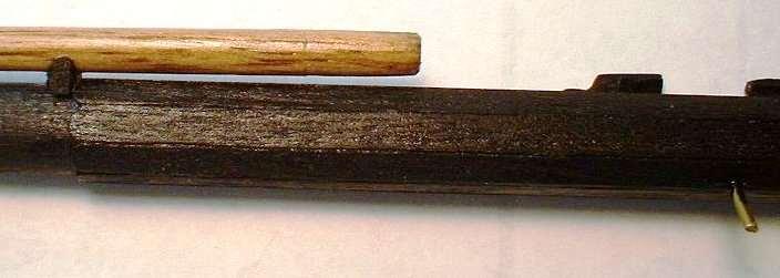
![Yard Construction Chapter 2: YARDS The yards containing studding sail booms are : fore yard [38], main yard [40] and their respective topsail yards [39 & 41].](/docs-images/91/106992081/images/13-0.jpg "At each end, these yards have a small extension termed the yard arms and a small hole (red arrow) needs to be made in their ends to accommodate the outer studding sail boom iron rod.")

13 Yard Construction Chapter 2: YARDS The yards containing studding sail booms are : fore yard [38], main yard [40] and their respective topsail yards [39 & 41]. At each end, these yards have a small extension termed the yard arms and a small hole (red arrow) needs to be made in their ends to accommodate the outer studding sail boom iron rod. It is far better to drill this hole before shaping the yard while the timber is much thicker and therefore stronger. A 0.5 mm. hole was produced. hole to be drilled Figure 1: Hole for Outer Iron At the outset, it was decided to follow the historical style of painting the actual yard black, so what the yard is made from is immaterial. Photographs included in this file tend to mainly unpainted. How the shape is achieved is up to builder and there are some excellent methods of creating these yards by hand - but I utilized a small lathe. Due to the repetitious work, the four yards with the studding sail booms were constructed first. The stuns l booms were left unpainted. Figure 2: Battens on the Spritsail Yard from the Bowsprit Forming Battens from the Supplied Timber Rods From measurements of Plan Sheet 3, the battens that form an octagonal arrangement in the middle of the yard appear to be an integral part of the original yard material. There is no distinction between the height of the battens and the surface of the yard itself. Euromodel has supplied rods that are larger than required (e.g. 8 mm. vs. 7 mm. for the Foreyard) but no batten material. With some careful marking out and filing, this effect can be created from the original rod. In Fig. 2, the spritsail yard on the bowsprit of one model shows the presence of battens which appear to be part of the original rod used to make the yard rather than showing battens added. A similar pattern can be found on all other yards of this model. As a trial, a Main Yard was produced from some scrap material (Fig. 3) and whilst following the cross-section widths at various points along the yard, I managed to manipulate these a little so that some central battens were left slightly raised above the rest of the yard. raised batten flat surfaces Figure 3: Forming Yard Battens from Yard Rod Supplied 13


14 Creating Battens using Extra Material An alternative approach to the above comment is to add the battens in the middle to produce an octagonal effect. Since the kit did not contain any batten material, Improvisation with some 0.5 mm. thick strips was carried out. The ideal construction would see the determination of the correct width for each batten by reference to the outside circumference (diameter x 22/7 x 1/8). Each batten should be slightly larger to allow the edges to be beveled enabling a Figure 4: Battens tighter fit between the battens. As shown in the drawing opposite, the ends of each batten are rounded. In the basic construction, reference was made to simulating the battens using the supplied rod itself. Whilst this can produce the batten effect, it must be remembered that the battens were nailed onto the yard surface and so were slightly raised above the yard surface. Once the battens were in position, some careful sanding was required to produce a uniform surface. an all-important anchoring pin Example of Shaping a Yard Along the Main Yard, it was determined that a mid-length section of mm. was untapered and remained at the stated diameter width of 9.0 mm. The remaining length each side of this was gradually tapered downwards to approx. 2.5 mm. (although it was only worked down to 3 mm.). Be aware that the taper so produced has a small degree of convexity outwards. sling cleats Cleats sling cleats keep all the rigging located in the centre of the yard yard arm cleats stop the braces, lifts and clew earings sliding inwards. Figure 5: Sling Cleat Positioning 14

15 In a basic construction, it is possible to avoid construction of the yard arm cleats by following the shape as indicated in Figure 6. However, if yard arm cleats are to be used, they are illustrated in Fig. 15. Figure 6: Simulation of 'Yard Arm Cleats' Both cleats should be thin but in many models this is often not the case. Sling cleat width should be approx. 1 mm. (and if using them, the yard arm cleats approx. 1.8 mm.). The easiest way of constructing these very small sizes is to glue the correct length on the yard and then trim down to the correct dimensions. The close proximity of each group of cleats also allows them to be trimmed to the same shape. cleats could have been lower Figure 7: Sling Cleat Example 1 15
 were used to increase the sail area when the wind was light and following. They extended the sail cloth out further on either side of the sails normally in use. Using Fig.")
16 Stuns l Booms & Irons Discussion Stunsail boom or more frequently stuns l are naval contractions of the term studding sail boom. Stuns ls (blue shading) were used to increase the sail area when the wind was light and following. They extended the sail cloth out further on either side of the sails normally in use. Using Fig. 8 as an example, the topmast stuns ls (and the lower stuns ls) were set (red lines) from the stuns l booms. However, the topgallant stuns l was set from the topgallant yard. There are four stuns l booms two on each of the Foremast and the Main Mast. Figure 8: Diagrammatic View of Topmast Studding Sails (Stuns ls) Figure 9: Outer Iron 'A' English and most Continental ships positioned the booms in front of the yard at a 45 o angle (Fig. 11) and were attached through inner lashings and two iron rings - irons. The outer ring was held by an iron rod bent at right angles and either inserted into the end of the yard arm (Fig. 10) or held by straps and bolts (Fig. 9) or a combination of both. Figure 10: Outer Iron 'B' Studding sail boom. Boom iron inserted into yard arm. Yard arm Yard In this model, the builder has chosen to replace the yard arm cleats with a simple turned collar. Figure 11: Boom, Yard and Yard Arm 16
.")
17 Stuns l Boom Positioning The drawings in Plan Sheet 3 at first glance appear to portray this boom with rather an odd shape but all is explained when you realize that the drawing is a view from behind the yard with part of the boom obscured. The boom is actually a short distance outwards and upwards in relation to the yard (refer to Fig. 12 below). Studding sail boom (green) diagonally in front of yard. Figure 12: Stuns l Boom Position (viewed from aft position) Figure 13 (below) illustrates the diagram above but also shows the presence of an inner iron which is not evident in the main drawings but is shown as typical in a small drawing near the top right hand corner of Plan Sheet 3 (which was included in this build). Figure 13: Stuns l Boom Positioned Away From Yard 17


18 Outer & Inner Iron Construction The easiest method here is for the simple iron insertion into the yard arm as shown previously in Fig. 10. There would have been a metal cap or a pair of metal jaws over, and set into, the yard arm end and so in a basic build, painting the end black will closely produce the desired effect. A metal strip wrapped around the end and painted black would add a stronger sense of realism. Brass & copper tubing or strips are commonly used to create the metal rings both the inner and outer boom rings need to be loose to allow the boom itself to slide easily. 0.8 mm. brass wire Figure 14: Iron Construction In a model, the booms will be in a fixed position and no allowance is made for their movement. It is often suggested that the boom iron is soldered into the boom ring but as indicated in Fig. 14, the iron is simply inserted into the boom and fixed in position. Outer Irons Figure 15: Outer Iron The iron rod was inserted into the yard arm and the simulation of the metal jaws readily carried out by using black paint to outline the shape. Fig. 15 shows a further possible step by the addition of the jaws/ cap (white dotted lines) that both sealed the open end grain of the boom and ensured the iron would remain in position. The metal jaws were let into the yard arm surface producing a flushed surface. A metal strap was then added to hold the jaws/ cap itself in position. Figure 16: Inner Irons Inner Irons The inner boom iron was located about 1/3 distance from the end of the yard arm. This iron had one ring fitted around the yard with a second ring attached to it via a short rod. The upper, second ring was a loose fit to allow the stuns l boom to slide through it. This ring also frequently had a hinge so that it could be opened. The first band (around the yard) could be formed by using 3.0 mm. black automative pinstripe tape or black card. The outer band could be made from 3.0 mm. brass strip or copper or brass tube. 18 Figure 17: Inner Boom Iron
19 19

20 Yard Rigging Foot Ropes and Stirrups Foot ropes extended aft along the yard and about 760 mm. below it they provided a foothold for crew whilst reefing the sails. The rope of the lower yards was aproximately 24.2 mm. in diameter with the far end having a spliced eye fitted over the yard arm and the inner end made fast behind the sling cleat on the other side of the yard. The ropes were held by short vertical ropes known as stirrups. At this scale of building, the rope diameter would be 0.34 mm. The drawings show 0.5 mm. but 0.4 mm. was used as a compromise. The following figures, taken from Plan Sheet 3, are only diagrammatic but illustrate the principles of foot rope rigging. battens inner lashing of boom foot rope fixed behind mast cleat (not shown) boo m yard arm yard arm cleats foot rope yard stirrup mast centre line Figure 18: Inner Footrope (diagrammatic) The drawings often attempt to show what could be utilized in the ship construction. Examination of Plan Sheet 3 (Fig. 20) shows the rigging in a complex format but in building a typical ship model, such arrangements are often simplified. What is done will be explained in the following pages. Figure 19: Outer Footrope (diagrammatic) Figure 20: Yard Rigging stirrup inner stuns l iron is a modified form but not shown in drawing. Plan Sheet 3 shows THREE rope turns but this sling method is commonly used in ship models. Figure 21: Stirrup Lashing to Yard 20
21 Topgallant Yard Footropes? The topgallant sails were the same as the topsails but much smaller in size and without reef points, the thinking being that if the sail needed to be reefed, it probably needed to be struck (brought down). Thus it is unlikely that the topgallant yards had any footropes. They were without leechlines and sometimes no buntlines (but the Royal William did), relying mainly on the clewlines to collapse and control the sails. Given its smaller size, the need to employ this sail would have been only in very light winds. leech line brace line foot rope line clew line lift line bunt line clew line Figure 22: Fore and Main Rigging Lines clew line Spritsail Yard Footropes? The small spritsail would be struck using only the clew lines (i.e. no footropes required for this yard); no buntlines rigged. Figure 23: Spritsail Yard Clew Lines 21
 will probably go un-noticed. A B Ignoring what is illustrated in Fig.")

22 Accuracy in Rigging Before getting too concerned about what is right or wrong with the method of rigging, it might be useful to show the stirrup lashed to a yard and the footrope underneath both of which could have been readily improved. To the casual observer, it may well be that such exacting work (or lack of it) will probably go un-noticed. A B Ignoring what is illustrated in Fig. 21, the simplest method is the single turn shown in Fig. 24 as well as the accompanying figures. B C How this stirrup is seized together underneath the yard and above the footrope can be achieved by a number of different techniques. Figure 24: Stirrup Seizing, Example A In Fig. 24 (from another model), the stirrup has been lashed once around the yard with the same rope serving around itself 3 4 times underneath the yard ( A ) and glued in position. The lower end ( B ) has been bent around the footrope and glued in position. The second stirrup rope ( C ) has somehow finished up with its seizing on the side of the yard instead of underneath. The spacing between the yard and the footrope must be consistent but that is not the case (as shown by the yellow arrows). In the following diagram, there is another example of rigging error. It is to do with the appearance of the stirrup and foot ropes. The stirrup ropes (red lines) shown here are not all exactly vertical which actually adds some realism but the footropes (yellow lines) should have some small curves in them and even there, not all exactly the same. The overall impression just looks so much better! Figure 25: Making the Ropes More Realistic 22
23 Basic Construction The following comments all rely on simplifying the rigging for the footropes & stirrups. Figure 26 illustrates : single lashing around the yard, seizing under the yard, simple eye around the footrope, small seizing above the eye. Figure 26: Basic Rigging for Footrope & Stirrup - Diagrammatic lashing to the yard seizing of lashing eye eye seizing Rigging at a basic level then involves a manipulation of one or more of the above four points. Basic Method A glued through yard and wrapped over once non-existent stirrup placed over footrope non-existent Step 1: At right angles to the sling cleats, 0.70 mm. holes are drilled through the yard as well as through each of the yard arms. Step 2: Approx. 60 mm. length of 0.40 mm. rope is threaded up through the hole with about 10 mm. protruding through the top. Step 3: Apply a small amount of cyano to the top rope and then carefully pull back until the end is flush with the yard surface. Step 4: TRY THIS AS A DRY RUN WITHOUT THE CYANO GLUE... carefully apply cyano to all but the last 20 mm. (so you have some rope to hold onto). Keeping the rope taut, pull it up the fore side and down the aft side. Maintain the tension for a short time and the stiffened stirrup is now formed. 23
24 Step 5: Construction of FOOTROPE JIG (Fig. 27) The yard is put to one side while a jig is made for joining the footropes to the footrope. Two lines are marked on the board to represent the distance between the yard (and all the other yards) and the footrope. nail/ pin footrope 2 mm. above board stirrup PLAN VIEW OF FOOTROPE JIG SIDE VIEW OF FOOTROPE JIG Figure 27: Footrope Jig A suitable length of 0.4 mm. rope (allowing for excess) is mounted over the lower line with two pins or nails and about 2 mm. above the board. [a simple slip knot at one end and simple winding at the other end is sufficient. The yard is then put in place with four pins or nails with the stirrup ropes lying over the footrope. The stirrups are held in close contact with the footrope by placing something like a steel ruler (with some supplementary weight) flat on the board over the stirrup ends. Cyano glue is then carefully added at each stirrup/footrope junction. When set, the footrope ends are inserted into the holes made in the yard arms and glued in place. Excess ropes is removed from the yard arm upper surface. The lower ends of the stirrups are cut off flush with the bottom edge of the footropes. This method does not directly allow for any footrope curvature between stirrups but this could be introduced. Basic Method B lashing to the yard seizing of lashing eye eye seizing wrapped over once same rope for seizing (or thinner rope) stirrup wrapped around footrope non-existent Very similar to Basic Method A but Steps 1 4 inc. are omitted with the 0.5 mm. stirrup rope wrapped around the yard and then fixed in position with the seizing under the yard being part of that rope or better still being a rope that is of a smaller diameter. What could be seen as a small improvement is the placement of the stirrup rope under the footrope and being brought up and over and glued in position to form a rudimentary eye. 24
25 Advanced Construction The following comments all emphasise the historical accuracy of the rigging for the footropes & stirrups. There are more ideas here in this section shaded in Fig. 28 below - that could be considered. Figure 28: Combinations of Rigging for Footrope & Stirrup - Diagrammatic Figure 28 illustrates various combinations of rigging that could be used: multiple or single lashing around the yard, seizing under the yard, seizing around the eye itself, seizing above the eye. Rigging at an advanced level involves a manipulation of one or more of the above points. The following method of footrope & stirrup construction is not intended as a complete, watertight how-to-do-it operation but an examplar that could be altered & improved. In particular, the seizing of either the eye itself or that above the eye has not been considered. 25
26 Advanced Method lashing to the yard seizing of lashing eye eye seizing wrapped over three times thinner rope or false seizing stirrup wrapped around pin to form eye thinner rope or false seizing Step 1: Construction of FOOTROPE JIG (Fig. 29) 0.4 mm. stirrup ropes (with excess length) are attached to the yard by seizing using either a thinner rope or applying the false seizing method. The yard with attached stirrups is put to one side while a jig is made for joining the footropes to the footrope. Two lines are marked on the board to represent the distance between the yard (and all the other yards) and the footrope. The yard is then put in place with four pins or nails with the stirrup ropes lying flat on the board and extending over the edge and downwards using alligator clips as small weights. At this stage, ensure the stirrup ropes are perpendicular to the yard you may wish to make some subtle changes before fixing to the footrope. PLAN VIEW OF FOOTROPE JIG small weight small weight small weight Figure 29: Footrope Jig (advanced) A nail /pin is then added where each stirrup rope passes over the marked lower footrope line. Each stirrup rope is lightly glued with PVA at this point and wrapped around the nail/ pin keeping a few millimeters above the board. The weight helps keep a small tension on the loop forming the eye. stirrup wrapping to form eye kept above board SIDE VIEW OF FOOTROPE JIG Figure 30: Forming the Stirrup Eye (advanced) 26

27 carefully twist nail/ pin after glue set stirrup wrapping to form eye kept above board SIDE VIEW OF FOOTROPE JIG Figure 31: Removing Nail/ Pin from the Eye When the glue is fully set, the nail/ pin is carefully rotated backwards and forwards and then removed. The excess rope is not removed. The weights attached to these will still prove useful in the next step. The 0.4 mm. footrope, fixed on one yard arm, is then passed through the stirrup eyes I used a needle threader to assist this operation. Again, small weights (in addition to those already attached to the stirrup ropes) are used this time to create a small degree of curvature as shown in Fig. 32 below. Glue is applied either side of the footrope. Any trimming is then carried out. Figure 32: Creating Footrope Curvature In Fig. 33, the builder has used a balsa board and with the yard held in position, a brass loop is placed at various points along a line parallel to the yard. This is used to create the individual stirrups. Figure 33: Alternative Method of Making Stirrups 27


28 Parrels These devices were designed to fasten yards and booms to the masts in such a way that they could easily be hoisted or lowered. There are different types of parrels... a single rope a rope running through a collection of trucks & ribs, a rope passing through a series of trucks & no ribs, Careful examination of the Royal William drawings show the parrels typically used on the topsail yards. They consisted of flat boards (ribs) and spherical forms (trucks) and generally had two ropes passing through them, each having an eye at one end. One rope passed over the yard and the other, under the yard with both eyes meeting on the same side of the yard and lashed together by marling turns of a fine rope with every turn secured by a knot. Figure 34: Topsail Yard Parrel This parrel was not phased out completely until late 18C/ early 19C. ribs trucks Figure 35: Rigging a Truck & Rib Parrel Having looked at over fifteen builds of this ship, not one of them showed these parrels. What is commonly used especially on the main yard - is a simple lashing with a single rope. This rope was well-covered with leather or spun yarn (and commonly referred to as a dolphin) to reduce the amount of chafing against the mast. The two eyes (shaded blue), one at each end, were lashed together as shown in Fig. 36. The above comment is technically correct and may be too elaborate but is included out of interest. parrel rope encased in leather or spun yarn (i.e. a dolphin) Figure 36: Fore, Main & Mizzen Mast Dolphin Parrel Figure 37: Main Yard Dolphin Fig. 37 shows a portion of the main yard where a single rope is obviously used instead of the truck/ rib arrangement. Clearly evident is the thick, leather bound dolphin (shaded blue). 28
29 29
Euromodel Royal William.11.Bowsprit Rigging.November An interpretive build of the 11. BOWSPRIT RIGGING. November 2017
 TRANSLATION LINKS 1. type into your browser... english+italian+glossary+nautical terms 2. utilise the translation dictionary Nautical Terms & Expressions from Euromodel website An interpretive build of
Euromodel Royal William.12.Foremast Rigging.November An interpretive build of the 12. FOREMAST RIGGING. November 2017
 TRANSLATION LINKS 1. type into your browser... english+italian+glossary+nautical terms 2. utilise the translation dictionary Nautical Terms & Expressions from Euromodel website An interpretive build of
Euromodel Royal William.07.Masts and Pre-Installed Rigging. October 2017
 TRANSLATION LINKS 1. type into your browser... english+italian+glossary+nautical terms 2. utilise the translation dictionary Nautical Terms & Expressions from Euromodel website An interpretive build of
Friedrich Wilhelm zu Pferde
 TRANSLATION LINKS 1. type into your browser... english+italian+glossary+nautical terms 2. utilise the translation dictionary Nautical Terms & Expressions from Euromodel website An interpretive build of
Euromodel Manual 4 of 7; Royal William Masts. 1 st. Rate English Vessel. Manual 4 of 7. Masts (version 5)
") How I Built the Royal William 1 st. Rate English Vessel Launched in 1719 Scale 1:72 Manual 4 of 7 Masts (version 5) This build manual was based on the original text supplied by Euromodel and then expanded
How I Built the Royal William 1 st. Rate English Vessel Launched in 1719 Scale 1:72 Manual 4 of 7 Masts (version 5) This build manual was based on the original text supplied by Euromodel and then expanded
Euromodel Falmouth Part 5 SHIP S BOAT - v.03. An interpretive build of the. SHIP S BOAT.05.v.03
 TRANSLATION LINKS 1. type into your browser... english+italian+glossary+nautical terms 2. utilise the translation dictionary Nautical Terms & Expressions from Euromodel website An interpretive build of
Friedrich Wilhelm zu Pferde
 TRANSLATION LINKS 1. type into your browser... english+italian+glossary+nautical terms 2. utilise the translation dictionary Nautical Terms & Expressions from Euromodel website An interpretive build of
Place a rope coil here
 1 2 3 4 The anchor buoys were made from Sculpey. You could however, carve them from wood but I wanted to continue my experimentation with this material. A buoy from this time period would have ranged from
Euromodel Royal William.09.Shrouds & Ratlines.October An interpretive build of the. Checked the Essential Resource Information File?
 TRANSLATION LINKS 1. type into your browser... english+italian+glossary+nautical terms 2. utilise the translation dictionary Nautical Terms & Expressions from Euromodel website An interpretive build of
The Main Gaff... Main Gaff completed. Bearing block
 Once the boom has been placed on the model, the topping lift needs to be rigged. It will be belayed to the port side cap rail. Use the eye bolt aft of the tackle we set up for the backstay. The topping
Making Spars for the Schooner Jeanette
 Making Spars for the Schooner Jeanette..... by Byron Rosenbaum Figure 1. Byron Rosenbaum s 1:16-scale radio-controlled model of the schooner Jeanette. All photographs by the builder. The spars required
8-GUN CORVETTE ASSEMBLY INSTRUCTIONS
 8-GUN CORVETTE ASSEMBLY INSTRUCTIONS THE HULL STEP 1 Fasten the Deck to the Hull. Find the hull. This is a large, pink, ship-shaped piece of insulating foam board. This will form the base of your model
USS. Build the CONSTITUTION. The world s oldest commissioned naval vessel afloat
 USS ONSTITUTION uild the The world s oldest commissioned naval vessel afloat 11 uild the USS ST ONSTITUTION ontents P 101 The mainmast 223 102 Mainmast yards and fittings 225 103 Yards and fittings 227
Chapter Twelve. Starting the rigging process
 Chapter Twelve Starting the rigging process Before I begin describing the rigging process, I must remind folks that it would be a great time to slip that traveler ring onto the bowsprit. I forgot to mention
Constructing the Masts
 A: Fore Mast completed B: Main Mast unpainted C: Boom Rest D: Unpainted mast detail (fore and main mast) A D B C Constructing the Masts The main and fore masts are virtually identical. At least as far
In Part 6 of this series, we completed building and painting the hull and rigged the bowsprit. Now, we re ready to make up the masts and spars.
 In Part 6 of this series, we completed building and painting the hull and rigged the bowsprit. Now, we re ready to make up the masts and spars. Making the Spars I prefer to make up all the spars before
Sails. Sails: extract from 'Super-detailing the Cutter Sherbourne' page 1 George Bandurek
 Sails There are many arguments for adding or omitting the sails on a model ship. There is no right answer and I decided to have a combination of set and furled sails on my model of HM cutter Sherbourne
Building a model of a Thames Barge
 Building a model of a Thames Barge Stage 1 : Reading the instructions The model which I purchased is of the Will Everard, a steel-hulled barge built in the 1920's, one of a range of laser-cut kits from
Constitution Instructions
 Constitution Instructions This kit will build a 1:48 scale hull for the USS Constitution frigate. The kit contains the following parts. 1/8 deck with laser etched deck lines 1/8 railing Ribs Center keel
APPENDIX IV DEVELOPMENT AND MEASUREMENT RULES OF THE INTERNATIONAL TEN SQUARE METER SAILING CANOE
 APPENDIX IV Development Canoe Rules APPENDIX IV DEVELOPMENT AND MEASUREMENT RULES OF THE INTERNATIONAL TEN SQUARE METER SAILING CANOE 1 GENERAL Class and measurement rules measurement forms may be obtained
PT 11 trouble-shooting and maintenance.
 PT 11 trouble-shooting and maintenance. Does your rudder not stay down?...your back seat slip off?...your knobs tight and your leather pads loose? Maybe we can help. We have used our PT 11 s hard enough
RATLINER Assembly Instructions.
 Model Shipways Inc. www.modelexpo-online.com RATLINER Assembly Instructions. Patent Pending 1. Remove center stands and braces from the main rigging frame. 2. The Stands and Braces should press release
Index 1. Trampoline 2. Main Foils 3. Spinnaker Pole 4. Mast Setup 5. Mast Rigging 6. Rig Tension 7. Trapeze Lines 8. Rudders 9. Boom 10. Main Sheet an
 By User Manual Index 1. Trampoline 2. Main Foils 3. Spinnaker Pole 4. Mast Setup 5. Mast Rigging 6. Rig Tension 7. Trapeze Lines 8. Rudders 9. Boom 10. Main Sheet and Traveler 11. Main Sail 12. Downhaul
TUNE YOUR SAILS SPEED. Optimist Tuning Guide. Photo Wavelength
 TUNE YOUR SAILS FOR OUTRIGHT SPEED Photo Wavelength PEAK / HEAD THROAT TACK CLEW THANK YOU for choosing North Sails for your Optimist. Whether you are just starting out in an Optimist you are an experienced
MARIA HF31. SCALE: 1/72 Length: 365 mm width: 85mm height: 295 mm
 MARIA HF31 SCALE: 1/72 Length: 365 mm width: 85mm height: 295 mm HISTORY: Maria HF 31 is a fishing Ewer whose home base was Finkenwerder in northern Germany. Maria HF31 operated in the North Sea for more
THE AMERICAN BARN DOOR KITE
 THE AMERICAN BARN DOOR KITE Oregon Kitemaker s Retreat January 2007 Rod Beamguard 4104 NW 112 th Way Vancouver, WA 98685-3578 (360) 574-8050 home (360) 750-9833 office kytfevr@wa-net.com PLANFORM BARN
Table of content Introduction 5 1. Part 1. Assembly Tools needed for Assembly Glossary Hulls Mounting the beams 7
 Table of content Introduction 5 1. Part 1. Assembly 6 1.1. Tools needed for Assembly 6 1.2. Glossary 6 1.3. Hulls 7 1.3.1. Mounting the beams 7 1.3.2. Fixing the mast rotation cleats 8 1.3.3. Placing the
Armed Virginia Sloop - Part 4 Deck Fittings
 Armed Virginia Sloop - Part 4 Deck Fittings With the deck planking completed, I planked the quarterdeck bulkhead and painted the inside of the bulwarks (but not the outside of the hull). Then I moved on
Hansa COG 14 th century SCALE: 1/72 Length: 430mm Width: 210mm Height: 330mm
 Hansa COG 14 th century SCALE: 1/72 Length: 430mm Width: 210mm Height: 330mm HISTORY: The Hansa was a medieval association of German cities which engaged by in long distance business mainly in area of
Stand-N-Fish FULL DETAIL INSTALLATION INSTRUCTIONS
 1 Stand-N-Fish FULL DETAIL INSTALLATION INSTRUCTIONS Thank you for purchasing the incredible new Stand-N-Fish Kayak Fishing System. Once installed on your kayak the Stand-N-Fish will take your kayak fishing
Chapter Fourteen. Foresale Halliard
 Chapter Fourteen Foresale Halliard The foresail halliard was rigged using.018 tan rope. You will need two 3/16 single blocks. One should have a hook seized to its end. The hook can be made from 24 gauge
Shrouds, dead-eyes and ratlines
 Shrouds, dead-eyes and ratlines On a real vessel the shrouds would be put up before the running rigging and many modellers follow this sequence. On Sherbourne I attached the stays and the running rigging
ASSEMBLY MANUAL HOBIE CATSY
 ASSEMBLY MANUAL HOBIE CATSY HOBIE CAT EUROPE ZI Toulon Est, BP 50 8078 Toulon cedex 9, France Tel : + (0)9 08 78 78 - Fax : + (0)9 08 99 Email : hobiecat@hobie-cat.net - http://www.hobie-cat.net ASSEMBLY
APPENDIX IV DEVELOPMENT AND MEASUREMENT RULES OF THE INTERNATIONAL TEN SQUARE METRE SAILING CANOE (JANUARY 2008) 1 GENERAL
 1 GENERAL") APPENDIX IV DEVELOPMENT AND MEASUREMENT RULES OF THE INTERNATIONAL TEN SQUARE METRE SAILING CANOE (JANUARY 2008) 1 GENERAL Class and measurement rules measurement forms may be obtained from the I.C.F.
APPENDIX IV DEVELOPMENT AND MEASUREMENT RULES OF THE INTERNATIONAL TEN SQUARE METRE SAILING CANOE (JANUARY 2008) 1 GENERAL Class and measurement rules measurement forms may be obtained from the I.C.F.
2. Note that the ropes from the rigging board are secured in the cam cleats of the jib fairleads.
 VII 1. Place the hull, bow into wind, on its trailer, a soft surface, or a rigging board. We strongly recommend making a rigging board; it is simple and inexpensive and greatly simplifies rigging and working
aero naut Order No. 3009/00
 aero naut Order No. 3009/00 Introduction: The model should be assembled following the sequence of the stages of construction described in these instructions. The laser-cut components are individually numbered.
Knots, Hitches and Bends
 Knots, Hitches and Bends It is hard to define clearly the terms knot, hitch and bend because their functions overlap. However, the terms may be generally defined as follows: Knots Hitches Bends Knots are
SAIL WELL, STAY WELL. Sydney Flying Squadron ACN Sydney Flying Squadron. SAILING A SKIFF a guide
 Historic 18 foot Myra Too Sydney Flying Squadron ACN 000 487 230 76 McDougall Street Milsons Point. 2061 SAIL WELL, STAY WELL SAILING A SKIFF a guide PO Box 577 Milsons Point 2061 T: 9955 8350 Web: sydneyflyingsquadron.com.au
Tuning Guide January 2012
 Tuning Guide January 2012 www.skud.org This tuning guide has been prepared by the IACA SKUD 18 Committee to assist new sailors in the SKUD 18 class to prepare their MkI or MkII boat to a competitive level
Square Diagonal Tripod Japanese Square Filipino Diagonal Round Shear Ladder
 Square Diagonal Tripod Japanese Square Filipino Diagonal Round Shear Ladder Square Lashing - Step by Step Used to fasten two spars or poles together. Start by crossing the two sticks or dowels at perpendicular
Soling Building Tips II
 Soling Building Tips II Prepared: Arthur Deane Jan 20, 2002 adeane@ic.net Introduction The following are some lessons learned and experience gained in building a Soling kit. The plan developed is based
Try it! You ll like it!
 083016 1 Lashing is a method used to join together poles (or spars as they are often called) with rope to build camp projects like wash stands, tables, and even a camp shower! Knowing how to attach two
ISAF In-House Certification
 ISAF In-House Certification IOM Sail Training Syllabus The ISAF has developed 3 IOM training syllabus and courses as follows:- Sail Rig Hull and Appendage This paper details the syllabus for Sail training
LE CERF, Scale: 1/72 Length: 685mm Width: 255mm Height: 520mm
 LE CERF, 1779-1780 Scale: 1/72 Length: 685mm Width: 255mm Height: 520mm HISTORY: The cutter LE CERF was build after the plans of well known French ship designer Denys. The CERF was launched in March 2,
IOM RIGS AND SAILS CERTIFICATION CONTROL - CHECK LIST FORM 2017
 INTERNATIONAL ONE METRE CLASS 2017 RIGS AND SAILS CERTIFICATION CONTROL - CHECK LIST FORM RIGS AND SAILS CONTROLLED 1 2 3 (circle, or cross out as appropriate) Hull Registration Number... Certification
Below are the instructions to build a roller-furling unit for under $10. Read the entire process before beginning the project.
 Greg Cowens' $10 PVC Roller Reefing for CP-16's by Greg Cowen Below are the instructions to build a roller-furling unit for under $10. Read the entire process before beginning the project. Materials: 2
CR 914 Class Rules. Revised July 15, 2000 See also CR-914 Class Rule Interpretations
 CR 914 Class Rules Revised July 15, 2000 See also CR-914 Class Rule Interpretations 1 GENERAL - CLASS: The CR 914 is a One-Design class. The Class objective is that the sailing skills of the skipper shall
2. DEFINITION In these Rules, builder means any manufacturer who is licensed to build the BYTE Class sailboat by the Copyright Holder.
 By-law 1 of the BYTE Class International Association Constitution 2005 Byte Class Rules Effective March 1, 2005 Revisions to the 2000 Rules are shown in red PART 1 1. OVERRIDING ONE-DESIGN PRINCIPLE The
Installation Guide Wall Mounted Angled Flagpole
 Installation Guide 1.5m - 4m Angled Flagpole Dimensions Flagpole Dimensions Wall Bracket Dimensions 2m Aluminium 76mm Glassfibre 114.3mm angle from vertical 2000mm 250mm 300mm 1715mm Backplate thickness
DRAGONFLITE 95 RESTRICTED CLASS RULES 2016
 DragonFlite Force 95, Restricted Class Rules 2016 2013 Version 1.0 DRAGONFLITE 95 RESTRICTED CLASS RULES 2016 Version 1.0 DF Racing Rules Committee 2016 Introduction The DragonFlite 95 (DF95) project started
ODOM CLASS SPECIFICATIONS
 ODOM CLASS SPECIFICATIONS Effective March 1, 2004 1. GENERAL 1.1 Purpose of the Measurement Rules 1.1.1 The ODOM is a One-Design Class as defined by the American Model Yachting Association (AMYA). However,
Installation and Training Manual
 AirForce1 Tower Kit Installation and Training Manual FuturEnergy Limited Ettington Park Business Centre Stratford upon Avon CV37 8BT +44 (0)1789 451070 Table of Contents Safety Notes... 3 Parts Supplied
Measurement Notes. By Ian Cox, ISAF International Measurer, ITCA
 Measurement Notes By Ian Cox, ISAF International Measurer, ITCA These notes have been amended to include all rule changes up to and including 2 May 2005 and any subsequent specification changes. The rules
An Australian Classic by spectre.com
 An Australian Classic by www.go spectre.com Your Bug! Welcome to the Balain Bug experience!!!!!! The Bug kit has been designed so as to be a modern version of the Traditional Bug now you can sail like
MUSTO PERFORMANCE SKIFF
 INTERNATIONAL MUSTO PERFORMANCE SKIFF CLASS RULES 2012 The Musto Performance Skiff was designed in 1999 by Dr Joachim Harpprecht and was adopted as an International class in 2007. Musto Performance Skiff
Bladerider X8 Assembly Help Notes
 2.1 Remove All Parts & Have Some Tools Handy Remove all items from the box and identify each part as per the packing sheet and check that nothing is missing. If there is something missing, please email
COASTAL IN-BOOM FURLING SYSTEM. Installation Manual
 COASTAL IN-BOOM FURLING SYSTEM Installation Manual 1 TABLE OF CONTENTS Page Number 3. Disclaimer 4. Components packing list & required tools 5. Gooseneck bracket location 6. Installation sail track 7.
ASA104 Instructions Page 1
 ASA104 Instructions Page 1 Main Maststep Fore Maststep Aft (Stern) Fore (Bow) Main Mast Shrouds Mizzen Mast Shrouds Bowsprit Shrouds End of Bowsprit To begin: Place the ship in the stand. Carefully unroll
INTERNATIONAL SUNFISH CLASS ORGANIZATION CLASS RULES
 INTERNATIONAL SUNFISH CLASS ORGANIZATION November 2017 CLASS RULES 1. GENERAL The design and development of the Sunfish sailboat was directed to the creation of a one-design class where the true test is
Sail Trimming Guide for the Beneteau 373
 INTERNATIONAL DESIGN AND TECHNICAL OFFICE Sail Trimming Guide for the Beneteau 373 March 2004 Neil Pryde Sails International 354 Woodmont Road #18 Milford, CT 06460 Phone: 203-874-6984 Fax: 203-877-7014
Pico rigging manual 2007.doc Page 1 of 28
 Pico rigging manual 2007.doc Page 1 of 28 Pico Rigging Instructions The Pico rigging instructions are a guide to rigging your boat. Due to production supplies certain parts may be slightly modified from
2012-June-12 SECOND DRAFT Hobie Getaway Spinnaker Installation Instructions
 SECTION A: INTRODUCTION This unofficial set of installation instructions was written for a 2009 Hobie Getaway, using a 2012 Hobie Spinnaker Kit 20999020. Note from the Author: I had never seen this kit
ADDITIONAL RESOURCES FOR SHIPBUILDING (version 01)
") ADDITIONAL RESOURCES FOR SHIPBUILDING (version 01) The following pages are a collection of comments that explain in far greater detail some methods used in model construction as well as the operations
ADDITIONAL RESOURCES FOR SHIPBUILDING (version 01) The following pages are a collection of comments that explain in far greater detail some methods used in model construction as well as the operations
D. N. HYLAN & ASSOCIATES, INC. BOATBUILDERS COQUINA STUDY PLANS
 D. N. HYLAN & ASSOCIATES, INC. BOATBUILDERS COQUINA STUDY PLANS LOA - 6' " BEAM - 6" DRAFT, " board up, 36" board down WEIGHT - with rig, 50 lb HULL TYPE - round bottom lapstrake CONSTRUCTION - glued lapstrake
AUSTRALIAN ARROW AND ARAFURA CADET ASSOCIATION ARROW CATAMARAN RESTRICTIONS AND MEASUREMENT CERTIFICATE
 AUSTRALIAN ARROW AND ARAFURA CADET ASSOCIATION ARROW CATAMARAN RESTRICTIONS AND MEASUREMENT CERTIFICATE 1 NOTE: The object of these restrictions is to provide uniform specifications and restrictions for
HOW TO RIG A CORMORANT
 HOW TO RIG A CORMORANT Page 1 of 6 Instructions adapted from Cormorant Owner s Handbook 1 Ensure that peak halyard, throat halyard and topping lift are attached to the mast as shown in Fig. 1. 2 Set-up
MUSTO PERFORMANCE SKIFF
 INTERNATIONAL MUSTO PERFORMANCE SKIFF CLASS RULES 2008 The Musto Performance Skiff was designed in 1999 by Dr Joachim Harpprecht and was adopted as an International class in 2007. Musto Performance Skiff
Table 4. Key to parts shown on the plans of the pinas (see plan drawings 1 5 following table).
.") Table 4. Key to parts shown on the plans of the pinas (see plan drawings 1 5 following table). Ship compartments: A hold B forepeak C protective bulwark for the pumps D powder room E cheese and bread room
Table 4. Key to parts shown on the plans of the pinas (see plan drawings 1 5 following table). Ship compartments: A hold B forepeak C protective bulwark for the pumps D powder room E cheese and bread room
Pre-Paint>Fuselage>Empennage>Fit vertical tail fin. Objectives of this task: Materials and equipment required: Fit the spar extender
 Pre-Paint>Fuselage>Empennage>Fit vertical tail fin Objectives of this task: To fit the vertical tail fin to the fuselage, including fitting the static probe, static tube, optional strobe light wiring and
Boat Boat Loader Fitting Instructions
 Aerodynamic & Heavy Duty Roof Rack Systems Australian Made - Australian Owned www.rhinorack.com Boat Boat Loader Fitting Instructions CONTROLLED Balance point 3 Front eye nuts position 3 Transom eye nut
Bowsprit Hinge on "Bumble Chugger" By Robin Whittle, Shrimper 124 (Bumble Chugger) (Winter 2003)
 (Winter 2003)") Bowsprit Hinge on "Bumble Chugger" By Robin Whittle, Shrimper 124 (Bumble Chugger) (Winter 2003) In April 2003 Practical Boat Owner (PBO) published an article which I had written on the use of the bowsprit
Bowsprit Hinge on "Bumble Chugger" By Robin Whittle, Shrimper 124 (Bumble Chugger) (Winter 2003) In April 2003 Practical Boat Owner (PBO) published an article which I had written on the use of the bowsprit
Appendix 1: How To Install the Northeaster Dory Sailing Component Kit Upgrade
 Appendix 1: How To Install the Northeaster Dory Sailing Component Kit Upgrade 143 Northeaster Dory Sailing Rig Upgrades: Adding sail track, an outhaul, and camcleats for the jib We ll start with the mast.
Lazy Bag Installation Guide for Beneteau Yachts
 INTERNATIONAL DESIGN AND TECHNICAL OFFICE Lazy Bag Installation Guide for Beneteau Yachts 8 August, 2001 Neil Pryde Sails Int. 354 Woodmont Road #18 Milford, CT 06460 Phone: 203-874-6984 Fax: 203-877-7014
Paper Tiger Catamaran International Association MEASUREMENT FORM
 Paper Tiger Catamaran International Association MEASUREMENT FORM Amended June 2000: July 2002: April 2012 Name of boat: Sail No: Owner s name: Owner s address: Postcode: Phone: (H) (B) (Mob.) Email: Owner
VALDIVIA BUILD LOG Dr Ron
 VALDIVIA BUILD LOG Dr Ron The Robbe kit of the two-masted schooner Valdivia was purchased in 2007, along with the fitting set and propulsion accessories, and has been staring me in the face since then
AMYA SeaWind Class Rules
 AMYA SeaWind Class Rules Revised 4/1/2013 1 GENERAL - CLASS: The SeaWind is a one design class. The class objective is competition where the skill of the skipper in sailing and adjusting his boat will
How Scott Builds a Fighter Kite, May 2011 Updated Sept 2018
 How Scott Builds a Fighter Kite, May 2011 Updated Sept 2018 MAKE A TEMPLATE 1. Draw half sail plan on 17x22 pad with 4x4 (1/4 inch) grid. Add ¼ inch extra on nose (for reinforcement) and plenty of extra
AMYA SeaWind Class Rules
 AMYA SeaWind Class Rules Revised 4/1/2011 1 GENERAL - CLASS: The SeaWind is a one design class. The class objective is competition where the skill of the skipper in sailing and adjusting his boat will
INSTRUCTIONS FOR CHAIN LINK INSTALLATION
 INSTRUCTIONS FOR CHAIN LINK INSTALLATION This guide explains how to correctly install our chain link fencing and post system. The guide provides details of which post type you will need for your fence
Topaz OMEGA Rigging Instructions
 Topaz OMEGA Rigging Instructions www.toppersailboats.com TOPAZ OMEGA RIGGING INSTRUCTIONS CONTENTS 02. Introduction 02. Manufacturers Details 03. Maintenance 04. Raising the Mast 05. Attaching the Boom
Measurement Checklist for the Lido for the Championships
 This paper is intended to be a guide for rapid and easy measurement of the Lido 14 to assure painless application of the rules that, in general, govern one design performance and compliance. It is not
Parts of the Ship. Terms you should already know
 Parts of the Ship Toronto Brigantine Terms you should already know After-peak Fore-peak Bow Stern Fairlead Scupper Freeing port Hull Deck Lifeline Hatch Skylight Cleat Pin-rail Fife-rail Spider-band Block
TUNE YOUR SAILS FOR OUTRIGHT SPEED. Starling Tuning Guide Solutions for today s sailors
 1 TUNE YOUR SAILS FOR OUTRIGHT SPEED 1 The object of the Starling class is for all sails and masts to be identical. We pride ourselves on our ability to reproduce sails identically, so please feel free
Dolly wheels in slot #8 for Boat #10.
 Rigging: Laser SAIL SELECTION: The International Laser Class has three different official rigs. Each sail is designed for sailors of different weights. The Standard Rig was designed for sailors weighing
North Sails Seattle Thunderbird Tuning Guide
 Page 1 of 6 North Sails Seattle Thunderbird Tuning Guide Introduction The following tuning guide is meant as a good starting point in setting up your boat. Since not all Thunderbirds are exactly alike
Your kit contains the following items. Additional Items You May Need. Pre- cut parts Propeller rigging and rubber Sandpaper Covering sheet
 Your kit contains the following items Pre- cut parts Propeller rigging and rubber Sandpaper Covering sheet The SkyFox offers great glide performance in a rubber powered plane due to its built up wing.
American Flagpole & Flag Co. 1(800)
") SENTRY CONCEALED HALYARD-REVOLVING TRUCK GROUND SET INSTALLATIONS INSTRUCTIONS 1. Dig foundation as detailed in SECTION A FOUNDATION SPECIFICATIONS, set sleeve in enter of hole with top 2 above grade.
SENTRY CONCEALED HALYARD-REVOLVING TRUCK GROUND SET INSTALLATIONS INSTRUCTIONS 1. Dig foundation as detailed in SECTION A FOUNDATION SPECIFICATIONS, set sleeve in enter of hole with top 2 above grade.
Far East Boat Optimist Rigging Instructions
 Far East Boat Optimist Rigging Instructions These instructions are written specifically for Far East Boats Championship and Racing Optimist. Parts of the Optimist PAGE 1 Sprit Wind Indicator Sail Mast
Samurai Armor Set: Step by Step
 Samurai Armor Set: Step by Step Pack 3 Stages 9-12 1 Contents Stage 9 Pages 29-31 The cuirass side and tassets Stage 10 Pages 32-37 The shoulder plate and tassets Stage 11 Pages 39-41 The shoulder plate
OK DINGHY INTERNATIONAL ASSOCIATION. MANUAL OF MEASUREMENT Revised Apr 2009
 OK DINGHY INTERNATIONAL ASSOCIATION MANUAL OF MEASUREMENT Revised Apr 2009 1. GENERAL This manual should be read in conjunction with the racing rules of sailing 2009-2012, the current class rules and measurement
Steps for W17, W14,W07, Wing Assembly Sonex #815
 CAUTION: This document is in no way a publication of Sonex Aircraft LLC. or any other corporation. All products mentioned are not necessarily recommended for use, but are included for informational purposes
Scout It Out would like to extend its gratitude to all the sites where the following information had been gathered.
 Rope Work introduces the basic knots that all Scouts and Guides should know. Most of the knots featured here are very useful in Pioneering and should be learnt. This Section does not fully teach the exact
Follow these easy steps to properly assemble your new Zim 420
 Thank you for buying a Zim 420 and welcome to the Zim Sailing family. We are extremely proud of the quality of our boats and the race results are proven. Many of the top sailors are choosing Zim over other
The Matthew was the ship on which explorer John Cabot sailed to the New World in John Cabot s Ship THE MATTHEW
 The Matthew was the ship on which explorer John Cabot sailed to the New World in 1497. Although a little later than Christopher Columbus' initial voyage, it is widely debated among the scholars that John
Trogear Bowsprit Through Hull Installation Manual
 Trogear Marine Products, LLC www.trogear.com info@trogear.com 866-616-2978 Trogear Bowsprit Through Hull Installation Manual Congratulations on your purchase of the Trogear Bowsprit which can be installed
Rigging guide for the Swift Solo Volume 1 (mostly boat rigging)
") Rigging guide for the Swift Solo Volume 1 (mostly boat rigging) Thanks to Greg Ryan for the drawing 5/28/2004 1 Index Page 3 Preface and Safety 4 Quick line measurements you ll need 5 Spinnaker pole launcher
Rigging guide for the Swift Solo Volume 1 (mostly boat rigging) Thanks to Greg Ryan for the drawing 5/28/2004 1 Index Page 3 Preface and Safety 4 Quick line measurements you ll need 5 Spinnaker pole launcher
ISAF International A Class Catamaran-Measurers Guide
 ISAF International A Class Catamaran-Measurers Guide All A Division Catamarans shall have a valid measurement form for sail, mast & hull which are available on the IACA website. These forms are largely
DRAGONFLITE 95 RESTRICTED CLASS RULES 2016
 DragonFlite Force 95, Restricted Class Rules 2016 2013 Version 1.2 1.0 DRAGONFLITE 95 RESTRICTED CLASS RULES 2016 Version 1.2 DF Racing Rules Committee 2016 Introduction The DragonFlite 95 (DF95) project
BonHomme Richard. as a Ship-in-Light-Bulb Model. ... by John Fox III
 BonHomme Richard as a Ship-in-Light-Bulb Model..... by John Fox III Figure 1. I am on a mission to prove that shipin-bottle (or light bulb) models can be every bit as historically accurate, and to scale,
Chapter 2 Rigging. Cutting Wire Rope. Anchoring Wire Rope to Drum. Winding Wire Rope Onto Drum
 Chapter 2 Rigging Cutting Wire Rope The wire rope must be tightly seized on both sides of the point where the wire rope will be cut, as shown in Figure 2-1. Seize the wire rope with either seizing wire