MARINE ACCIDENT INVESTIGATION REPORT
|
|
|
- Denis Nelson
- 5 years ago
- Views:
Transcription
1 MA MARINE ACCIDENT INVESTIGATION REPORT April 22, 2011 Japan Transport Safety Board
2 The objective of the investigation conducted by the Japan Transport Safety Board in accordance with the Act for Establishment of the Japan Transport Safety Board is to determine the causes of an accident and damage incidental to such an accident, thereby preventing future accidents and reducing damage. It is not the purpose of the investigation to apportion blame or liability. Norihiro Goto Chairman, Japan Transport Safety Board Note: This report is a translation of the Japanese original investigation report. The text in Japanese shall prevail in the interpretation of the report.
3 MARINE ACCIDENT INVESTIGATION REPORT Vessel Type and name: Container ship KUO CHANG IMO number: Gross tonnage: 15,095 tons Accident type: Fatal accident involving mooring workmen Date And time: About 0736 hrs, March 20, 2009 Location: Container Berth 18, Kobe District, Hanshin Port, Kobe city, Kobe prefecture, Around 236, 1,150m from the Kobe No.6 Break Water Lighthouse (approximately N, E) Adopted by the Japan Transport Safety Board Chairperson Norihiro Goto Member Tetsuo Yokoyama Member Tetsuya Yamamoto Member Toshiyuki Ishikawa Member Mina Nemoto 1 PROCESS AND PROGRESS OF THE INVESTIGATION 1.1 Summary of the Accident At about 0736 hrs, May 20, 2009, while the container ship KUO CHANG was docking at Port Island Container Berth 18, a mooring rope moored onto a bitt on the berth broke, snapped back and hit two workmen engaged with mooring work. Both of the workmen died. 1.2 Outline of the Accident Investigation Setup of the Investigation The Japan Transport Safety Board appointed an investigator-in-charge from the Kobe Office and a regional investigator to investigate the accident on March 20, Later, the board designated an investigator-in-charge and two investigators in addition to the investigators mentioned above Collection of Evidence March 20, April 14, May 15, November 25 and December 14, 2009, and January 14, 2010: on-site investigation and interviews March 21 and 30, April 2, 3 and 7, May 14 and 20, November 16 and December 14, 2009, and March 29, April 1, and May 20, 2010: interviews - 1 -
4 April 3, July 15 and September 1 and 8, 2009: collection of questionnaires Opinions of Parties Relevant to the Cause Opinions on the draft report were invited from parties relevant to the cause of the accident Comments from Flag States and ship s management company Comments on the draft report were invited from the flag state and the ship management company. 2 FACTUAL INFORMATION 2.1 Events Leading to the Accident According to the data records of KUO CHANG (hereinafter referred to as the Ship ) from the Automatic Identification System 1 received at the Japan Coast Guard Osakawan Vessel Traffic Service Center (hereinafter referred to as AIS records ), the record in the Voyage Data Recorder 2 (hereinafter referred to as VDR ) installed on the Ship, the oral statements from the crew members of the Ship, and the excerpted version of the accident report written by Kobe City titled, The fatal accident caused by mooring rope snapback at PC-18 (hereinafter referred to as the Accident Report ), the events leading to the accident are as follows Navigation History of the Ship According to AIS Records (1) At hrs, N E, heading of 275 (true bearing, the same shall apply hereinafter), and speed of 10.2 kn (SOG, Speed Over Ground, the same shall apply hereinafter) (2) At hrs, N E, heading of 320, and speed of 10.4 kn (3) At hrs, N E, heading of 295, and speed of 5.5 kn (4) At hrs, N E, heading of 286, and speed of 3.9kn (5) At hrs, N E, heading of 265, and speed of 2.4kn (6) At hrs, N E, heading of 254, and speed of 1.9kn (7) At hrs, N E, heading of 253, and speed of 0.9kn (8) At hrs, N E, heading of 249, COG, Course Over Ground, and speed of 0.5kn (9) At hrs, N E, heading of 248, COG and speed of 0.4kn (10) At hrs, N E, heading of 247, COG and speed of 0.4kn (11) At hrs, N E, heading of 251, COG and speed of 0.3kn (12) At hrs, N E, heading of 251, COG and speed of 0.3kn (13) At hrs, N E, heading of 247, COG and speed of 0.3kn (14) At hrs, N E, heading of 246, and speed of 0.0kn 1 An Automatic Identification System (AIS) is a system that enables ships to automatically exchange their navigation information such as call sign, type, name, position, course, speed, destination, and condition, with other ships or with shore facilities for navigation aid. 2 A Voyage Data Recorder is an apparatus that records navigation data such as position, course, speed, and radar information, as well as voices from VHF radio-telephone communications and conversations on the bridge in a retrievable capsule. -2 -
5 2.1.2 VDR Records The voices recorded by the VDR between about 0700 hrs and about 0755 hrs are as follows. The conversations parenthesized in { } are translations from Chinese. The inaudible conversations, the advice on steering and the advice made prior to the first berthing advice of Stop engine are omitted. (1) At about 09 min 48 sec, TAKE-MARU (hereinafter referred to as T-MARU ) took tug line, T-MARU, let out slack. Stand-by to 6 o clock (2) At about 10 min 30 sec, Mr. Pilot, later coming captain, go outside, O.K?, O.K, O.K, no problem (3) At 10 min 44 sec, SHOHO-MARU (hereinafter referred to as S-MARU ) took tug line, S-MARU, let out slack. Stand-by to 7 o clock. (4) At about 19 min 23 sec, Stop engine. (5) At about 19 min 51 sec, Mr. Pilot spring first?, Spring line 3 first. Forward spring to line-boat. Aft side by heaving line 4. (6) At about 21 min 19 sec, T-MARU, S-MARU, take abeam and short line. (7) At about 21 min 48 sec, T-MARU, lightly touch by head. (8) At about 22 min 00 sec, T-MARU, push at dead slow. (9) At about 22 min 27 sec, Captain. Go outside, sir. (10) At about 22 min 54 sec, Dead slow ahead (engine). (11) At about 24 min 22 sec, Stop engine. (12) At about 27 min 30 sec, {Cleared the end of the quay. No problem. 2.3 kn } (13) At about 29 min 15 sec, Dead slow astern (engine). (14) At about 29 min 25 sec, {Chief Officer, come. Still 2 kn?} (15) At about 30 min 30 sec, Stop engine. (16) At about 31 min 36 sec, Dead slow astern (engine). (17) At about 32 min 16 sec, Stop engine. (18) At about 33 min 55 sec, {Latch the eye.} (19) At about 35 min 98 sec, {O.K, O.K.} (20) At about 35 min 47 sec, {Here, here, berth.} (21) At about 36 min 00 sec. The sound of an impact, and a shout, {Oh!} (22) At about 36 min 22 sec, T-MARU, Stop. (23) At about 36 min 25 sec, S-MARU, Contact by head (24) At about 37 min 56 sec, Dead slow astern (engine). (25) At about 38 min 25 sec, Stop engine. (26) At about 48 min 40 sec, Captain, please listen. When you mooring, if too much tight, you must advise Chief Officer or Second Officer, if tight, easy slack easy slack normal procedure. (27) At about 49 min 59 sec, I will let go tug-line. (28) At about 50 min 06 sec, Captain, tug-line let go. (29) At about 55 min, {Must take the headway in consideration. Should have set the engine astern a bit more.} { Yes, Should have set the engine astern.} 3 A spring line is a mooring line taken backward from the bow, or taken forward from the stern. 4 A heaving line is a long, thin rope tied to the eye of a mooring rope to be tossed overboard to ground service men for the purpose of veering out the mooring line. -3 -
6 2.1.3 Oral Statements (1) Crew Members According to the oral statements from the Master (hereinafter referred to as Master A ), the Chief Officer, the Second Officer, the Boatswain and an able seaman, the events leading to the accident are as follows. The Ship manned by Master A with other 19 crewmembers left a quay in Osaka District, Hanshin Port at about 0612 hrs, March 20, 2009, heading toward Port Island Container-Berth 18 in Kobe District in the same port (hereinafter referred to as the Berth ) under pilotage by the Pilot. The regular positions of the officers while docking are as follows: a chief officer is assigned to the forecastle deck (hereinafter referred to as the Bow Position ); a second officer is assigned to the stern of upper deck (hereinafter referred to as the Stern Position ); and a third officer is assigned to the bridge (hereinafter referred to as the Bridge Position ). At the Berth, the Ship is regularly moored by three headlines, 5 two forward spring lines, two aft spring lines, and three stern lines. 6 At about 0700 hrs, for the preparation of docking to the Berth, Master A made an assignment different from the regular one, in that: the Chief Officer, who was soon going to be promoted to captain, was assigned to the Bridge Position; the Second Officer, who was soon going to be promoted to chief officer, was assigned to the Bow Position; and the Third Officer, to the Stern Position. The Second Officer took the Bow Position with the Boatswain, an able seaman and two trainees. The Second Officer had not experienced directing a docking operation at the Bow Position before. The Boatswain and the able seaman stood-by, visually inspecting the mooring ropes. Just after 0720 hrs, the Ship, accompanied by two tug boats, made a halt about m off the Berth. The Chief Officer left the steering room with the Pilot, and headed to the starboard wing to standby for directing the docking operations, when the Ship was about m off the Berth. The Pilot gave the advice of Starboard side alongside, spring first (docking starboard side to the berth; veer out the spring line first to the quay) to the Chief Officer, who relayed the advice to the Second Officer. Master A was operating the engine telegraph 7 in the steering room, following the Pilot s advice on engine operation. The Second Officer, on the command-post placed on the bow bulwark (hereinafter referred to as the Bow Command Post ), directed the Boatswain to veer out the first forward spring line (hereinafter referred to as the Line ) through the fairlead 8 placed on the starboard bow, when the Ship came slowly to the quay, as close as about 35 m from the bow. At about 0730 hrs, the Second Officer acknowledged that the mooring workmen moored onto the bitt 9 the end of the Line carried by a line boat (hereinafter referred to as C-MARU ). The Chief Officer, directed by the Pilot to Heave up the spring, directed the Second Officer, through a handheld transceiver, to heave up the Line. In addition, Master A also directed the Second Officer to heave up the Line, so that the 5 A head line is a mooring rope taken forward from the bow at berth. 6 A stern line is a mooring line taken backward from the stern at berth. 7 An engine telegraph is an apparatus that sends engine operation directions from the bridge to the engine room. 8 A fairlead is a metal tool used to guide ropes, including mooring ropes, toward a certain direction. 9 A bitt is a metal post installed on a quay to latch mooring ropes. -4 -
7 catenary part of the Line cleared the surface of the sea. At about 0735 hrs, the Second Officer directed the Boatswain and the Able seaman to veer out two of the headlines. The Able seaman veered out two of the headlines to C-MARU through the fairlead on the port bow and stood-by at the side of the warping drum 10 on the port bow ready to heave the headline. Master A noticed that the Ship began to proceed again. However, as he had heard the Pilot give directions to the tug-boats, and because the gap between the Berth and the Ship was about 25 m at the bow and about 30 m at the stern, he thought that the Pilot had directed the tug boats to rearrange the Ship alongside the quay. Master A intercepted the directions of the Chief Officer through the handheld transceiver, thought that the docking had been completed, and stepped out on the starboard wing. Then, Master A noticed that the Ship had run over the flag ( N of the international maritime signal flags, 11 hereinafter referred to as N Flag ) placed on the Berth indicating the designated bridge position at berth. Master A, on receiving advice from the Pilot to Heave in, heave in, directed the Second Officer to Heave in. The Second Officer thought that the direction from Master A was to heave the Line with force. The Ship had already run over the designated docking position by about 10 m. When the Boatswain hove up the Line with a hawser drum 12 to follow the direction of the Second Officer, the Line broke. Master A heard the breaking sound of the mooring rope on the starboard wing while watching the mooring ropes veered out from the stern. After a while, Master A received a report from the Second Officer that the Line was broken. (2) Pilot According to the oral statement from the Pilot, the events leading to the accident are as follows. At about 0606 hrs, the Pilot embarked on the Ship moored at C-8 Berth in Osaka District. The Pilot confirmed the characteristics of the Ship using the pilot card, 13 and then briefed Master A on the outline of the pilotage on the pilot information card. 14 At about 0612 hrs, the Ship left C-8 Berth for the Berth. The Pilot, when the Ship entered the Kobe central fairway, directed S-MARU and T-MARU, which had been standing-by near the port bow and the port stern respectively, to take the tug-lines. The Pilot gave Master A the advice of Spring line first, fore spring line by boat, stern heaving line with the intention to let Master A know that the spring lines should be veered out first, that the fore spring line would be taken by the tug-boat, and that the aft spring line would be sent out by the heaving line. 10 A warping drum is a rotatable drum in a windlass that winds up ropes using friction. 11 An international maritime signal flag is a set of flags adopted by IMO, which is commonly used internationally for communications between ships. 12 A hawser drum is a rotating drum that can wind up a rope about 200 m in length, and is used for heaving or veering a mooring rope. 13 A pilot card is a document to be handed by a master of a ship to a pilot, describing information on the loading condition, propulsion and maneuvering characteristics. 14 A pilot information card is a document to be handed by a pilot to the master of a ship, describing information on ports, maneuvering and tug-boats. -5 -
8 At about hrs, the Pilot directed T-MARU and S-MARU to shorten the tug lines so that they could standby for tugging and pushing abeam the Ship. The Pilot did not regularly brief captains on how to use tug-boats while docking. The Pilot let Master A know that the helm would not be used anymore because the Ship had successfully come close to the Berth. At around that moment, although there was a northerly wind of 7 8 m/s from the Ship s starboard quarter, the Pilot felt no difficulty in docking. At about hrs, after the Pilot let Master A know that he would be on the starboard wing, the Pilot arrived there accompanied by the Chief Officer. At about 0730 hrs, before the Ship arrived at the designated berth position, the Ship moored the Line onto the bitt on the Berth ahead of the bow. The pilot, judging from the position of the N Flag, gave the advice of Heaving and take in slack (heave the Line to take in slack) to the Chief Officer with the intention of taking in slack of the Line. At that moment, the Pilot noticed by eye that the Ship was making way forward with a speed of about 1 2 kn and that the Ship was almost alongside the Berth, and that the gap between the stern and the Berth was a little wider than that between the bow and the Berth. After that time, the Pilot did not advise to heave the Line and gave no other advice regarding the handling of mooring ropes. Moreover, the Pilot did not request Master A or the Chief Officer to report on the speed of the Ship or the progress of the docking work going on at the bow and the stern. The Pilot, after having visually measured the distances from the bow and the stern of the Ship to the Berth, directed S-MARU and T-MARU to correct the attitude of the Ship so that the Ship would come almost alongside the Berth. At the same time, the Pilot acknowledged by watching the surface of the sea that the Ship was making its way forward with a speed of about kn, and that the ropes veered out from the stern and were on the sea surface near the propeller. The Pilot, judging from the headway estimated by eye, expected that the headway of the Ship could be reduced by adding slight tension to the Line, but when the Ship reached the designated docking position, he heard the sound of the Line breaking and furthermore saw that someone had fallen down on the Berth, and finally concluded that the Line had severely hit the mooring workmen. (3) Mooring Workman According to the oral statement from the manager of the line handling service department (hereinafter referred to as the Mooring Manager ) of the line handling service company (hereinafter referred to as Company A ) and the oral statement from the squad-leader of the mooring work at the time of the accident (hereinafter referred to as the Squad-Leader ), the events leading to the accident are as follows. At about 0650 hrs, the Squad-Leader and the five mooring workmen, all wearing helmets, protective footwear and lifejackets, left the depot in the two service vehicles, and arrived at the Berth at about 0710 hrs. The Squad-Leader assigned himself and the two part-time workmen (hereinafter referred to as Workman A and Workman B ) to the bow mooring work, and assigned the other three workmen to the stern mooring work. The Squad-Leader, judging from the hull length of the Ship and the position of the N Flag, decided that the head line would be moored onto Bitt 13 and that the forward spring line would be moored onto Bitt 10, and then informed the decision of Workman A and Workman B. -6 -
9 The Squad-Leader, Workman A and Workman B received from C-MARU the Line that veered out from the fairlead on the starboard bow of the Ship, and then hooked(moored) the eye of the Line onto Bitt 10. Then, Workman A and Workman B moved to near Bitt 13, received from C-MARU the two mooring ropes that veered out from the port bow of the Ship, wrapped the leader-rope 15 around the fender of the service vehicle driven by the Squad-Leader, which pulled the rope up onto the Berth, and moored the ropes onto Bitt 13. Workman A and Workman B, after acknowledging that the heaving line was tossed down near Bitt 10 from off the Ship and that the second forward spring line connected to the heaving line came down close to the sea surface, moved to near Bitt 10. Workman A and Workman B, standing about 10 m from Bitt 10 in the direction of Bitt 13, began to pull the heaving line by hand. The Squad-Leader moved the service vehicle close to Workman A and Workman B, acknowledged that the rope being pulled by the workmen was the second forward spring line, decided to pull up the spring line onto the Berth with the service vehicle, and began to turn the vehicle to make the vehicle s front face the workmen. At that moment, the Squad-Leader heard the sound of the Line breaking. (4) Skippers of S-MARU, T-MARU and C-MARU According to the oral statement from the skipper of S-MARU (hereinafter referred to as Skipper S ), the skipper of T-MARU (hereinafter referred to as Skipper T ), and the skipper of C-MARU (hereinafter referred to as Skipper C ), the events leading to the accident are as follows. S-MARU and T-MARU, taking tug lines off the port bow of the Ship and the port quarter of the Ship respectively, stood-by ready to push or tug the Ship. C-MARU, when the gap between the Ship and the Berth became about 20 m, took the end of the Line pulled down from the starboard bow onto the cross bit installed near the stern of C-MARU, and carried the Line to the Berth where Workman A and Workman B were standing-by. Then, C-MARU moved near the port bow of the Ship, sent a signal to a crew member of the Ship requesting to put down the headline, and carried the two mooring ropes to Workman A and Workman B, who were standing-by ahead of the Ship. At about the time, Skipper C witnessed a heaving line for the second forward spring line being tossed from the Ship onto the Berth. Skipper C sent a signal indicating the completion of the work to Workman A and Workman B, informed the Squad-Leader and Company A, through the radio, that the work had been completed, and then left the Berth to head to another berth for line handling service. Skipper S heard from a crew member of S-MARU that While standing by slightly off the Ship after taking a tug-line, I saw something like smoke rise high from behind the far side of the Ship. Later, when knew of the occurrence of the accident, Skipper S thought that the smoke-like thing must have been made at the moment the Line broke. Skipper T, while steering T-MARU and following directions from the Pilot, did not know of the occurrence of the accident. (5) The Accident Report At about 0720 hrs, an official of Kobe city (hereinafter referred to as the Observer ) arrived at the Berth to observe the docking of the Ship to the Berth, which is a public berth, following the enforcement order of the Kobe City Port Facility Code. 15 A leader rope is a thin rope attached to the eye of a mooring rope. -7 -
10 At about 0725 hrs, the Observer confirmed that there were no abnormal conditions on the Berth and the facilities, and acknowledged the designated docking position of the Ship, the bridge position at the docking, the mooring bitts and the allocation of mooring workmen. At about 0730 hrs, the Observer confirmed that the Line was taken as the first mooring line near Bitt 10. At about 0733 hrs, after taking an aft spring line, the Ship approached the Berth slowly with the hull kept parallel to the Berth. The Observer, while standing near the flag N (Bitt 7) indicating the position of the bridge of the Ship, heard a bang and saw that Workman A and Workman B had fallen down near Bitt 10. At about 0750 hrs, the docking work of the Ship was completed. (Refer to Attached Chart 1: General Arrangement Plan of the Ship, Attached Chart 2: Plots of the Ship Position (1), Attached Chart 3: Plots of the Ship Position (2), and Attached Chart 4: Positions of the Parties Concerned at the Time of the occurrence of the Accident) The date and time of the occurrence of the accident was about 0736 hrs, March 20, 2009, and the location was around 236, 1,150m from the Kobe No.6 Break Water Lighthouse Situations near the Moment of the Break-down of the Line According to the oral statement from the crew member, the Pilot, Skipper S, Skipper T and the Accident Report, the situations near the moment of the break-down of the Line are as follows. (1) The crew member of the Ship 1 The Second Officer was in command of docking work on the Bow Command Post. 2 The Second Officer made directions of heaving and holding the Line alternately. However, the Second Officer made no direction of letting out. 3 The Line had shown no signs of breaking. (2) The Pilot 1 The Pilot was directing the tug-boats to tug and pull slowly or stop according to the situations. The Pilot does not think that the movements of the tug-boats made the Ship move excessively more than expected. 2 Both of the bow and the stern of the Ship were about 10 m apart from the front-face of the Berth, and the Ship was almost alongside the Berth. 3 The head line of the Ship and the Line were tense above the sea surface. The aft spring line was still touching the sea surface. The Pilot remembered that the service vehicle to the stern was pulling the heaving line, which was connected to the stern line. (3) Skipper S and Skipper T Skipper S and Skipper T were under the direct command of the Pilot through handheld transceivers. At the time of the occurrence of the accident, S-MARU seemed to be away from the Ship, following the direction of the Pilot. Furthermore, T-MARU never received a direction from the Pilot to pull the Ship in the stern direction in order to reduce the forward headway. Skipper S and Skipper T never heard the Pilot pronounce the words of directions in a wrong way, or never felt that the Pilot was panicked. (4) The Accident Report The Ship was approximately at the designated berth position, almost parallel to the Berth and about 8 m apart from the Berth at the moment of the accident. The forward headway was around 1 kn. -8 -
11 2.1.5 Rescue According to the oral statement from the official of the Kobe Port & Urban Projects Bureau of Kobe City, the Observer called 119 at about 0739 hrs. According to the oral statement from the official of the Fire Department of Kobe City, an ambulance arrived at the Berth at about 0746 hrs. 2.2 The Death or, Injuries to Persons and Loss of Persons from a Ship According to the autopsy, the cause of death of Workman A was cervical cord rupture and isthmus aorta rupture due to a cervical vertebrae transection fracture, which was the result of a cervical division hyperextension caused by a left facial contusion. The cause of death of Workman B was brain function disruption, which was the result of a cervical cord rupture caused by a right neck and facial contusion. 2.3 Damage to Ship or Other Facilities The Ship was not damaged at all, and neither were the facilities of the Berth. 2.4 Crew Information The Crew Members of Ship A and the Pilot (1) Gender, Age, and Certificate of Competence 1 Master: male, 59 years old First Class Certificate (issued by the Hong Kong Special Administrative Region of the People's Republic of China) Date of issue: August 20, 2008 (valid until August 19, 2013) 2 Chief Officer: Male, 41 years old First Class Certificate (issued by the People s Republic of China) Date of issue: August 26, 2008 (valid until May 21, 2012) 3 Second Officer: Male, 35 years old Second Class Certificate (issued by the People s Republic of China) Date of issue: November 28, 2007 (valid until September 25, 2012) 4 Pilot: Male 49 years old First Class Pilotage License, Osakawan Pilotage District Date of issue: March 18, 2008 Date of expiry: March 17, 2013 (2) Seagoing experience or pilotage experience 1 Master According to the seaman s record book, the Master became a captain upon boarding a sea-going ship of 9,288 gross tons in March Since then, the Master has experienced captain positions of ships including a ship of about 15,000 gross tons. 2 Chief Officer According to the oral statement from the Chief Officer, the Chief Officer has experienced chief officer positions since about In 2007, the Chief Officer obtained a captain s certificate and boarded the Ship as chief officer in March 25, Second Officer According to the oral statement provided by the official of the general agency of Japan to the owner, the Second Officer boarded as second officer in December 17,
12 4 Pilot According to the oral statement from the Pilot, the experiences of the Pilot are as follows. In 1982, the Pilot started his career upon joining a shipping company, in 1999 as a captain he boarded an oil tanker of about 40,000 gross tons, about 4 and a half years later, in 2007, the Pilot entered a pilot training facility, and in 2008 he entered the pilotage service in Osakawan Pilotage District. Before the accident, the Pilot had provided pilotage services to 273 ships, including about 150 container ships and about 120 ships of gross tonnage of more than 10,000 tons and smaller than 20,000 tons. The Pilot had experienced six pilotage services to the Berth but had no experience on the Ship. The Pilot s health condition at the time of the occurrence of the accident was good The Mooring Workmen (1) Gender and Age 1 The Squad Leader: Male, 43 years old 2 Workman A: Male, 20 years old 3 Workman B: Male, 20 years old (2) Work Experience 1 The Squad Leader According to the oral statement from the Squad Leader, he had been engaged in mooring work for about 24 years. 2 Workman A and Workman B According to the part-time worker pay statements, Workman A and Workman B had been engaged in mooring work since October 15, 2008, and January 29, 2008, respectively. Although they were part-time workers, they had been hired almost regularly. According to the oral statement from the Squad Leader, there did not appear to be any problem with the health conditions of Workman A and Workman B. 2.5 Ship Information Particulars of the Ship IMO number: Port of registry: Hong Kong Owner: CNC LINE LIMITED (Hong Kong) Operator: CHENG LIE NAVIGATION Co., Ltd. (Taiwan) Safety management company: CHENG LIE NAVIGATIO Co., Ltd. (Taiwan) Gross tonnage: 15,095 tons L x B x D: m x m x m Hull material: steel Engine: one, diesel Output: 10, kw (maximum continuous) Propulsion: One 4-blade fixed-pitch propeller Date of launch: June 23, 1998 Plying limitation: Ocean going (international voyage) Type: Container ship Capacity of persons on board:
13 Classification society 16 : AMERICAN BUREAU OF SHIPPING Loading Conditions According to the STABILITY SUMMARY and the arrival condition memo, at the time of occurrence of the accident, the Ship was loaded with containers (9,274 tons gross weight), the displacement was 17,268.6 tons, the fore draft was about 5.40 m, and the aft draft was about 7.30 m Equipment and Instruments (1) Hull structure According to the general arrangement plan, the Ship is a container ship with the bridge aft and four cargo holds, No.1 hold through No.4 hold. At the time of the occurrence of the accident, the forecastle deck was about 11 m high above the sea surface, the bridge deck was about 26.5 m high above the sea surface, and the bridge-wing on the deck spanned the full breadth. In order to increase the container loading capacity on the deck, the bow flare 17 was made so large that the upper deck was about 19 m long toward the stern from the end of the bow and so wide that it spanned almost of the full breadth of the Ship. Therefore, the sheer strake 18 and the outside plating 19 touched at almost a right angle (hereinafter referred to as the Bend Point ). The bow flare of the Ship was so large that it blocked the sight of the Bend Point from the Bow Command Post. Furthermore, with containers loaded, the containers blocked the sight of the forecastle deck from the bridge. (2) Navigation instruments A steering stand was installed near the center of the steering room. An engine telegraph was placed on the port side of the steering stand. An electro-magnetic log 20 speed indicator was placed on the wall above the front window. Pairs of a rudder angle indicator and a main engine revolution indicator were placed on the outside walls above the exits to the left and right wings for convenience in monitoring the rudder and the main engine on the wings. (3) Equipment for relaying steering command According to the oral statement from the Master A, the Master A and the Chief Officer used handheld radio transceivers to relay commands and reporting while leaving or docking at a quay. (4) Mooring equipment on the forecastle deck Two electric-hydraulic windlasses 21 were placed on the stern side of the forecastle deck. A hawser drum was placed between the chain drum and the warping drum of the windlass. The chain drum, the warping drum and the hawser drum were independently driven by a push-to-fit clutch. According to the finished plan of the deck machinery of the Ship, the specification of the hawser drum is as follows. Rated capacity: 10 ton x 15 m/min 16 A classification society is a non-governmental organization inspecting and certifying hulls, engines and equipment according to international regulations or its own criteria. 17 A flare is a word referring to the shape of a side-panel rolling outward of the hull. 18 A sheer strake is a thick panel attached to the side of the upper-deck. 19 An outside plating is a panel covering the side of a ship from the upper end of a bilge to the freeboard deck. A sheer strake is not included. 20 An electro-magnetic log is a speed measurement instrument applying the electro-magnetic induction phenomenon that, on moving conductors in a magnetic field, electromotive forces proportional to the speed are induced. A receiver placed out in water senses the force proportional to the speed of the ship. 21 A windlass is deck-equipment generally installed on the bow deck, and is used for anchoring, unanchoring and heaving mooring ropes
14 Rope stowing capacity: 70 mm diameter x 200 m Drum size: 550 mm diameter x 900 mm width Braking force: 30 tons (5) Mooring ropes In the FITTING LIST of the Ship, it is described that the Ship is equipped with five mooring nylon ropes of 66 mm in diameter and 200 m in length. (6) Conditions of mooring According to the chart attached to the finished plan of the deck machinery (IHI-HYDRAUWINCH MARK II) showing the path of the mooring ropes, the forward spring line starts at the bollard 22 on the forecastle deck, and then runs through the panama chock 23 (near frame No. 200) broadside of the upper deck. According to the on-site investigation by the investigator at Tokyo District, Keihin Port, a forward spring line started at a hawser drum on the berthing side and ran through a fairlead on the forecastle deck. Another forward spring line started at a bollard and ran through the fairlead. A head line started from a warping drum. Another head line started from a hawser drum on the opposite side. According to the on-site investigation by the investigator at the Berth, a forward spring line started at the hawser drum at the berthing side and ran through the fairlead. A breast line 24 started at the warping drum. A headline started at the hawser drum on the opposite side, and another headline started at the warping drum. In each case, the spring line of the Ship was found to be touching the Bend Point. Furthermore, on the starboard side of the Bend Point, abrasions and rust were found. (Refer to Attached Chart 5: Route of Forward spring line, Photo 1: Forward spring line (Taken at Tokyo District, Keihin Port) and Photo 2: Forward spring line (Taken at Kobe District, Hanshin Port) Communication Equipment The Ship was equipped, in the steering room, with an AIS, VDR and international VHF radio equipment. The sound collecting microphones for the VDR were placed on the ceiling, above the center of the steering room and above the chart table Other Equipment The GPS antenna for the AIS was installed on the port side of the radar mast. 2.6 Communication Between Master A or the Chief Officer and the Pilot According to the oral statement from the Pilot, the advice provided by the Pilot and the answer-back or the reports from Master A and the Chief Officer were in English. According to the oral statement from Master A, he could not understand Japanese Between Master A and the Officers According to the oral statement from the crew members of the Ship, the directions and the 22 A bollard is a post installed on the deck used for latching mooring ropes. Generally, a pair of two posts is called a bollard. On the other hand, a single post is called a bitt. 23 A panama chock is equipment for the leading rope, and is installed on the side of the deck. 24 A breast line is a mooring line taken at almost a right angle to the centerline at berth
15 reports between Master A and the Officers were in Chinese Between the Pilot and the Tug Boats According to the oral statement from the Pilot, the directions provided by the Pilot and the answer-back or the reports from the tug-boats were in Japanese Between the Pilot or the Crew and the Line boat or the Mooring Workmen According to the oral statement from Skipper C and the Squad Leader, the situations of the communications are as follows. The radio conversations between the Pilot and the tug-boats are intercepted by the line boat. However, in normal situations, the line boat or mooring workmen are not directed by the Pilot. Conventionally, crew members let tug-boats and workmen know that the mooring work has begun by pulling down mooring ropes closely above the sea surface, or tossing heaving lines. Tug boats or workmen and crew let each other know that work is completed through gestures. 2.7 Mooring Ropes General Information on Handling Mooring Ropes The descriptions on mooring equipment in the MOORING EQUIPMENT GUIDELINES (2nd Edition 1977) published by the Oil Companies International Marine Forum (OCIMF) and translated by the Japan Tanker Owner s Association in April 2002 (hereinafter referred to as The Mooring Equipment Guidelines, 2nd edition ) are summarized as follows. In addition, the MOORING EQUIPMENT GUIDELINES (3rd Edition 2008) published in 2008 (hereinafter referred to as The Mooring Equipment Guidelines, 3rd edition ). (1) Precariousness of mooring ropes Handling of mooring lines has a higher potential accident risk than most other shipboard activities. The most serious danger is snap-back, the sudden release of the static energy stored in the stretched synthetic line when it breaks. Synthetic lines normally break suddenly and without warning. Unlike wires, they do not give audible signals of pending failure; nor do they exhibit a few visible broken elements before completely parting. As a general rule, any point within about a 10 degree cone around the line from any point at which the line may break is in danger. A broken line will snap back beyond the point at which it is secured, possibly to a distance almost as far as its own length. (Refer to Attached Chart 6: The Situation of the Accident and the Snap-Back Hazardous Zone) (2) Counter measures for avoiding accidents If you must work near a line under tension, do so quickly and leave the danger zone as soon as possible. (3) Handling of fiber ropes Winch-mounted synthetic lines should be end-for-ended after about two years to distribute wear. (4) Inspection and replacement of fiber ropes Synthetic lines should be checked for obvious signs of deterioration before each use and undergo a thorough inspection at least once each year. Some signs of damage such as hockling, 25 cuts, surface abrasion and fusion are readily 25 A hockling is a word referring to a deformation found only in twisted ropes. (Refer to Attached Chart 7: Hockling
16 visible. Others are not as evident. While it is not possible to prescribe definitive retirement criteria, the following sections discuss the types of damage and wear experienced by ropes and provide general guidelines. 1 Cuts In general, any cut which penetrates through 25% of the area of one or more strands critically weakens the rope. The rope should be cut and spliced 26 or retired. 2 External abrasion External abrasion is evident as a general fuzzy appearance. If abrasion reduces the solid diameter by more than about 5%, then the rope should be retired. It the abrasion on any one strand penetrates more than about 15% of the strand area, the rope should be cut and spliced. 3 Internal abrasion Internal abrasion is caused by the strands and yarns rubbing against each other as the rope undergoes cyclic loading. If the abrasion has progressed to the extent that some yarns are worn through, the rope should be renewed. The dangerous zone from snap-back, criteria of fiber ropes retirement and others on The Mooring Equipment Guidelines, 3rd edition are summarized as follows, (1) Dangerousness of Mooring Ropes It is not possible to predict all the potential dangerous zones from snap- back. When in doubt, personnel should be kept well away from any line under tension. In addition, figure of examples of potential snap-back dangerous zones is same as The Mooring Equipment Guidelines, 2nd edition. (2) Inspection of Mooring Ropes If there is no actual fiber damage or distortion, there is no positive method by which the residual strength of used rope can be determined visually, but in synthetic fiber ropes, the amount of strength loss is directly related to the amount of broken fiber in the rope s section. Therefore regularly looking the rope and inspecting for abrasion, glossy, glazed, discoloration and inconsistent diameter and softness are should be done. (3) Retirement of fiber Mooring Ropes Factors such as load history, abrasion, bending radius and chemical attack all need to be considered when assessing retirement criteria. It is recommended that, in the absence of other information, mooring ropes are replaced when their residual strength reach 75% of the original Max Breaking Load. For a conventional mooring rope, a 25% reduction will equate to at least a 25% loss of strength rope. (Refer to Attached Chart 8: Structure of Fiber Rope) Breaking Load of Mooring Ropes According to the oral statement from the official of the AMERICAN BUREAU OF SHIPPING Pacific-Kanto Office, the equipment number of the Ship is 2,230. According to the GUIDANCE ON SHIPBOARD TOWING AND MOORING EQUIPMENT (MSC/Circ. 1175) published by the IMO, the minimum breaking load of mooring ropes required to be equipped on a ship of an equipment number of more than 2,230 and less than on Fiber Rope.) 26 Splicing is a method to connect ropes by joining the end of ropes to fibers and then interconnecting them
17 2,380 is 451 kn (approximately 46 tons) The Mooring Ropes of the Ship According to the oral statement from the Chief Officer and the oral statement from the Boatswain, the Line used for the forward spring line was purchased in Singapore in June 2008 and had been used since August According to the Delivery Order, the Ship purchased, in Singapore in June 2008, a polypropylene rope with a circumference of 9 in (72 mm diameter) (200 m length) and a nylon rope with a circumference of 8 in (64 mm diameter) (200 m length). The polypropylene rope was attached with a certificate issued by the Lloyd s Register (inspected on April 11, 2007; specified breaking load of 77,200 kg (757 kn); applied proof load of 81,000 kg (794 kn)), and the nylon rope was attached with a certificate issued by the same institution (inspected on April 24, 2007; specified breaking load of 79.0 tons (774 kn); applied proof load of 82.3 tons (807 kn)) Inspection of Mooring Ropes in the Ship According to the oral statement from the Chief Officer and the oral statement from the Boatswain, mooring ropes were visually inspected routinely when being prepared for berthing Situation of the Line Inspected After the Accident The apparent conditions of the Line were as follows. The portion of the rope about 10 m from the eye toward the breaking point showed a small amount of fluff, the portion between about 10 m to 20 m showed several breaks in yarns, and a portion about 20 m toward the breaking point showed fluff and wear. The portion of the rope from the breaking point to about 5 m along toward the hawser drum showed fluff and wear, and the portion about 5 m to 16 m (the other end of the rope) showed fluff on the surface and several breaks in yarns. The breaking point showed little sign of melting. (Refer to Photo 3: The Broken Part of the Rope and Photo 4: The Close-up of the Broken Part (Yarn)) Expert Opinion on the Line According to the written statement from the designer and manufacturer of synthetic fiber ropes, the breaking load of the Line and other matters are as follows. The parts written in italics were cited directly from the statement. (The same shall apply hereinafter.) (1) Results of the external inspections The Line was broken at about 27 m from the end of the eye. 1 The eye and the eye splice 27 showed no distinctive damage except small fluff. (Refer to Photo 5: Eye-Splice of the Line) 2 The portion between about 10 m and 20 m from the end of the eye (the same shall apply hereinafter) showed several breaks of yarns due to localized damage. 3 The portion between about 17 m and 18m showed traces of melting. 4 The whole portion between about 20 m to 23.5 m showed severe damage in the form of exposed yarns, breaks and fluff. 5 The whole portion between about 23.5 m to 25 m showed such severe damage in the form of 27 Eye- splicing is a word referring to making an eye (ring) at one end of a rope
18 exposed yarns, breaks and fluff that the shape of the strands could not be identified. (Refer to Photo 6: Close-up of the Line; 20 to 26m from the tip of the eye) 6 At the break point (the end of the Line), strands did not keep their original shape. The lengths of the broken yarns were not uniform. (Refer to Photo 7: Close-up of the Break Point) 7 The whole portion about 3 m off from the break point toward the hawser drum (the same shall apply hereinafter) showed such severe damage in the form of exposed yarns, breaks and fluff that the shape of the strands could not be identified. 8 The whole portion between about 3 m to 7 m from the break point showed severe damage in the form of exposed yarns, breaks, and fluff. (Refer to Photo 8: Close-up of the Line; 1 to 7m off the break point toward the hawser drum) 9 The portion between about 7 m to 15.5 m from the break point showed surface fluff over the whole portion, and several breaks of yarns due to localized damage. (2) Tensile test samples As for test samples, two pieces were picked from the 27 m section from the eye of the Line to the break point: the eye piece (from the end of the eye to the 7m point, hereinafter referred to as Sample Eye ) and the portion around the break point (from the 20 m point to the 27 m point, hereinafter referred to as Sample A ). Also one test sample was picked from the 15.5 m section from the break point to the end of the Line on the hawser drum side: the portion around the break point (from the break point to 4 m from the hawser drum, hereinafter referred to as Sample B ). (3) Measurements of the residual strength of the rope by tensile tests For the tensile test, the end of Sample Eye in (2) was eye-spliced, and the ends of Sample A and Sample B were plastificated. A tensile test was performed with those samples attached to the tensile test machine. The measured diameters of the samples with the initial load determined according to the JIS standard (4.12 kn for a 65 mm diameter rope) were 65.6 mm for Sample Eye, 64.3 mm for Sample A, and 66.5 mm for Sample B. For the tests, hydraulic Amsler transverse testing machines T-3936 and T were used. The room temperature and the humidity in the test laboratory were 29 C and 54%, respectively. (4) Results 1 Material According to the measurements using an isolation solution, the specific gravity of the samples is within the range of 1.13 to Nylon (specific-weight of 1.14) is the only material among the material generally used for synthetic fiber ropes that has a specific gravity corresponding to the range mentioned above. Therefore, the material of the samples is considered to be nylon. 2 Breaking load The breaking load of Sample Eye is 380 kn, and the sample was broken at the eye-spliced portion. The breaking loads of Sample A and Sample B were 224 kn and 274 kn respectively, and each sample was broken near the middle of the abraded portion. (Refer to the Attached Chart 9: Load-Extension Curve). 3 Cause of break According to the external inspections, the 6 m portion around the break point showed such severe damage, including expositions of yarns, breaks of yarns and fluff that the shape of the strands could not be identified. Such symptoms are often observed in cases where a rope is scraped. Furthermore, the
19 damage was localized in a narrow portion of the rope, and also the damage here was much more severe than in the other portions. Therefore, it is considered that this section of the rope had been scraped. Generally, ropes are weak at the eye-splicing ends, where the strength is the least, and ropes are broken there when an excessive tensile load is applied. However, as shown in the residual strength test results, the residual strength around the break point is about 30 40% less than that of the eye-spliced portion at the end. Therefore, it is considered that the localized and repetitive scrapes had caused external damage, which in turn had decreased the strength of the rope to such an extent that the rope could not resist the tensile load and finally broke. Furthermore, according to the test result showing the breaking load of the eye-spliced portion (Test Report 1), it is considered that ultra-violet degradation and aging deterioration such as fatigue degradation due to repetitive load could accelerate the decrease in the strength of the rope. In addition, according to the oral statement from the official of the designer and manufacturer of synthetic fiber ropes, in cases where a straight fiber rope is broken under an excessive tensile load, the strands or the yarns around the break point do not break at one point or at one time, leaving the length of the strands or the yarns nonuniform, and the rebound of the rope deforms the shape of the fiber rope around the break point, making it to a ball. On the other hand, in a case where a bent rope, touching a corner of the hull, is broken under a tensile load, the portion around the break point does not show such a severe deformation of the shape because the sheer force increased by the excessive pressure at the corner breaks the rope. Each sample under test, although showing nonuniformity in the length of the yarns, was broken in a comparatively limited portion, showing no deformation of the shape around the break point, and the situation of the break point closely resembled that of a rope cut by a touching corner. Therefore, it is considered that the decreased strength of the samples up to about 40% of the standard strength estimated from the structure and dimensions does not have a direct relationship with the accident. 2.8 Information on the Operation of the Ship Owner (1) CNC LINE LIMITED CNC LINE LIMITED, which is the owner of the Ship, was established in Taiwan in 1971, and since then has been engaged in the container shipping-service in the East Asia region. In 2007 CNC LINE LIMITED freighted containers of about 610,000 TEU 28 on the 23 container ships it owns. (2) CMA CGM CMA CGM is a French container shipping-service company that had the third-largest transaction volume in the world in It acquired CNC LINE LIMITED in 2007, but CNC LINE LIMITED was stated as the owner of the Ship in the certificate of the Ship s nationality at the time of the accident. (3) CHENG LIE NAVIGATION Co., Ltd. CHENG LIE NAVIGATION Co., Ltd (hereinafter referred to as Company B ) is the ship management company taking, under the contract with the owner of the Ship, the responsibility and obligations required in the ISM code. 28 TEU is a unit measuring cargo-capacity of a container ship. One TEU corresponds to one 20-feet container
20 2.8.2 Operation of the Ship According to the list of PORT OF CALL of the Ship, the ports of the Ship are: Tokyo District, Keihin Port; Yokohama District, Keihin Port; Omaezaki Port; Nagoya Port; Osaka District, Hanshin Port; Kobe District, Hanshin Port; Keelung Port (Taiwan); Taichung Port (Taiwan); Kaohsiung Port (Taiwan); Hong Kong; LAEMCHABANG Port (Thailand); and BANGKOK Port (Thailand). The Ship was engaged in the regular service calling the ports listed above in the order designated above in approximately one month. According to the oral statement from the Boatswain, starboard-docking is mandatory in Kobe District, Hanshin Port; Osaka District, Hanshin Port; and Nagoya. In Tokyo District, Keihin Port, port-docking is mandatory. In Yokohama District, Keihin Port, the docking side is directed depending on the situation Safety Management (1) Document of Compliance and Safety Management Certificate BUREAU VERITAS, the classification society in France, issued in October 25, 2008, a document of compliance to Company B and a safety management certificate to the Ship. (2) Safety management system The requirements of the Safety Management Manual prepared by Company B are summarized as follows: 1 Procedures for entering/leaving ports (a) Authorities and responsibilities The master is responsible for confirmation that all requirements relating to safety and pollution prevention onboard the ship are fulfilled before leaving or entering a port (b) Master of ship The master is to refer to the Departure/Arrival Check List and to ensure all items have been confirmed and to place and order for watch-keeping and testing of the steering gear. (c) Departure/Arrival Check List is to be entered and filed by the master for every departure/arrival completed. However, the Departure/Arrival Check List filled when the Ship entered Kobe District, Hanshin Port on the day of the accident did not include mooring ropes as inspection items. In addition, on the CHECK LIST FOR DECK MAINTENANCE ITEMS, submitted on May 15, 2009, by the master who had replaced Master A, ROPES has been added by hand writing as an inspection item. However, the field indicating how to maintain and the remarks field were blank. 2 Navigation with pilot embarked Despite the duties and obligations of a pilot, his presence on board does not relieve the officer on watch from his duties and obligations for the safety of the ship. The officer should cooperate with the pilot and maintain an accurate check on the position and movements of the vessel. If any confusion or doubts arise concerning the pilot s actions or intentions, the officer should clarify them with the pilot, and if the doubts are still not dismissed, immediate notice must be given to the master and necessary actions must be taken before the master s arrival at Bridge. 3 Ship on berth The duty officer should check and ensure mooring arrangements are adequate, taking into account the effects of tide, current, weather, traffic and craft alongside, and constant and special attention should be paid on the tension on mooring ropes. The duty officer should notify the master immediately when there is any possibility of
21 vessel s moving, or damage to a mooring rope or mooring equipment during strong wind or current. 2.9 Pilotage The Pilot and the Osakawan Pilotage District The Pilotage Act (hereinafter referred to as the Act ) and the enforcement order of the Act (herein after referred to as the Order ) stipulate as follows: (1) A pilot certified as first class is allowed to perform pilotage service for any ship (excerpted from Article 4, item 3 of the Act.) (2) A pilot, upon a request by a master for pilotage service, shall accept the request and go on board the ship unless there is good reason not to do so (Article 40 of the Act.) (3) The master shall let the pilot take pilotage unless there is good reason not to do so (Article 41, item 1 of the Act.) The previous item shall not be interpreted as meaning that the responsibility of the master for the safe navigation of the ship can be released, or that the authority can be overridden (Article 41, item 2 of the Act.) (4) The Osakawan District including the Osaka and Kobe Districts of Hanshin Port is designated as the district and name of ports and waters where having a pilot on board is mandatory (excerpted from Article 4 of the Order and attached Chart 2.) Terms and Conditions of Pilotage The terms and conditions of the pilotage service of the Osakawan Pilot Association effectuated in April 1, 2009, stipulates the following: (1) Duty and Responsibility of Pilot (Article 2) A pilot is entitled to advise the master of a ship for the purpose of securing the safety of ship traffic and at the same time improving the efficiency of ship operation, and is engaged sincerely in the pilotage service. The authority and responsibility of the master of the ship for safe navigation shall not be modified by a pilot s boarding. (2) Information from the master of ship (Article 12) The master of the ship shall inform the pilot, upon boarding, the following matters in regard to the ship: the gross tonnage, draft, length of ship, type of engine, speed, conditions of navigational instruments, conditions of steering, and other necessary things. (3) Obligation for the master of the ship to cooperate (Article 13) The master of the ship shall always monitor and secure the prompt and certain implementation of the advice on navigation provided by the pilot. 2 The master of the ship shall take the utmost effort to enhance the general watching, including extra assignments of watch on specific positions ( utilize the radar on the vessel equipped) while navigating inside a port or in specific waters, and shall inform the pilot immediately upon the acknowledgement of any abnormal situations Line Handling Service Company Company A According to the oral statement from the representative of the service management and control division (hereinafter referred to as the Representative of Company A ) and according to the oral statement from the Mooring Manager, the situations of Company A are as follows: Company A consists of a general administration department, an accounting department, a sales division, a service management and control division and a Seto-uchi business division
22 Company A provides tug-boat services, un-mooring, line handling services in Kobe Port, passenger boat services, security boat services and marine disaster prevention services. The line handling service department, belonging to the Service Management and Control Division, provides line handling services exclusively based on the stations in the Rokko District and in the Shinko District. At the time of the accident, the personnel organization of the line handling service department was as follows: 31 regularly employed workmen, 11 seamen of line boats not covered by the Mariners Act, and 5 office clerks 47 members in total. In addition, 47 workmen from subcontractors, 12 workmen from group companies (most of them are retirees of Company A) and 34 part-time workmen worked at the department. Company A needed about 60 mooring workmen minimum to satisfy the service requests peaking in the morning when Kobe District, Hanshin Port is most congested with entering ships. Company A had made up for the shortage of workmen not covered by the regular employees with the employees from the subcontractors and the group companies and part-time workmen, including Workman A and Workman B Safety Management According to the oral statement from the Labor Standard Inspection Office, the oral statement from the Representative of Company A, and the oral statement from the Squad Leader, the situations of the safety management were as follows: Part-time workers are allowed to engage in the line handling service, which is classified as Large classification-h Transportation service and Postal service, incidental service to Middle classification-48-transportation, 4899, incidental service to transportation unclassifiable in the Japan Standard Industry Classification. Company A, in 1997, in order to take necessary actions for safety management, including measures to prevent work-related injuries and a clear hierarchy of authority and responsibility, established the present health and safety management code, which required the establishment of health and safety committees, the establishment of an organization for health and safety education and the promotion thereof, measures to prevent labor-related injuries, procedures in case of labor-related injuries, and measures for recurrence prevention. Company A held a company-wide health and safety management committee once every six months (in March and in September) to discuss safety measures and improve work procedures. The results of the discussions were reported by the attendees and squad leaders (who are in charge at the site) to the members of the stations they belong to, and were posted at the stations for the benefit of all the workmen (including part-time workmen). The Mooring procedures and safety precautions prepared by Company A includes work procedures and safety precautions to be taken during berthing or un-berthing, and safety precautions to be taken on berths. However, safety precautions to be taken on the Berth in particular were not included. The contents related to the prevention of injuries or deaths are summarized as follows: (1) Decide the picking-up position of mooring ropes on the berth for the safest and the swiftest work. (2) Confirm that mooring ropes are cleared off the fenders (installed on the quay wall). (3) Keep away from the ship-side of the mooring rope. (4) Be careful regarding the possibility of the mooring rope jumping off the bitt it is moored onto while the ship is heaving the rope
23 (5) Be extremely careful regarding the possible break of the mooring rope while the ship is heaving the mooring rope Safety Education for Part-time Workers in Company A (1) Initial safety education and announcement of the skills. According to the oral statements from the Representative of Company A and the Mooring Manager, and the manual Education for Part-time Workers prepared by Company A, the situation of the education was as follows: 1 Part-time workers, at the time of hiring, are provided with a mooring chart at berth, and are briefed on the precariousness of line handling work and the hazardous zone based on the long experience of Company A. However, they are not briefed on the specified extension of snap-back hazardous zone shown in The Mooring Equipment Guidelines, 2nd edition and The Mooring Equipment Guidelines, 3rd edition. 2 To announce and identify the skills of part-time workmen, colored seals are stuck on the name-tags of the part-time workmen, indicating the progress of training and the current skills. What a colored seal indicates is as follows: Green and yellow: Under OJT (on the job training), not included in the workman-category, but participating in site work as a trainee. If more than one squad-leader assesses a trainee s skills and judges the trainee to be qualified as a workman, the green seal is removed (in ordinary cases, after two or three months). Yellow: Although well qualified as a workman, still under monitoring of work behavior (approximately for two months). Assessment criteria of skills and work behavior are as follows. (a) Whether, at the site, the trainee/workman always wears a helmet with fastened chinstrap, protective shoes and a uniform (b) Whether, at the site, the trainee/workman works proactively (c) Whether the trainee/workman can thread through the eye (in cases where another mooring rope is already moored onto the bitt, to thread the rope of a newly arriving ship through the eye of such other rope to moored onto the bitt) (d) Whether the trainee/workman can over-ride (to lead the mooring rope over the mooring ropes of other ships onto the bitt) (e) Whether, at the site, the trainee/workman works under his/her own judgment (2) Safety training at the job-sites According to the oral statements from the Mooring Manager and the Squad Leader, squad leaders, etc. had explained the line handling service operating manuals, examples of actual accidents, etc. when on standby at the job-sites. (3) The skills of Workman A and Workman B According to the oral statements from the Mooring Manager and the Squad Leader, no color seals were on the name tags of either of the two workmen. Both workmen were excellent in terms of behavior and also in line handling work. It is estimated that the two workmen should have been able to predict the break of the mooring rope by a sound of the rope under tension Work Conditions The Ship According to the DAILY WORKING HOURS RECORD, the working hours of the officers
24 before the occurrence of the accident were as follows: (1) The Chief Officer On March 17: 9 hours in total On March 18: 11 hours in total On March 19: 9 hours in total On March 20: from 04 hrs (2) The Second Officer On March 17: 11 hours in total On March 18: 10 hours in total On March 19: 10 hours in total On March 20: from 00 to 04 hrs, from 05 to 06 hrs, and from 07 hrs (3) The Third Officer On March 17: 10 hours in total On March 18: 11 hours in total On March 19: 9 hours in total On March 20: from 07 hrs The Pilot According to the oral statement from the Pilot and the pilot log, the Pilot was not engaged in pilotage services between March 12 and March19. March 19 was his day-off The Mooring Workmen According to the work record of line handling service for oceangoing ships of Company A and the time-card, the work conditions before the occurrence of the accident of the Squad Leader, Workman A and Workman B were as follows: (1) The Squad Leader March 15: 18 hours and 35 minutes in total March 16: 3 hours and 35 minutes in total March 17, 18 and 19: day-off March 20: from 0645 hrs (2) Workman A March 15: day-off (Sunday) March 16: 8 hours and 45 minutes in total March 17: 3 hours and 15 minutes in total March 18: 10 hours and 45 minutes in total March 19: 5 hours and 30 minutes in total March 20: from 0645 hrs (3) Workman B March 15: day-off March 16: 10 hours and 55 minutes in total March 17: 3 hours and 5 minutes in total March 18: 10 hours and 50 minutes in total March 19: 5 hours and 33 minutes in total March 20: from 0645 hrs
25 2.12 Weather and Sea Conditions Weather observations The observations by the Kobe Marine Observatory located NNW about 4 km from the Berth were as follows: At 0730 hrs, March 20: Average wind speed of 3.6 m/s, ENE Maximum instantaneous wind speed of 7.4 m/s, ENE At 0740 hrs, March 20: Average wind speed of 3.7 m/s, NNE Maximum instantaneous wind speed of 9.8 m/s, NE Tide According to the tide table published by the Japan Coast Guard, the height of the tide was about 114 cm at the time of occurrence of the accident Observations by Crew and Pilot (1) Crew According to the Ship s logbook, at 0800 hrs March 20, the weather was cloudy, the wind was northerly with a wind force of 5, and the wave were degree 3 of the Douglass Sea Scale (Slight wave, height is 1 m less than 2 m). (2) The Pilot According to the oral statement from the Pilot, the wind was northerly with a speed of 7 8 m/s, and the wave height was about 0.3 m. Neither the wind nor the waves had any affect behind the Berth. There was no gusty wind. (3) The Squad Leader According to the oral statement from the Squad Leader, the wind was not so strong as to make the Squad Leader feel endangered during the mooring work. The Ship was not fanned by the wind when the Line was put onto the bitt on the Berth. (4) Skipper S and Skipper T According to the oral statement from Skipper S, the weather was fine, and the wind was not particularly strong. According to the oral statement from Skipper T, the weather was fine, and the wind, blowing from around NW, was not so strong as to hamper the maneuvering. (5) Skipper C According to the oral statement from Skipper C, the wind was not so strong Characteristics of the Area PC18 Container Terminal The PC18 Container Terminal is a deep mega container berth located at the east shore of the southern part of Port Island in Kobe District, Hanshin Port. The berth was developed as a government funded project, the ground behind the berth was developed by Kobe City, and the ground facilities including the gantry cranes 29 and the administration building were constructed by the Kobe Port Terminal Corporation. The characteristics of the PC18 Container Terminal are as follows: the depth at front of the quay is 15 m, the length of the quay is 350 m, the width of the apron is 70 m, and the terminal 29 A gantry crane is a crane installed on the quay of a port, moving back and forth on a rail to load/unload containers
26 has one back container yard, one container freight station 30 and three gantry cranes Berth Facilities According to on-site investigations by the investigators, the oral statement from the official of the Kobe Port & Urban Projects Bureau of Kobe City, and Chart W101 A (the Kobe District, Hanshin Port), the facilities of the Berth are as follows. (1) Fender The fenders on the Berth are installed on the side-wall of the quay at about 16 m intervals. The fenders stick out about 1.5 m from the front-wall of the quay, and the shock absorber is 2.6 m high and 2.5 m wide. (2) Bitt The bitts are placed on the Berth from the east end to the west end at about 32 m intervals. The bitts are numbered from the east-end bitt. Moreover, each bitt is located in between the fenders. Bitt 10 is installed at about m from the east end of the Berth. (3) Bearing of the Berth The quay of the Berth was constructed in the direction of about from the east end. (4) Height of the Berth The crown height 31 of the Berth is 4.0 m General Information on Breaking-Line Accidents (1) In the judgments of the Marine Accident Inquiry Agency (reformed into the Japan Maritime Accident Tribunal on October 1, 2008), two fatal and injury accidents due to breaks of mooring lines were found. The summaries of the accidents are as follows. 1 At 1615 hrs January 30, 1998, in Osaka District, Hanshin Port, when a cargo ship (gross tonnage of 198 tons) was leaving the quay at dead-slow ahead while the aft spring line (fiber mooring rope with a diameter of 40 mm) was moored onto the bitt, the aft spring line broke and snapped-back, hitting a workman waiting near the bitt. The workman died the same night due to a skull bone fracture at the hospital to which he was transported. 2 At 1725 hrs May 11, 2000, in the Hokkaido Tomakomai Port, a passenger ship (gross tonnage of 17,309 tons) ran over 10 m beyond the designated berthing position, applied the hawser drum brake and moored a slack headline (fiber mooring rope with a diameter of 88 mm) onto a bitt, then, when it moved backward to the designated position, the line broke due to the increased tension caused by the movement of the ship, and snapped-back, strongly hitting two ABs working on the bow deck. One of the ABs suffered from fractured left and right tibiofibulars, while the other suffered from a bimalleolar ankle fracture in his right leg. (2) According to the research paper, Basic Research on breakage of mooring ropes on ship mooring by Masayoshi Kubo, Kazusei Yamamoto and Kenji Asaki, in the Journal of Japan Institute of Navigation, No.94, March 1996, a questionnaire survey of the navigation course students with on-board careers of the Marine Technical College (presently, the Independent Administrative Institution Marine Technical Education Agency, Marine Technical College) shows that 23 out of 29 students have experienced mooring line breaks. As for the types of the lines, the breaks of forward spring lines are most common. As for the situations of breaks, in some cases the yarns gradually 30 A container freight station is a cargo-handling yard occupying a part of a container terminal. 31 A crown height is the height measured from the hydraulic datum to the crest of a quay, a breakwater or a sea bank
27 broke leading to the break of the line, and in other cases the lines broke instantaneously. (3) According to reports of accidents during line handling service compiled by Company A, between April 29 and December 8, 2009, 12 cases occurred in Kobe District, Hanshin Port. The details are as follows: 6 occurred while berthing, 6 occurred while un-berthing, while of a total of 10 cases of broken spring lines, 7 occurred on forward spring lines, and 3 on aft spring lines. 3 ANALYSIS 3.1 Situation of the Accident Occurrence Course of the Events According to 2.1 and (3), the time line of the accident occurrence is as follows: (1) It is considered highly probable that the Ship left Osaka District, Hanshin Port at about 0612 hrs. (2) It is considered highly probable that the Ship took, from the tug-boats, the tug-lines at the port bow and at the port quarter, at about 0710 hrs. Also, it is considered probable that the Squad Leader, Workman A and Workman B arrived at the Berth at around the same time. (3) It is considered highly probable that the Pilot informed the Master that the Line would be taken first at about 0720 hrs. (4) It is considered highly probable that the Pilot accompanied by the Chief Officer arrived on the starboard wing at about 0722 hrs. (5) It is considered highly somewhat likely that the Ship cleared the east end of the Berth with a speed of about 2.4 kn at about 0727 hrs. (6) It is considered somewhat likely that the Line was moored onto Bitt 10, at about 0730 hrs. It is considered probable that the speed was about 1.9 kn at around the same time. (7) It is considered probable that, then, Master A and the Chief Officer directed the Second Officer to heave in the Line following the Pilot s advice of Heaving and take in slack. It is considered probable that the Ship was coming close to the Berth slowly with the hull kept parallel to the Berth. (8) It is considered somewhat likely that the headline was moored onto Bitt 13 at about 0735 hrs. It is considered probable that the Ship was coming off the Berth slowly with the hull kept parallel to the Berth, at around the same time. (9) It is considered somewhat likely that Master A directed the Second Officer to heave in the Line because the Ship was running over the N Flag. (10) It is considered highly probable that the Line broke-down and Workman A and Workman B fell down on the Berth at about 0736 hrs Time, Date and Location of the Accident Occurrence Judging from and 3.1.1, it is considered highly probable that the time and the date of occurrence of the accident was about 0736 hrs, March 20, 2009 and that the location was around 236, 1,150m from the Kobe No. 6 Break Water Lighthouse Allocation of the Parties Concerned Judging from 2.1.3, it is considered highly probable that the crew allocation at the time of
28 occurrence of the accident was as follows: (1) Unlike the regular allocation of arriving/leaving, the Master, the Chief Officer and the Pilot were assigned to the bridge position, the Second Officer and the Boatswain were assigned to the bow position, and the Third Officer was assigned to the stern position. (2) The Squad Leader, Workman A, Workman B and the Observer were on the Berth Situation around the Time of the Occurrence of the Accident Judging from 2.1.1, 2.1.3, 2.1.4, (6), 2.7.6, , and 3.1.2, and the general arrangement plan, the situation was as follows: (1) It is considered probable that the Ship was making its way forward at a speed of about 0.3 kn, keeping the hull alongside the Berth at a distance of about m. (2) It is considered probable that the Ship was coming off the Berth between about hrs and hrs. (3) It is considered probable that the Line started at the starboard hawser drum, ran through the fairlead on the starboard side of the forecastle deck, and was moored onto Bitt 10 on the Berth while touching the Bend Point. (4) It is therefore considered somewhat likely that, while running over the N Flag, the Ship heaved in the Line in order to reduce the headway. (5) It is considered probable that, at the time of occurrence of the accident, the Lines ran from Bitt 10 toward the Bend Point, crossing the front line of the Berth at an angle of about 22. (Refer to Attached Chart 6.) (6) It is considered highly probable that the Line broke and hit Workman A and Workman B, who were winding-in heaving line connected with another forward spring line. 3.2 Casual Factors of the Accident Situation of the Crew (1) The crew 1 Judging from (1), the Master, the Chief Officer and the Second Officer had valid certificates. 2 Judging from (1), it is therefore considered somewhat likely that the Chief Officer had had an uninterrupted rest. 3 Judging from (2), it is considered probable that the rest hours of the Second Officer before the occurrence of the accident had been interrupted and fragmented. However, it is unknown about whether, how and to what extent that fact was related in any way to the occurrence of the accident. (2) The Pilot 1 Judging from (1), the Pilot had a legitimate and valid pilotage license. 2 Judging from (2) and , it is considered probable that the Pilot had not suffered from fatigue, or had no health troubles. (3) The Workmen Judging from (2), (2) and (3), it is therefore considered somewhat likely that Workman A and Workman B had no health troubles, because the average work hours between March 16 and March 19, 2009, were less than 8 despite the unevenness of the daily work hours Situation of the Ships (1) The Ship
29 Judging from (1) and (2), it is considered probable that there was no trouble with the hull or the engine. (2) The Tug boats Judging from (2) and (4), it is considered probable that there was no trouble with the hulls or the engines Situation of Ship Handling (1) Judging from 2.1.2, and 2.9, it is considered probable that the Pilot actually was in command of the vessel. (2) Judging from and 2.1.3, it is considered probable that the Chief Officer, being close to the Pilot, was relaying the advice from the pilot to Master A and the officers. (3) Judging from and (4), it is therefore considered somewhat likely that the S-MARU was in standby, off the Ship, and that the T-MARU was pushing the Ship, at the time of occurrence of the accident Situation of Communications Judging from 2.1.2, (1) (4), (1) and 2.6, the situation of communication was as follows: (1) Information sharing 1 It is considered probable that the Pilot had gained general knowledge of the characteristics of the Ship including the maneuvering characteristics through the pilot card, and, on the other hand, that Master A had gained general knowledge on the points of Pilotage on the pilot information card. 2 It is therefore considered somewhat likely that the Pilot had not made a request, to Master A or the Chief Officer, to report the speed or the progress of the docking operations at the bow and stern positions. 3 It is therefore considered somewhat likely that neither Master A nor the Chief Officer reported to the Pilot the speed or the progress of the docking operations at the bow and stern positions. 4 Judging from 2 and 3, and the locations of Master A and the Pilot, which were apart from each other, it is therefore considered somewhat likely that Master A and the Pilot shared no information on the forward headway or the situations of the mooring lines. (2) Steering and the use of the engine It is considered probable that the advice from the Pilot on the steering and the use of the engine had been carried out. (3) Directions as for the mooring lines 1 It is therefore considered somewhat likely that the Pilot gave the advice, Heaving and take in slack, with the intention of taking in slack of the Line. 2 It is considered probable that the Chief Officer, on receiving the Pilot s advice, directed the Second Officer to heave in via handheld transceiver. 3 It is therefore considered somewhat likely that Master A, on intercepting the direction of the Chief officer via handheld transceiver, directed the Second Officer to heave the Line to the extent that the catenary part of the Line would not touch the sea surface. 4 It is therefore considered somewhat likely that Master A directed the Second Officer to heave in the Line while the Ship was over-running the designated berthing position. 5 It is considered probable that the Second Officer, standing on the Bow Command Post from where the Bend Point was not visible, directed the Boatswain to heave the Line
30 6 It is therefore considered somewhat likely that Workman A and Workman B were informed by a crew member of the Ship that the mooring line sent with a heaving line was the second forward spring line. 7 No reasons were found for the discrepancy between the oral statement from Master A, that he received advice from the Pilot to heave in and heave in just before the occurrence of the accident, and the oral statement from the Pilot, that he did not advise to heave the line and gave no other advice regarding the handling of mooring ropes after giving the advice of Heaving and take in slack. 8 No reasons were found, either, for the discrepancy between the oral statement from Master A, that he directed the Second Officer just to heave in, and the oral statement from the Second Officer, that he was directed to heave with force Situation of the Rope Judging from 2.1.1, 2.1.3, 2.5.3, , 2.8.2, 2.12, 2.13, 3.1.4, and the general arrangement chart, the situation of the ropes were as follows: (1) Time of purchase and strength 1 It is considered probable that the Ship purchased the Line in June 2008 and had used the Line since August It is considered probable that, at the time of purchase, the Line had a strength greater than the minimum breaking load specified in GUIDANCE ON SHIPBOARD TOWING AND MOORING EQUIPMENT (MSC/ Circ. 1175). (2) The route of a forward spring line At the time of launching, a forward spring line was to run from the bollard on the forecastle deck to the panama chock on the upper deck, and to run to a bitt on a berth. In the case of adjusting the length of the forward spring line to the route described above, at least two workmen an operator of the warping drum and a handler of the mooring line are generally required. On the other hand, a route where the mooring line wound in the hawser drum is used for a forward spring line requires only a hawser drum operator for the adjustment of the length of the mooring rope. A forward spring line is often veered out first for the purpose of decreasing the forward inertia in cases where there is no sufficient room in the forward direction. Therefore, the length of the line is required to be adjusted depending on the situations of displacement of the ship. It is considered probable that the Line, wound on the hawser drum, was used as a forward spring line for operational efficiency, based on the considerations that the berthing point was designated, that four crew members beside the commanding officer were on the docking operation at the bow allocation, and that a head line would be veered out to the quay following the forward spring line. (3) The use of the Line 1 It is considered probable that the Line had been repeatedly used for the forward spring line. 2 It is considered probable that the Line s strength had degraded upon damage caused by repetitively touching the Bend Point, such as yarns sticking-out and breaks and fluff in the portion of 20 m 34 m from the end of the eye. (4) The inspection of the Line 1 It is therefore considered somewhat likely that the Chief Officer and the Boatswain had not inspected the Line while referring to the Inspection and Replacement of Fiber Ropes described in
31 the The Mooring Equipment Guidelines, 2nd edition and Inspection of Fiber Ropes described in the The Mooring Equipment Guidelines, 3rd edition although they had regularly visually inspected the mooring ropes, including the Line. 2 It is considered probable that the Ship had used the Line for the forward spring line in Osaka District, Hanshin Port, too. (5) The tensions on the Line at the occurrence of the accident It is considered probable that the Line, already strained, was additionally subjected to the following tensions: 1An impulsive tension caused by the winding moment in the hawser drum, 2 A tension caused by the NE wind blowing the Ship off the Berth (hereinafter referred to as Wind Pressure ), 3 A tension caused by the headway of the Ship of about 0.3 kn Situations of the Mooring Workmen Judging from (3), 2.2, and , the situations of the mooring workmen were as follows: (1) It is considered probable that Workman A and Workman B were winding-in the second spring line, standing about 10 m from Bitt 10 toward Bitt 13, in order to prevent the Line from getting in under the fender. (2) It is considered highly probable that the Line, upon breaking, hit the left side of Workman A s face, and the right side of Workman B s face and the right side of his cervical division Weather and Sea Conditions Judging from and , it is considered probable that, at the time of occurrence of the accident, a NE wind was blowing at an average speed of 3.6 m/s 3.7 m/s and a maximum instantaneous speed of 9.8 m/s Situation of Safety Management Activities Judging from (2) and , the situation of safety management activities was as follows: (1) It is considered probable that the check list in the safety management manual stipulated by Company B had not required the inspection and maintenance of mooring ropes. (2) It is considered probable that Company A had provided part-time workmen with safety management orientations at the time of hiring, had used seals to show the skills and the progress in learning, and had made squad leaders provide safety training at the job-sites by explaining actual accident situations and other matters, and that squad leaders had involved part-time workmen in site-work depending on their progress in gaining skills. (3) It is considered probable that Company A had not provided mooring workmen with practical safety instructions including information specified the specified extension of snap-back hazardous zone the snap-back hazardous zone of a broken rope under tension, or that, in the case of working close to a rope under tension, to complete the work as swiftly as possible and to move away from the snap-back hazardous zone as soon as possible. It was not made clear to what extent the facts described above related to the occurrence of the accident
32 3.2.9 Occurrence of the Accident (1) Judging from (1) and 3.1.3, it is considered highly probable that the Pilot was actually in command of the vessel, that Master A and the Chief Officer were assigned to the bridge, that the Second Officer was assigned to the bow, and that the Third Officer was assigned to the stern, all for either steering or directing, and that the allocation was different from the regular allocation for entering/leaving. (2) Judging from (1), it is considered probable that the Pilot, Master A and the Chief Officer did not share information sufficiently. (3) Judging from and 3.2.8, it is therefore considered somewhat likely that the Ship had used the Line consecutively until the previous port despite the damage in the Line, because the safety management manual prepared by Company B required no inspection or maintenance of mooring ropes, and that the Line had been used for less than a year. (4) Judging from (3), it is therefore considered somewhat likely that Master A, in the situation of the Ship was running over the designated berthing position, directed the Second Officer to heave the Line moored onto the bitt on the Berth, in order to reduce the forward headway by using the Line. (5) Judging from (1), (1) and (3), it is considered probable that the Second Officer gave the direction to heave the Line without noticing that the Line was touching the Bend Point because the Second Officer was commanding on the Bow Commanding Post, from where the Bend Point was not visible. (6) Judging from 2.1.1, , 2.13 and 3.2.7, it is considered probable that the winds and the waves did not affect the docking or mooring operations on the Berth. (7) Judging from and (5), it is considered probable that the Line, touching the Bend Point, was affected additionally by the impulsive tension due to the winding moment in the hawser drum, and the tensions caused by the forward headway of about 0.3 kn and the Wind Pressure. (8) Judging from (4) and (7) above, it is considered highly probable that the Line was extended corresponding to the tensions described in (7) above. (9) Judging from (3), (1), 2.2, (1), 2.7.6, (3) and (8) above, it is considered probable that the Line was broken abruptly at a point about 27.0 m from the end of the eye. (10) Judging from (3), (1), 3.1.1, and 3.1.2, it is considered highly probable that Workman A and Workman B were hit by the Line, which had snapped-back, while winding-in the heaving line connected with second forward spring line and standing about 10 m from Bitt 10 toward Bitt 13, inside the snap-back hazardous zone of the Line. 4 CONCLUSIONS 4.1 Findings (1) It is considered probable that, on docking at the Berth, the Pilot was actually in command of the vessel and that, under the Pilot s advice, Master A and the Chief Officer at the bridge were directing the Second Officer, who was on the bow, and the Third Officer, who was on the stern. (2) It is considered probable that the Line, although it was a synthetic fiber rope used for less than a year, was worn due to repetitive use while touching the Bend Point. (3) It is considered probable that Master A, in the situation where the Ship was running over the
33 designated berthing point, directed the Second Officer to heave the Line moored onto the bitt on the Berth, in order to reduce the forward headway by using the Line. (4) It is considered probable that the Second Officer, while commanding on the Bow Commanding Post, from where the Bend Point was not visible, gave the direction to heave the Line without knowing that the Line was touching the Bend Point. (5) It is considered probable that the Line, while touching the Bend Point, broke due to the additional tensions, including an impulsive tension due to the winding moment in the hawser drum and tensions due to the forward headway of about 0.3 kn and the Wind Pressure. (6) It is considered highly probable that Workman A and Workman B were hit, while working inside the hazardous zone of snap back, by the Line which had snapped-back at the moment of breaking. (7) It is considered probable that Company A had not provided the workmen with safety instructions including information specified the snap-back hazardous zone of a broken rope under tension, or that, in case of operations close to a mooring rope under tension, to complete the work swiftly and leave from the snap-back hazardous zone as promptly as possible. It is not found to what extent the fact described above related to the occurrence of the accident. 4.2 Probable Causes It is considered probable that the accident occurred because the Line broke, snapped back and hit Workman A and Workman B, who were working inside the hazardous zone of snap-back. It is considered probable that the Line was broken due to the wear it had incurred and by the additional tensions on the Line touching the Bend Point: the impulsive tension due to the winding moment in the hawser drum; the tensions due to the forward headway of the Ship; and the Wind Pressure. 5 SAFETY RECOMMENDATIONS The Japan Transport Safety Board, based on the results of the accident investigation, recommends CHENG LIE NAVIGATION Co., Ltd. to consider the following and take necessary actions, and Marine Department, The Government of Hong Kong to supervise the company mentioned above. The accident occurred when the mooring line with wear broke due to the additional tensions on the mooring line, which was touching the Bend Point, including the impulsive tension due to the winding moment in the hawser drum, the tension caused by the forward headway of the Ship and that caused by the wind pressure, and hit the two mooring workmen, causing them to die. The safety management manual prepared by CHENG LIE NAVIGATION Co., Ltd. requires inspections on the mooring equipment at berthing to confirm that such equipment is in good condition. In the case of the accident, judging from the state of wear to the forward spring line, it is considered highly unlikely that the line was in a good condition, as stated in the manual mentioned above. Therefore, it is recommended to clearly state and require to pay attention to the route of mooring ropes and the bitts to moor the ropes onto in order to prevent mooring ropes from touching corners such as the Bend Point to the extent possible and obtain safe and effective mooring forces,
34 and to place a person in charge to take command of operations in such a position from where the person can acquire the knowledge of the overall conditions of mooring ropes. At the same time, it is recommended to make all the ships under management comply with such requirements. 6 REMARKS It is desirable that manufactures of mooring ropes establish guidelines to replace or discard their products by examining their appearance and provide users of the ropes with the guidelines. It is desirable that line handling service providers provide their mooring workers with information on extension of the snap-back hazardous zones of ropes when broken under tension, and give them instructions such as to avoid working inside the zone unless necessary and to complete the work swiftly and leave from the snap-back hazardous zones as promptly as possible
35 Attached Chart 1: General Arrangement Plan of the Ship The Bridge The Forecastle Deck The Upper Deck The Wing
36 Attached Chart 2: Plots of the Ship Position (1) Port Island The Berth About 0700 hrs About 0710 hrs Kobe District, Hanshin Port Osaka District, Hanshin Port C
37 About 0736 hrs About 0737 hrs Attached Chart 3: Plots of the Ship Position (2) About 0732 hrs About 0729 hrs About 0727 hrs About 0722 hrs About 0721 hrs About 0719 hrs
 The Chief Officer (Chinese) Around Bitt 7 The Observer (Kobe City Official) The Ship Bow Stern The Forecastle Deck (Hawser drum")
38 Attached Chart 4: Positions of the Parties Concerned at the Time of the Occurrence of the Accident The Forecastle Deck (The Bow Command Post) The Second Officer (Chinese) The Line Around Bitt 10 Workman A and Workman B The Starboard Wing The Pilot (Japanese) The Chief Officer (Chinese) Around Bitt 7 The Observer (Kobe City Official) The Ship Bow Stern The Forecastle Deck (Hawser drum operation) The Boatswain (Chinese) The Steering Room Master A (Taiwanese) S-MARU T-MARU
39 Attached Chart 5: Route of Forward Spring Line Bollard Fairlead Upper Deck Forecastle Deck Single-side Windlass Hawser Drum Warping End Panama Chock Second Spring Line The Line The original spring line at the time of launching
40 Attached Chart 6: The Situation of the Accident and the Snap-Back Hazardous Zone (1) The Situation of the Accident The Berth Fender Workman A and Workman B Approximately 22º Break Point The Snap-Back Hazardous Zone Latch Point [The Bitt 10] The Line 10º (2) Snap-Back Hazardous Zone in case of Break of a Mooring Line bent at a Fairlead The Break Point Fairlead The Snap-Back Hazardous Zone Latch Point Excerpted from MOORING EQUIPMENT GUIDELINES, translated by the Japan Tanker Owner s Association
41 Attached Chart 7: Hockling on Fiber Rope Hockling on Three Strand Rope Excerpted from MOORING EQUIPMENT GUIDELINES (2nd Edition) Attached Chart 8: Structure of Fiber Rope Strand Yarns Eight Strand Rope Excerpted from MOORING EQUIPMENT GUIDELINES (2nd Edition)
 Extension Rate (%) - 40")
42 Attached Chart 9: Load-Extension Curve Test Piece 1 Test Piece 1 Test Piece 2 Sample Eye Sample A Sample B Load (kn) Extension Rate (%)
43 Attached Chart 10: Cause and Effect Relationship of Casual Factors Hull Container Liner. Regularly uses the same berth, moored in the same way. Specially designed for loading with as many containers as possible. Mooring Line Been used for less than a year. No criteria for discarding or replacing fiber ropes. No inspection or maintenance required clearly in the safety management manual. Differently routed from the original routing at the construction. The Line had been repetitively used for a forward spring line. The Line had been repetitively used while touching the Bend Point Insufficient inspection of mooring ropes Used the mooring rope with localized damage and losses The Line was touching the Bend Point Possibility of break under a stress less than the specified breaking load -41- Communication Between Pilot and Master, and Chief Officer: English Between Master and Crew: Chinese Between Pilot and Tug: Japanese No requests from Pilot on the speed and the progress of docking, and no report from Master to Pilot Docking Assignment Different from the regular assignment: Pilot, Master and Chief Officer on the deck, Second Officer at the bow and Third Officer on the stern Ship handling while docking About 0.3 kn, forward headway at the time of running over the designated position. Weather Wind force 3 (Maximum Instantaneous, 9.8 m/s), starboard quarter. Mooring Operation Against what the Pilot intended, Master A gave a direction to heave the Line Pilot and Master A shared no information on the situations of the headway and the mooring line. Second Officer gave a direction to heave the Line on the bow commanding post, from where the Bend Point are not visible. Stern line floating close to the propeller, the engine was unavailable. To reduce the headway by the Line, directed to heave The Ship was being blown off the Berth by the wind pressure. Additional tension on the Line touching the Bend Point - impulsive tension caused by the winding moment in the hawser drum - tension due to Wind Pressure - tension due to the headway of about 0.3 kn Break Part-time workers, sufficiently skilled No sufficient safety education to specify the snap-back hazardous zone of a broken line and leave from the hazardous zone as promptly as possible More than one line latched onto a bitt Working close to the Line Hit the workmen working inside the hazardous zone of snap back The second spring line was veered while the Ship was moving. Working inside the hazardous zone. No sign of break Injury causing death
")
 -")
44 Photo 1: Forward Spring Line (Tokyo District, Taken at Keihin Port) Photo2: Forward Spring Line (Kobe District, Taken at Hanshin Port)

 -")
45 Photo 3: The Broken Part of the Rope Photo 4: The Close-up of the Broken Part (Yarn)


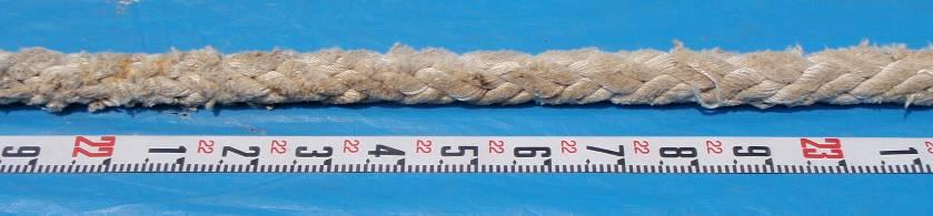
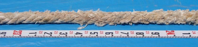
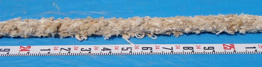

46 Photo 5: Eye-Splice of the Line Photo 6: Close-up of the Line: 20 to 26m from the end of the eye

 - 45 -")
47 Photo 7: Close-up of the Break Point (The portion from the break point toward the eye) (The portion from the break point toward the hawser drum)


48 Photo 8: Close-up of the Line: 1 to 7m off the break point toward the hawser drum
MARINE ACCIDENT INVESTIGATION REPORT
 MA2013-10 MARINE ACCIDENT INVESTIGATION REPORT October 25, 2013 Japan Transport Safety Board The objective of the investigation conducted by the Japan Transport Safety Board in accordance with the Act
MA MARINE ACCIDENT INVESTIGATION REPORT
 MA2013-4 MARINE ACCIDENT INVESTIGATION REPORT April 26, 2013 The objective of the investigation conducted by the Japan Transport Safety Board in accordance with the Act for Establishment of the Japan Transport
MA MARINE ACCIDENT INVESTIGATION REPORT
 MA2014-2 MARINE ACCIDENT INVESTIGATION REPORT February 28, 2014 The objective of the investigation conducted by the Japan Transport Safety Board in accordance with the Act for Establishment of the Japan
MARINE ACCIDENT INVESTIGATION REPORT
 MARINE ACCIDENT INVESTIGATION REPORT December 8th,2016 Adopted by the Japan Transport Safety Board Member Kuniaki Shoji Member Satoshi Kosuda Member Mina Nemoto Accident Type Contact (light buoy) Date
Unit 18 LEAVING THE DOCK
 Unit 18 LEAVING THE DOCK Basic terms - Dock Pilot - River Pilot - tug-boat - transverse thrust - effect of the screw - singling up - mooring ropes - skipper - handling of ships - buoys - dolphins - slack
05 Boat Handling. Captain
 05 Boat Handling Competence (Skills) Knowledge, Understanding and Proficiency Level Required Boat handling theory and techniques Coxswain Crew RQ RQ Describe the forces acting on a vessel while manoeuvering
Note to Shipbuilders, shipowners, ship Managers and Masters. Summary
 MARINE GUIDANCE NOTE MGN 301 (M+F) Manoeuvring Information on Board Ships Note to Shipbuilders, shipowners, ship Managers and Masters This note supersedes Marine Guidance Note MGN 201 (M+F) Summary The
MA MARINE ACCIDENT INVESTIGATION REPORT
 MA2017-9 MARINE ACCIDENT INVESTIGATION REPORT September 28, 2017 The objective of the investigation conducted by the Japan Transport Safety Board in accordance with the Act for Establishment of the Japan
MA MARINE ACCIDENT INVESTIGATION REPORT
 MA2014-1 MARINE ACCIDENT INVESTIGATION REPORT January 31, 2014 The objective of the investigation conducted by the Japan Transport Safety Board in accordance with the Act for Establishment of the Japan
MARINE ACCIDENT INVESTIGATION REPORT
 MA2011-6 MARINE ACCIDENT INVESTIGATION REPORT June 24, 2011 Japan Transport Safety Board The objective of the investigation conducted by the Japan Transport Safety Board in accordance with the Act for
Moor, Tend Mooring And Unmoor Ship - Supervisor Level -
 Marine Terminal Operations Competency Standard Moor, Tend Mooring And Unmoor Ship - Supervisor Level - Industry : Oil, Chemical and Gas Industry Competency Category : 2.0 Moor, tend mooring and unmoor
IMO ANCHORING, MOORING AND TOWING EQUIPMENT. Submitted by the Republic of Korea
 INTERNATIONAL MARITIME ORGANIZATION E IMO SUB-COMMITTEE ON SHIP DESIGN AND EQUIPMENT 48th session Agenda item 6 DE 48/6/1 17 November 2004 Original: ENGLISH ANCHORING, MOORING AND TOWING EQUIPMENT Shipboard
M/V SE CERULEAN 9V9934
 Page 1 EMERGENCY TOWING BOOKLET Volume A Table of Communicating Information (Information to be provided to a towing company) M/V SE CERULEAN 9V9934 PK 148 1 HEAVY LIFT VESSEL A Written 04.10.12 SSV 14.10.12
MARINE ACCIDENT INVESTIGATION REPORT
 MA2010-5 MARINE ACCIDENT INVESTIGATION REPORT May 28, 2010 Japan Transport Safety Board The objective of the investigation conducted by the Japan Transport Safety Board in accordance with the Act for Establishment
MA MARINE ACCIDENT INVESTIGATION REPORT
 MA2013-5 MARINE ACCIDENT INVESTIGATION REPORT May 31, 2013 The objective of the investigation conducted by the Japan Transport Safety Board in accordance with the Act for Establishment of the Japan Transport
PILOTAGE DIRECTIONS REVIEWED DECEMBER 2016
 PILOTAGE DIRECTIONS REVIEWED DECEMBER 2016 REVISION LIST Revision No. Date Details Approved by: Original All sections 12 Dec 2013 First edition of C W Brand v1.0 Pilotage Directions Revision 2 all sections
Seamanship. A braided line comprises a core of braided or stranded threads covered with a sheath. The center or core of the line gives strength.
 Seamanship 1. Describe the life boat ropes. On a life boat, we rarely use the word rope but rather lines to describe all of the ropes. Moreover, each line has a specific name, such as the painter, halyard
National Maritime Center
 National Maritime Center Providing Credentials to Mariners Q301 Rules of the Road-Inland (Sample Examination) Page 1 of 19 Choose the best answer to the following Multiple Choice Questions. NO reference
Preventing Damage to Harbour Facilities and. Ship Handling in Harbours PART 2 INDEX
 Preventing Damage to Harbour Facilities and Ship Handling in Harbours PART 2 INDEX 1 Vessel handling is based on the basic knowledge that a vessel floats in the water and returns to its original position
MA MARINE ACCIDENT INVESTIGATION REPORT
 MA2013-1 MARINE ACCIDENT INVESTIGATION REPORT January 25, 2013 The objective of the investigation conducted by the Japan Transport Safety Board in accordance with the Act for Establishment of the Japan
Incident Report. Close Quarters Pegasus II & Distraction. 26 April 2006 Class B
 Incident Report Close Quarters Pegasus II & Distraction 26 April 2006 Class B NARRATIVE Pegasus II (See Photograph 1 Pegasus II) is a 15.46 metre commercial fishing vessel with a gross tonnage of 40. She
Simplified report of safety investigation
 Simplified report of safety investigation COLLISION BETWEEN SALVATORE CAFIERO AND NAUSICAA ON 22 APRIL 2012 IN THE WESTERN APPROACHES TO THE ENGLISH CHANNEL Report published on : July 2013 2 COLLISION
GUIDELINES FOR SURVEY OF OIL FLOATING STORAGE VESSELS FIXED AT ANCHORAGE
 GUIDANCE NOTES GD03-2017 CHINA CLASSIFICATION SOCIETY GUIDELINES FOR SURVEY OF OIL FLOATING STORAGE VESSELS FIXED AT ANCHORAGE 2017 Effective from 1 March 2017 BEIJING Chapter 1 GENERAL 1.1 Application
An Investigation into the Capsizing Accident of a Pusher Tug Boat
 An Investigation into the Capsizing Accident of a Pusher Tug Boat Harukuni Taguchi, National Maritime Research Institute (NMRI) taguchi@nmri.go.jp Tomihiro Haraguchi, National Maritime Research Institute
Serenity Houseboat. Standard Operating Procedures for:
 Serenity Houseboat Standard Operating Procedures for: Docking I. Safety a. Never get between the houseboat and the dock or other larger object. b. Always wear PFDs during docking. c. Always wear snug fitting,
Donaghys Winch Ropes. Handling & Installation Guide
 Donaghys Winch Ropes Handling & Installation Guide September 2015 Choosing the right rope for the job It is important to choose the right rope for the job. Donaghys specialise in custom designing ropes
OSAKA MARTIS USER MANUAL TABLE OF CONTENTS
 OSAKA MARTIS USER MANUAL TABLE OF CONTENTS Ⅰ Ⅱ Ⅲ INTRODUCTION OPERATIONAL CONCEPT OF "Osaka MARTIS" IMPORTANT NAVIGATIONAL RULES Ⅳ COMMUNICATION 1 VHF Channels 2 Language Ⅴ PRE-ENTRY REPORT AND POSITION
SEMI FINAL EXAMINATION
 SEMI FINAL EXAMINATION 1. Which vessel may exhibit, if practicable, the lights for sailing vessels, but if she does not, she shall have ready at hand a electric torch or lighted lantern showing a white
Rules Practice Exam 9
 1 BOTH INTERNATIONAL & INLAND If your vessel is underway in fog and you hear one prolonged and three short blasts, this is a. A. vessel not under command B. sailing vessel C. vessel being towed (manned)
Report on Vessel Casualty of Accident (Form Casualty) Instructions:
 Instructions:") Report on Vessel Casualty of Accident (Form Casualty) Tuvalu Ship Registry 10 Anson Road #25-16 International Plaza Singapore 079903 Tel: (65) 6224 2345 Fax: (65) 6227 2345 Email: info@tvship.com Website:
Report on Vessel Casualty of Accident (Form Casualty) Tuvalu Ship Registry 10 Anson Road #25-16 International Plaza Singapore 079903 Tel: (65) 6224 2345 Fax: (65) 6227 2345 Email: info@tvship.com Website:
GUIDELINES FOR NAVIGATION UNDER THE CONFEDERATION BRIDGE
 (12/2009) GUIDELINES FOR NAVIGATION UNDER THE CONFEDERATION BRIDGE REVISION 1 DECEMBER 2009 Responsible Authority The Regional Director Marine Safety Atlantic Region is responsible for this document, including
Code Of Practice For Towage Operations In The Port of St Helier (Towage Guidelines)
") Code Of Practice For Towage Operations In The Port of St Helier (Towage Guidelines) This Code Covers The Use Of Tugs And Towage In The Port Of St Helier Page number Contents 2 Introduction 3 Communication
Code Of Practice For Towage Operations In The Port of St Helier (Towage Guidelines) This Code Covers The Use Of Tugs And Towage In The Port Of St Helier Page number Contents 2 Introduction 3 Communication
TECH TIPS: ROPE DEFECTS
 Hoist Ropes: Why must they be inspected? A hoist rope is not made to last forever. This is a useful fact, as the kinds of wear that appear on a rope can indicate areas of problems within an installation
MA MARINE ACCIDENT INVESTIGATION REPORT
 MA2016-10 MARINE ACCIDENT INVESTIGATION REPORT October 27, 2016 The objective of the investigation conducted by the Japan Transport Safety Board in accordance with the Act for Establishment of the Japan
properly applied assessment in the use.1 landmarks.1 approved in-service of ECDIS is not experience The primary method of fixing required for those
 STCW Code Table A-II/3 Specification of minimum standard of for officers in charge of a navigational watch and for masters on ships of less than 500 gross tonnage engaged on near-coastal voyages Ref: https://www.edumaritime.net/stcw-code
Development of TEU Type Mega Container Carrier
 Development of 8 700 TEU Type Mega Container Carrier SAKAGUCHI Katsunori : P. E. Jp, Manager, Ship & Offshore Basic Design Department, IHI Marine United Inc. TOYODA Masanobu : P. E, Jp, Ship & Offshore
MA MARINE ACCIDENT INVESTIGATION REPORT
 MA2018-2 MARINE ACCIDENT INVESTIGATION REPORT February 22, 2018 The objective of the investigation conducted by the Japan Transport Safety Board in accordance with the Act for Establishment of the Japan
Rule 8 - Action to avoid collision
 a) Any action to avoid collision shall be taken in accordance with the Rules of this Part and shall, if the circumstances of the case admit, be positive, made in ample time and with due regard to the observance
MA MARINE ACCIDENT INVESTIGATION REPORT
 MA2017-2 MARINE ACCIDENT INVESTIGATION REPORT February 23, 2017 The objective of the investigation conducted by the Japan Transport Safety Board in accordance with the Act for Establishment of the Japan
Rules Practice Exam 14
 1 BOTH INTERNATIONAL & INLAND Additional light signals are provided in the Annexes to the Rules for vessels. A. engaged in fishing B. not under command C. engaged in towing D. under sail 2 BOTH INTERNATIONAL
TECHNICAL CIRCULAR. Circular No: S-P 32/13 Revision: 1 Page: 1 of 7 Date:
 Circular No: S-P 32/13 Revision: 1 Page: 1 of 7 Date:22.05.2014 Related Requirement: UR S27 (Rev.6 June 2013) Subject: Retroactive Application for Strength Requirements for Fore Deck Fittings and Equipment
Competency Framework for Advanced Deckhand-Fishing. Competency Framework for Advanced Deckhand-Fishing
 Table of Contents (ADH-F)... 1 Function: Nautical knowledge... 1 Function Fishing Vessel Construction, Deck Equipment and Gear.... 2 Function: Fibre Ropes, Wire Ropes and Chains.... 4 Function: Knots and
Enclosure (5) to NVIC 03-16
 to NVIC 03-16") TOWING OFFICER ASSESSMENT RECORD LIMITED LOCAL AREA LOCAL LIMITED AREA (LLA) TOAR INSTRUCTIONS FOR USE The following Towing Officer Assessment Record (TOAR) is intended as a model for endorsements as Limited
TOWING OFFICER ASSESSMENT RECORD LIMITED LOCAL AREA LOCAL LIMITED AREA (LLA) TOAR INSTRUCTIONS FOR USE The following Towing Officer Assessment Record (TOAR) is intended as a model for endorsements as Limited
Rules Practice Exam 5
 1 BOTH INTERNATIONAL & INLAND Vessel "A" (towing) and vessel "B" are meeting as shown. In this situation, which statement is TRUE? Diagram 12 A. Both vessels should alter course to starboard and pass port
Deckhand Duties Questions
 Deckhand Duties Questions Ropework - Deck Gear - Moor and anchor -Lookout -Maintenance - Hygiene/safety Ropework A monkey fist is the terminal to a heaving line. Question 2 (1 Mark) Seawater acts as a
EQUIPMENT AND PERSONNEL
 1 EQUIPMENT AND PERSONNEL Inland Rivers and Gulf Coast 2013 Section 4 Topics 4.1 Equipment Boats 4.1.1 Types and Sizes of Towboats 4.1.2 Main Propulsion Equipment 4.2 Equipment Barges 4.2.1 Barge Sizes,
STRUCTURAL MEMBERS OF A SHIP. compartment stem frame beam bracket girder stern post hull angle bar stiffener
 Unit 2 SHIPS AND SHIPS TERMS STRUCTURAL MEMBERS OF A SHIP Basic terms shell plating strake keel deck tank top floor stringer buoyancy strength stability bulkhead compartment stem frame beam bracket girder
International Safety Guide Chapter 23 for Inland Navigation Tank-barges and Terminals. Chapter 23 MOORING
 Chapter 23 MOORING This Chapter deals with the preparations and procedures necessary to provide and maintain an efficient mooring arrangement whilst the tanker is berthed at a jetty. Exchange of information
National Maritime Center
 National Maritime Center Providing Credentials to Mariners (Sample Examination) Page 1 of 14 Choose the best answer to the following Multiple Choice Questions. 1. The maneuvering information required to
CORPORATE SAFETY MANUAL
 CORPORATE SAFETY MANUAL Procedure No. 32-0 Revision: Date: May 2005 Total Pages: 10 PURPOSE To provide general guidelines for the inspection of all ropes, chains, cables, slings, etc. used for personnel
National Maritime Center
 National Maritime Center Providing Credentials to Mariners (Sample Examination) Page 1 of 7 Choose the best answer to the following Multiple Choice Questions. 1. On a small boat, which knot is best suited
MA MARINE ACCIDENT INVESTIGATION REPORT
 MA2019-2 MARINE ACCIDENT INVESTIGATION REPORT February 28, 2019 The objective of the investigation conducted by the Japan Transport Safety Board in accordance with the Act for Establishment of the Japan
National Maritime Center
 National Maritime Center Providing Credentials to Mariners (Sample Examination) Page 1 of 19 Choose the best answer to the following multiple choice questions. NO reference materials are authorized for
Anchor and Anchor Cable Losses. Athens, Greece, 2 nd February 2018 Capt. Simon Rapley
 Anchor and Anchor Cable Losses Athens, Greece, 2 nd February 2018 Capt. Simon Rapley Anchor Loses Items lost: Whole anchors Anchor crowns Anchor and shackles of cable Anchor and entire anchor cable Shank
National Maritime Center
 National Maritime Center Providing Credentials to Mariners (Sample Examination) Page 1 of 16 Choose the best answer to the following Multiple Choice Questions. 1. Which term applies to the angle between
OFFSHORE PATROL VESSEL OPERATIONS
 Florida Fish and Wildlife Conservation Commission Division of Law Enforcement OFFSHORE PTROL VESSEL OPERTIONS GENERL ORDER EFFECTIVE DTE RESCINDS/MENDS PPLICBILITY 30 May 7, 2018 July 21, 2008 ll Sworn
NavRule Practice Exam, 70 Series Practice April 24, Labeled F (I received a reply from the testing service that all these answers were
 1. INTERNATIONAL & INLAND An all-round flashing yellow light may be exhibited by a(n)? a. vessel laying cable b. vessel towing a submerged object c. vessel not under command d. air cushion vessel 2. INTERNATIONAL
TOWING OFFICER ASSESSMENT RECORD
 TOWING OFFICER ASSESSMENT RECORD NEAR COASTAL / OCEANS SIGNATED EXAMINER INFORMATION All Designated Examiners (s) signing off successful completion of practical assessments should provide the information
OPERATIONS SEAFARER CERTIFICATION GUIDANCE NOTE SA MARITIME QUALIFICATIONS CODE
 Page 1 of 8 Compiled by Chief Examiner Approved by Qualifications Committee: 27 September 2013 OPERATIONS SEAFARER CERTIFICATION GUIDANCE NOTE SA MARITIME QUALIFICATIONS CODE Page 2 of 8 KNOWLEDGE, UNDERSTANDING
AI AIRCRAFT SERIOUS INCIDENT INVESTIGATION REPORT AERO ASAHI CORPORATION J A
 AI2017-3 AIRCRAFT SERIOUS INCIDENT INVESTIGATION REPORT AERO ASAHI CORPORATION J A 9 6 7 8 July 27, 2017 The objective of the investigation conducted by the Japan Transport Safety Board in accordance with
CERTIFICATE OF SURVEY AND OPERATION Marine Safety (Domestic Commercial Vessel) National Law Act 2012, Schedule 1
 National Law Act 2012, Schedule 1") CERTIFICATE OF SURVEY AND OPERATION Marine Safety (Domestic Commercial Vessel) National Law Act 2012, Schedule 1 Marine Order 503 (Certificates of Survey - national law) Marine Order 504 (Certificates
CERTIFICATE OF SURVEY AND OPERATION Marine Safety (Domestic Commercial Vessel) National Law Act 2012, Schedule 1 Marine Order 503 (Certificates of Survey - national law) Marine Order 504 (Certificates
NAVIGATION AND SEAMANSHIP Secure vessel at mooring, anchor, and berth
 1 of 5 level: 3 credit: 4 planned review date: December 2005 sub-field: purpose: entry information: accreditation option: moderation option: Maritime People credited with this unit standard are able to:
MANAGEMENT SYSTEM MANUAL
 1. Purpose The purpose of this procedure is to establish routine check-off lists to be used in preparation for arrival and departure aboard the R/V Oceanus. 2. Responsibility The Master is responsible
ITTC Recommended Procedures and Guidelines
 Page 1 of 10 Table of Contents Speed/Power Trials... 2 1. PURPOSE... 2 2. DEFINITIONS... 2 3. RESPONSIBILITIES... 3 3.1 Shipbuilders Responsibilities... 3 3.2 The Trial Team... 4 4. PROCEDURES... 4 4.1
Towing Officers' Assessment Record: Near Coastal/Oceans
 Towing Officers' Assessment Record: Near Coastal/Oceans NAME: LICENSE NO.: Task No. Considered Proficient Common Element Task or Duty DE's Initials Date A. Vessel Familiarization A.1. X Locate and demonstrate
National Maritime Center
 National Maritime Center Providing Credentials to Mariners (Sample Examination) Page 1 of 7 Choose the best answer to the following Multiple Choice Questions. 1. Which is usually the most gentle way of
APPLICATION FOR PILOT EXEMPTION CERTIFICATE (PEC)
") APPLICATION FOR PILOT EXEMPTION CERTIFICATE (PEC) according to the Swedish Transport Agency s Regulations and General Advice (TSFS 2017:88) on Pilotage New application Renewal of PEC No: Supplement to
APPLICATION FOR PILOT EXEMPTION CERTIFICATE (PEC) according to the Swedish Transport Agency s Regulations and General Advice (TSFS 2017:88) on Pilotage New application Renewal of PEC No: Supplement to
Injury during mooring operation
 July 2016 Injury during mooring operation It was early morning and the vessel was approaching the port. There was no wind or currents. On the stern was an AB preparing the mooring ropes. The stern lines
A STUDY ON FACTORS RELATED TO THE CAPSIZING ACCIDENT OF A FISHING VESSEL RYUHO MARU No.5
 8 th International Conference on 49 A STUDY ON FACTORS RELATED TO THE CAPSIZING ACCIDENT OF A FISHING VESSEL RYUHO MARU No.5 Harukuni Taguchi, Shigesuke Ishida, Iwao Watanabe, Hiroshi Sawada, Masaru Tsujimoto,
MA MARINE ACCIDENT INVESTIGATION REPORT
 MA2017-11 MARINE ACCIDENT INVESTIGATION REPORT Novemb 30, 2017 The objective of the investigation conducted by the Japan Transport Safety Board in accordance with the Act for Establishment of the Japan
INTERNATIONAL NAVAL SHIPS 2018
 GUIDE FOR BUILDING AND CLASSING INTERNATIONAL NAVAL SHIPS 2018 NOTICE NO. 3 July 2018 The following Rule Changes were approved by the ABS Rules Committee on 1 June 2018 and become EFFECTIVE AS OF 1 JULY
1. An aid to navigation is any object external to the boat that: 1) helps a boater pilot a boat safely, 2) aids a boater in finding position and 3)
 helps a boater pilot a boat safely, 2) aids a boater in finding position and 3)") 1. An aid to navigation is any object external to the boat that: 1) helps a boater pilot a boat safely, 2) aids a boater in finding position and 3) a. marks the best fishing holes. b. provides a place
1. An aid to navigation is any object external to the boat that: 1) helps a boater pilot a boat safely, 2) aids a boater in finding position and 3) a. marks the best fishing holes. b. provides a place
Abrasion and Twist Effects on High-Performance Synthetic Ropes for Towing Applications
 Abrasion and Twist Effects on High-Performance Synthetic Ropes for Towing Applications Kris Volpenhein, Application Engineer Rafael Chou, Vice President of Research and Development Samson Rope Technologies,
References: Manual Chapt. 9 ISO 9001 par.7 ISO par. 4 ISM Code par. 7; 8
 SQEMS OPERATING PROCEDURE OP-SAF-03 1 of 5 References: Manual Chapt. 9 ISO 9001 par.7 ISO 14001 par. 4 ISM Code par. 7; 8 1. SCOPE This Procedure establishes criteria for the control and management of
Accident Report. Failure of No. 2 Crane Tasman Mariner. 20 September 2005 Class B
 Accident Report Failure of No. 2 Crane Tasman Mariner 20 September 2005 Class B REPORT NO.: 05 3847 TASMAN MARINER CRANE FAILURE On 20 September 2005, Tasman Mariner was moored port side to No. 6 berth,
BLUE DAWN 1959 SCHIPSWERT General Description: SCHIPSWERT M / M / 31 3 Cummins Lebanese 5 / 12
 General Description: BUILDER: YEAR BUILT: L.O.A (m/ft).: BEAM (m/ft).: MAIN ENGINES: CRUISING SPEED (kn): MAX. SPEED (kn): FLAG: CABINS / GUESTS: SCHIPSWERT 1959 62.05M / 203 7 9.50M / 31 3 Cummins 10
NavRule Practice Exam, 70 Series Practice April 18, Labeled C have been copied to collection
 1C. INTERNATIONAL & INLAND There are two classes of vessel which, to the extent necessary to carry out their work, do not have to comply with the rule regarding traffic separation schemes. One of these
MANOEUVRING BOOKLET V1.06
 MANOEUVRING BOOKLET V1.6 Mathematical model of Integrated Tug Barge 45 Version: v9 Dll Version: 2.31.558 According to: Solas II-1, regulation 28.3 St. Petersburg 26 1. GENERAL DESCRIPTION 1.1. Ships particulars
ARM 6.4 R/V ARMSTRONG SMALL BOAT OPERATIONS
 1. Purpose The purpose of this procedure is to set forth the standards for small boat operations and the qualifications for a small boat operator. These guidelines shall be used while operating the small
WHAT IS IMPACT OF PANAMA CANAL WIDENING?
 WHAT IS IMPACT OF PANAMA CANAL WIDENING? Introduction One hundred years ago, in 1914, the Panama canal was opened. At the time it was the biggest American engineering project. Ever since it has played
Technical Bulletin. Rope Inspection and Retirement
 There are basically three steps to consider in providing the longest possible service life, the safest conditions and long range economy for ropes: Selection, Usage and Retirement. The use of rope for
Class B Accident Report. Tokerau & Kawau Kat Collision
 Class B Accident Report Tokerau & Kawau Kat Collision At Auckland on 11 December 2004 REPORT NO: 04 3624 TOKERAU& KAWAU KAT COLLISION Whilst departing from the ferry terminal in Auckland, Tokerau collided
Mooring, rafting, springing, locks etc, etc
 Mooring, rafting, springing, locks etc, etc www.skysailtraining.co.uk Mooring Alongside a pontoon 1. Adequate fenders 2. Springs are as important as shore lines they stop the boat moving fore and aft.
LESSONS LEARNED FROM MARINE CASUALTIES. Very serious marine casualty: tug master struck by a falling stores container
 LESSONS LEARNED FROM MARINE CASUALTIES 1 FATALITY Very serious marine casualty: tug master struck by a falling stores container While discharging a routine parcel of crude oil alongside an oil terminal,
National Maritime Center
 National Maritime Center Providing Credentials to Mariners U.S.C.G. Merchant Marine Exam (Sample Examination) Page 1 of 22 U.S.C.G. Merchant Marine Exam: Illustrations: 10 Choose the best answer to the
SINGLE BRAID INSPECTION
 INSPECTION PROTRUDING STRAND Often, a strand will get snagged or pulled out from the rest of the rope. As long as the strand isn t broken, this is a repairable issue. Protruding strands are generally caused
MA MARINE ACCIDENT INVESTIGATION REPORT
 MA2015-3 MARINE ACCIDENT INVESTIGATION REPORT February 26, 2015 The objective of the investigation conducted by the Japan Transport Safety Board in accordance with the Act for Establishment of the Japan
Uncontrolled document if printed.
 APPENDIX 3 APPRENTICE PILOT S TRAINING SYLLABUS Issue Date: 16 th March, 2010 Date of Revision: 22nd May, 2013 Revision #2 i THE PURPOSE OF THIS SYLLABUS The purpose of this training syllabus is to ensure
You must stop your. pass with caution on the port side of vessel "B" The vessel moving upstream against the current
 BK NUM ANS QUESTION ANSWER A ANSWER B ANSWER C ANSWER D ILLUST 1 1 C 1 2 B INLAND ONLY You are navigating in a narrow channel and must remain in the channel for safe operation. Another vessel is crossing
National Maritime Center
 National Maritime Center Providing Credentials to Mariners (Sample Examination) Page 1 of 14 Choose the best answer to the following Multiple Choice Questions. 1. The maneuvering information required to
"RIGGING SAFETY IN CONSTRUCTION ENVIRONMENTS"
 PRESENTER'S GUIDE "RIGGING SAFETY IN CONSTRUCTION ENVIRONMENTS" Part of the "CONSTRUCTION SAFETY KIT" Series Quality Safety and Health Products, for Today...and Tomorrow OUTLINE OF MAJOR PROGRAM POINTS
ANY OTHER BUSINESS. Guidelines for passenger ship tender operator. Submitted by Cruise Lines International Association (CLIA) SUMMARY
 SUMMARY") E SUB-COMMITTEE ON STANDARDS OF TRAINING AND WATCHKEEPING 42nd session Agenda item 3 STW 42/13/2 25 October 2010 Original: ENGLISH ANY OTHER BUSINESS Guidelines for passenger ship tender operator Submitted
E SUB-COMMITTEE ON STANDARDS OF TRAINING AND WATCHKEEPING 42nd session Agenda item 3 STW 42/13/2 25 October 2010 Original: ENGLISH ANY OTHER BUSINESS Guidelines for passenger ship tender operator Submitted
Rules Practice Exam 11
 1 BOTH INTERNATIONAL & INLAND While underway in fog, you hear a vessel sound one prolonged blast followed by two short blasts on the whistle. What does this signal indicate? A. A vessel towing B. A vessel
ST. VINCENT AND THE GRENADINES
 ST. VINCENT AND THE GRENADINES MARITIME ADMINISTRATION CIRCULAR N SOL 036 Amendment to SOLAS 1974 as amended, Resolution MSC.256 (84) TO: SHIPOWNERS & SHIPS OPERATORS & MANAGERS, MASTERS SURVEYORS TO FLAG
MANOEUVRING BOOKLET V1.06
 MANOEUVRING BOOKLET V.6 Mathematical model of VLCC (Dis.769t) bl. Version: v Dll Version:.3.558 According : Solas II-, regulation 8.3 St. Petersburg 6 . GENERAL DESCRIPTION.. Ships particulars... Ships
SS&S Chapter 8 Instructor Guide
 SS&S Chapter 8 Instructor Guide The Rules of the Nautical Road The PowerPoints (PPT) slides for this SS&S chapter were copied from the BS&S-13 th Ed PPT because they are identical. Only the chapter numbers
Rules Practice Exam 7
 1 INTERNATIONAL ONLY The light which may be used with a vessel's whistle is to be. A. used when the whistle is broken B. used prior to sounding the whistle C. used only at night D. a white light 2 INTERNATIONAL
NAUTICAL TERMINOLOGY
 It s important to have a basic understanding of common nautical terms associated with the parts, positions and directions of your vessel. Knowing these terms will make it easier to communicate with people
AUTORIDAD DEL CANAL DE PANAMÁ EXECUTIVE VICE PRESIDENCY FOR OPERATIONS
 3654-A (OPXI v. 3-2-2011 AUTORIDAD DEL CANAL DE PANAMÁ EXECUTIVE VICE PRESIDENCY FOR OPERATIONS ADVISORY TO SHIPPING No. A-20-2013 August 2, 2013 TO : All Shipping Agents, Owners, and Operators SUBJECT:
 7 The Guidelines of Measures for preventing Typhoon Disaster ( Objective ) Article1 The objective of this guideline is to establish steps necessary to implement the measures for preventing typhoon