MERCHANT SHIP STABILITY
|
|
|
- Ethel O’Brien’
- 5 years ago
- Views:
Transcription

1 MERCHANT SHIP STABILITY (METRIC EDITION) A Companion to "Merchant Ship Construction" BY H. J. PURSEY EXTRA MASTER Formerly Lecturer to the School of Navigation University of Southampton GLASGOW BROWN, SON & FERGUSON, LTD., NAUTICAL PUBLISHERS 4-10 DARNLEY STREET
2 Copyright in all countries signatory to the Berne Convention All rights reserved First Edition 1945 Sixth Edition Revised 1983 Reprinted Reprinted 1996 ISBN ISBN (Revised Sixth Edition) (Sixth Edition) 1996-BROWN, SON & FERGUSON, LTD., GLASGOW, G41 2SD Printed and Made in Great Britain
3 INTRODUCTION DURING the past few years there have been considerable changes in the approach to ship stability, so far as it affects the merchant seaman. The most obvious of these is the introduction of metric units. In addition, the Department of Trade have already increased their examination requirements: they have also produced recommendations for a standard method of presenting and using stability information, which will undoubtedly be reflected in the various examinations. This revised edition has been designed to meet the above-mentioned requirements. The basic information contained in the early chapters has been retained for the benefit of those who are not familiar with such matters. The remainder of the text has been re-arranged and expanded, as desirable, to lead into the new material which has been introduced; whilst a new chapter on stability information has been added to illustrate the Department of Trade recommendations. The theory of stability has been covered up to the standard required for a Master's Certificate and includes all that is needed by students for Ordinary National Diplomas and similar courses. This has been carefully linked-up with practice, since the connection between the two is a common stumbling block. Particular attention has been paid to matters which are commonly misunderstood, or not fully appreciated by seamen. SOUTHAMPTON, H. J. P. V
4 CONTENTS CHAPTER I-SOME GENERAL INFORMATION PAGE The Metric System Increase of pressure with depth Effect of water in sounding pipes The Law of Archimedes Floating bodies and the density of water... 4 Ship dimensions. 4 Decks Ship tonnages 4 Grain and bale measurement 5 Displacement and deadweight 5 Draft Freeboard 6 Loadlines 6 CHAPTER 2-AREAS AND VOLUMES Areas of plane figures 8 Surface areas and volumes 8 Areas of waterplanes and other ship sections 9 Simpson's First Rule. 10 Simpson's Second Rule 12 The 'Five-Eight Rule' 12 Sharp-ended waterplanes 13 Unsuitable numbers of ordinates 13 Volumes of ship shapes 15 Half-intervals 16 Coefficients of fineness 17 Wetted surface 18 CHAPTER 3-FORCES AND MOMENTS Forces 19 Moments 20 Centre of gravity 23 Effect of weights on centre of gravity. 25 Use of moments to find centre of gravity 27 To find the centre of gravity of a waterplane 28 To find the centre of buoyancy of a ship shape 30 The use of intermediate ordinates 31 Appendages.. 32 Inertia and moment of inertia 33 Equilibrium.. 36 CHAPTER 4-DENSITY, DEADWEIGHT AND DRAFT Effect of density on draft Tonnes per centimetre immersion Loading to a given loadline Vll
5 VIl1 CONTENTS CHAPTER 5-CENTRE OF GRAVITY OF SHIPS PAGE Centre of Gravity of a ship-g KG Shift of G KG for any condition of loading Deadweight moment Real and virtual centres of gravity. 46 Effect of tanks on G CHAPTER 6-CENTRES OF BUOYANCY AND FLOTATION Centre of buoyancy-b Centre of flotation-f 49 Shift of B CHAPTER 7-THE RIGHTING LEVER AND METACENTRE Equilibrium of ships The righting lever-gz The metacentre-m Metacentric height-gm Stable, unstable and neutral equilibrium Longitudinal metacentric height-gm L CHAPTER 8-TRANSVERSE STATICAL STABILITY Moment of statical stability Relation between GM and GZ.. 57 Initial stability and range of stability. 57 Calculation of a ship's stability. 58 Calculation of BM The Inclining Experiment Statical stability at small angles of heel 62 Statical stability at any angle of heel 62 GZ by the Wall-Sided Formula. 64 Loll, or list Heel due to G being out of the centre-line. 65 Loll due to a negative GM CHAPTER 9-FREE SURFACE EFFECT The effect of free surface of liquids Free surface effect when tanks are filled or emptied 72 Free surface in divided tanks. 73 Free surface moments CHAPTER 10-TRANSVERSE STATICAL STABILITY IN PRACTICE Factors affecting statical stability Placing of weights. 78 Stiff and tender ships 78 Unstable ships. 80 Ships in ballast The effect of winging out weights.. 82 Deck cargoes Free liquid in tanks Free surface effect in oil tankers 85
6 CONTENTS IX. CHAPTER 11-DYNAMICAL STABILITY PAGE Dynamical stability Dynamical stability from a curve of statical stability 86 Calculation of dynamical stability 88 CHAPTER 12-LONGITUDINAL STABILITY Longitudinal metacentric height-gm L. 90 Calculation of EM L 91 Trim Change of mean draft due to change of trim 94- Displacement out of designed trim. 96 Moment to change trim by one centimetre 98 The effect of shifting a weight 99 Effect of adding weight at the centre of flotation 101 Moderate weights loaded off the centre of flotation 103 Large weights loaded off the centre of flotation 106 To obtain special trim or draft 108 Use of moments about the after perpendicular CHAPTER 13-ST ABILITY CURVES AND SCALES Hydrostatic curves 117 The deadweight scale 118 Hydrostatic particulars 118 Curves of statical stability 119 Cross curves Effect of height of G 122 KN curves The Metacentric Diagram 123 CHAPTER 14-BILGING OF COMPARTMENTS The effect of bilging a compartment Permeability Bilging an empty compartment amidships 127 Bilging an amidships compartment, with cargo 128 Bilging an empty compartment, not amidships 129 Effect of a watertight flat 131 CHAPTER IS-STABILITY AND THE LOAD LINE RULES Stability requirements Information to be supplied to ships The Stability Information Booklet 134 The use of maximum deadweight moments Simplified stability information 140 CHAPTER 16-MISCELLANEOUS MATTERS Drydocking and grounding 143 The effect of density on stability. 145 The effect of density on draft of ships 146 Derivation of the fresh-water allowance 147 Reserve buoyancy Longitudinal bulkheads 147 Bulkhead subdivision and sheer 148 Pressure on bulkheads.. 149
7 x CONTENTS CHAPTER 17-ROLLING PAG The formation of waves 150 The Trochoidal Theory 150 The period of waves 150 The period of a ship 151 Synchronism Unresisted rolling 152 Resistances to rolling 152 The effects of bi1ge keels 153 Cures for heavy rolling 153 CHAPTER 18-SUMMARY Abbreviations 154 Formu!ae 156 Definitions 161 Prob]ems 164 DEADWEIGHT SCALE, HYDROSTATIC PARTICULARS AND HYDROSTATIC CURVES Insert at end of book
8
9
10
11 Ship Dimensions.-The following are the principal dimensions used in measuring ships. LIoyds' Length is the length of the ship, measured from the fore side of the stem to the after side of the stern post at the summer load-line. In ships with cruiser sterns, it is taken as 96 per cent of the length overall provided that this is not less than the above. Moulded Breadth is the greatest breadth of the ship, measured from side to side outside the frames, but inside the shell plating. Moulded Depth is measured vertically at the middle length of the ship, from the top of the keel to the top of the beams at the side of the uppermost continuous deck. The Framing Depth is measured vertically from the top of the double bottom to the top of the beams at the side of the lowest deck. Depth of Hold is measured at the centre line, from the top of the beams at the tonnage deck to the top of the double bottom or ceiling. Decks.-The Freeboard Deck is the uppermost complete deck, having permanent means of closing all openings in its weather portion. The Tonnage Deck is the upper deck in single-decked ships and the second deck in all others. Ship Tonnages.- These are not measures of weight, but of space: the word "ton" being used to indicate 100 cubic feet or 2 83 cubic metres. For instance, if the gross tonnage of a ship is 5000 tons this does not mean that she weighs that amount, but that certain spaces in her measure 500,000 cubic feet or cubic metres.
12 SOME GENERAL INFORMATION 5 Under Deck Tonnage is the volume of the ship below the tonnage deck. It does not normally include the cellular double bottom below the inner bottom: or, in the case of open floors, the space between the outer bottom and the tops. of the floors. Gross Tonnage is under deck tonnage, plus spaces in the hull above the tonnage deck. It also includes permanently enclosed superstructures, with some exceptions, and any deck cargo that is on board. Nett Tonnage is found by deducting, from the gross tonnage, certain non-earning spaces. These "deductions" inc1ude crew accommodation, stores and certain water ballast spaces: also an "allowance for propelling power" which depends partly on the size of the machinery spaces. Under the 1967 Tonnage Rules, some ships may now have a Modified Tonnage. This means that they have a tonnage which is less than the normal tonnage for a ship of their size, but are not allowed to load so deeply. Other ships may have two Alternative Tonnages: normal tonnage for use when they are loaded to their normal loadlines; or a modified tonnage when they are loaded less deeply. Such ships are marked with a special "Tonnage Mark" to indicate which tonnage is to be used. Grain and Bale Measurement.- These terms are often found on the plans of ships and refer to the volume of the holds, etc. Grain Measurement is the space in a compartment taken right out to the ship's side. In other words, it is the amount of space which would be available for a bulk cargo such as grain. Bale Measurement is the space in a compartment measured to the inside of the spar ceiling, or, if this is not fitted, to the inside of the frames. It is the space which would be available for bales and similar cargoes. Displacement.-Is the actual weight of the ship and all aboard her at any particular time. Since a floating body displaces its own weight of water, this means that displacement is equal to the weight of water displaced by the ship. Light Displacement is that of the ship when she is at her designed light draft. It consists of the weight of the hull, machinery, spare parts and water in the boilers. Loaded Displacement is that of a ship when she is floating at her summer draft. Deadweight.-This is the weight of cargo, stores, bunkers, etc., on board a ship. In other words, it is the difference between the light displacement and the displacement at any particular draft. When We say that a ship is of so many tonnes deadweight, we usually mean that the difference between her light and loaded displacements is so many tonnes.
13 {) MERCHANT SHIP STABILITY Draft.-This is the depth of the bottom of the ship's keel below the -surface of the water. It is measured forward and aft at the ends of the ship. When the drafts at each end are the same, the ship is said to be on an even keel. When they differ, the ship is said to be trimmed by the head, or by the -stem, according to which is the greater of the two drafts. Mean Draft is the mean of the drafts forward and aft. Freeboard.-Statutory Freeboard is the distance from the deck-line to the centre of the plimsoll mark. The term "Freeboard" is often taken to mean the distance from the deck-line to the water. Ordinary Load-lines.-The load-lines and deck line must be painted in white or yellow on a dark background, or in black on a light background. The deck-line is placed amidships and is 300 millimetres long and 25 millimetres wide. Its upper edge marks the level at which the top of the freeboard deck, if continued outward, would cut the outside of the shell plating.
14
15
16
17
18
19
20
21
22
23
24
25
26
27
28
29
30
31
32
33
34
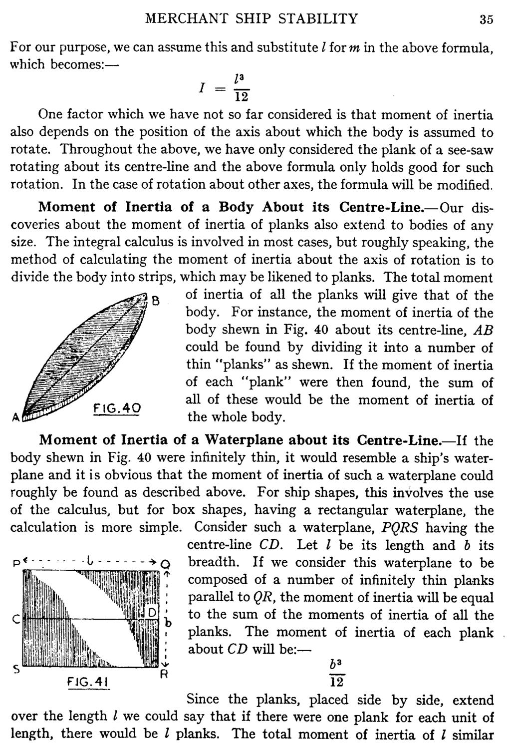
35
36
37 30 MERCHANT SHIP STABILITY To Find the Centre of Buoyancy of a Ship Shape.- In Chapter 2 it has been shewn how we can obtain the volume of a ship sha pe, by putting cross-sectional areas through Simpson's Rules as if they were ordinates. Similarly, if we put cross-sectional areas through the process described in the last section, we can obtain the position of the centre of gravity of a homogeneous ship shape. The centre of gravity of a ship's underwater vo lume is the centre of buoyancy. So if we take a series of equally-spaced sections for the ship's underwater volume and put them through the Rules, we shall obtain the fore and aft position of the centre of buoyancy. Similarly, a series of equally-spaced waterplanes, put through the Rules will give the vertical position of the centre of buoyancy. ExamPle.-A ship's underwater volume is divided into the following vertical cross-sections, from forward to aft, spaced 20 metres apart: 10; 91; 164; 228; 265; 292; 273; 240; 185; Ill; 67 square metres. If the same underwater volume is divided into waterplanes, 2 metres apart, their areas, from the keel upwards are: 300; 2704; 3110; 3388; 3597; 3759; 3872 square metres. Find the position of the centre of buoyancy (a) fore and aft, relative to the midordinate. (b) vertically. above the keel.
38
39
40 The effect of an appendage on the centre of gravity of a homogeneous ship shape can be calculated in the same way. Inertia.-A stationary body resists any attempt to move it and a moving body any attempt to change its speed or direction. This property is called "inertia" and a certain amount of force must be exerted to overcome it. If we consider what would happen if we tried to play football with a cannon bau, it should be obvious that the greater the weight of the body, the greater will be its inertia. Thus, the weight of a body gives a measure of its inertia so far as ordinary non-rotational motion is concerned. For the sake of correctness, we shall, from now on, use the word "mass" instead of "weight", but for our present purpose we may take it to mean the same thing. Moment of Inertia and Radius of Gyration.-It has been shewn earlier in this chapter that in ordinary motion, the behaviour of a body depends on the amounts of the forces applied to it: but that where a turning, or rotational movement is attempted, the behaviour of the body depends on the trtoments of the forces applied. In a somewhat similar way, although the inertia of ordinary motion is governed by mass, the inertia of rotational motion is governed by a quantity called its "moment of inertia", or "second moment". There is this difference, however, that both inertia and moment of inertia are independent of the forces applied to the body. Roughly speaking we may say that in the case of ordinary motion, the greater the mass, or inertia, the greater the resistance of the body to being moved; in the case of rotational
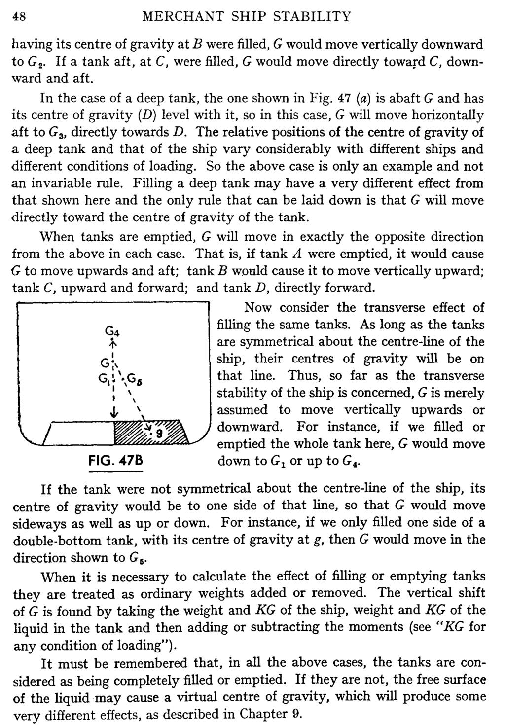
41
42
43
44 CHAPTER 4 DENSITY, DEADWEIGHT AND DRAFT We have already seen that the volume displaced by a floating body varies inversely as the density of the water in which it floats. This means that if a ship's displacement remains the same, her draft will increase if she enters water of less density; or will decrease if she enters water of greater density. We also know that a ship which loads cargo (i.e. increases her deadweight) will increase her draft, whilst a ship which discharges cargo will decrease her draft, if the density of the water does not change. The Effect of Density on Draft of Box Shapes.-In the case of box shapes, the volume displaced is equal to the product of length, breadth and draft; so we can say:- Effect of Density on Draft of Ship Shapes.-These also increase their draft when the density of the water decreases and vice versa, but in this case the change is not in proportion and its calculation is more complicated. We overcome this difficulty by giving each ship a "Fresh Water Allowance" when her load-lines are assigned. This allowance is approximately the amount by which the ship will decrease her draft on going from fresh water to salt water. The ordinary load-lines show the draft at which a ship can safely remain at sea. In the smooth water of a harbour or river, it would be quite safe to load her a little below these marks, provided that she rises to them when or before she reaches the open sea. A ship loading in a harbour of fresh water could submerge her load lines by the amount of her fresh-water allowance, since she would rise to her proper load line on reaching salt water. 37
45
46
47 Loading to a Given Loadline.-To find out how much to load in order to float at a given loadline on reaching salt water:- (a) Find the ship's present mean draft or freeboard. If she has a list, the freeboards on the Port and Starboard sides will be different: if so, take the mean of the two. (b) Calculate the dock water allowance and apply this to the required salt water draft or freeboard. This will give the allowable draft or freeboard to which the ship can be loaded in the dock water. (c) The difference between (a) and (b), above, will be the allowable sinkage in the dock water. (d) Adjust the T.P.C. for the density of the dock water. (e) The allowable sinkage, multiplied by the adjusted T.P.C. will be the amount to load to bring the ship to her appropriate load line on reaching salt water. (/) If the ship will use fuel, stores, etc., after leaving her berth, but before reaching salt water, this will reduce her draft to less than that allowable. To compensate for this, extra cargo, equal to the weight of fuel and stores so used, may be loaded before sailing. Example I.-A ship is loading in an upriver port, where the density of the water is tjm 3 Her present freeboards are 1832 mm on the Port side and 1978mm on the Starboard side. Her statutory summer freeboard is 1856 mm; Fresh water allowance is 148 mm; and her T.P.C. is t. On the voyage downriver, she is expected to use 24 tonnes of fuel and 5 tonnes of stores and fresh water. Find how much more cargo she can load to be at her summer load line in salt water.
48
49 CHAPTER 5 CENTRE OF GRAVITY OF SHIPS Centre of Gravity of a Ship-' 'G ".- This is often defined as the point through which all the weight of the ship is considered to act vertically down~ wards. A ship may be regarded as a hollow shell, inside which weights may be added, removed, or shifted about. Thus, the position of the centre of gravity will change with every condition of loading and must be calculated each time that the ship's stability is to be found. The transverse and longitudinal positions are always considered separately, as in the case of any other body (see Chapter 3). As far as the transverse position is concerned, G is usually assumed to be on the centre-line; since if it were not so the ship would list. Longitudinally, it may be forward of, or abaft amidships and is considered accordingly. "KG".-The vertical height of the centre of gravity above the keel is usually called "KG". This is due to the fact that, in stability diagrams, K is usually taken to denote the keel and G the centre of gravity. "Li~ht KG."-The height of G above the keel in the light ship, before any cargo, stores or fuel are placed on board, is calculated by Naval Architects. It is given to the seaman in the ship's stability information. Before a ship is built, the KG is estimated, usually by comparison with some existing ship of similar size and lines, although in some unusual cases it is actually calculated approximately. The KG of the completed ship, when light, can be found by means of the "Inclining Experiment", which will be described later. Shift of "G".-The centre of gravity of a ship obeys the same laws as that of any other body. Let us summarise the conclusions which we drew in Chapter 3 with regard to this matter. G moves directly towards the centre of gravity of any weight added to the ship, directly away from the centre of gravity of any weight taken away from the ship and parallel to the shift of the centre of gravity of any weight moved from one place to another. 42
50
51 44 MERCHANT SHIP STABILITY the KG for any other condition of loading, so he must find this for himself if he requires it. When weights are added to the ship, G will move upwards or downwards according to whether the centre of gravity of the weight is above or below that of the ship. (Note.that we are here only considering the shift of G in the vertical direction.) In this case, we could use the method just described to find successive shifts of G due to each weight: but this would be laborious and errors could easily creep into the calculations. A better and more simple method of finding the new KG is to take moments about a horizontal line through the keel, known as the "base line". Now, moment is weight multiplied by length of lever. In this case, the length of lever will be the distance from the base line to the centre of gravity of the weight (sometimes written as Kg). So the moment of each weight = w x Kg And final KG = Total moment -:--total weight. The method now becomes:- (a) The ship's original displacement and KG are multiplied together to give her original moment. (b) Each weight, added or removed, is multiplied by its height above the base line, to give its moment. Added weights and moments are added to those of the ship. \Veights removed and their moments are subtracted. (c) The total moment, divided by the total weight, will give the new KG of the ship. ExamPle I.-A ship arrives in port with a displacement of 4250 tonnes and KG of 5,96 metres. She then loads 520 tonnes at 6 3 m above the keel; 1250 tonnes at 4 2. m above the keel; 810 tonnes at 11 6 m above the keel. She also discharges 605 tonnes from 2 4 m above the keel. What will then be her KG?
52
53
54
55
56
57 50 MERCHANT SHIP STABILITY when heeled must be the same as that which she displaced when upright; so that the volumes of the immersed wedge and of the emerged wedge must be equal. When the sides of the ship are parallel, the line forming the apex of each wedge must divide each waterplane into exactly equal areas. For instance, in the figure, the line EF must be such that the area SNEF is equal to the area TMEF and the area SlQEF is equal to the area T1PEF. This will hold good whether the ship swings longitudinally or transversely, or, for that matter, in any direction. It is obvious that all such "centre-lines" must cut each other at one point-the geometrical centre of each waterplane; or, in other words, its centre of gravity. In box-shaped ships, the centres of gravity of the upright and heeled waterplanes must coincide, unless the deck-edge becomes submerged, or the bilge emerges from the water. In the case of ship-shapes this is not strictly true, but for small angles of heel or trim it can be taken as correct for all practical purposes. This gives us a new definition for the centre of flotation, namely that the centre of flotation is the centre of gravity of a ship's waterplane. The transverse position of the centre of flotation is always at the centre line of the waterplane; that is, the intersection of the waterplane and the centreline of the ship. Longitudinally, it is in the waterplane and at the centre-line for box shapes; but may be a little abaft or forward of the centre-line in ship shapes. Chapter 3 shews how it may be found. Shift of "B".-The centre of buoyancy has been defined as the centre of gravity of the water which has been displaced by a ship. It may, therefore, be expected to obey the same laws as any other centre of gravity. Fig. 49
58
59
60 CHAPTER 7 THE RIGHTING LEVER AND METACENTRE Equilibrium of Ships.-We have seen in Chapter 3 that a body's state of equilibrium determines whether, when it is tilted, it will right itself, remain as it is, or turn over. Seamen are, naturally; very much concerned as to whether their ships will remain upright and so the study of equilibrium forms an important part of ship stability. In the normal ship, the centre of gravity is always higher than the centre of buoyancy; that is, KG is greater than KB. The force of gravity acts vertically downwards through the former and the force of buoyancy vertically upwards through the latter. As we have already seen, these two forces must be equal. It has been shewn in Chapter 3 that the equilibrium of a tilted body depends on the relative positions of the centre of gravity and the point of support. Unless one is vertically over the other, the body will try to turn in one direction or the other. This will hold good for ships, if we substitute "centre of buoyancy" for "point of support"; thus for a ship to remain at rest, G must be vertically over B.
61
62
63
64
65 58 MERCHANT SHIP STABILITY A ship's initial stability does not necessarily indicate what her range vf stability is likely to be, or vice versa. The two have little to connect them and a ship with a large intial stability may have either a large or small range of stability. It is also quite possible for a ship to have negative initial stability, yet to become stable at a small angle of heel and thereafter to be able to heel to quite a large angle before she capsizes, Calculation of a Ship '8 Stability,-When a ship is built, the naval architects calculate her displacement, deadweight and the height of the centre of buoyancy above the keel (KB). They also find the distance of the metacentre above the centre of buoyancy (BM) and, by adding this to the KB, obta.in the height of the metacentre (KM). Once the ship is nearly completed, the "Inclining Experiment" is performed to find the metacentric height (GM) of the ship in the light condition, This is subtracted from the light KM to give the height of the centre of gravity above the keel (the light KG). The above information is tabulated in the "Deadweight Scale", or given in the form of graphs called "Curves of Stability", The righting levers for various angles of heel and for assumed KG's are also calculated and added to the stability ii'formation; usually in the form of "Cross Curves", Care is taken to see that the range of stability is adequate to ensure the safety of the ship at any reasonable angle of heel if she is properly loaded. This completes the naval architects' part of the work. Armed with the above information, the seaman can calculate the KG of his ship at any stage of loading, and can thus find her KM and GM, her righting levers at various angles of heel and her approximate range of stability.
66
67 BM = a_b_ 2 D a is about 0'08 in very fine ships and about 0'10 ill very full-formed ships. I ts average value for merchant ships is about Approximate Formula for BM.-A close approximation for BM, which is sometimes useful, can be found by the following formula:- Where b = the ship's breadth. D = her mean draft. a = a coefficient. The Inclining Experiment.-This is performed to find the ship's light GM and hence her light KG. It consists of shifting weights transversely across the deck of a ship when the latter is free to heel. The angle of heel is measured by the shift of a plumb-bob along a batten. Certain conditions are necessary for this experiment, if it is to give good results, viz:- (a) Mooring lines must be slack and the ship clear of the wharf, so that she may heel freely. (b) The water must be smooth and there should be little or no wind. If there is any wind, the ship should be head-on or stern-on to it. (c) There must be no free surface of water in the ship. The bilges must be dry and boilers and tanks dry or pressed up. (d) All moveable weights must be properly secured. (e) All persons should be ashore, except the men actually engaged in the experiment. (f) The ship must be upright at the beginning of the experiment. When this experiment is performed in practice, four weights are generally used, two on each side of the ship. These are shifted alternately, first one and then both, across the deck. Two or three plumb-lines are used and all weights and plumb-lines are identical in order that they may provide a reliable check on each other.
68
69
70
71
72
73
74
75
76
77 CHAPTER 9 FREE SURFACE EFFECT The Effect of Free Surface of Liquids.-If a tank is completely filled with liquid, the latter becomes, in effect, a solid mass. It can be treated in exactly the same way as any other weight in the ship; that is, its weight can be regarded as being concentrated at its actual centre of gravity. In a tank which is only partly filled, the surface of the liquid is free to move and possesses inertia. The moment of inertia of this free surface about its own centre-line causes a virtual centre of gravity to appear at some height a.bove it. The effect on the ship's stability will then be as if a weight, equal to the weight of the liquid in the tank, were raised from its position in tbe tank to the position of the virtual centre of gravity. Fig. 59 shows a ship which is heeled and which has free water in a double-
78
79
80
81
82
83 CHAPTER 10 TRANSVERSE STATICAL STABILITY IN PRACTICE Factors Affecting Statical Stability.-Statical stability is governed principally by:- (a) The position of the ship's centre of gravity. (b) The form of the ship. The position of the centre of gravity depends on the loading of the cargo and other weights in the ship. It affects the statical stability, because it is one of the factors which determine the length of the righting lever, GZ. The form of the ship decides the shape of the emerged and immersed wedges when the vessel heels. These in their turn will determine the shift of the centre of buoyancy and hence the length of GZ; or alternatively, the position of M and hence the GM. An example will best show the effect of the above. Let us consider a graph showing a ship's moment of statical stability at vanous angles of heel. Curve A is for a vessel 160 metres long, 20 metres beam, 8 metres draft, 3 metres freeboard and having a KG of 7,00 metres. The maximum righting
84 TRANSVERSE STATICAL STABILITY IN PRACTICE 77 moment for this ship is about 11,600 tonne-metres Her range of stability is 58. and occurs at 23 of heel. Curve B shews the effect of adding 2 metres of freeboard to the above ship, if all other details remain the same. The two curves run together at first, but curve B continues to rise to a maximum of about 27,500 tonne-metres at 48 of heel. The range of stability has increased to 81. Curve C shews the effect of adding 2 metres of beam to the original ship in curve A. The maximum stability has increased to 25,000 tonne-metres, but it only occurs at about 25 heel. The range of stability has increased to 68. The effect of raising the centre of gravity of ship A by 0 5 metre is shewn in curve D. The maximum stability is now nearly 7000 tonne-metres and the range is 39 - a considerable reduction in each case. Curve E shews the effect of raising e, in ship A, by 1 20 metres, so as to r,ive her a negative em of 0 03 metres. The negative stability causes her to loll to an angle of about 7, but thereafter she develops positive stability and has a range to 23. Curve F is an example of what would happen if ship A had e raised by 1 20 metres (as in curve E), but at the same time had the freeboard increased by 2 metres. In this case she will still loll to 7 ; but thereafter sht will have a range to about 55, because of the increased freeboard. Let us tabulate these results:- From the above we can draw the following conclusions:- (a) Increase of freeboard does not affect initial stability, but increases range of stability. (b) on range. Increase of beam increases initial stability, but has very little effect (c) Raising the centre of gravity decreases both initial stability and range.
85 78 MERCHANT SHIP STABILITY (d) A ship which has negative initial stability will not necessarily capsize, but may become stable at some small angle of heel and may, thereafter, have a reasonable range of stability before she will capsize, provided that she has sufficient freeboard. It must be remembered that the curves shown are for one particular case and are intended as a demonstration only. In practice, the average merchant ship often has a larger range of stability than that sh ~wn, but the conclusions that we have drawn will hold good in almost all cases. Placin~ of Wei~hts.-The naval architects who design a ship, make sure that she will be reasonably safe if she is properly loaded, as regards both her statical stability and her range of stability. They can, however, only fix the position of the centre of gravity for the ship when she is in her light condition. Its position during and after the loading of cargo will depend on the distribution of the weights, which is the duty of the ship's officers. It has already been seen that both the statical stability and the range of stability depend partly on the positipn of the centre of gravity, so those who load the ship must always remember that the final responsibility is on them. It is not always possible to load ships exactly as we would wish, since we do not control the kind of cargo we receive, or the order in which it comes alongside. Thus, we sometimes have to "make the best of a bad job"; but even in the worst cases we can do quite a lot to control the stability of our ships by the judicious distribution of weights. If the seaman loads his ship so that she has a reasonably large metacentric height, he need not worry unduly about the range of stability, since the naval architects can be relied on to do their part of the work faithfully. In practice, the average merchant ship, when properly loaded and with a sufficient metacentric height, usually has a range of at least sixty to seventy degrees. Many still have a large righting lever even at ninety degrees of heel. A "rule of thumb" method sometimes used at sea, is to place about onethird of the weight in the 'tween decks and two-thirds in the holds. This is a reasonably safe rule in most cases, but it must be remembered that all ships have their peculiarities and what is good for the average ship is not necessarily good for every one. The only truly reliable method is that of calculating the metacentric height. Stiff and Tender Ships.-A stiff ship is one which has a large metacentric height (GM). A tender ship is one with a small metacentric height. These terms are relative: a ship does not suddenly become either stiff or tender at a given GM, but changes almost imperceptibly from one condition to another. A good metacentric height for a fully-loaded merchant ship is usually between one half and one metre. A ship with a GM of less than this will normally be rather tender.
86 TRANSVERSE STATICAL STABILITY IN PRACTICE 79 It is difficult to say just when a ship becomes stiff. A GM which would render one ship too stiff might be quite allowable in another: also, generally speaking, much larger GMs are considered reasonable in modern ships than would have been regarded as permissible some thirty years ago. It is probably fair to say, however, that a loaded ship with a GM of over one metre has a tendency to stiffness: whilst if her GM is much greater than this she will probably be too stiff. As we shall see later, a ship in the light condition normally has a large GM; often as much as from two to four metres. Stiff Ships.-If a ship is too stiff, she will have an excessive righting moment and will tend to right herself violently when inclined. Her period of roll may be rather small and she will be liable to roll heavily and quickly in a seaway. This will cause her to be uncomfortable at sea and there is a risk that she may strain herself, or may cause her cargo to shift or to be damaged. Such a condition is not usually dangerous, but should be avoided whenever possible, for obvious reasons. One is sometimes asked if it is advisable to pump out double bottom-tanks in a stiff ship. In port, this would be perfectly safe and good practice, subject to the ship being left with sufficient ballast for seaworthiness, since the metacentric height would thus be decreased. Whilst the tank is being pumped out, free surface effect would cause the centre of gravity to rise somewhat above its final position, but this should do no harm in the circumstances. It would probably be safe to work tanks at sea in the same way, but it is not usually considered good practice to do so, unless absolutely necessary; because of the risk of stru-::tural damage to the tank due to free water washing about. Tender Ships.-A tender ship will have a small righting moment and a comparatively long period of roll. She will have an easy motion in a seaway and may be quite safe, provided that her GM and freeboard are sufficient to give her an adequate range of stability. This does not mean that it is good practice for a ship to be in a very tender state: on the contrary, such a condition should be avoided as much as undue stiffness. It is important to remember that the consumption of fuel and stores during a voyage usually causes the ship's centre of gravity to rise, so that she will probably arrive in port with a smaller GM than that with which she set out. If the ship is tender to begin with, this may cause her to become more so and she may even develop a negative GM before she finishes her voyage. If a ship should become tender, the best cure is to work down weights and/or to fill double-bottom tanks, in order to lower the centre of gravity. Whilst tanks are being filled, free surface effect will cause G to rise slightly

87
88 TRANSVERSE STATICAL STABILITY IN PRACTICE 81 The most common and practical method of curing instability in a ship is to fill a double-bottom tank or tanks, but this may be dangerous if it is not done properly. Tanks which are divided at the centre-line should always be filled first, in order to minimise the effect of free surface. One tank should be filled at a time, commencing with the low side and when this is about twothirds full, it will be safe to start running-up the high side. Free surface effect and the added weight on the low side will probably cause the ship to increase her list at first, but as the tank fills, she will gradually come upright. The high side of a tank should never be filled first, even though it may eventually achieve the desired result. There are two reasons against this: that G will not be lowered so quickly as by filling the low side first: that at some time the added weight on the high side will cause the ship to change her list, suddenly and violently, from one side to the other. I t is extremely dangerous and worse than useless to pump out doublebottom tanks in an attempt to correct a list. It might seem at first sight that if we pump out a tank on the low side of the ship, the removal of weight from that side would allow her to right herself. We must remember, however, that an unstable ship lists because her centre of gravity is too high and if we remove weight from the bottom of the ship, we shall only cause G to rise still higher. This rise of G will probably be aggravated by free surface effect. When sufficient weight has been removed from the low side of the tank, the ship will give a sudden "heave" and develop an even greater list to the other side; or she may even capsize. A ship rarely becomes unstable when all the double-bottom tanks are full, but if this does occur, it is obvious that they should on no account be pumped out. If the ship is still dangerously unstable in such a case, after all possible cargo, fuel and stores have been shifted downwards, the only resort is to jettison cargo. When this is done, the cargo should first be taken from the high side of the ship and levelled off later. The reasons for this are the same as those for fil1ing double-bottom tanks on the low side first. Ships in Ballast.-When a ship has to make a voyage with no cargo on board, it is usually advisable to carry a certain amount of ballast. This makes the ship more seaworthy generally and immerses the propeller more deeply, thus increasing its efficiency and decreasing vibration. Modem ships use water ballast carried in tanks for this purpose. A ship which is light usually has a large GM and is often excessively stiff. When water ballast is loaded into such ships it is important not to increase the GM further; and it is better, if possible, to reduce the GM. It can be seen from the hydrostatic curves in the back of this book that, near the light draft, M falls quickly as draft and displacement increase. This
89 82 MERCHANT SHIP STABILITY is all to the good, since it tends to reduce the GM if we load'water ballast. But if we load the ballast in double-bottom tanks alone it will cause G to fall considerably, so that the nett result is usually an increase in GM. In order to avoid this, most ships have deep tanks, which can carry a large amount of water ballast higher up in the ship. Loading water into these will not lower the ship's centre of gravity appreciably. In this case, M will fall much more than will G and the nett result is usually a decrease in GM. To illustrate this, consider a ship which, when light, has a draft of 3 20 m, displacement of 4986 t, KG of 6,50 m, KM of m: and hence a GM of 3 64 m. Now consider what will happen if we load 1500 t of water ballast: (a) in double bottom tanks, with their centres of gravity at 0,60 m above the keel: (b) in a deep tank, with its centre of gravity at 5 00 m above the keel. Suppose that, in each case, the new draft has become 4 00 m and the new KM is 9 02 m. To find the new GM:- In this case, the water ballast, when loaded in the double bottom, will increase the GM by 24 em: when loaded in the deep tank, it will decrease the GM by 77 em. The Effect of "Winging-Out" Weights. - "Winging-out" means placing weights well out from the centre-line towards the sides of a ship. Most seamen know that a ship so loaded is steadier in a seaway than one in which the heaviest weights are concentrated at the centre-line, all other things being equal. A ship's period of roll depends largely on her moment of inertia. We have seen, in Chapter 3, that the greater the moment of inertia of a see-saw, the less quickly will it swing. Similarly with a ship; if her moment of inertia is increased, her period of roll will also become greater. If the weights in the
90 TRANSVERSE STATICAL STABILITY IN PRACTICE 83 ship are winged well out, they will cause her to have a greater radius of gyration than she would' ua. y-c if they were near the centre-line. This will increase her moment of inertia and period of roll, so that she will be steadier in a seaway. It must be remembered, to a.v:oidconfusion, that we are here considering the moment of inertia of the ship herself; not that of the waterplane. as we did when we were finding BM. Deck Cargoes.-Ships carrying heavy deck cargoes are always liable to become unstable, since the additional weight is placed high in the ship. If the cargo is of a type which is likely to soak up water during the voyage, the consequent increase of weight on deck may cause G to rise sufficiently to make the vessel unstable. When such a cargo is being loaded, therefore, a sufficient margin of safety must be allowed for this eventuality. Timber Deck Cargoes.-The remarks made in the last paragraph also apply to the particular case of a timber deck cargo. When such a cargo is properly secured, however, it becomes in effect an addition to the ship's hull and thus increases the freeboard. We have seen that an increase in freeboard will increase the range of stability so that a ship carrying a timber deck cargo may be perfectly safe, even though she is tender. In Fig. 61, curves E and F shew that such a ship may even have a small list on account of the extra weight on deck, and yet have quite a large range of stability. This would be bad seamanship, but not necessarily dangerous as far as stability is concerned. The advantage of increased range of stability can obviously only be gained if the deck cargo is efficiently secured so as to form a solid block with the ship's hull. It is worth noting that the regulations with regard to deck cargoes of timber carried on ordinary ships lay down that such cargo must be compactly lashed, stowed and secured and that it must not render the vessel unstable during the voyage. The Load Line Rules require that an allowance equal to 15 per cent of the weight of a timber deck cargo shall be made for water soaked up by the timber. Ships marked with lumber load-lines are allowed to load more deeply when carrying a timber deck cargo, than at other times. Since the additional weight will normally be on the deck in such cases, it is important that the stability of these ships should be even more carefully considered. Three points from the regulations with regard to this are worth noting particularly:- (a) The double-bottoms must have adequate longitudinal sub-divisions. This is obviously a precaution against undue free surface effect when the tanks are filled, to prevent the ship from becoming unduly tender. (b) The timber must be stowed solid to a certain minimum height. This ensures sufficient freeboard to give an adequate range of stability, if the ship
91 84 MERCHANT SHIP STABILITY becomes very tender. It also means that if she were to lose the deck cargo. she would rise approximately to her ordinary load-lines. (c) The lashings have to conform to very stringent rules, which ensure that the deck cargo forms a solid mass with the ship. Free Liquid in Tanks.- The importance of longitudinal subdivisions in tanks has been referred to several times. A study of Chapter 9 will shew that the smaller the area of free surface in a tank, the less will be the rise of the ship's centre of gravity due to such surface; also that a decrease in its breadth will have a much greater effect than a decrease in length. Hence, the best way of minimising the effect is to use a tank which has as many longitudinal subdivisions as possible. Washplates are quite as effective as watertight subdivisions for this purpose, provided that they extend to below the surface of the liquid. The modern cellular double-bottom tank has, at least, a watertight centre girder and two side girders, which will act as washplates, so that the free surface is divided into at least four parts. Slack double-bottom tanks should always be avoided if possible but they will not usually be dangerous, unless the ship is very tender. The amount of liquid in a tank will not appreciably affect the position of the virtual centre of gravity due to free surface, unless it changes the shape of that surface. The weight of the liquid does, however, affect the final position of the ship's centre of gravity for two reasons. In the first place, it will have an influence on the original position of G. Secondly, it will change the volume of displacement of the ship and will thus cause a slight change in the rise of G due to free surface. In theory, one centimetre of water in a double-bottom tank would cause the centre of gravity of the ship to rise much higher than, say, one metre of water: the free surface effect would be the same in each case, but in the second case, the original centre of gravity would be lower, on account of the extra weight in the bottom of the ship. This would hold good in practice as long as the ship were perfectly upright, but as soon as she heeled slightly, the water would run down into one corner. If the tank were nearly empty, or nearly full, this would cause a considerable decrease in the free surface. There is always a large free surface effect when deep tanks are being filled. This is not normally dangerous, since, in the average ship, such tanks are only filled when she is light and, therefore, comparatively stiff. Some modern ships carry liquid cargoes and/or bunkers i~ deep tanks and peak tanks, however. and may only have a small metacentric height when such tanks are filled. In this case, free surface effect becomes important and must be considered carefully. Free liquid in tanks, as distinct from pure free surface effect, is not usually considered, because it has peculiar and apparently unpredictable effects on the rolling of ships. There is no doubt, however, that the period of surge of the

92 TRANSVERSE STATICAL STABILITY IN PRACTICE 85 liquid is sometimes the same as the ship's period of roll and when this happens, it increases the rolling.. Apart from any question of stability, it must be remembered that slack tanks are always bad from a structural point of view. Free liquid exerts a considerable lifting effect on the tank tops and may cause considerable damage to them. It can be seen from the above that free liquid in tanks is always objectionable and should be avoided whenever possible, even when the free surface effect is not dangerous. When it does occur, one should keep a sense of proportion and neither underestimate nor overrate its possibilities. Free Surface Effect in Oil Tankers.-This effect presents a specia1 problem in the case of oil tankers, since, when tanks are "full", a certain amount of space (or "ullage") must be left between the surface of the oil and the tanktop to allow for expansion of the cargo due to changes of temperature. The usual methods of minimising free surface effect, in this case, are shown diagrammatically in Figs. 62 (a) and 62 (b). Fig. 62 (a) shews an arrangement which may be used in small vessels. A longitudinal bulkhead,b, is fitted at the centre line and an "expansion trunk"> E, extends upwards above the freeboard deck. When the tanks are full, the free surface is confined to the expansion trunk and is there subdivided by the bulkhead. Fig. 62 (b) shows an arrangement which is often adopted in modem tankers. There is no expansion trunk, but two longitudinal bulkheads Bare fitted, one at each quarter line and also a washplate W, or a non-watertight bulkhead, at the centre-line. When the tank is partly full, the free surface is divided into three nearly equal parts; when it is nearly full, so that the washplate extends to below the surface of the oil, that surface is divided into four parts.
93 CHAPTER 11 DYNAMICAL STABILITY Definition.-Dynamical stability is the amount of work done in inclining.a ship to a given angle of heel. Work.-Suppose that we wish to push a weight across the deck of a ship. The weight will resist our efforts to move it on account of inertia, friction with the deck, etc., and we shall have to exert force in order to start it moving. If we then stop pushing, the friction between the deck and the weight will soon cause the latter to stop moving, so we must continue to push until it is in the desired position. The greater the weight, the harder we must push and the greater the distance, the longer we must push. In other words, we must do work and the amount of work done depends on the distance we have to move the weight and the amount of force we have to exert in order to move it. Thus, work done is equal to the force exerted, multiplied by the distance over which it is exerted. Dynamical Stability.-Consider a ship which is being heeled by some external force. As soon as she heels to a small angle, her moment of statical stability will try to force her back to the upright. In order to heel her further, sufficient force must be exerted to overcome this statical stability and must -continue to be exerted for as long as the ship continues to heel. We can liken this case to that of the weight mentioned in the last paragraph and say that the work done to heel the ship to any given angle is equal to all the force exerted, over all the distance through which the ship has heeled. This is -obviously only another way of expressing the definition of dynamical stability, which is given above.
94
95
96
97
98
99 Trim.-This is the longitudinai equivalent of heel, but whereas the latter is measured in angle, trim is measured by the difference of the drafts fore and aft. If the draft forward is the greater of the two, the ship is said to be "trimmed by the head". If the draft aft is the greater, she is said to be "trimmed by the stern". If the drafts are the same, fore and aft, she is said to be "on an even keel". In many ways, the calculation of a ship's trim is simpler than that for heel, but there is one complication that we do not meet with in transverse calculations. A ship heels and trims about her centre of flotation and when she is upright, the transverse positions of the centres of gravity, buoyancy and flotation are all vertically over one another, on the centre-line. Longitudinally, none of them will necessarily be amidships; and further, although Band G must be in the same vertical line, the centre of flotation is very rarely directly over them. We shall shortly consider the effect of this on trim and sinkage due to added weights.
100 LONGITUDINAL STABILITY 93 Change of Draft due to a Change of Trim.:- When a ship changes her trim, she can be considered to increase her draft at one end and to decrease it at the other. The sum of the changes at both ends is the change of trim assuming that there is no increase of draft due to added weights. The change of draft due to change of trim v.;illdepend on the position of the centre of flotation. When this is at the longitudinal centre-line, the ship will increase her draft at one end by exactly half the change of trim and will decrease it by a like amount at the other end. The mean draft will not change. When the centre of flotation is not amidships, the draft will change more at one end than at the other, because the ship will be tipping about a point which is not midway between the ends. In this case, the change of draft can be found by a simple proportion.
101
102
103
104
105
106
107
108
109
110
111
112
113
114
115
116
117
118
119
120
121
122
123
124 CHAPTER 13 STABILITY CURVES AND SCALES When a ship is built, the Naval Architects calculate certain data affecting her stability and set it out in the form of curves and scales. Some of this. information must be supplied to ships, as described in Chapter 15. Meanwhile, let us consider the basic ones and their uses. Hydrostatic Curves.-In the back of this book will be found a set of curves of a type usually supplied to ships. As we have already mentioned, such curves vary considerably in detail, but are fundamentally the same, so that anyone who can understand those given here should have no difficulty in taking off information from any others he may encounter. A scale of mean drafts of the ship runs vertically up the left-hand side of the sheet, lines being drawn horizontally across the plan at every half-metre. The main body of the plan consists of a number of curves, each shewing the amount or position of anyone item for any mean draft on the scale. Along the top or bottom edges are scales from which the amounts of the various items. can be read off. To obtain information, find the ship's mean draft on the left-hand scale and draw a line horizontally across the plan from this, until it cuts the curve required; or use dividers to measure up to this point from the nearest horizontal line. From the point thus found, drop a perpendicular line to the appropriate scale on the bottom of the plan, or again use dividers, and read off the required information. It will be noticed that the curves have their descriptions written on them in full, whilst, to save space, abbreviations have been used for naming the scales. Sometimes abbreviations are used along the curves also, but this should not cause any difficulty, since they are standardised and should be known by anyone studying stability. Those used in the curves given here are as follows:- Height of the centre of buoyancy above the keel... KB Height of the transverse metacentre above the keel. KM Height of the longitudinal metacentre above the keel... KMr. Moment to change trim by one centimetre... M.C.T.1C. Tonnes per centimetre immersion.. T.P.C. Centre of buoyancy from A.P...'.... B. from A.P. Centre of flotation from A.P F. from A.P. Displacement "Displacement." Always be careful that you take off information from the proper scale. 117
125 118 MERCHANT SHIP STABILITY Use of the Hydrostatic Curves.-The uses of the information which we can obtain from the curves are fairly obvious to anyone who has read through this book. Let us consider an example of the information that it is possible to obtain. Suppose that we wish to find all possible stability information from the <curvesgiven in the back of this book, assuming that the ship is floating at a mean draft of 5 40 metres. We draw a horizontal line across the plan at this draft and can then take off the following information from the scales at the ioot:- Displacement tonnes KB metres KM metres KML metres M.C.T.IC tonne-metres T.P.C tonnes Centre of flotation from A.P metres Centre of buoyancy from A.P metres The Deadweight Scale.-This scale is familiar to most ship's officers ;and is another method of giving certain stability information which they are most likely to need. A typical scale will'be found in the back of this book, with the hydrostatic curves, and is made out for the same ship as the latter. To obtain information from the scale, draw a horizontal line, or lay a ruler, across the scale at the appropriate draft, then read-off the figures shewn against this. For example, to obtain information from the scale for a draft of 6 40m, lay a ruler across it at that draft and you will find the following:- Deadweight in salt water tonnes Displacement in salt water tonnes T.P.C. in salt water tonnes M.C.T.IC. in salt water tonne-metres Deadweight in fresh water " tonnes Displacement in fresh water tonnes T.P.C. in fresh water tonnes Hydrostatic Particulars.-Sometimes, instead of hydrostatic curves, 'Similar information is set out in tabular form, as "Hydrostatic Particulars". This is the method recommended for the Stability Information Booklet which is described in Chapter 15. Its main advantage is that it will usually give more accurate information than that which we could obtain from the hydro- 'static curves or the deadweight scale. An example of such a table, in the recommended form, is given at the back of this book.
126
127
128
129 122 MERCHANT SHIP STABILITY been marked on each curve and each "set" of points has been joined by a fair curve, which is the cross ct,}rvefor that angle of heel. It can be seen from this that their name is derived from the fact that these curves, in effect, cut across the curves of statical stability. Figure 77 shews a typical from the curves of statical stability set of cross curves, which has been derived given in Figure 75. The GZ can be found from these, for any angle for which a curve is given, by measuring vertically upwards to the curve, at the displacement chosen, and then reading off the GZ from the scale on the left-hand side. For example, the GZ for 30 of heel at 7000 tonnes displacement would be 0,55 metres.
130
131
132
133 CHAPTER 14 BILGING OF COMPARTMENTS The Effect of Bilging a Compartment.-When a hold or compartment is bilged (i.e., holed, so that it becomes flooded), a number of things can happen. (a) The ship will increase her mean draft in order to compensate for the buoyancy which she has lost, since she must displace her own weight of water in order to float. If an empty hold is bilged, it will cease to displace any water and so the ship must sink until the remaining, intact part of her has made up this loss and displaces a weight of water equal to the weight of the ship. If the hold has cargo in it, such cargo will continue to displace a certain amount of water, so that the bilged compartment only loses a part of its displacement. The amount of displacement then lost, expressed as a percentage of that which would have been lost had the hold been empty, is called the Permeability of the hold. (b) If the centre of gravity of the compartment is in the same vertical line as the centre of buoyancy of the ship, the latter will merely sink bodily to a new waterline. If these two points are not in the same vertical line, B will shift forward or aft, as the case may be. As the bilging is the cause of loss of buoyancy only and not actual addition of weight to the ship, G will not move, so the ship must change her trim in order to bring B back into the same vertical line as G. Note the difference between this case and that of weights added, removed, or shifted. In the latter case, G moves as well as B, so that the relative positions of the weight and the centre of flotation govern whether the ship will change her trim. In this case, where G does not shift, the change of trim, if any, is governed by the relative positions of the bilged compartment and the centre of buoyancy. (c) If the compartment is divided longitudinally, the ship may list on account of the lost buoyancy being out of the transverse centre-line. Permeability.-We have just said that this is the ratio between the space available for water and the total space in the compartment. For instance, suppose that a compartment has a volume of 5000 cubic metres. This would be the volume available for water if the empty compartment was bilged. If this compartment was filled with cargo, the solid parts of that cargo would take up space which would be otherwise available for water, so that less water would be able to enter the compartment if it was bilged. If 126
134
135
136
137
138
139
140 CHAPTER 15 STABILITY AND THE LOAD LINE RULES Under the Load Line Rules, ships must confonn to stated minimum stability requirements and must also be provided with certain stability information for the use of Masters and Deck Officers. Stability Requirements.-The ship's stability must be sufficient for the freeboard assigned to her and her light GM ascertained by means of an inclining experiment. Also:- (a) The initial GM is to be not less than 0 15 metres for ships loaded to ordinary load lines. Ships loaded to timber load lines may, however, have an initial GM of not less than 0,05 metres. (b) The maximum righting lever (GZ) is to occur at an angle of heel of not less than 30 and must be at least 0 20 metres. (c) The area under the curve of righting levers must not be less than:- 0,055 metre-radians up to 30 of heel metre-radians up to 40 of heel: or up to the angle at which non-weathertight openings become submerged, if this is less than 40. 0,03 metre-radians between the above. (d) Certain ships may be assigned less freeboard than others, provided that they meet certain additional requirements. Requirements for Special Types of Ships.-For freeboard purposes, ships are divided into two basic types: Type A, which are ships intended to carry only liquid cargoes in bulk: and Type B, which includes all other ships. If, however, a Type B ship has steel hatch covers, improved protection for the crew, better freeing arrangements and special subdivision against flooding, she may be designated Type B60, or BI00. Ships of Types A, B60 and BI00 are allowed to have less freeboard than the basic Type B ship. To qualify for this they must be able to withstand theflooding of one or two compartments, according to their length and type: whilst after such flooding, they must meet the following requirements:- (a) The new waterline must be below any opening through which the ship could become flooded. 133
141 L34 l\ierchant SHIP STABILITY (b) Any heel due to unsymmetrical flooding (i.e. excess weight of water on one side of the ship), should not be more than 15. This may be extended to 17 if no part of the deck is then immersed. (c) The ship must have a positive GM, when she is upright, of at least {)'05 metre. (d) The range of positive stability must be at least 20 : for example, if the vessel heels to, say, 12 after flooding, her angle of vanishing stability must be not less than 32. (e) The maximum GZ must be at least 0 1 metre. Information to be Supplied to Ships.-Full details of this may be found in the Load Line Rules. The following is a summary of the require- ments:- (a) A plan of the ship to show the capacity and Kg of each space: weight.and Kg of passengers and crew; weight, disposition and Kg of any anticipated homogeneous deck cargo. (b) The light displacement and KG; Rlso the weight, disposition and Kg of permanent ballast, if any. (c) Curves or scales to show displacement, deadweight, KM, T.P.C., and M.C.T.IC. (d) A statement of the free surface effect in each tank. (e) Cross curves, stating the assumed KG. U) Statements and diagrams to show displacement, disposition and weights of cargo, etc., drafts, trim information, KG, KM, GM. free surface corrections, and curves of statical stability when the ship is:- (i) Light. (ii) In ballast condition. (iii) Loaded with homogeneous cargo. (iv) In service loaded conditions. (g) Written instructions concerning any special procedure necessary to maintain adequate stability throughout the voyage. The Stability Information Booklet.-There is no statutory requirement as to how the specified stability information is to be set out, and this has varied from ship to ship. It would be an advantage to ship's Masters and Officers if a standardised method were used in all ships. To this end, the Department of Trade have produced their own recommended form of Stability Information Booklet. In order to illustrate the Department's recommendations, the main information for an imaginary ship is set-out in the suggested form in this
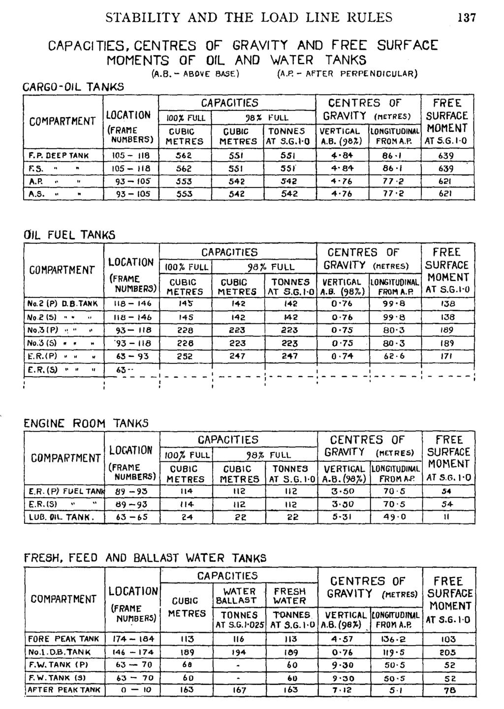
142 STABILITY AND THE LOAD LINE RULES 135 chapter and in the scales in the back of this book. Some parts have here been abbreviated, or merely described, in order to save space: but it is hoped that this will be sufficient to give the reader a clear idea of the main contents of the booklet, which are as follows:- (a) General particulars of the ship (name, official number, dimensions, tonnage, etc.). (b) Plans of the ship, shewing cargo, tank, store spaces, etc. (c) Special notes regarding the stability and loading of the ship: both in general and as applied to that particular vessel. (d) Hydrostatic particulars for the ship in salt water. (See the example given in the back of this book.) (e) Capacities and centres of gravity of cargo spaces, storerooms, crew spaces, etc. (See Plate in this chapter.) (f) Capacities, centres of gravity and free surface moments of oil and water tanks. (Also in this chapter.) (g) Notes on the use of free surface moments. (Here described in Chapter 9.) (h) Special information required if the ship is designed to carry containers: including a container stowage plan and a statement indicating the position of the centre of gravity of each container. (i) Cross curves of stability (KN curves) and an example shewing their use. (Described here in Chapter 13.) (;) A deadweight scale. (See the example given in the back of this book.) (k) Condition sheets, giving a plan and details of weights on board, information on stability on departure or arrival, and a curve of statical stability: all for at least each of the following conditions:- (i) The light ship. (ii) Ballast conditions on (a) departure and (b) arrival. (iii) The ship loaded to the summer load line with homogeneous cargo on (a) departure and (b) arrival. (iv) The ship loaded to the summer load line in at least one service loaded condition on (a) departure and (b) arrival. For the above purposes, it is assumed that:- For each "Arrival Condition", all fuel, fresh water and consumable stores have been reduced to 10% of their original amounts. In the "departure condition", fuel tanks which are "full" of oil are taken as 98% full. An abbreviated example of the ship in condition 3 (a) is given in this chapter.
143
144
145
146
147 140 MERCHANT SHIP STABILITY Maximum total moment = W x KG = 1259 X = 4541tlm Moment of light ship = 737 X = 2432 tlm Maximum permissible deadweight moment = 2109 tlm The above is repeated for a series of drafts between the light and load waterlines and, from this, a scale or graph is drawn up to shew the maximum permissible deadweight moment for each draft. The seaman is given a copy of this scale and/or graph: also a form on which is shewn a profile of the ship and the heights of the centres of gravity of the various compartments. He enters on this form, the amount and Kg of each item on board and multiplies them together to find its deadweight moment. The sum of these moments will be the actual deadweight moment of the ship. The seaman also extracts from the scale or graph, the maximum permissible deadweight moment for his ship's draft or displacement. As long as the actual deadweight moment is less than the maximum permissible moment, the ship will have a sufficient GM. An example of the above is shewn in the following two diagrams. The first of these shews the maximum permissible deadweight moments for an imaginary small ship. The second shews a completed form for the same ship, when loaded: indicating that at a displacement of 1861 tonnes, the ship has an actual deadweight moment of 3702 tonne-metres. The maximum permissible deadweight moment for the ship's displacement is then extracted from the first diagram (in this case it is 4141 t/m): this is entered at the bottom of the second form. This then shews that, in this case, the ship has sufficient GM, since the actual moment is less than the maximum permissible moment. "Simplified Stability Information".-This may be provided as an addition to the basic data and sample loading conditions required by the Rules. This information may be presented in one of three ways, provided that it is accompanied by clear guidance notes for its use:- (a) A maximum deadweight diagram or table. (b) A diagram or table shewing maximum permissible KGs. (c) A diagram or table shewing minimum permissible GMs. The method of setting out the diagrams or tables for KGs or GMs would be basically similar to those shewn here for deadweight moments.
148
149 140 MERCHANT SHIP STABILITY Maximum total moment = W x KG = 1259 x = 4541 t/m Moment of light ship = 737 x = 2432 t/m Ma.ximum permissible deadweight moment = 2109 t/m The above is repeated for a series of drafts between the light and load waterlines and, from this, a scale or graph is drawn up to shew the maximum permissible deadweight moment for each draft. The seaman is given a copy of this scale and/or graph: also a form on which is shewn a profile of the ship and the heights of the centres of gravity of the various compartments. He enters on this form, the amount and Kg of each item on board and multiplies them together to find its deadweight moment. The sum of these moments will be the actual deadweight moment of the ship. The seaman also extracts from the scale or graph, the maximum permissible deadweight moment for his ship's draft or displacement. As long as the actual deadweight moment is less than the maximum permissible moment, the ship will have a sufficient GM. An example of the above is shewn in the following two diagrams. The first of these shews the maximum permissible deadweight moments for an imaginary small ship. The second shews a completed form for the same ship, when loaded: indicating that at a displacement of 1861 tonnes, the ship has an actual deadweight moment of 3702 tonne-metres. The maximum permissible deadweight moment for the ship's displacement is then extracted from the first diagram (in this case it is 4141 t/m): this is entered at the bottom of the second form. This then shews that, in this case, the ship has sufficient GM, since the actual moment is less than the maximum permissible moment. "Simplified Stability Information".-This may be provided as an addition to the basic data and sample loading conditions required by the Rules. This information may be presented in one of three ways, provided that it is accompanied by clear guidance notes for its use:- (a) (b) (c) A maximum deadweight diagram or table. A diagram or table shewing maximum permissible KGs. A diagram or table shewing minimum permissible GMs. The method of setting out the diagrams or tables for KGs or GMs would be basically similar to those shewn here for deadweight moments.
150
151

152 CHAPTER 16 MISCELLANEOUS MATTERS Drydocking.- When a ship' is drydocked, her support has to be transferred from the water to the keel blocks and shores. She may be considered safe whilst she is waterborne, or once the shores have been set up, but thereis a danger that she may become unstable during the intervening period. which is often termed the "critical period". Whilst the dock is being pumped out, the ship at first sinks bodily as thewater-level falls, but as soon as she touches the keel blocks she stops sinking. and the water falls around her. She thus loses displacement so that weight, equal to the amount of the lost displacement, is transferred to the blocks. As. far as the ship's stability is concerned, this weight is equivalent to a force acting vertically upwards at the keel and it will decrease the metacentricheight. The latter must, sooner or later, become negative and if this were to, happen before the shores were properly set up, the ship might capsize in thedock. It is thus of the utmost importance to keep full control of the ship, during the critical period and to get the s~ores set up as soon as possible. Toassist in this, it is usual to have the ship trimmed a little by the stern when she enters the dock, so that the heel of the stern post is the first part to touch. the blocks.
153 144 MERCHANT SHIP STABILITY height, or the weights on board not being symmetrical about the centre-line. In the first case, the ship would be certain to fall over as soon as her keel touched the blocks. In the second, she might fall over at some time during the critical period on account of the excess of weight on one side. Before the ship is floated again, it is very important to check any weights which may have been shifted whilst she is in the dock; otherwise we may have a similar effect to the above whilst the dock is being filled. In this respect, do not forget to make sure that boilers have not been filled or emptied, or to check-up on any weights shifted in the engine-room. The procedure of dry docking is, briefly, as follows. As soon as the ship enters the dock she usually comes under the control of the foreman carpenter or shipwright, who manoeuvres her into the position PP. requires. The dock gates are then closed and pumping-out commences. When the ship's stern is nearly on the blocks, pumping is stopped whilst the ship is aligned so that her centre-line is exactly over them. Pumping is then resumed slowly until the stern touches the blocks, when the after shores are put-in loosely. As the ship settles down, more shores are put-in, working from aft forward, and as soon as the keel comes flat on the blocks any remaining shores are put in place and all are set-up as quickly as possible. The heads of shores should always be placed on frames and not between them, in order to eliminate the risk of denting the ship's plating. Once the shores have been set-up, pumping is continued quickly until the dock is dry. The following formula will give the ship's metacentric during the process of drydocking:- Where P = the force acting upwards through the keel. KM = height of the metacentre on entering the dock. W = ship's displacement on entering dock. height at any time
154
155
156 Reserve Buoyancy.-In the case of a ship, this is the volume of the hull betwe.en the water-line and the freeboard deck. It amounts, approximately to the difference between the actual displacement and that which the ship would have if she were submerged to her freeboard deck. We can calculate the reserve buoyancy for any floating body by finding the difference between the total watertight volume of the body and the volume of water which it displaces. Continuous Watertight Longitudinal Bulkheads.-These give great longitudinal strength to a ship and also reduce free surface effect when liquids are carried in bulk. They have one serious disadvantage, however, in that if the ship is holed on one side and the bulkhead remains intact, the compartment could become flooded on one side only. This would give the ship a list, which may be dangerous if the compartment is large.
157 148 MERCHANT SHIP STABILITY In ordinary cargo ships, having large holds. there would be considerable risk ofcthe ship capsizing in the above circumstances. There is normally no free surface effect to be reduced in the holds and the bulkheads have the additional disadvantage that they interfere with the handling of cargo. Consequently continuous longitudinal bulkheads are not fitted in ordinary cargo ships, -since the disadvantages outweigh the gain in longitudinal strength. In the case of oil-tankers, carrying bulk liquid cargoes, some form of longitudinal subdivision is necessary to minimise free surface effect. Interference with the stowage of cargo does not have to be considered and great longitudinal strength is required. In such ships. the advantages of continuous longitudinal bulkheads are obvious and one or two are always fitted. The danger of the vessel's capsizing in the event of her being bilged is overcome by restricting the length of her tanks. Also. in the event of a tank on one side becoming flooded, the corresponding tank on the other side could be filled quickly to counterbalance this. Non-Continuous Longitudinal Bulkheads.-These are often fitted in ordinary ships. as they ha ve a number of structural advantages. Since they are not continuous throughout any hold. they do not affect the ship's stability. Bulkhead Subdivision and Sheer.-The subdivision of a ship into compartments by means of transverse bulkheads is a great factor in determining her safety if she is holed. It is not generally realised by seamen that sheer also plays an important part in this if the ship is holed forward or abaft the centre of the flotation. In 1912, a committee was set up to investigate the spacing of bulkheads and the suggestions which were made in their report are now compulsory for passenger ships. It was not possible to apply them to cargo ships also and the bulkheads in the latter are usually more widely spaced than would be allowed in passenger vessels. The committee introduced the "Margin Line" and the "Curve of Floodable Lengths". The Margin Line is an imaginary line. 75 millimetres below the bulkhead deck. It is assumed that a ship which was sunk to this line would still be navigable in fine weather. The Curve of Floodable Lengths is a graph from which can be found the floodable lengths for any part of the ship. i.e. that length of the ship which. if flooded. would cause her to sink to her margin line. When this is calculated. allowance is made for an assumed average permeability in each of the various compartm~nts. The length allowed for any compartment is found by multiplying the floodable length by a factor which depends on the length of the ship and on a number of other things.
158
SECOND ENGINEER REG III/2 NAVAL ARCHITECTURE
 SECOND ENGINEER REG III/2 NAVAL ARCHITECTURE LIST OF TOPICS A B C D E F G H I J Hydrostatics Simpson's Rule Ship Stability Ship Resistance Admiralty Coefficients Fuel Consumption Ship Terminology Ship
This lesson will be confined to the special case of ships at rest in still water. Questions of motions resulting from waves are not considered at
 STATIC STABILITY When we say a boat is stable we mean it will (a) float upright when at rest in still water and (b) return to its initial upright position if given a slight, temporary deflection to either
Marine Kit 4 Marine Kit 4 Sail Smooth, Sail Safe
 Marine Kit 4 Marine Kit 4 Sail Smooth, Sail Safe Includes Basic ship Terminologies and Investigation Check list Index 1. Ship Terminology 03 2. Motions of a Floating Body...09 3. Ship Stability.10 4. Free
S0300-A6-MAN-010 CHAPTER 2 STABILITY
 CHAPTER 2 STABILITY 2-1 INTRODUCTION This chapter discusses the stability of intact ships and how basic stability calculations are made. Definitions of the state of equilibrium and the quality of stability
OPERATIONS SEAFARER CERTIFICATION GUIDANCE NOTE SA MARITIME QUALIFICATIONS CODE
 Page 1 of 8 Compiled by Chief Examiner Approved by Qualifications Committee: 27 September 2013 OPERATIONS SEAFARER CERTIFICATION GUIDANCE NOTE SA MARITIME QUALIFICATIONS CODE Page 2 of 8 KNOWLEDGE, UNDERSTANDING
Chapter 2 Hydrostatics and Control
 Chapter 2 Hydrostatics and Control Abstract A submarine must conform to Archimedes Principle, which states that a body immersed in a fluid has an upward force on it (buoyancy) equal to the weight of the
Final KG plus twenty reasons for a rise in G
 Chapter 3 Final KG plus twenty reasons for a rise in G hen a ship is completed by the builders, certain written stability information must be handed over to the shipowner with the ship. Details of the
Hydrostatics and Stability Dr. Hari V Warrior Department of Ocean Engineering and Naval Architecture Indian Institute of Technology, Kharagpur
 Hydrostatics and Stability Dr. Hari V Warrior Department of Ocean Engineering and Naval Architecture Indian Institute of Technology, Kharagpur Module No. # 01 Lecture No. # 22 Righting Stability II We
CERTIFICATES OF COMPETENCY IN THE MERCHANT NAVY MARINE ENGINEER OFFICER
 CERTIFICATES OF COMPETENCY IN THE MERCHANT NAVY MARINE ENGINEER OFFICER EXAMINATIONS ADMINISTERED BY THE SCOTTISH QUALIFICATIONS AUTHORITY ON BEHALF OF THE MARITIME AND COASTGUARD AGENCY STCW 95 CHIEF
Hydrostatics and Stability Prof. Dr. Hari V Warrior Department of Ocean Engineering and Naval Architecture Indian Institute of Technology, Kharagpur
 Hydrostatics and Stability Prof. Dr. Hari V Warrior Department of Ocean Engineering and Naval Architecture Indian Institute of Technology, Kharagpur Module No. # 01 Lecture No. # 23 Trim Calculations -
Stability Information Booklet. Priority Pontoon
 Stability Information Booklet Priority Pontoon Lightship Index General Particulars...3 General Details...4 Plan - GA...5 Plan - Frames...6 General Precautions against capsizing...7 Special Notes Regarding
Chapter 3 Hydrostatics and Floatation
 Chapter 3 Hydrostatics and Floatation Naval Architecture Notes 3.1 Archimedes Law of Floatation Archimedes (born 287 B.C) Law states that An object immersed in a liquid experience a lift equivalent to
Safety practices related to small fishing vessel stability
 18 The vessel s centre of gravity (G) has a distinct effect on the righting lever (GZ) and consequently the ability of a vessel to return to the upright position. The lower the centre of gravity (G), the
Load lines and freeboard marks
 Chapter 8 Load lines and freeboard marks The link Freeboard and stability curves are inextricably linked. With an increase in the freeboard: Righting levers (GZ) are increased. GM T increases. Range of
Ship Stability. Ch. 8 Curves of Stability and Stability Criteria. Spring Myung-Il Roh
 Lecture Note of Naval Architectural Calculation Ship Stability Ch. 8 Curves of Stability and Stability Criteria Spring 2016 Myung-Il Roh Department of Naval Architecture and Ocean Engineering Seoul National
Visit Us:
 Visit Us: www.officerofthewatch.co.uk www.officerofthewatch.co.uk JUL-Y 2005 STABILITY AND STRUCTURE Attempt ALL questions Marks for each part question are shown in brackets 1. A vessel is to transit
ANNEX 5 IMO MARINE CASULATY AND INCIDENT REPORT DAMAGE CARDS* AND INTACT STABILITY CASUALTY RECORDS
 ANNEX 5 IMO MARINE CASUATY AND INCIDENT REPORT DAMAGE CARDS* AND INTACT STABIITY CASUATY RECORDS Statistics of damaged ships and of intact stability casualties are important to the work of the Organization
CLASS 1E 8 SMOOTH WATERS OPERATIONS 8
 Table of Contents INSTRUCTION TO MASTERS SAFETY INFORMATION 3 STABILITY BOOK TO BE KEPT ON VESSEL 3 LOADING CONDITIONS 3 ASPECTS OF LOADING 3 PASSENGER PARTICULARS 3 HYDROSTATIC AND KN VALUES 4 EXCESS
SHIP FORM DEFINITION The Shape of a Ship
 SHIP FORM DEFINITION The Shape of a Ship The Traditional Way to Represent the Hull Form A ship's hull is a very complicated three dimensional shape. With few exceptions an equation cannot be written that
Definitions 13 FREE SURFACE EFFECT
 Definitions 13 FREE SURFACE EFFECT When a vessel with a full tank is heeled, the liquid within the tank acts like a solid mass. Its centre of gravity, being the centre of its volume, remains constant and
Chapter 5 Transverse Stability
 Chapter 5 Transverse Stability Naval Architecture Notes Consider a ship floating upright as shown in Figure 5.1. The centres of gravity and buoyancy are on the centre line. The resultant force acting on
RULES PUBLICATION NO. 86/P EXPLANATORY NOTES TO SOLAS CONVENTION AND DIRECTIVE 2003/25/EC STABILITY AND SUBDIVISION REQUIREMENTS
 RULES PUBLICATION NO. 86/P EXPLANATORY NOTES TO SOLAS CONVENTION AND DIRECTIVE 2003/25/EC STABILITY AND SUBDIVISION REQUIREMENTS 2011 Publications P (Additional Rule Requirements) issued by Polski Rejestr
FREE SURFACE EFFECTS. Partially-filled (slack) tanks can be dangerous; the number of slack tanks should be kept to a minimum.
 tanks can be dangerous; the number of slack tanks should be kept to a minimum.") 26 FREE SURFACE EFFECTS Care should always be taken to ensure the quick release of water trapped on deck. Locking freeing port covers is dangerous. If locking devices are fitted, the opening mechanism
26 FREE SURFACE EFFECTS Care should always be taken to ensure the quick release of water trapped on deck. Locking freeing port covers is dangerous. If locking devices are fitted, the opening mechanism
WATERTIGHT INTEGRITY. Ship is divided into watertight compartments by means of transverse and longitudinal bulkheads bulkheads.
 Damage Stability WATERTIGHT INTEGRITY Ship is divided into watertight compartments by means of transverse and longitudinal bulkheads bulkheads. When a watertight compartment (or a group of compartments)
STABILITY & TRIM (MT4241)
") MASSACHUSETTS MARITIME ACADEMY DEPARTMENT OF MARINE TRANSPORTATION STABILITY & TRIM (MT4241) I. LEARNING OBJECTIVES FALL 2015 This course is designed to meet all stability, knowledge based assessments,
MASSACHUSETTS MARITIME ACADEMY DEPARTMENT OF MARINE TRANSPORTATION STABILITY & TRIM (MT4241) I. LEARNING OBJECTIVES FALL 2015 This course is designed to meet all stability, knowledge based assessments,
The Physics of Water Ballast
 The Physics of Water Ballast Nick Newland recently wrote an informative article on water ballast for Water Craft magazine (Newland 2015). Following a discussion on the Swallow Boats Association Forum,
STCW 1974, as amended, Regulation II: Written Assessment Syllabus for Bahamas Deck Officer Certificate of Competency:
 STCW 1974, as amended, Regulation II: Written Assessment Syllabus for Bahamas Deck Officer Certificate of Competency: Contents 1. Officer in Charge of Navigation Watch (OICNW) STCW Regulation II/1 (unlimited)
RULES FOR THE CLASSIFICATION AND CONSTRUCTION OF SEA-GOING SHIPS
 RULES FOR THE CLASSIFICATION AND CONSTRUCTION OF SEA-GOING SHIPS PART IV STABILITY AND SUBDIVISION 2015 July GDAŃSK RULES FOR THE CLASSIFICATION AND CONSTRUCTION OF SEA-GOING SHIPS prepared and edited
Ship Stability: Theory and Practical Application (SCQF level 8)
") Higher National Unit Specification General information Unit code: HR0L 35 Superclass: XQ Publication date: September 2017 Source: Scottish Qualifications Authority Version: 2 Unit purpose This unit is
Higher National Unit Specification General information Unit code: HR0L 35 Superclass: XQ Publication date: September 2017 Source: Scottish Qualifications Authority Version: 2 Unit purpose This unit is
Subj: Explanation of Upper Level Capacity and Stability Characteristics for Rolling Boat, Inc. Vessels.
 23 Apr, 2009 From: Tullio Celano III P.E. To: Underwriters of Rolling Boat, Inc. Via: Phil Kazmierowicz, President, Rolling Boat, Inc. Subj: Explanation of Upper Level Capacity and Stability Characteristics
STABILITY OF MULTIHULLS Author: Jean Sans
 STABILITY OF MULTIHULLS Author: Jean Sans (Translation of a paper dated 10/05/2006 by Simon Forbes) Introduction: The capsize of Multihulls requires a more exhaustive analysis than monohulls, even those
Have you seen a truck weighing bridge? Do you know how it works?
 Have you seen a truck weighing bridge? Do you know how it works? Weigh bridge It weighs the empty weight of the truck and then the loaded weight. The difference is the weight of the cargo on that truck.
Ship knowledge questions
 Part 1 Ship knowledge questions 1. In the following sketch, label the parts indicated by ( ). 2. In the following sketch, label the parts indicated by ( ). 3. In the following sketch, label the indicated
RESOLUTION MSC.235(82) (adopted on 1 December 2006) ADOPTION OF THE GUIDELINES FOR THE DESIGN AND CONSTRUCTION OF OFFSHORE SUPPLY VESSELS, 2006
 (adopted on 1 December 2006) ADOPTION OF THE GUIDELINES FOR THE DESIGN AND CONSTRUCTION OF OFFSHORE SUPPLY VESSELS, 2006") MSC 82/24/Add.2 RESOLUTION MSC.235(82) CONSTRUCTION OF OFFSHORE SUPPLY VESSELS, 2006 THE MARITIME SAFETY COMMITTEE, RECALLING Article 28(b) of the Convention on the International Maritime Organization
MSC 82/24/Add.2 RESOLUTION MSC.235(82) CONSTRUCTION OF OFFSHORE SUPPLY VESSELS, 2006 THE MARITIME SAFETY COMMITTEE, RECALLING Article 28(b) of the Convention on the International Maritime Organization
CERTIFICATES OF COMPETENCY IN THE MERCHANT NAVY MARINE ENGINEER OFFICER
 CERTIFICATES OF COMPETENCY IN THE MERCHANT NAVY MARINE ENGINEER OFFICER EXAMINATIONS ADMINISTERED BY THE SCOTTISH QUALIFICATIONS AUTHORITY ON BEHALF OF THE MARITIME AND COASTGUARD AGENCY STCW 78 as amended
RULES FOR THE CONSTRUCTION AND CLASSIFICATION OF SHIPS IDENTIFIED BY THEIR MISSIONS CHAPTERS SCOPE
 PART II RULES FOR THE CONSTRUCTION AND CLASSIFICATION OF SHIPS IDENTIFIED BY THEIR MISSIONS TITLE 12 CONTAINER SHIPS SECTION 1 NAVAL ARCHITECTURE CHAPTERS A SCOPE B DOCUMENTS, REGULATIONS AND STANDARDS
National Maritime Center
 National Maritime Center Providing Credentials to Mariners (Sample Examination) Page 1 of 8 Choose the best answer to the following Multiple Choice Questions. 1. Which term indicates the rise in height
RESOLUTION MSC.141(76) (adopted on 5 December 2002) REVISED MODEL TEST METHOD UNDER RESOLUTION 14 OF THE 1995 SOLAS CONFERENCE
 (adopted on 5 December 2002) REVISED MODEL TEST METHOD UNDER RESOLUTION 14 OF THE 1995 SOLAS CONFERENCE") MSC 76/23/Add.1 RESOLUTION MSC.141(76) THE MARITIME SAFETY COMMITTEE, RECALLING Article 38(c) of the Convention on the International Maritime Organization concerning the functions of the Committee, RECALLING
MSC 76/23/Add.1 RESOLUTION MSC.141(76) THE MARITIME SAFETY COMMITTEE, RECALLING Article 38(c) of the Convention on the International Maritime Organization concerning the functions of the Committee, RECALLING
G.L.M. : the on-board stability calculator... DEMONSTRATION OPERATOR S MANUAL
 General Load Monitor G.L.M. : the on-board stability calculator... DEMONSTRATION OPERATOR S MANUAL Distributed by: DESIGN SYSTEMS & TECHNOLOGIES 150 Rue de Goa, 06600 Antibes, France tel +33.4.92 91 13
OPERATIONS SEAFARER CERTIFICATION GUIDANCE NOTE SA MARITIME QUALIFICATIONS CODE. Naval Architecture
 Page 1 of 27 Compiled by Approved by Chief Examiner Syllabus Committee: 26 July 2013 OPERATIONS SEAFARER CERTIFICATION GUIDANCE NOTE SA MARITIME QUALIFICATIONS CODE Page 2 of 27 KNOWLEDGE, UNDERSTANDING
RULES PUBLICATION NO. 94/P SUBDIVISION AND DAMAGE STABILITY OF NEW OIL TANKERS, CHEMICAL TANKERS AND GAS CARRIERS January
 RULES PUBLICATION NO. 94/P SUBDIVISION AND DAMAGE STABILITY OF NEW OIL TANKERS, CHEMICAL TANKERS AND GAS CARRIERS 2016 January Publications P (Additional Rule Requirements) issued by Polski Rejestr Statków
RULES FOR THE CLASSIFICATION AND CONSTRUCTION OF SMALL SEA-GOING SHIPS
 RULES FOR THE CLASSIFICATION AND CONSTRUCTION OF SMALL SEA-GOING SHIPS PART IV STABILITY, SUBDIVISION AND FREEBOARD 2015 January GDAŃSK RULES FOR THE CLASSIFICATION AND CONSTRUCTION OF SMALL SEA-GOING
Part 7 Fleet in service Chapter 2 Inclining test and light weight check
 RULES FOR CLASSIFICATION Inland navigation vessels Edition December 2015 Part 7 Fleet in service Chapter 2 Inclining test and light weight check The content of this service document is the subject of intellectual
National Maritime Center
 National Maritime Center Providing Credentials to Mariners Master TV to Master Less than 500 Gross Registered Tons Oceans or Near Coastal (Sample Examination) Page 1 of 6 Master TV to Master Less than
Ship Resistance and Propulsion Prof. Dr. P. Krishnankutty Ocean Department Indian Institute of Technology, Madras
 Ship Resistance and Propulsion Prof. Dr. P. Krishnankutty Ocean Department Indian Institute of Technology, Madras Lecture - 6 Bulbous Bow on Ship Resistance Welcome back to the class we have been discussing
Hydrostatics and Stability Dr. Hari V Warrior Department of Ocean Engineering and Naval Architecture Indian Institute of Technology, Kharagpur
 Hydrostatics and Stability Dr. Hari V Warrior Department of Ocean Engineering and Naval Architecture Indian Institute of Technology, Kharagpur Module No.# 01 Lecture No. # 01 Introduction Hello everybody.
NAVAL ARCHITECTURE 1. Class Notes
 NAVAL ARCHITECTURE 1 Class Notes d G G 1 W tonnes d G 1 G w tonnes d G 1 G w tonnes Omar bin Yaakob Chapter 1 Introduction Naval Architecture Notes Introduction To carry out various activities at sea,
A Study on Roll Damping of Bilge Keels for New Non-Ballast Ship with Rounder Cross Section
 International Ship Stability Workshop 2013 1 A Study on Roll Damping of Bilge Keels for New Non-Ballast Ship with Rounder Cross Section Tatsuya Miyake and Yoshiho Ikeda Department of Marine System Engineering,
APPENDIX IV DEVELOPMENT AND MEASUREMENT RULES OF THE INTERNATIONAL TEN SQUARE METER SAILING CANOE
 APPENDIX IV Development Canoe Rules APPENDIX IV DEVELOPMENT AND MEASUREMENT RULES OF THE INTERNATIONAL TEN SQUARE METER SAILING CANOE 1 GENERAL Class and measurement rules measurement forms may be obtained
APPENDIX IV DEVELOPMENT AND MEASUREMENT RULES OF THE INTERNATIONAL TEN SQUARE METRE SAILING CANOE (JANUARY 2008) 1 GENERAL
 1 GENERAL") APPENDIX IV DEVELOPMENT AND MEASUREMENT RULES OF THE INTERNATIONAL TEN SQUARE METRE SAILING CANOE (JANUARY 2008) 1 GENERAL Class and measurement rules measurement forms may be obtained from the I.C.F.
APPENDIX IV DEVELOPMENT AND MEASUREMENT RULES OF THE INTERNATIONAL TEN SQUARE METRE SAILING CANOE (JANUARY 2008) 1 GENERAL Class and measurement rules measurement forms may be obtained from the I.C.F.
FLUID MECHANICS. Fluid Statics BUOYANCY. Fig. Buoyancy CENTER OF BUOYANCY
 FLUID MECHANICS Fluid Statics BUOYANCY When a body is either wholly or partially immersed in a fluid, the hydrostatic lift due to the net vertical component of the hydrostatic pressure forces experienced
DUKC DYNAMIC UNDER KEEL CLEARANCE
 DUKC DYNAMIC UNDER KEEL CLEARANCE Information Booklet Prepared in association with Marine Services Department 10/10/2005 Dynamic Under Keel Clearance (DUKC) integrates real time measurement of tides and
MSC Guidelines for the Submission of Stability Test (Deadweight Survey or Inclining Experiment) Results
 Results") S. E. HEMANN, CDR, Chief, Hull Division References a. 46 CFR 170, Subpart F Determination of Lightweight Displacement and Centers of Gravity b. NVIC 17-91 Guidelines for Conducting Stability Tests c. ASTM
S. E. HEMANN, CDR, Chief, Hull Division References a. 46 CFR 170, Subpart F Determination of Lightweight Displacement and Centers of Gravity b. NVIC 17-91 Guidelines for Conducting Stability Tests c. ASTM
Fishing Vessel Stability
 Fishing Vessel Stability Or How To Stay Upright Fishing Vessel Stability What It Is? How Does It Work? What is Adequate Stability? What Happens During Typical Fishing Operations? 1 What is Stability? Stability
National Maritime Center
 National Maritime Center Providing Credentials to Mariners (Sample Examination) Page 1 of 7 Choose the best answer to the following Multiple Choice Questions. 1. The sailing drafts are: FWD 14'-08", AFT
Part 3 Pressure hull and structures Chapter 7 Stability and buoyancy
 RULES FOR CLASSIFICATION Underwater technology Edition December 2015 Part 3 Pressure hull and structures Chapter 7 The content of this service document is the subject of intellectual property rights reserved
MSC Guidelines for Review of Stability for Towing Vessels (M)
") S. E. HEMANN, CDR, Chief, Hull Division References Contact Information a. 46 CFR Subchapter M, Part 144 b. 46 CFR Subchapter S, Parts 170, 173 c. Navigation and Vessel Circular No. 17-91, CH 1, Guidelines
S. E. HEMANN, CDR, Chief, Hull Division References Contact Information a. 46 CFR Subchapter M, Part 144 b. 46 CFR Subchapter S, Parts 170, 173 c. Navigation and Vessel Circular No. 17-91, CH 1, Guidelines
An Investigation into the Capsizing Accident of a Pusher Tug Boat
 An Investigation into the Capsizing Accident of a Pusher Tug Boat Harukuni Taguchi, National Maritime Research Institute (NMRI) taguchi@nmri.go.jp Tomihiro Haraguchi, National Maritime Research Institute
OFFSHORE RACING CONGRESS World Leader in Rating Technology
 OFFSHORE RACING CONGRESS World Leader in Rating Technology ORC SY MEASUREMENT GUIDANCE 2017 1. INTRODUCTION This paper must be taken as guidance for the process of boat measurement to allow for the issuance
PART 1 GENERAL REQUIREMENTS
 PART 1 GENERAL REQUIREMENTS SECTION SUBJECT 1.1 Standards 1.2 Compliance procedures and certification 1.3 Building premises 1.4 Testing of structures 1.5 Materials 1.6 Definitions of expressions GENERAL
Chapter 3 PRESSURE AND FLUID STATICS
 Fluid Mechanics: Fundamentals and Applications, 2nd Edition Yunus A. Cengel, John M. Cimbala McGraw-Hill, 2010 Chapter 3 PRESSURE AND FLUID STATICS Lecture slides by Hasan Hacışevki Copyright The McGraw-Hill
Numerical Modelling Of Strength For Hull Form Components Of A 700 Tonne Self-Propelled Barge Under Moment And Operational Loading
 IOSR Journal of Engineering (IOSRJEN) ISSN (e): 2250-3021, ISSN (p): 2278-8719 Vol. 05, Issue 05 (May. 2015), V1 PP 45-55 www.iosrjen.org Numerical Modelling Of Strength For Hull Form Components Of A 700
GUIDANCE NOTICE. Unpowered Barges. Definition. General. Risk assessment. Application. Safety Management. Compliance
 GUIDANCE NOTICE Unpowered Barges Definition Unpowered Barge - a vessel that is not propelled by mechanical means and is navigated by a powered vessel that moves it by pushing or towing. General This notice
MSC Guidelines for the Review of OSV Stability
 MSC Guidelines for the Review of OSV Stability Procedure Number: C1-06 Revision Date: February 13, 2013 R. J. LECHNER, CDR, Tank Vessel and Offshore Division Purpose To establish a procedure for reviewing
Understanding How Excessive Loading Lead to a Capsize with Loss of Life Can Help Avoid Future Tragedies
 Understanding How Excessive Loading Lead to a Capsize with Loss of Life Can Help Avoid Future Tragedies By Dave Gerr, CEng FRINA 2012 Dave Gerr fter sailing out to watch the fireworks on July 4th, 2012,
In the liquid phase, molecules can flow freely from position to position by sliding over one another. A liquid takes the shape of its container.
 In the liquid phase, molecules can flow freely from position to position by sliding over one another. A liquid takes the shape of its container. In the liquid phase, molecules can flow freely from position
Investigation of the Intact Stability Accident of the Multipurpose Vessel MS ROSEBURG
 Proceedings of the 12th International Conference on the Stability of Investigation of the Intact Stability Accident of the Multipurpose Vessel MS ROSEBURG Adele Lübcke, Institute of Ship Design and Ship
COURSE NUMBER: ME 321 Fluid Mechanics I Fluid statics. Course teacher Dr. M. Mahbubur Razzaque Professor Department of Mechanical Engineering BUET
 COURSE NUMBER: ME 321 Fluid Mechanics I Fluid statics Course teacher Dr. M. Mahbubur Razzaque Professor Department of Mechanical Engineering BUET 1 Fluid statics Fluid statics is the study of fluids in
In the liquid phase, molecules can flow freely from position. another. A liquid takes the shape of its container. 19.
 In the liquid phase, molecules can flow freely from position to position by sliding over one another. A liquid takes the shape of its container. In the liquid phase, molecules can flow freely from position
Policy for the Implementation of International Load Lines
 IDEPARTMENT OF MARINE ADMIN STRATION MYANMAR Department of Marine Administration - Yangon Myanmar Policy for the Implementation of International Load Lines Operational Procedure : QOP - 72-01- (05) Revision:
MSC Guidelines for Review of Stability for Sailing Catamaran Small Passenger Vessels (T)
") K.B. FERRIE, CDR, Chief, Hull Division References: a. 46 CFR Subchapter T, Parts 178, 179 b. 46 CFR Subchapter S, Parts 170, 171 c. Marine Safety Manual (MSM), Vol. IV d. Navigation and Vessel Circular
K.B. FERRIE, CDR, Chief, Hull Division References: a. 46 CFR Subchapter T, Parts 178, 179 b. 46 CFR Subchapter S, Parts 170, 171 c. Marine Safety Manual (MSM), Vol. IV d. Navigation and Vessel Circular
(Refer Slide Time: 0:25)
") Port and Harbour Structures Prof. R. Sundaravadivelu Department of Ocean Engineering Indian Institute of Technology Madras Module 01 Lecture 04 Ships and Size of Ships So in this class we will continue
Port and Harbour Structures Prof. R. Sundaravadivelu Department of Ocean Engineering Indian Institute of Technology Madras Module 01 Lecture 04 Ships and Size of Ships So in this class we will continue
Tall Ships America Safety Under Sail Forum: Sailing Vessel Stability, Part 1: Basic Concepts
 Tall Ships America Safety Under Sail Forum: Sailing Vessel Stability, Part 1: Basic Concepts Moderator: Captain Rick Miller, MMA Panelists: Bruce Johnson, Co-Chair Working Vessel Operations and Safety
Stability and Computational Flow Analysis on Boat Hull
 Vol. 2, Issue. 5, Sept.-Oct. 2012 pp-2975-2980 ISSN: 2249-6645 Stability and Computational Flow Analysis on Boat Hull A. Srinivas 1, V. Chandra sekhar 2, Syed Altaf Hussain 3 *(PG student, School of Mechanical
Ship Stability September 2013 Myung-Il Roh Department of Naval Architecture and Ocean Engineering Seoul National University
 Planning Procedure of Naval Architecture and Ocean Engineering Ship Stability September 2013 Myung-Il Roh Department of Naval Architecture and Ocean Engineering Seoul National University 1 Ship Stability
OIL IN NAVIGABLE WATERS REGULATIONS [L.N. 101 of 1968.] under sections 5 and 7. [22nd April, 1968] [Comrnencernent.]
![OIL IN NAVIGABLE WATERS REGULATIONS [L.N. 101 of 1968.] under sections 5 and 7. [22nd April, 1968] [Comrnencernent.]](/thumbs/80/81393535.jpg "OIL IN NAVIGABLE WATERS REGULATIONS [L.N. 101 of 1968.] under sections 5 and 7. [22nd April, 1968] [Comrnencernent.]") OIL IN NAVIGABLE WATERS REGULATIONS [L.N. 101 of 1968.] under sections 5 and 7 [Comrnencernent.] [22nd April, 1968] 1. Short title and interpretation (1) These Regulations may be cited as the Oil in Navigable
OIL IN NAVIGABLE WATERS REGULATIONS [L.N. 101 of 1968.] under sections 5 and 7 [Comrnencernent.] [22nd April, 1968] 1. Short title and interpretation (1) These Regulations may be cited as the Oil in Navigable
Irrigation &Hydraulics Department lb / ft to kg/lit.
 CAIRO UNIVERSITY FLUID MECHANICS Faculty of Engineering nd Year CIVIL ENG. Irrigation &Hydraulics Department 010-011 1. FLUID PROPERTIES 1. Identify the dimensions and units for the following engineering
A guide to. fishing vessel stability
 A guide to fishing vessel stability 2017 This work has been republished with the permission of Maritime New Zealand. Contents Introduction 2 1. The importance of stability 2 The basics of stability: buoyancy
Higher National Unit Specification. General information for centres. Unit title: Ship Stability 2. Unit code: D78J 35
 Higher National Unit Specification General information for centres Unit code: D78J 35 Unit purpose: This Unit is about the theory and practice affecting stability, trim and structural loading for the safe
ANNEX 4 ALTERNATIVE TEXT FOR OPERATIONAL GUIDELINES FOR VERIFICATION OF DAMAGE STABILITY REQUIREMENTS FOR TANKERS
 Annex 4, page 1 ANNEX 4 ALTERNATIVE TEXT FOR OPERATIONAL GUIDELINES FOR VERIFICATION OF DAMAGE STABILITY REQUIREMENTS FOR TANKERS GUIDELINES FOR VERIFICATION OF DAMAGE STABILITY FOR TANKERS PART 2 OPERATIONAL
ANNEX 2 RESOLUTION MEPC.124(53) Adopted on 22 July 2005 GUIDELINES FOR BALLAST WATER EXCHANGE (G6) THE MARINE ENVIRONMENT PROTECTION COMMITTEE,
 Adopted on 22 July 2005 GUIDELINES FOR BALLAST WATER EXCHANGE (G6) THE MARINE ENVIRONMENT PROTECTION COMMITTEE,") Page 1 RESOLUTION MEPC.124(53) Adopted on 22 July 2005 GUIDELINES FOR BALLAST WATER EXCHANGE (G6) THE MARINE ENVIRONMENT PROTECTION COMMITTEE, RECALLING Article 38(a) of the Convention on the International
Page 1 RESOLUTION MEPC.124(53) Adopted on 22 July 2005 GUIDELINES FOR BALLAST WATER EXCHANGE (G6) THE MARINE ENVIRONMENT PROTECTION COMMITTEE, RECALLING Article 38(a) of the Convention on the International
Development of TEU Type Mega Container Carrier
 Development of 8 700 TEU Type Mega Container Carrier SAKAGUCHI Katsunori : P. E. Jp, Manager, Ship & Offshore Basic Design Department, IHI Marine United Inc. TOYODA Masanobu : P. E, Jp, Ship & Offshore
The Physics of Lateral Stability 1
 The Physics of Lateral Stability 1 This analysis focuses on the basic physics of lateral stability. We ask Will a boat heeled over return to the vertical? If so, how long will it take? And what is the
STRUCTURAL MEMBERS OF A SHIP. compartment stem frame beam bracket girder stern post hull angle bar stiffener
 Unit 2 SHIPS AND SHIPS TERMS STRUCTURAL MEMBERS OF A SHIP Basic terms shell plating strake keel deck tank top floor stringer buoyancy strength stability bulkhead compartment stem frame beam bracket girder
Abstract. 1 Introduction
 A computational method for calculatingthe instantaneous restoring coefficients for a ship moving in waves N. El-Simillawy College of Engineering and Technology, Arab Academyfor Science and Technology,
RULES PUBLICATION NO. 20/P SHIP SIDE STRENGTHENING OF FISHING VESSELS MOORING AT SEA ALONGSIDE OTHER VESSELS
 RULES PUBLICATION NO. 20/P SHIP SIDE STRENGTHENING OF FISHING VESSELS MOORING AT SEA ALONGSIDE OTHER VESSELS 1995 Publications P (Additional Rule Requirements), issued by Polski Rejestr Statków, complete
A Guide to the Influence of Ground Reaction on Ship Stability
 Journal of Shipping and Ocean Engineering 6 (2017) 262-273 doi 10.17265/2159-5879/2017.06.004 D DAVID PUBLISHING A Guide to the Influence of Ground Reaction on Ship Stability Ahmed Helmy Abouelfadl and
RULES PUBLICATION NO. 6/P STABILITY GDAŃSK
 RULES PUBLICATION NO. 6/P STABILITY 006 Publications P (Additional Rule Requirements) issued by Polski Rejestr Statków complete or extended the Rules and are mandatory where applicable. GDAŃSK Publication
Rules for Classification and Construction Additional Rules and Guidelines
 VI Rules for Classification and Construction Additional Rules and Guidelines 11 Other Operations and Systems 6 Guidelines for the Preparation of Damage Stability Calculations and Damage Control Documentation
MSC Guidelines for the Review of Oil Spill Response Vessels (OSRV), Lightship and Stability
, Lightship and Stability") R. J. LECHNER, CDR, Chief, Tank Vessel and Offshore Division Purpose This Plan Review Guidance (PRG) explains the requirements for seeking plan approval for stability plans and calculations from the Marine
R. J. LECHNER, CDR, Chief, Tank Vessel and Offshore Division Purpose This Plan Review Guidance (PRG) explains the requirements for seeking plan approval for stability plans and calculations from the Marine
EXPERIMENT (2) BUOYANCY & FLOTATION (METACENTRIC HEIGHT)
 BUOYANCY & FLOTATION (METACENTRIC HEIGHT)") EXPERIMENT (2) BUOYANCY & FLOTATION (METACENTRIC HEIGHT) 1 By: Eng. Motasem M. Abushaban. Eng. Fedaa M. Fayyad. ARCHIMEDES PRINCIPLE Archimedes Principle states that the buoyant force has a magnitude equal
EXPERIMENT (2) BUOYANCY & FLOTATION (METACENTRIC HEIGHT) 1 By: Eng. Motasem M. Abushaban. Eng. Fedaa M. Fayyad. ARCHIMEDES PRINCIPLE Archimedes Principle states that the buoyant force has a magnitude equal
SAMPLE MAT Proceedings of the 10th International Conference on Stability of Ships
 and Ocean Vehicles 1 Application of Dynamic V-Lines to Naval Vessels Matthew Heywood, BMT Defence Services Ltd, mheywood@bm tdsl.co.uk David Smith, UK Ministry of Defence, DESSESea-ShipStab1@mod.uk ABSTRACT
ISO NON-SAILING BOATS OF LENGTH GREATER THAN OR EQUAL TO 6 m CALCULATION WORKSHEET No. 1 Design:
 ISO 12217-1 NON-SAILING BOATS OF LENGTH GREATER THAN OR EQUAL TO 6 m CALCULATION WORKSHEET No. 1 Design: Design Category intended: Monohull / multihull: Item Symbol Unit Value Ref. Length of hull as in
A STUDY ON FACTORS RELATED TO THE CAPSIZING ACCIDENT OF A FISHING VESSEL RYUHO MARU No.5
 8 th International Conference on 49 A STUDY ON FACTORS RELATED TO THE CAPSIZING ACCIDENT OF A FISHING VESSEL RYUHO MARU No.5 Harukuni Taguchi, Shigesuke Ishida, Iwao Watanabe, Hiroshi Sawada, Masaru Tsujimoto,
RULES PUBLICATION NO. 76/P STABILITY, SUBDIVISION AND FREEBOARD OF PASSENGER SHIPS ENGAGED ON DOMESTIC VOYAGES
 RULES PUBLICATION NO. 76/P STABILITY, SUBDIVISION AND FREEBOARD OF PASSENGER SHIPS ENGAGED ON DOMESTIC VOYAGES 2006 (Consolidated text incorporating Amendments No. 1/2010, Amendments No. 2/2011 status
1. For the purposes of this standard, the maximum weight capacity of a boat is:
 1. For the purposes of this standard, the maximum weight capacity of a boat is: a. The maximum load the boat may carry plus 32 divided by 141 b. The load displayed on the capacity label c. The load displayed
BACHELOR'S DEGREE IN NAUTICAL SCIENCE AND MARITIME TRANSPORT (Syllabus 2010). (Teaching unit Compulsory) 6 Teaching languages: Catalan, Spanish
. (Teaching unit Compulsory) 6 Teaching languages: Catalan, Spanish") Coordinating unit: Teaching unit: Academic year: Degree: ECTS credits: 2018 280 - FNB - Barcelona School of Nautical Studies 742 - CEN - Department of Nautical Sciences and Engineering BACHELOR'S DEGREE
Coordinating unit: Teaching unit: Academic year: Degree: ECTS credits: 2018 280 - FNB - Barcelona School of Nautical Studies 742 - CEN - Department of Nautical Sciences and Engineering BACHELOR'S DEGREE
CHAPTER II-1 B. Construction subdivision and stability, machinery and electrical installations
 Only the Danish version is authentic Notice D II-1 B 1 October 2002 Technical regulation on the construction and equipment, etc. of passenger ships on domestic voyages CHAPTER II-1 B Construction subdivision
Exam Question 9: Hydrostatics. March 6, Applied Mathematics: Lecture 8. Brendan Williamson. Introduction. Density, Weight and Volume
 Exam Question 9: Hydrostatics March 6, 2017 This lecture is on hydrostatics, which is question 9 of the exam paper. Most of the situations we will study will relate to objects partly or fully submerged
Note to Shipbuilders, shipowners, ship Managers and Masters. Summary
 MARINE GUIDANCE NOTE MGN 301 (M+F) Manoeuvring Information on Board Ships Note to Shipbuilders, shipowners, ship Managers and Masters This note supersedes Marine Guidance Note MGN 201 (M+F) Summary The