Helicopters / Vortex theory. Filipe Szolnoky Cunha
|
|
|
- Sheena Blake
- 5 years ago
- Views:
Transcription


1 Vortex Theory Slide 1


2 Vortex Theory Slide 2

3 Vortex Theory µ=0.2 Slide 3

4 Vortex Theory µ=0.4 Slide 4

5 Vortex Theory Slide 5
6 Tip Vortex Trajectories Top view Slide 6
7 Definition Wake Age Slide 7
8 Assumptions: Tip Vortex Trajectories Wake undistorted in in the x-y plane Trajectories closely follow epicycloidal forms Then the trajectories can be described by the parametric equations: Slide 8
9 Blade Vortex Interactions Then locus of all potential BVI can be determined if both following equations are satisfied for r (on the blade) and ψ b : Slide 9
10 Blade Vortex Interactions With the solution : Only the real part is of interest: With the corresponding value of r: Slide 10
11 Blade Vortex Interactions Finally we can obtain the xand yvalues : With By solving for ψ b and r for numerical values of ψ w >0 we can determine all the locations of potential BVI intersection points Slide 11
12 Blade Vortex Interactions Slide 12

13 Blade Vortex Interactions Slide 13
14 Vortex Theory Extension of Prandtl s Lifting Line Theory Uses a combinationof Kutta-Joukowski Theorem Biot-Savart Law Empirical Prescribed Wake or Free Wake Representation of Tip Vortices and Inner Wake Robin Gray proposed the prescribed wake model in Landgrebe generalized Gray s model with extensive experimental data. was the extensively used in the 1970s and 1980s for rotor performance calculations, and is slowly giving way to CFD methods. Slide 14
15 Vortex Theory addresses some of the drawbacks of combined blade element-momentum theory methods,athighthrustsettings(highc T /σ). At these settings, the inflow velocity is affected by the contraction of the wake. Near the tip, there can be an upward directed inflow (rather than downward directed) due to this contraction, which increases the tip loading, and alters the tip power consumption. Slide 15
16 Kutta-Joukowsky Theorem The link between lift per unit length of span an the local circulation is: Since: Slide 16
17 Kutta-Joukowsky Theorem We had already seen that: So we can write: We a uniform circulation along the blade span, Helmholtz s theorem requires a single vortex of thesamestrengthtotrailfromthebladetips Slide 17
18 Representation of Bound and Trailing Vortices Since vorticity can not abruptly increase in space, trailing vortices develop.. Slide 18
19 Biot-Savart Law Fundamental to all vortex models is the requirement to compute the induced velocity at a point contributed by a vortex filament: Slide 19

20 Biot-Savart Law A different expression can be found: Control Point A Γ n B Vortex Segment Slide 20

21 Vortex Velocity model To avoid having a infinite velocity when r 0, the vortex is modelled having a outer potential flow region and inner solid body rotation region Slide 21
22 Vortex Velocity model The core radius, r c, is defined as the radial locationwherev θ ismaximum ThereforeV θ ismaximumat This boundary demarcates the inner (pure rotation) flow field from the outer(potential) flow Slide 22
23 Vortex Velocity model The simplest model is the Rankine vortex model where; The coreis modelled as asolidbodyrotation Velocity outside decreases hyperbolically with the distance Slide 23
24 Vortex Velocity model An alternative is the Oseen-Lamb vortex model, obtained through a simplified form of the Navier- Stokes equations: Whereα= Slide 24
25 Vortex Velocity model Newman has also derived exponential solutions for the three components of velocity in the vortex core based on a simplified Navier-Stokes formulation. The result for the swirl velocity is the same as that for the Ossen-Lamb model but Newman shows that the axial velocityin thevortexcoreis A is a constant that can be related to the drag on the generating lifting surface Slide 25
26 Vortex Velocity model A more general series of desingularized velocity profiles for columnar vortices with continuous distributions of flow quantities is given by Vastitas: Slide 26
27 Vortex Velocity model Slide 27
28 Vortex Velocity model Slide 28
29 Vortex Velocity model Slide 29
30 Vortex Core Growth The vortex core dimension is an important parameter that can be used to help define the structure and evolution of the tip vortices. The average viscous core radius can be considered as half the distance between the two velocity peaks. Slide 30

31 Vortex Core Growth Slide 31
32 Vortex Core Growth Slide 32
33 Vortex Core Growth A simple quantitative model of the growth in the vortex core radius with time can be based on Lamb s results for laminar flows Starting from the Lamb-Oseen swirls velocity profile: And with the change of variable: Slide 33
34 Vortex Core Growth The core radius r c corresponds to the value of r when V θ reaches a maximum: The solution is x=1.1209so the core radius grows with Slide 34
35 Vortex Core Growth Where α= see Lamb s vortex model. Is practice, because of turbulence generation the actual diffusion of vorticity contained in the vortexis knowntobemuchquickerthatthis. This effect, albeit very complicated on a fundamental level, can be incorporated into a model core growth equation using an average turbulent viscosity coefficient: Slide 35
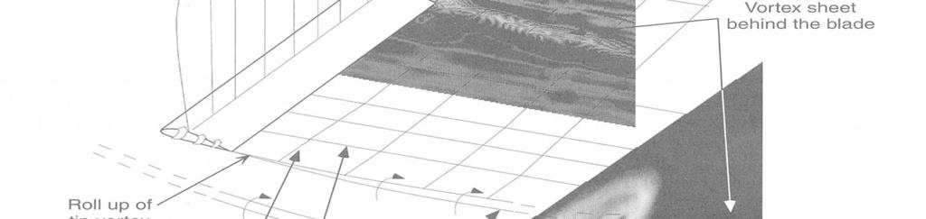
36 Howto use thistheory Wethis theorywecan: Simulate vortex sheets/ tip vortex Calculatede vortexgrowth withwake age Calculate the vortex induced velocity anywhere Letusapplythis theorytoahelicopterrotor Slide 36
37 Blade Representation Slide 37
38 Solve for Vortex Strength At the blade control points: Set-up matrix equation to solve for unknown Γ s Slide 38
39 Modelling the Vortex wake Slide 39
40 Landgrebe s Model Inner wake descendsfaster near thetipthan at theroot. Tip Vortex has a Contraction that can be fitted with an exponential curve fit. Slide 40
41 Radial Contraction Radial position of the tip vortex With the empirical values Slide 41
42 Landgrebe s Curve Fit for the Tip Vortex Contraction R w v 2v Ψ Slide 42
43 Landgrebe s Curve Fit for Tip Vortex Descent Rate Slide 43
44 Outer end Landgrebe s Curve Fit for the Vortex Sheet Inner end Slide 44
45 With Landgrebe s Curve Fit for the Vortex Sheet Slide 45
46 Wakecomparison Slide 46
47 Wakecomparison Slide 47
48 Vortex Wake Models for Forward Vortexring: Flight Stacked of vortex rings(vortex tube) Each ring is the vortex trailed by a blade during a rotation The position of the ring is defined by simple momentum theory An analytic solution for the induced velocity can be obtained Slide 48
49 Vortex Wake Models for Forward Flight Rigid or undistorted wake Trailed vortices are represented by skewed helical filaments The position of the vortex filaments is defined geometrically based on flight conditions and momentum theory conditions There are no self or mutual-interactions between vortex filaments Slide 49
50 Vortex Wake Models for Forward Flight If the tip vortex is the only one considered then its position is given by the parametric equations: Slide 50
51 Vortex Wake Models for Forward Flight Modifications for the rigid wake Other type of wake models were based on experimental results like Egolf & Landgrebe: Slide 51
52 Vortex Wake Models for Forward E is theamplitude Flight G is thegeometric function Slide 52
53 Vortex Wake Models for Forward Flight Modifications to Rigid Vortex Wake models The advantage is that with a small increase in computational effort, much better estimates of the rotor wake geometry can be obtained compared with the rigid wake Slide 53
54 Tip Vortex Representation in Computational Analyses The tip vortex is a continuous helical structure. This continuous structure is broken into piecewise straight line segments, each representing 15 degrees to 30 degrees of vortex age. The tip vortex strength is assumed to be the maximum bound circulation. Some calculations assume it to be 80% of the peak circulation. The vortex is assumed to have a small core of an empirically prescribed radius, to keep induced velocities finite. Slide 54
55 Overview of Vortex Theory Based Computations (Code supplied) Compute inflow using BEM first, using Biot-Savart law during subsequent iterations. Compute radial distribution of Loads. Convert these loads into circulation strengths. Compute the peak circulation strength. This is the strength of the tip vortex. Assume a prescribed vortex trajectory. Discard the induced velocities from BEM, use induced velocities from Biot-Savart law. Repeat until everything converges. During each iteration, adjust the blade pitch angle (trim it) if C T computed is too small or too large, compared to the supplied value. Slide 55
56 Free Wake Models These models remove the need for empirical prescription of the tip vortex structure. We march in time, starting with an initial guess for the wake. The end points of the segments are allowed to freely move in space, convected the self-induced velocity at these end points. Their positions are updated at the end of each time step. Slide 56
57 Free Wake Models Slide 57
58 Vortex Calculation (top View) Slide 58
59 Vortex Calculation (Side View) Slide 59
, Followed by Transition into Low-Speed Forward Flight:")
60 Prof. Leishman Calculations Helicopter Rotor in Low Speed Axial Descent (Incipient VRS), Followed by Transition into Low-Speed Forward Flight: Slide 60


61 Prof. Leishman Calculations Tandem Helicopter Rotor Operating in Low Speed Vertical Descent Slide 61
Incompressible Flow over Airfoils
 Road map for Chap. 4 Incompressible Flow over Airfoils Aerodynamics 2015 fall - 1 - < 4.1 Introduction > Incompressible Flow over Airfoils Incompressible flow over airfoils Prandtl (20C 초 ) Airfoil (2D)
COMPUTER-AIDED DESIGN AND PERFORMANCE ANALYSIS OF HAWT BLADES
 5 th International Advanced Technologies Symposium (IATS 09), May 13-15, 2009, Karabuk, Turkey COMPUTER-AIDED DESIGN AND PERFORMANCE ANALYSIS OF HAWT BLADES Emrah KULUNK a, * and Nadir YILMAZ b a, * New
Aerodynamic Analyses of Horizontal Axis Wind Turbine By Different Blade Airfoil Using Computer Program
 ISSN : 2250-3021 Aerodynamic Analyses of Horizontal Axis Wind Turbine By Different Blade Airfoil Using Computer Program ARVIND SINGH RATHORE 1, SIRAJ AHMED 2 1 (Department of Mechanical Engineering Maulana
UNSTEADY AERODYNAMICS OF OFFSHORE FLOATING WIND TURBINES IN PLATFORM PITCHING MOTION USING VORTEX LATTICE METHOD
 UNSTEADY AERODYNAMICS OF OFFSHORE FLOATING WIND TURBINES IN PLATFORM PITCHING MOTION USING VORTEX LATTICE METHOD Min U Jeon a *, Seung Min Lee a, Hong Seok Jeong a, Soo Gab Lee a a Department of Mechanical
9 Mixing. I Fundamental relations and definitions. Milan Jahoda revision Radim Petříček, Lukáš Valenz
 9 ixing ilan Jahoda revision 14-7-017 Radim Petříček, Lukáš Valenz I Fundamental relations and definitions ixing is a hydrodynamic process, in which different methods are used to bring about motion of
AE Dept., KFUPM. Dr. Abdullah M. Al-Garni. Fuel Economy. Emissions Maximum Speed Acceleration Directional Stability Stability.
 Aerodynamics: Introduction Aerodynamics deals with the motion of objects in air. These objects can be airplanes, missiles or road vehicles. The Table below summarizes the aspects of vehicle performance
The effect of back spin on a table tennis ball moving in a viscous fluid.
 How can planes fly? The phenomenon of lift can be produced in an ideal (non-viscous) fluid by the addition of a free vortex (circulation) around a cylinder in a rectilinear flow stream. This is known as
COMPUTATIONAL FLOW MODEL OF WESTFALL'S LEADING TAB FLOW CONDITIONER AGM-09-R-08 Rev. B. By Kimbal A. Hall, PE
 COMPUTATIONAL FLOW MODEL OF WESTFALL'S LEADING TAB FLOW CONDITIONER AGM-09-R-08 Rev. B By Kimbal A. Hall, PE Submitted to: WESTFALL MANUFACTURING COMPANY September 2009 ALDEN RESEARCH LABORATORY, INC.
WESEP 594 Research Seminar
 WESEP 594 Research Seminar Aaron J Rosenberg Department of Aerospace Engineering Iowa State University Major: WESEP Co-major: Aerospace Engineering Motivation Increase Wind Energy Capture Betz limit: 59.3%
6. EXPERIMENTAL METHOD. A primary result of the current research effort is the design of an experimental
 6. EXPERIMENTAL METHOD 6.1 Introduction A primary result of the current research effort is the design of an experimental setup that can simulate the interaction of a windmill with a vortex wake and record
Incompressible Potential Flow. Panel Methods (3)
") Incompressible Potential Flow Panel Methods (3) Outline Some Potential Theory Derivation of the Integral Equation for the Potential Classic Panel Method Program PANEL Subsonic Airfoil Aerodynamics Issues
Incompressible Potential Flow Panel Methods (3) Outline Some Potential Theory Derivation of the Integral Equation for the Potential Classic Panel Method Program PANEL Subsonic Airfoil Aerodynamics Issues
ANALYSIS OF THE CAVITATING FLOW AROUND THE HORN-TYPE RUDDER IN THE RACE OF A PROPELLER
 CAV2001:sessionB9.005 1 ANALYSIS OF THE CAVITATING FLOW AROUND THE HORN-TYPE RUDDER IN THE RACE OF A PROPELLER Jae-Moon Han, Do-Sung Kong, In-Haeng Song Shipbuilding & Plant Research Institute Samsung
Journal of Fluid Science and Technology
 Bulletin of the JSME Vol.9, No.3, 2014 Journal of Fluid Science and Technology Investigation of wind turbine flow and wake Fawaz MASSOUH* and Ivan DOBREV* * DynFluid Lab., Arts et Metiers ParisTech 151
CFD development for wind energy aerodynamics
 CFD development for wind energy aerodynamics Hamid Rahimi, Bastian Dose, Bernhard Stoevesandt Fraunhofer IWES, Germany IEA Task 40 Kick-off Meeting 12.11.2017 Tokyo Agenda BEM vs. CFD for wind turbine
A STUDY ON AIRFOIL CHRACTERISTICS OF A ROTOR BLADE FOR WIND MILL
 A STUDY ON AIRFOIL CHRACTERISTICS OF A ROTOR BLADE FOR WIND MILL Dhatchanamurthy.P 1, Karthikeyan.L.M 2, Karthikeyan.R 3 1 Department of Aeronautical Engineering, Kathir College of Engineering (India)
Computational studies on small wind turbine performance characteristics
 Journal of Physics: Conference Series PAPER OPEN ACCESS Computational studies on small wind turbine performance characteristics To cite this article: N Karthikeyan and T Suthakar 2016 J. Phys.: Conf. Ser.
Quantification of the Effects of Turbulence in Wind on the Flutter Stability of Suspension Bridges
 Quantification of the Effects of Turbulence in Wind on the Flutter Stability of Suspension Bridges T. Abbas 1 and G. Morgenthal 2 1 PhD candidate, Graduate College 1462, Department of Civil Engineering,
Incompressible Flow over Airfoils
 < 4.7 Classical Thin Airfoil Theory > The Symmetric Airfoil * Assumptions Incompressible Flow over Airfoils i) The camber line is one of the streamlines ii) Small maximum camber and thickness relative
Lift for a Finite Wing. all real wings are finite in span (airfoils are considered as infinite in the span)
") Lift for a Finite Wing all real wings are finite in span (airfoils are considered as infinite in the span) The lift coefficient differs from that of an airfoil because there are strong vortices produced
Lift for a Finite Wing all real wings are finite in span (airfoils are considered as infinite in the span) The lift coefficient differs from that of an airfoil because there are strong vortices produced
GEOMETRY TIP CAP EFFECTS ON FORMATION AND NEAR WAKE EVOLUTION OF THE ROTOR TIP VORTICES
 36th AIAA Fluid Dynamics Conference and Exhibit 5-8 June 2006, San Francisco, California AIAA 2006-3376 GEOMETRY TIP CAP EFFECTS ON FORMATION AND NEAR WAKE EVOLUTION OF THE ROTOR TIP VORTICES Roxana Vasilescu
Computational Analysis of the S Airfoil Aerodynamic Performance
 Computational Analysis of the 245-3S Airfoil Aerodynamic Performance Luis Velazquez-Araque and Jiří Nožička 2 Department of Mechanical Engineering National University of Táchira, San Cristóbal 5, Venezuela
Investigation on 3-D Wing of commercial Aeroplane with Aerofoil NACA 2415 Using CFD Fluent
 Investigation on 3-D of commercial Aeroplane with Aerofoil NACA 2415 Using CFD Fluent Rohit Jain 1, Mr. Sandeep Jain 2, Mr. Lokesh Bajpai 3 1PG Student, 2 Associate Professor, 3 Professor & Head 1 2 3
Wake modelling for offshore wind turbine parks. Jens N. Sørensen Department of Wind Energy Technical University of Denmark
 Wake modelling for offshore wind turbine parks Jens N. Sørensen Department of Wind Energy Technical University of Denmark Wake and Wind Farm Aerodynamics Basic questions and issues: How important is the
A numerical Euler-Lagrange method for bubble tower CO2 dissolution modeling
 A numerical Euler-Lagrange method for bubble tower CO2 dissolution modeling Author: Daniel Legendre & Prof. Ron Zevenhoven Åbo Akademi University Thermal and Flow Engineering Laboratory Turku, Finland
Unsteady Aerodynamics of Tandem Airfoils Pitching in Phase
 Unsteady Aerodynamics of Tandem Airfoils Pitching in Phase Ravindra A Shirsath and Rinku Mukherjee Abstract This paper presents the results of a numerical simulation of unsteady, incompressible and viscous
VORTICITY CONCENTRATION AT THE EDGE OF THE INBOARD VORTEX SHEET
 Submitted to the Journal of the American Helicopter Society VORTICITY CONCENTRATION AT THE EDGE OF THE INBOARD VORTEX SHEET J.M. Kim 1, N.M. Komerath 2, S.G. Liou 3 School of Aerospace Engineering Georgia
Inlet Swirl on Turbocharger Compressor Performance
 Inlet Swirl on Turbocharger Compressor Performance Lei Huang, Ying Liu, Hua Chen* National laboratory of Engine Turbocharging Technology, Tianjin, China *corresponding author: Tel.:+86-22-5870-7069; fax:
Bioreactor System ERT 314. Sidang /2011
 Bioreactor System ERT 314 Sidang 1 2010/2011 Chapter 2:Types of Bioreactors Week 4 Flow Patterns in Agitated Tanks The flow pattern in an agitated tank depends on the impeller design, the properties of
Numerical and Experimental Investigation of the Possibility of Forming the Wake Flow of Large Ships by Using the Vortex Generators
 Second International Symposium on Marine Propulsors smp 11, Hamburg, Germany, June 2011 Numerical and Experimental Investigation of the Possibility of Forming the Wake Flow of Large Ships by Using the
DEVELOPMENT OF A THREE-DIMENSIONAL INVERSE SAIL DESIGN METHOD
 rd High Performance Yacht Design Conference Auckland, 2- December, 2008 DEVELOPMENT OF A THREE-DIMENSIONAL INVERSE SAIL DESIGN METHOD Julien Pilate, julien_pilate@hotmail.com Frederik C. Gerhardt 2, fger00@aucklanduni.ac.nz
INFLUENCE OF AERODYNAMIC MODEL FIDELITY ON ROTOR LOADS DURING FLOATING OFFSHORE WIND TURBINE MOTIONS
 INFLUENCE OF AERODYNAMIC MODEL FIDELITY ON ROTOR LOADS DURING FLOATING OFFSHORE WIND TURBINE MOTIONS DENIS MATHA 1,2*, LEVIN KLEIN 3, DIMITRIOS BEKIROPOULOS 3, PO WEN CHENG 2 1 RAMBOLL WIND, GERMANY *
DUE TO EXTERNAL FORCES
 17B.6 DNS ON GROWTH OF A VERTICAL VORTEX IN CONVECTION DUE TO EXTERNAL FORCES Ryota Iijima* and Tetsuro Tamura Tokyo Institute of Technology, Yokohama, Japan 1. INTRODUCTION Various types of vertical vortices,
POWERED FLIGHT HOVERING FLIGHT
 Once a helicopter leaves the ground, it is acted upon by the four aerodynamic forces. In this chapter, we will examine these forces as they relate to flight maneuvers. POWERED FLIGHT In powered flight
CFD Analysis of Giromill Type Vertical Axis Wind Turbine
 242 CFD Analysis Giromill Type Vertical Axis Wind Turbine K. Sainath 1, T. Ravi 2, Suresh Akella 3, P. Madhu Sudhan 4 1 Associate Pressor, Department Mechanical Engineering, Sreyas Inst. Engg. & Tech.,
CFD ANALYSIS AND COMPARISON USING ANSYS AND STAR-CCM+ OF MODEL AEROFOIL SELIG 1223
 International Journal of Mechanical Engineering and Technology (IJMET) Volume 8, Issue 11, November 2017, pp. 312 318, Article ID: IJMET_08_11_034 Available online at http://www.iaeme.com/ijmet/issues.asp?jtype=ijmet&vtype=8&itype=11
SOARING AND GLIDING FLIGHT OF THE BLACK VULTURE
 [ 280 ] SOARING AND GLIDING FLIGHT OF THE BLACK VULTURE BY B. G. NEWMAN* Department of Engineering, University of Cambridge {Received 10 September 1957) INTRODUCTION In 1950 Raspet published an interesting
Kinematics of Vorticity
 Kinematics of Vorticity Vorticity Ω Ω= V 2 circumferentially averaged angular velocity of the fluid particles Sum of rotation rates of perpendicular fluid lines Non-zero vorticity doesn t imply spin.ω=0.
ASME International Mechanical Engineering Congress & Exhibition IMECE 2013 November 15-21, 2013, San Diego, California, USA
 ASME International Mechanical Engineering Congress & Exhibition IMECE 2013 November 15-21, 2013, San Diego, California, USA IMECE2013-62734 AERODYNAMIC CHARACTERISTICS OF HORIZONTAL AXIS WIND TURBINE WITH
Study on wind turbine arrangement for offshore wind farms
 Downloaded from orbit.dtu.dk on: Jul 01, 2018 Study on wind turbine arrangement for offshore wind farms Shen, Wen Zhong; Mikkelsen, Robert Flemming Published in: ICOWEOE-2011 Publication date: 2011 Document
Design and Blade Optimization of Contra Rotation Double Rotor Wind Turbine
 International Journal of Mechanical & Mechatronics Engineering IJMME-IJENS Vol: 11 No: 01 17 Design and Blade Optimization of Contra Rotation Double Rotor Wind Turbine Priyono Sutikno 1, Deny Bayu Saepudin
Aerofoils, Lift, Drag and Circulation
 Aerofoils, Lift, Drag and Circulation 4.0 Introduction In Section 3.3 we saw that the assumption that blade elements behave as aerofoils allows the analysis of wind turbines in terms of the lift and drag
INTRODUCTION 1.0 GENERAL
 1 Chapter INTRODUCTION 1.0 GENERAL Blower is an important class of fluid machine, which has characteristics of transfer of energy between continuous stream of fluid & an element rotating about a fixed
AIRFLOW AND TEMPERATURE FIELD CALCULATIONS FOR WINTER SPORTS FACILITIES
 AIRFLOW AND TEMPERATURE FIELD CALCULATIONS FOR WINTER SPORTS FACILITIES Andrea Frisque* Stantec Consulting, Vancouver BC V6B6A3, Canada Rowan, Williams, Davies & Irwin (RWDI), Vancouver, BC, V5Z 1K5, Canada**
Optimization of Blades of Horizontal Wind Turbines by Choosing an Appropriate Airfoil and Computer Simulation
 International Journal of Current Engineering and Technology E-ISSN 2277 4106, P-ISSN 2347 5161 2017 INPRESSCO, All Rights Reserved Available at http://inpressco.com/category/ijcet Research Article Optimization
ANALYSIS OF HEAT TRANSFER THROUGH EXTERNAL FINS USING CFD TOOL
 ANALYSIS OF HEAT TRANSFER THROUGH EXTERNAL FINS USING CFD TOOL B. Usha Rani 1 and M.E Thermal 2 1,2 Asst.Professor, Dadi Institute of Engineering and Technology, India Abstract-The rate of heat transfer
Technical Report. '. TOTAL NO OF PAGES 7b. NO orocrs. 9m. onieinaton't HEPOKT NUMBCMISI ASRL 157-1
 UNCLASSIFIED S«Tunly ri«i»ific«lion DOCUMENT CONTROL DATA R&D Srrufriy rlatt$licmlten ol Uli», body of mbtlimtl mnd indrainf mnnolmtlon muil 6««i>t«>»< wh»n th» avf II tmpotl I» tlaflll»aj \ 01. o jitimo
Development of Free Vortex Wake Model for Wind Turbine Aerodynamics under Yaw Condition
 Development of Free Vortex Wake Model for Wind Turbine Aerodynamics under Yaw Condition Hamidreza Abedi Chalmers University of Technology, 9, Gothenburg, Sweden Lars Davidson, Chalmers University of Technology,
THE PENNSYLVANIA STATE UNIVERSITY SCHREYER HONORS COLLEGE DEPARTMENT OF AEROSPACE ENGINEERING BLADE ELEMENT MOMENTUM THEORY
 THE PENNSYLVANIA STATE UNIVERSITY SCHREYER HONORS COLLEGE DEPARTMENT OF AEROSPACE ENGINEERING BLADE ELEMENT MOMENTUM THEORY APPLIED TO HORIZONTAL AXIS WIND TURBINES THOMAS R. PURCELL Spring 211 A thesis
Aerodynamic Analysis of Blended Winglet for Low Speed Aircraft
 , July 1-3, 2015, London, U.K. Aerodynamic Analysis of Blended Winglet for Low Speed Aircraft Pooja Pragati, Sudarsan Baskar Abstract This paper provides a practical design of a new concept of massive
PRESSURE DISTRIBUTION OF SMALL WIND TURBINE BLADE WITH WINGLETS ON ROTATING CONDITION USING WIND TUNNEL
 International Journal of Mechanical and Production Engineering Research and Development (IJMPERD ) ISSN 2249-6890 Vol.2, Issue 2 June 2012 1-10 TJPRC Pvt. Ltd., PRESSURE DISTRIBUTION OF SMALL WIND TURBINE
Aerodynamic Design and Blade Angle Analysis of a Small Horizontal Axis Wind Turbine
 American Journal of Modern Energy 17; 3(): 3-37 http://www.sciencepublishinggroup.com/j/ajme doi: 1.11648/j.ajme.173.1 Aerodynamic Design and Blade Angle Analysis of a Small Horizontal Axis Wind Turbine
Aerodynamic investigation of Winglets on Wind Turbine Blades using CFD
 Risø-R-1543(EN) Aerodynamic investigation of Winglets on Wind Turbine Blades using CFD Jeppe Johansen and Niels N. Sørensen Risø National Laboratory Roskilde Denmark February 26 Author: Jeppe Johansen
Wind tunnel effects on wingtip vortices
 48th AIAA Aerospace Sciences Meeting Including the New Horizons Forum and Aerospace Exposition 4-7 January 2010, Orlando, Florida AIAA 2010-325 Wind tunnel effects on wingtip vortices Xin Huang 1, Hirofumi
Numerical Propeller Rudder Interaction Studies to Assist Fuel Efficient Shipping
 Numerical Propeller Rudder Interaction Studies to Assist Fuel Efficient Shipping Charles Badoe 1*, Alexander Phillips 1 and Stephen R Turnock 1 1 Faculty of Engineering and the Environment, University
EXPERIMENTAL ANALYSIS OF THE CONFLUENT BOUNDARY LAYER BETWEEN A FLAP AND A MAIN ELEMENT WITH SAW-TOOTHED TRAILING EDGE
 24 TH INTERNATIONAL CONGRESS OF THE AERONAUTICAL SCIENCES EXPERIMENTAL ANALYSIS OF THE CONFLUENT BOUNDARY LAYER BETWEEN A FLAP AND A MAIN ELEMENT WITH SAW-TOOTHED TRAILING EDGE Lemes, Rodrigo Cristian,
Velocity spectrum and blade s deformation of horizontal axis wind turbines
 Velocity spectrum and blade s deformation of horizontal axis wind turbines Sanda BUDEA*,1, Mircea Dimitrie CAZACU 1 *Corresponding author *,1 POLITEHNICA University of Bucharest, Faculty of Energetics,
Dynamic Stall For A Vertical Axis Wind Turbine In A Two-Dimensional Study
 Abstracts of Conference Papers: TSBE EngD Conference, TSBE Centre, University of Reading, Whiteknights, RG6 Dynamic Stall For A Vertical Axis Wind Turbine In A Two-Dimensional Study R. Nobile 1,*, Dr M.
Effect of Co-Flow Jet over an Airfoil: Numerical Approach
 Contemporary Engineering Sciences, Vol. 7, 2014, no. 17, 845-851 HIKARI Ltd, www.m-hikari.com http://dx.doi.org/10.12988/ces.2014.4655 Effect of Co-Flow Jet over an Airfoil: Numerical Approach Md. Riajun
Aerodynamics of Winglet: A Computational Fluid Dynamics Study Using Fluent
 Aerodynamics of : A Computational Fluid Dynamics Study Using Fluent Rohit Jain 1, Mr. Sandeep Jain, Mr. Lokesh Bajpai 1PG Student, Associate Professor, Professor & Head 1 Mechanical Engineering Department
Influence of rounding corners on unsteady flow and heat transfer around a square cylinder
 Influence of rounding corners on unsteady flow and heat transfer around a square cylinder S. K. Singh Deptt. of Mech. Engg., M. B. M. Engg. College / J. N. V. University, Jodhpur, Rajasthan, India Abstract
A COMPARATIVE STUDY OF MIX FLOW PUMP IMPELLER CFD ANALYSIS AND EXPERIMENTAL DATA OF SUBMERSIBLE PUMP
 IMPACT: International Journal of Research in Engineering & Technology (IMPACT: IJRET) ISSN 2321-8843 Vol. 1, Issue 3, Aug 2013, 57-64 Impact Journals A COMPARATIVE STUDY OF MIX FLOW PUMP IMPELLER CFD ANALYSIS
Integrated airfoil and blade design method for large wind turbines
 Downloaded from orbit.dtu.dk on: Oct 13, 2018 Integrated airfoil and blade design method for large wind turbines Zhu, Wei Jun; Shen, Wen Zhong Published in: Proceedings of the 2013 International Conference
Development and evaluation of a pitch regulator for a variable speed wind turbine PINAR TOKAT
 Development and evaluation of a pitch regulator for a variable speed wind turbine PINAR TOKAT Department of Energy and Environment Division of Electric Power Engineering CHALMERS UNIVERSITY OF TECHNOLOGY
Wind Flow Model of Area Surrounding the Case Western Reserve University Wind Turbine
 Wind Flow Model of Area Surrounding the Case Western Reserve University Wind Turbine Matheus C. Fernandes 1, David H. Matthiesen PhD *2 1 Case Western Reserve University Dept. of Mechanical Engineering,
Steady State Comparisons HAWC2 v12.5 vs HAWCStab2 v2.14: Integrated and distributed aerodynamic performance
 Downloaded from orbit.dtu.dk on: Jan 29, 219 Steady State Comparisons v12.5 vs v2.14: Integrated and distributed aerodynamic performance Verelst, David Robert; Hansen, Morten Hartvig; Pirrung, Georg Publication
Induced Drag Reduction for Modern Aircraft without Increasing the Span of the Wing by Using Winglet
 International Journal of Mechanical & Mechatronics Engineering IJMME-IJENS Vol:10 No:03 49 Induced Drag Reduction for Modern Aircraft without Increasing the Span of the Wing by Using Winglet Mohammad Ilias
FLOW CONSIDERATIONS IN INDUSTRIAL SILENCER DESIGN
 FLOW CONSIDERATIONS IN INDUSTRIAL SILENCER DESIGN George Feng, Kinetics Noise Control, Inc., 3570 Nashua Drive, Mississauga, Ontario Vadim Akishin, Kinetics Noise Control, Inc., 3570 Nashua Drive, Mississauga,
Edit this text for your title
 Edit this text for your title MEK 4450 Marine Operations Edit this text for your sub-title Presenter name, location, date etc. Kværner ASA / DNV, Fall 2013 Lesson 2/3 Lift phases Load out Transportation
Numerical Investigation of Multi Airfoil Effect on Performance Increase of Wind Turbine
 International Journal of Engineering & Applied Sciences (IJEAS) International Journal of Engineering Applied Sciences (IJEAS) Vol.9, Issue 3 (2017) 75-86 Vol.x, Issue x(201x)x-xx http://dx.doi.org/10.24107/ijeas.332075
RMC-based severity metrics: possibilities and scalings
 RMC-based severity metrics: possibilities and scalings Grégoire Winckelmans and Ivan De Visscher Université catholique de Louvain (UCL), Institute of Mechanics, Materials and Civil Engineering (immc) WaPT
THE FLOW ON THE SURFACE OF ROTATING PROPELLER BLADE IN LOW REYNOLDS NUMBER REGION Nobuyuki ARAI* and Katsumi HIRAOKA* *Tokai University
 27 TH INTERNATIONAL CONGRESS OF THE AERONAUTICAL SCIENCES THE FLOW ON THE SURFACE OF ROTATING PROPELLER BLADE IN LOW REYNOLDS NUMBER REGION Nobuyuki ARAI* and Katsumi HIRAOKA* *Tokai University Keywords:
Computational Analysis of Cavity Effect over Aircraft Wing
 World Engineering & Applied Sciences Journal 8 (): 104-110, 017 ISSN 079-04 IDOSI Publications, 017 DOI: 10.589/idosi.weasj.017.104.110 Computational Analysis of Cavity Effect over Aircraft Wing 1 P. Booma
Jet Propulsion. Lecture-17. Ujjwal K Saha, Ph. D. Department of Mechanical Engineering Indian Institute of Technology Guwahati
 Lecture-17 Prepared under QIP-CD Cell Project Jet Propulsion Ujjwal K Saha, Ph. D. Department of Mechanical Engineering Indian Institute of Technology Guwahati 1 Lift: is used to support the weight of
Methods The experiments were carried out in the wind tunnel in the Air physics laboratory at the Engineering Centre Bygholm as shown in figure 1.
 1 Standardisation of test method for salt spreader: Air flow experiments Report 2: Visualization of airflow patterns by Jan S. Strøm, Consultant Aarhus University, Engineering Centre Bygholm, Test and
Implementing Provisions for Art. 411 of the ICR Ski Jumping
 JUMPING HILLS CONSTRUCTION NORM 2018 Implementing Provisions for Art. 411 of the ICR Ski Jumping Author: Hans-Heini Gasser (SUI) EDITION NOVEMBER 2018 Table of Contents Page 1. Preliminary Remarks 3 2.
Effect of Diameter on the Aerodynamics of Sepaktakraw Balls, A Computational Study
 ISSN 1750-9823 (print) International Journal of Sports Science and Engineering Vol. 03 (2009) No. 01, pp. 017-021 Effect of Diameter on the Aerodynamics of Sepaktakraw Balls, A Computational Study Zahari
Aerodynamic Performance Optimization Of Wind Turbine Blade By Using High Lifting Device
 Aerodynamic Performance Optimization Of Wind Turbine Blade By Using High Lifting Device Razeen Ridhwan, Mohamed Alshaleeh, Arunvinthan S Abstract: In the Aerodynamic performance of wind turbine blade by
Inlet Influence on the Pressure and Temperature Distortion Entering the Compressor of an Air Vehicle
 Distortion Entering the Compressor of an Air Vehicle P. Hendrick Université Libre de Bruxelles, ULB Avenue F.D. Roosevelt, 50 1050 Brussels BELGIUM patrick.hendrick@ulb.ac.be ABSTRACT One of the possible
Scuola politecnica e delle scienze di base Dipartimento di Ingegneria Industriale
 UNIVERSITÀ DEGLI STUDI DI NAPOLI FEDERICO II Scuola politecnica e delle scienze di base Dipartimento di Ingegneria Industriale Scuola di Dottorato di Ricerca in Ingegneria Industriale XXVIII Ciclo Tesi
INLET FLOW DISTORTION AND LIP SEPARATION CONTROL IN DUCTED FANS. Double Ducted Fan (DDF) as a Novel Lip Separation Control Concept
 as a Novel Lip Separation Control Concept") INLET FLOW DISTORTION AND LIP SEPARATION CONTROL IN DUCTED FANS Double Ducted Fan (DDF) as a Novel Lip Separation Control Concept Cengiz CAMCI 1, Ali AKTURK 2 1 Prof. of Aerospace Engineering, Pennsylvania
INLET FLOW DISTORTION AND LIP SEPARATION CONTROL IN DUCTED FANS Double Ducted Fan (DDF) as a Novel Lip Separation Control Concept Cengiz CAMCI 1, Ali AKTURK 2 1 Prof. of Aerospace Engineering, Pennsylvania
EFFECT OF AEROFOIL THICKNESS OVER PRESSURE DISTRIBUTION IN WIND TURBINE BLADES
 Int. J. Mech. Eng. & Rob. Res. 2014 S Prathiban et al., 2014 Research Paper ISSN 2278 0149 www.ijmerr.com Vol. 3, No. 4, October 2014 2014 IJMERR. All Rights Reserved EFFECT OF AEROFOIL THICKNESS OVER
2120. Numerical simulation of the near-wake flow field of a horizontal-axis wind turbine (HAWT) model
 model") 2120. Numerical simulation of the near-wake flow field of a horizontal-axis wind turbine (HAWT) model Dan-mei Hu 1, Hong-lei Ding 2 School of Energy and mechanical Engineering, Shanghai University of Electric
2120. Numerical simulation of the near-wake flow field of a horizontal-axis wind turbine (HAWT) model Dan-mei Hu 1, Hong-lei Ding 2 School of Energy and mechanical Engineering, Shanghai University of Electric
Aerodynamic Efficiency Study of Modern Spiroid Winglets
 Aerodynamic Efficiency Study of Modern Winglets Tung Wan Hung-Chu Chou Kuei-Wen Lien Department of Aerospace Engineering, Tamkang University, Taiwan, R.O.C. Abstract The objective of this work is to gain
Irrigation &Hydraulics Department lb / ft to kg/lit.
 CAIRO UNIVERSITY FLUID MECHANICS Faculty of Engineering nd Year CIVIL ENG. Irrigation &Hydraulics Department 010-011 1. FLUID PROPERTIES 1. Identify the dimensions and units for the following engineering
Aerodynamic Analysis of a Symmetric Aerofoil
 214 IJEDR Volume 2, Issue 4 ISSN: 2321-9939 Aerodynamic Analysis of a Symmetric Aerofoil Narayan U Rathod Department of Mechanical Engineering, BMS college of Engineering, Bangalore, India Abstract - The
Computational Modeling of Circular Arc Airfoils at low Reynolds Number
 Computational Modeling of Circular Arc Airfoils at low Reynolds Number M.A.Mohamed, K. Fagbenro, and D.H.Wood Department of Mechanical and Manufacturing Engineering, The University Of Calgary, Alberta,
The Usage of Propeller Tunnels For Higher Efficiency and Lower Vibration. M. Burak Şamşul
 The Usage of Propeller Tunnels For Higher Efficiency and Lower Vibration M. Burak Şamşul ITU AYOC 2014 - Milper Pervane Teknolojileri Company Profile MILPER is established in 2011 as a Research and Development
Numerical Analysis of the Tip Leakage Flow Field in a Transonic Axial Compressor with Circumferential Casing Treatment
 Numerical Analysis of the Tip Leakage Flow Field in a Transonic Axial Compressor with Circumferential Casing Treatment G. Legras 1, N. Gourdain 2 and I. Trebinjac 1 1. LMFA Ecole Centrale de Lyon / Université
Low Speed Wind Tunnel Wing Performance
 Low Speed Wind Tunnel Wing Performance ARO 101L Introduction to Aeronautics Section 01 Group 13 20 November 2015 Aerospace Engineering Department California Polytechnic University, Pomona Team Leader:
Air Craft Winglet Design and Performance: Cant Angle Effect
 Journal of Robotics and Mechanical Engineering Research Air Craft Winglet Design and Performance: Cant Angle Effect Eslam Said Abdelghany 1, Essam E Khalil 2*, Osama E Abdellatif 3 and Gamal elhariry 4
HELICOPTER BLADE TIP VORTEX MODIFICATIONS IN HOVER USING PIEZOELECTRICALLY MODULATED BLOWING
 HELICOPTER BLADE TIP VORTEX MODIFICATIONS IN HOVER USING PIEZOELECTRICALLY MODULATED BLOWING A Thesis Presented to The Academic Faculty by Roxana Vasilescu In Partial Fulfillment of the Requirements for
CHAPTER-1 INTRODUCTION
 CHAPTER-1 INTRODUCTION 1 1.1 Introduction This investigation documents the aerodynamic characteristics of four profiles, as cylinder, sphere, symmetrical aerofoil (NACA 0015) and cambered aerofoil (NACA
Centre for Offshore Renewable Energy Engineering, School of Energy, Environment and Agrifood, Cranfield University, Cranfield, MK43 0AL, UK 2
 Fluid Structure Interaction Modelling of A Novel 10MW Vertical-Axis Wind Turbine Rotor Based on Computational Fluid Dynamics and Finite Element Analysis Lin Wang 1*, Athanasios Kolios 1, Pierre-Luc Delafin
Blade Design and Performance Analysis of Wind Turbine
 International Journal of ChemTech Research CODEN( USA): IJCRGG ISSN : 0974-4290 Vol.5, No.2, pp 1054-1061, April-June 2013 ICGSEE-2013[14 th 16 th March 2013] International Conference on Global Scenario
EFFECT OF GURNEY FLAPS AND WINGLETS ON THE PERFORMANCE OF THE HAWT
 Chapter-6 EFFECT OF GURNEY FLAPS AND WINGLETS ON THE PERFORMANCE OF THE HAWT 6.1 Introduction The gurney flap (wicker bill) was a small flat tab projecting from the trailing edge of a wing. Typically it
FREE MOTION SIMULATION OF A SAILING YACHT IN UP-WIND CONDITION WITH ROUGH SEA
 STAR European Conference 2010 London, 22-23 March FREE MOTION SIMULATION OF A SAILING YACHT IN UP-WIND CONDITION WITH ROUGH SEA G. Lombardi, M. Maganzi, A. Mariotti Dept. of Aerospace Engineering of Pisa
Effect of Blade Geometry on the Aerodynamic Loads Produced by Vertical-Axis Wind Turbines
 Effect of Blade Geometry on the Aerodynamic Loads Produced by Vertical-Axis Wind Turbines Frank Scheurich Timothy M. Fletcher Richard E. Brown Accurate aerodynamic modelling of vertical-axis wind turbines
ROTORS for WIND POWER
 ROTORS for WIND POWER P.T. Smulders Wind Energy Group Faculty of Physics University of Technology, Eindhoven ARRAKIS 1 st edition October 1991 revised edition January 2004 CONTENTS ROTORS for WIND POWER...
Numerical Simulations of a Train of Air Bubbles Rising Through Stagnant Water
 Numerical Simulations of a Train of Air Bubbles Rising Through Stagnant Water Hong Xu, Chokri Guetari ANSYS INC. Abstract Transient numerical simulations of the rise of a train of gas bubbles in a liquid
OUTLINE FOR Chapter 4
 16/8/3 OUTLINE FOR Chapter AIRFOIL NOMENCLATURE The leaing ege circle: (usually raius =. chor length c) The trailing ege: The chor line: Straight line connecting the center of leaing ege circle an the