Variable Leak Valve. Model User Manual
|
|
|
- Arline Paul
- 5 years ago
- Views:
Transcription
")
1 Variable Leak Valve Model User Manual (D) 05/2011
2 Notices Agilent Technologies, Inc No part of this manual may be reproduced in any form or by any means (including electronic storage and retrieval or translation into a foreign language) without prior agreement and written consent from Agilent Technologies, Inc. as governed by United States and international copyright laws. Manual Part Number Publication Number: (D) Edition Edition 05/2011 Printed in ITALY Agilent Technologies Italia S.p.A. Vacuum Products Division Via F.lli Varian, Leinì (TO) ITALY Warranty The material contained in this document is provided as is, and is subject to being changed, without notice, in future editions. Further, to the maximum extent permitted by applicable law, Agilent disclaims all warranties, either express or implied, with regard to this manual and any information contained herein, including but not limited to the implied warranties of merchantability and fitness for a particular purpose. Agilent shall not be liable for errors or for incidental or consequential damages in connection with the furnishing, use, or performance of this document or of any information contained herein. Should Agilent and the user have a separate written agreement with warranty terms covering the material in this document that conflict with these terms, the warranty terms in the separate agreement shall control. Technology Licenses The hardware and/or software described in this document are furnished under a license and may be used or copied only in accordance with the terms of such license. Restricted Rights Legend If software is for use in the performance of a U.S. Government prime contract or subcontract, Software is delivered and licensed as Commercial computer software as defined in DFAR (June 1995), or as a commercial item as defined in FAR 2.101(a) or as Restricted computer software as defined in FAR (June 1987) or any equivalent agency regulation or contract clause. Use, duplication or disclosure of Software is subject to Agilent Technologies standard commercial license terms, and non- DOD Departments and Agencies of the U.S. Government will receive no greater than Restricted Rights as defined in FAR (c)(1-2) (June 1987). U.S. Government users will receive no greater than Limited Rights as defined in FAR (June 1987) or DFAR (b)(2) (November 1995), as applicable in any technical data. Trademarks Windows and MS Windows are U.S. registered trademarks of Microsoft Corporation. Safety Notices CAUTION A CAUTION notice denotes a hazard. It calls attention to an operating procedure, practice, or the like that, if not correctly performed or adhered to, could result in damage to the product or loss of important data. Do not proceed beyond a CAUTION notice until the indicated conditions are fully understood and met. WARNING A WARNING notice denotes a hazard. It calls attention to an operating procedure, practice, or the like that, if not correctly performed or adhered to, could result in personal injury or death. Do not proceed beyond a WARNING notice until the indicated conditions are fully understood and met. Variable Leak Valve User Manual / (D)

3 Variable Leak Valve Variable Leak Valve Variable Leak Valve User Manual / (D) 3/36
4 Variable Leak Valve 4/36 Variable Leak Valve User Manual / (D)
5 Contents Contents 1 Instructions for Use 7 Safety Information 9 General 10 Variable Leak Valve Outline 13 Flange Connection 14 Inlet Gas Connection 14 Use 15 To Establish a New Stop Position 16 To Set Stop Position at any Leak Rate 17 Operating at Low Leak Rates 17 Changes in Leak Rate with Variation in Room Temperature 18 Bakeout Procedure 18 To Use as a Roughing Valve 19 Adjustment of Handle Position 20 If Valve Will not Close Leak-Tight 21 Lubrication Instructions 24 Loss of Sensitivity at High Leak Rates 26 Replacement Parts 28 Accessories 30 Variable Leak Valve User Manual / (D) 5/36
6 Contents 6/36 Variable Leak Valve User Manual / (D)
7 Variable Leak Valve User Manual 1 Instructions for Use Safety Information 9 General 10 Variable Leak Valve Description 11 The Valve is Shipped in a Closed, Leak- Tight Condition. 11 Variable Leak Valve Specifications 12 Variable Leak Valve Outline 13 Flange Connection 14 Inlet Gas Connection 14 Use 15 To Establish a New Stop Position 16 To Set Stop Position at any Leak Rate 17 Operating at Low Leak Rates 17 Changes in Leak Rate with Variation in Room Temperature 18 Bakeout Procedure 18 Bakeout in Open Position 18 Bakeout in Closed Position 19 Operation After Bakeout 19 To Use as a Roughing Valve 19 Adjustment of Handle Position 20 Original Instructions 7/36
8 1 Instructions for Use If Valve Will not Close Leak-Tight 21 Disassemble 21 Inspect and Clean Sapphire 22 Inspect and Clean Valve Body 22 Inspect and Clean Gasket Assembly 23 Re-Install Sapphire Assembly 23 Re-Install Gasket Assembly 24 Leak-Check and Adjust Closure 24 Lubrication Instructions 24 Loss of Sensitivity at High Leak Rates 26 Disposal 27 Replacement Parts 28 Accessories 30 8/36 Variable Leak Valve User Manual / (D)
9 Instructions for Use 1 Safety Information Safety Information This equipment is destined for use by professionals. The user should read this instruction manual and any other additional information supplied by Agilent before operating the equipment. Agilent will not be held responsible for any events occurring due to non-compliance, even partial, with these instructions, improper use by untrained persons, non-authorized interference with the equipment or any action contrary to that provided for by specific national standards. This manual uses the following standard protocol: CAUTION! The caution messages are displayed before procedures which, if not followed, could cause damage to the equipment. WARNING! The warning messages are for attracting the attention of the operator to a particular procedure or practice which, if not followed correctly, could lead to serious injury. NOTE The notes contain important information taken from the text. Variable Leak Valve User Manual / (D) 9/36
10 1 Instructions for Use General General The variable leak valve can be added to any vacuum system to establish an adjustable leak. It offers unprecedented control sensitivity and stability with leak rates as small as 1 x Torr-litres per second. Leak rate adjustment is controlled with knurled knobs. The entire valve, including the drive mechanism, is bakeable to 450 C in either the open or closed position. Both components of the seal mechanism (sapphire assembly and gasket assembly) are easily replaceable. Figure 1 Variable leak valve 10/36 Variable Leak Valve User Manual / (D)
11 Instructions for Use 1 General Variable Leak Valve Description The variable leak valve includes a movable piston with an opticallyflat sapphire that meets a captured metal gasket (see the following figure). This forms a seal completely free from friction, seizing, and shear. The sapphire s movement is controlled through a threaded shaft-and-lever mechanism having a mechanical advantage of 13,000 to 1. Spring washers keep this drive mechanism constantly loaded and eliminate the backlash usually associated with this type of device. This provides immediate response to small movements in the finger-controlled adjusting knobs. While some permanent compression takes place in the gasket each time a seal is made, the change is very slight. Return of the knob to a previous position will result in approximately the same leak rate. The Valve is Shipped in a Closed, Leak-Tight Condition. To open a leak, the knurled knobs must be turned (together) a minimum of two full turns counterclockwise. The valve is closed by turning the knobs (together) clockwise to the stop position against the handle. Figure 2 Sealing detail Variable Leak Valve User Manual / (D) 11/36
12 1 Instructions for Use General Variable Leak Valve Specifications Tab. 1 Minimum leak rate Rate of change of leak 1 x 10⁻⁹ Torr-litres/sec. in normal operation; 1 x Torr-litres/sec. with condensable vapours eliminated from leak gas The valve provides an increasing rate of change as the size of the leak increases giving precise control in proportion to the size of the leak From atmospheric pressure to below Torr Up to 450 C in either open or closed position 500 psi maximum Vacuum range Temperature range Inlet gas pressure Gasket life For unbaked systems, approximately 300 closures; For baked systems, 20 to 30 closures Gasket assemblies are replaceable Material Weight 300 series stainless steel; sapphire; OFHC copper and copper alloy 1.8 Kg (4 lbs) 12/36 Variable Leak Valve User Manual / (D)
13 Instructions for Use 1 Variable Leak Valve Outline Variable Leak Valve Outline The outline dimensions for the variable leak valve are shown in the following figure. Figure 3 Variable leak valve outline Variable Leak Valve User Manual / (D) 13/36
14 1 Instructions for Use Flange Connection Flange Connection The valve is shipped in a closed, leak-tight position, lubricated and ready for installation. The ConFlat flange on which the variable leak valve is mounted mates with any 2 /4 inch O.D. ConFlat flange. 1. Place a new copper gasket (Agilent part no ) between the two ConFlat flanges. 2. Lubricate and install bolts and nuts. Use Fel-Pro C-100 high temperature lubricant on screw threads and under the nuts. 3. Tighten each nut 180 apart in sequence to 5 to 8 ft-lbs torque. This will partially close the gap between the flange faces. Repeat the sequential tightening two more cycles. 4. The copper gaskets are partially sheared in making the seal and the bolts should be tightened until the flange faces meet. 5. Leak-check the connection. Inlet Gas Connection The connection is made through standard Mini-Con- Flat flanges. A Mini-ConFlat flange-to-flare-fitting adapter kit (Agilent part no ) is provided as an option. 1. Place a new copper gasket (Agilent part no ) between the two ConFlat flanges. 2. Lubricate and install bolts and nuts. Use Fel-Pro C-100 high temperature lubricant on screw threads and under the nuts. 3. Tighten each nut 180 apart in sequence to 5 to 8 ft-lbs torque. This will partially close the gap between the flange faces. Repeat the sequential tightening two more cycles. 4. The copper gaskets are partially sheared in making the seal and the bolts should be tightened until the flange faces meet. 5. Leak-check the connection. 14/36 Variable Leak Valve User Manual / (D)
15 Instructions for Use 1 Use Use WARNING! The main danger of explosion in vacuum equipment occurs during backfilling from pressurized gas cylinders. Explosions cause flying debris which may cause serious personal injury or death and destroy equipment. The following precautions must be exercised when admitting gas into a vacuum system: 1. Check that the leak valve is in the closed position before admitting gas into the backfill line. 2. Always use a pressurized relief valve in the backfill line. CAUTION! Never operate the valve without knowing the relationship of the stop position to the point of leak tight closure. The point at which the valve closes cannot be felt by the operator and severe overdriving may fracture the sapphire. Figure 4 Knob adjustment Variable Leak Valve User Manual / (D) 15/36
16 1 Instructions for Use To Establish a New Stop Position The valve is received in a closed, leak-tight position. The adjusting knurled knobs are tightened against the handle. During normal operation, the knobs are locked together with respect to the fine-drive screw. To open a leak, turn both knobs together a minimum of two full turns counterclockwise. To close a leak, turn the knobs together until the collar botts against the handle (the stop position has been reached). To Establish a New Stop Position Each time a seal is made, the valve's captured metal gasket is compressed. High temperature bakeout accelerates the compression of the gasket. If no change is made to the position of the knobs on the fine-drive screw, the point of closure will gradually come closer to the point at which the knobs and collar butt against the handle. Eventually the stop will be engaged before a leak-tight closure is made. When this happens, a new stop position must be established. 1. The valve must be attached to a leak detector or the system must be equipped with gauging adequate to determine when no leak exists. 2. With the knobs tightened against the handle, unlock the knobs from each other by holding the inner knob and turning the outer knob counterclockwise about four turns. 3. Turn the inner knob counterclockwise until it is locked tight against the outer knob. 4. Turn the two locked knobs clockwise until the valve closes as indicated on the leak detector or system gauging. 5. Turn the knobs clockwise two additional turns past the point of closure. 6. Loosen the knobs from each other without allowing the screw to turn. Turn the inner knob clockwise until the collar is against the handle, then turn the outer knob clockwise until it locks against the inner knob. The knobs are now in position to return to and stop at a point two turns past closure. 7. After the stop has been adjusted several times, the handle must be reset as described in para. "Maintenance". 16/36 Variable Leak Valve User Manual / (D)
17 Instructions for Use 1 To Set Stop Position at any Leak Rate To Set Stop Position at any Leak Rate The stop position can be adjusted to provide any desired leak rate. 1. Open the valve to the desired leak rate as determined by a leak detector, vacuum gauge, or other experimental means. 2. Loosen the knobs from each other without allowing the fine-drive screw to turn. 3. Turn the inner knob clockwise until the collar stops against the handle. Turn the outer knob clockwise until it locks against the inner knob. 4. The valve can now be opened to larger leak rates and when returned to the stop position will provide a leak of this pre-set rate. NOTE The valve cannot be closed leak-tight with the stop set in this manner. To close the valve, follow the procedure outlined in the preceding paragraph. Operating at Low Leak Rates When the valve operates with leak rates of 1 x 10⁻⁹ Torr-litres/sec and smaller, condensable vapours and contaminants reduce the leak opening. The valve must be baked to 250 in the open position and under vacuum for 30 minutes to drive off these internally adsorbed vapours. See the paragraph "Bakeout procedure". For operation at leak rates of 3 x Torr-litres/sec and lower, in addition to the bakeout described above, the inlet gas must be free of condensable vapours. Use a dry gas or pass the inlet gas through a drying agent such as a liquid nitrogen cold trap. A molecular sieve trap can be used for drying the gas but a filter must be employed to assure that no particles of sieve enter the valve. Variable Leak Valve User Manual / (D) 17/36
18 1 Instructions for Use Changes in Leak Rate with Variation in Room Temperature Changes in Leak Rate with Variation in Room Temperature Bakeout Procedure Changes in room temperature will cause changes in leak rate - as the temperature rises, the leak rate increases. A leak setting should be made in the range of interest and then mild heat applied to raise the temperature of the valve to the maximum expected value. If the resulting change in leak rate is not acceptable to the intended experiment, some means of temperature control should be used. Bakeout in Open Position a b No special steps are required to bake the leak valve in the open position. A leak that has been set with the valve at room temperature will increase due to thermal expansion as the valve is heated during bakeout. Monitoring of system pressure and readjustment of the leak is necessary if a constant leak is desired during temperature cycling. 18/36 Variable Leak Valve User Manual / (D)
19 Instructions for Use 1 To Use as a Roughing Valve Bakeout in Closed Position a b The valve must be overdriven three turns past closure (normal setting is two turns) to compensate for differential expansion of materials during bakeout. To prepare the valve for bakeout, follow the procedure described in paragraph To establisha new stop position with the following exceptions: in steps 5 and 6, substitute "three turns" for the "two turns" specified. Operation After Bakeout a b Bakeout in the closed position to 250 C and above will increase the size of leak for a given setting of the knobs. A full three turns may not be required to open a leak after bakeout. Length of bakeout and elapsed time at temperature will both affect the amount of change. If the stops are to be readjusted, follow the procedure described in steps "a" and "b" above. CAUTION! After each bakeout cycle, before openiag or closing the valve, tighten the outer knob against the inner one and lubricate the threads of the fine drive screw with Fel-Pro C-100. After every three bakeouts over 300 C, disassemble and lubricate the drive mechanism as described in the following para. Lubrication instructions. To Use as a Roughing Valve The variable leak valve can be used as a roughing valve when pumping small vacuum systems (some litres volume). The valve must be opened to its maximum conductance for this operation. Connect a roughing pump to the inlet gas fitting. Where available, install a molecular sieve or liquid nitrogen trap in the line between the pump and valve to reduce contamination from mechanical pump oil vapours. Variable Leak Valve User Manual / (D) 19/36
20 1 Instructions for Use Adjustment of Handle Position Adjustment of Handle Position As described previously, continual reduction in gasket height necessitates resetting of the stop position and eventual readjustment of handle position. When the angle between the handle and body at point of closure has changed from its original parallel (approximate) position to an angle of +/-5, the valve should be readjusted. This adjustment will maintain a proper relationship between handle travel and the size of the leak. 1. Set handle. Turn the locked knobs counterclockwise until the valve handle is approximately parallel to the side of the valve body. 2. Close valve using roughing screw as follows. a Carefully remove the hole cover from the top of the valve. CAUTION! Do not exceed 8 ft.-lbs. or torque or the sapphire may be fractured. b c d e f g h i j With a 5/16 Allen wrench, tighten the roughing screw to 6 ft.-lbs. of torque. Replace the hole cover. The valve should now be leak-tight, but this can be determined reliably only with a leak detector. If the valve leaks across the seal, refer to the following paragraph. Adjust knobs as follows. Turn the knobs together counterclockwise until a leak is generated. Turn the knobs clockwise until the valve is closed leak-tight. Turn the knobs two additional turns clockwise to provide the proper amount of overdrive. Loosen the knobs without allowing the fine-drive screw to turn then turn the inner knob clockwise until the collar is against the handle. Lock the outer knob against the inner one. Two counterclockwise turns of both knobs together should open a leak. 20/36 Variable Leak Valve User Manual / (D)
21 Instructions for Use 1 If Valve Will not Close Leak-Tight If Valve Will not Close Leak-Tight If the valve is not leak-tight across the sapphire-gasket seal after the knobs have been turned to the stop position, one of several problems may be the cause. 1. The gasket has been compressed and the stops must be reset. 2. The valve, sapphire, and/or gasket are contaminated and need cleaning. 3. The gasket is scratched, nicked, or compressed beyond further use and must be replaced. 4. The sapphire is fractured and must be replaced. The following procedures should be followed in the order listed. a Follow the steps outlined in para. To establish a new stop position. If the valve is still not leak tight, proceed to step "b" below. b Disassemble, clean, and inspect the sealing components. Particles, oxide on the gasket, or other contaminants may prevent the valve from closing leak-tight. Disconnect the valve from other components and disassemble. Inspect and clean the valve, sapphire, and gasket as described in the following steps. Disassemble Refer to the figure Variable leak valve assembly drawing. a Turn both knobs counterclockwise four turns. b Carefully remove the pressed-in hole cover (11) and with a 5/16 Allen wrench loosen the roughing screw two turns. c Use a clean 1/4" Allen wrench to remove the gasket assembly (1). The thread is normal right hand and ft.-lbs. of torque will be required to loosen it. d Clean the sapphire removal tool with acetone, insert it into the hole that held the gasket assembly, and engage the fingers of the tool with the slots on the periphery of the sapphire assembly. Variable Leak Valve User Manual / (D) 21/36
22 1 Instructions for Use If Valve Will not Close Leak-Tight e f Turn the valve and tool upside down and turn the tool counterclockwise to remove the sapphire assembly. Four full turns will disengage the threads. Maintain the upside down position of valve and tool, and lower the tool and sapphire assembly from the valve. Inspect and Clean Sapphire a b Check the sapphire to be sure that it has no cracks or chips. Any fractures will require replacement of the sapphire assembly. Check the cleanliness of the polished face by viewing light reflected from its surface. Flush the face with acetone (CP grade recommended) and wipe off any film or grease. Be sure that no particles remain on the sapphire when ready for re-assembly. Inspect and Clean Valve Body a b c Check the valve body for any loose particles of other contaminants. Remove any contaminants by flushing acetone through the inlet gas fitting while holding the valve upright. Blow out the valve with a clean, dry gas through the inlet gas fitting. 22/36 Variable Leak Valve User Manual / (D)
23 Instructions for Use 1 If Valve Will not Close Leak-Tight CAUTION! Do not use compressed air to blow out the valve. The possible high content of particles, water vapour, and oil will contaminate the valve. Re-cleaning and possible gasket replacement may then be required. Inspect and Clean Gasket Assembly a b c d e f Inspect the copper alloy gasket to be sure that it is clean, smooth, free of oxide, and protrudes above the surface of the gasket collar by at least inch. A hand lens or microscope will facilitate inspection of the surface. If the top surface of the gasket is scored, scratched, or nicked, the gasket assembly must be replaced. If the copper portion of the assembly does not protrude at least inch above the collar, the gasket assembly must be replaced. Oily films or other residue should be removed using acetone. Oxide or other slight surface imperfections can generally be removed by polishing with a very fine rouge paper. When polishing, rotate the gasket assembly about its centre axis to avoid leaving scratches that cross the sealing surface. Clean the gasket with acetone after polishing. Keep the gasket free of contamination while awaiting reassembly. Re-Install Sapphire Assembly a b Hold the sapphire removal tool upright and attach the sapphire assembly to the tool engaging the four slots. Be certain that the tool is clean. With the valve in the upside down position, carefully insert the tool and sapphire into the valve. Turn the tool clockwise to engage the threads. Only light finger pressure is required to tighten the assembly into the valve properly. Variable Leak Valve User Manual / (D) 23/36
24 1 Instructions for Use Lubrication Instructions CAUTION! Do not overtighten the sapphire assembly with the removal tool. Heavy tightening can cause the tool to raise a burr in the slots of the sapphire assembly. These burrs can prevent subsequent removal of the sapphire assembly from the valve. Re-Install Gasket Assembly a b To avoid contamination, hold the valve in the upright position. Install the gasket assembly and tighten finger-tight. Tighten the gasket assembly to 22 to 24 ft.-lbs. of torque. Check that the Allen wrench is clean before use. NOTE Install the valve on the vacuum system as soon as possible after re-assembly to avoid particle contamination. If storage is necessary, place valve in a clean polyethylene bag and close the bag securely. Avoid setting the valve on dusty surfaces. Leak-Check and Adjust Closure Reset the handle position, roughing screw and knobs, and leak-check the valve as described in para. Adjustment of handle position. Lubrication Instructions Fel-Pro C-100 is recommended for lubrication. After each bakeout cycle, lubricate the threads of the fine-drive screw. After every three bakeouts at temperatures over 300 C, disassemble the drive mechanism and lubricate it. Use the SST brush to remove flaky or caked-on lubricant before re-lubrication. Refer to the figure Variable leak valve assembly drawing. 24/36 Variable Leak Valve User Manual / (D)
25 Instructions for Use 1 Lubrication Instructions 1. Open the valve by turning both knobs four counterclockwise turns. 2. Withdraw the two Phillips head screws on the upper part of the valve body and remove the cover. 3. Remove the roughing screw (10). Lubricate its threads and the spherical socket. 4. Insert the two Phillips head screws that held the cover into the two pivot rods and, using the screws as handles, pull out the rods. 5. Lift out the handle. Its sides have been sprayed with a semipermanent coat of molybdenum-disulphide. The lubricant in most cases will not require replenishing. If the user judges that re-lubrication is necessary, a small amount of Fel-Pro C-100 should be applied to each side of the handle where it guides in the body. 6. Remove the rod assembly and lubricate both ends. Replace it. 7. Lubricate the pivot rod holes in the handle. Do not lubricate the pivot rod holes in the body. 8. Reassemble the handle and pivot rods. 9. Replace the roughing screw, valve cover, and two small screws. 10. Follow the procedure specified in para. Adjustment of handle position to close the valve and adjust the drive mechanism for proper operation. Variable Leak Valve User Manual / (D) 25/36
26 1 Instructions for Use Loss of Sensitivity at High Leak Rates Loss of Sensitivity at High Leak Rates Repeated bakeouts at 450 C will result in partial annealing and a loss of tension in the spring washers that provide the force to open the valve. This will be evidenced by decreasing sensitivity of control at high leak rates. This is not a common situation, but may occur after months of use under high-temperature conditions. Replacement of the spring washers and adjustment are required. 1. Disassemble drive mechanism. a Open the valve four counterclockwise turns of the knobs. b c d Withdraw the two Phillips head screws on the upper part of the valve body and remove the cover. Remove the roughing screw. Remove the two pivot rods by grasping each with a screw. Lift out the handle. 2. Replace spring washers. e With a 3/4" hex-socket wrench, remove the nut above the spring washers. f Remove and replace the spring washers. g Replace the 3/4" hex nut. 3. Adjust tension. h With a /4" hex-socket-wrench, tighten the nut above the spring washers just enough so that there is no clearance between the washers and the nut. 4. Reassemble. i Replace the handle, pivot rods, roughing screw, and cover. j Repeat the closure adjustment to reposition the handle and knobs. 26/36 Variable Leak Valve User Manual / (D)
27 Instructions for Use 1 Loss of Sensitivity at High Leak Rates Disposal Meaning of the "WEEE" logo found in labels The following symbol is applied in accordance with the EC WEEE (Waste Electrical and Electronic Equipment) Directive. This symbol (valid only in countries of the European Community) indicates that the product it applies to must NOT be disposed of together with ordinary domestic or industrial waste but must be sent to a differentiated waste collection system. The end user is therefore invited to contact the supplier of the device, whether the Parent Company or a retailer, to initiate the collection and disposal process after checking the contractual terms and conditions of sale. Variable Leak Valve User Manual / (D) 27/36
28 1 Instructions for Use Replacement Parts Replacement Parts Figure 5 Variable leak valve assembly drawing Please refer to the preceding figure Tab. 2 Ref. item Description Q.ty req.d Part Number 1* Gasket assembly * Sapphire assembly * Spring washer 3 7 Nut 1 8 Rod assembly 1 9 Cover 1 10 Roughing screw 1 11 Hole cover 1 28/36 Variable Leak Valve User Manual / (D)
29 Instructions for Use 1 Replacement Parts Ref. item Description Q.ty req.d Part Number 12 Pivot rod 2 13 Pan head screw, 8-32 x 1/4 lg 2 14* Handle 1 15* Knob 2 16* Fine drive screw assembly 1 17* Fine drive spring washer 1 18* Collar 1 ---* Sapphire removal tool 1 SR * 5/16 Allen wrench 1 ---* 1/4 Allen wrench 1 ---* SST brush 1 ---* High temperature lubricant Fel-Pro C-100 Repair Kit * This item is part of Repair Kit Variable Leak Valve User Manual / (D) 29/36
30 1 Instructions for Use Accessories Accessories Tab. 3 Description Part Number Mating ConFlat flange 2 ¾ -rotatable F RCE Mating ConFlat flange 2 ¾ non-rotatable F NCE Copper gasket for 2 ¾ CFF Pkg./10 FG-0275-CI Screw and nuts for 2 ¾ CFF Pkg./25 FB-0275-CI Mating Mini-ConFlat flange 1 1/3 - rotatable F RCEW Mating Mini-ConFlat flange 1 1/3 non-rotatable F NCE Copper gasket for 1 1/3 pkg./10 FG-0133-CI Screw and nuts for 1 1/3 pkg./25 FB-0133-C Flare fitting adapter kit Consists of: Q.ty Adapter flare Mini-ConFlat 1 Mini flange screws Nut for mini flange Gasket for mini flange 10 Fitting nut ( ) 1 Fitting sleeve ( ) 1 30/36 Variable Leak Valve User Manual / (D)


31


32

33

34


35
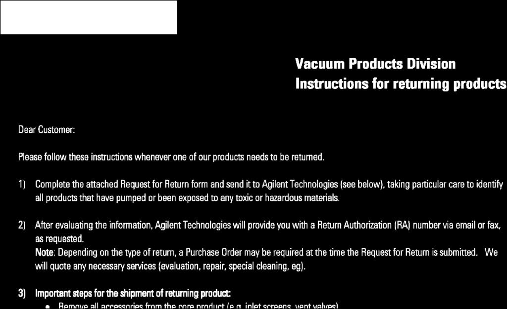
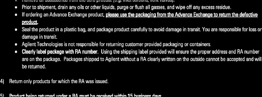
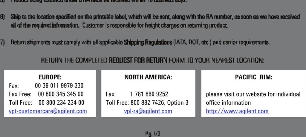
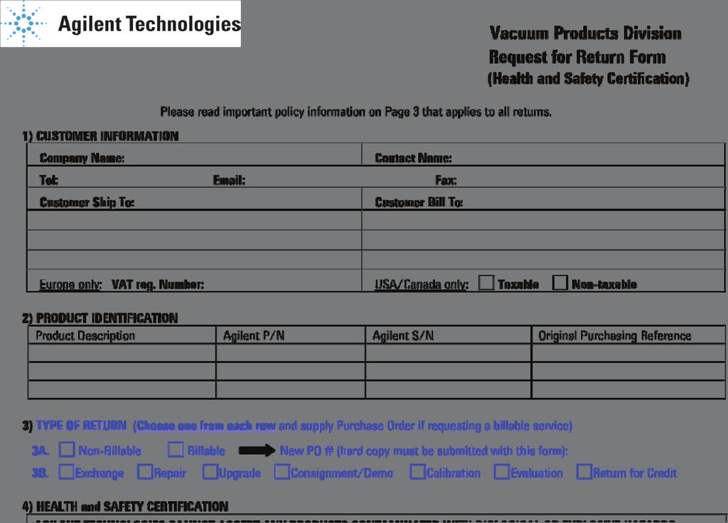
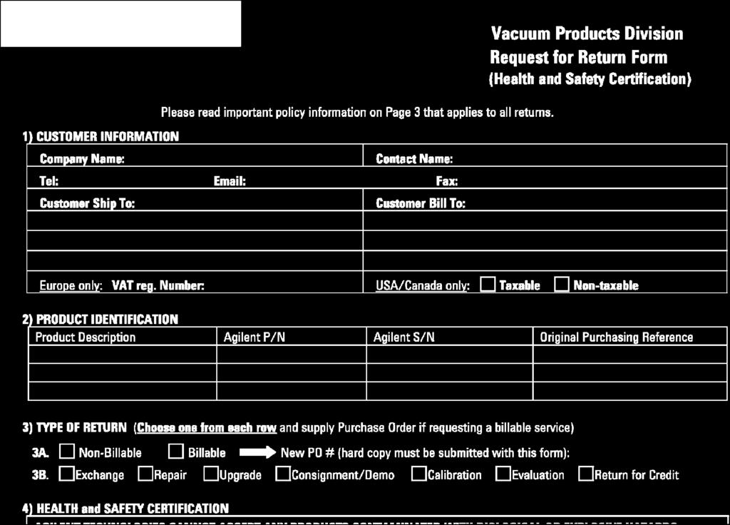
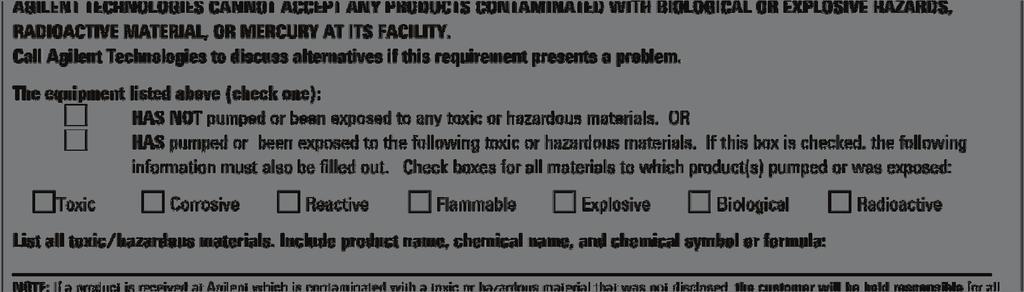
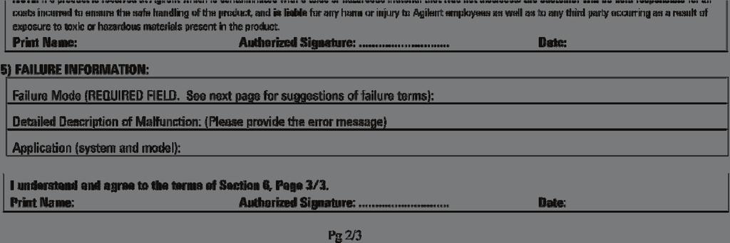
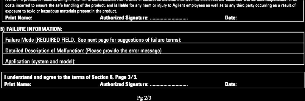
36 Request for Return Form United States Agilent Technologies Vacuum Products Division 121 Hartwell Avenue Lexington, MA USA Tel.: Fax: Toll-Free: Benelux Agilent Technologies Netherlands B.V. Vacuum Products Division Herculesweg PL Middelburg The Netherlands Tel.: Fax: Toll-Free: Canada Central coordination through: Agilent Technologies Vacuum Products Division 121 Hartwell Avenue Lexington, MA USA Tel.: Fax: Toll-Free: China Agilent Technologies (China) Co. Ltd Vacuum Products Division No.3, Wang Jing Bei Lu, Chao Yang District, Beijing, China Tel.: +86 (10) Toll-Free: France Agilent Technologies France Vacuum Products Division 7 Avenue des Tropiques Z.A. de Courtaboeuf - B.P Les Ulis cedex - France Tel.: +33 (0) Fax: +33 (0) Toll free: Germany and Austria Agilent Technologies Vacuum Products Division Alsfelder Strasse 6 Postfach Darmstadt Germany Tel.: +49 (0) Fax: +49 (0) Toll free: Sales and Service Offices India Agilent Technologies India Pvt. Ltd. Vacuum Product Division G01. Prime corporate Park, 230/231, Sahar Road, Opp. Blue Dart Centre, Andheri (East), Mumbai India Tel: /8200 Fax: Toll Free: Italy Agilent Technologies Italia S.p.A. Vacuum Products Division Via F.lli Varian Leini, (Torino) - Italy Tel.: Fax: Toll-Free: Japan Agilent Technologies Japan, Ltd. Vacuum Products Division 8th Floor Sumitomo Shibaura Building Shibaura Minato-ku Tokyo Japan Tel.: Fax: Toll-Free: Korea Agilent Technologies Korea, Ltd. Vacuum Products Division Shinsa 2nd Bldg. 2F Daechi-dong Kangnam-gu, Seoul Korea Tel.: Fax: Toll-Free: Mexico Agilent Technologies Vacuum Products Division Concepcion Beistegui No 109 Col Del Valle C.P Mexico, D.F. Tel.: Fax: Singapore Agilent Technologies Singapore Pte. Ltd, Vacuum Products Division Agilent Technologies Building, 1 Yishun Avenue 7, Singapore Tel : (65) Fax : (65) Southeast Asia Agilent Technologies Sales Sdn Bhd Vacuum Products Division Unit 201, Level 2 uptown 2, 2 Jalan SS21/37, Damansara Uptown Petaling Jaya, Selangor, Malaysia Tel : Fax: Taiwan Agilent Technologies Taiwan Limited Vacuum Products Division (3F) 20 Kao-Shuang Rd., Pin-Chen City, 324 Taoyuan Hsien, Taiwan, R.O.C. Tel Toll Free: UK and Ireland Agilent Technologies UK, Ltd. Vacuum Products Division 6 Mead Road Oxford Industrial Park Yarnton, Oxford OX5 1QU UK Tel.: +44 (0) Fax: +44 (0) Toll free: Other Countries Agilent Technologies Italia S.p.A. Vacuum Products Division Via F.lli Varian Leini, (Torino) - Italy Tel.: Fax: Toll-Free: Customer Support & Service NORTH AMERICA: Toll Free: , Option 3 vpl-ra@agilent.com EUROPE: Toll Free: vpt-customercare@agilent.com PACIFIC RIM: please visit our website for individual office information Worldwide Web Site, Catalog and Order On-line: Representative in most countries 12/10 Agilent Technologies, Inc Printed in ITALY 05/2011 Publication Number: (D)
Agilent 1290 Infinity Pump Head Maintenance
 Agilent 1290 Infinity Pump Head Maintenance Technical Note Agilent Technologies Notices Agilent Technologies, Inc. 2012-2015, 2016 No part of this manual may be reproduced in any form or by any means (including
Advanced Test Equipment Rentals ATEC (2832)
") Established 1981 Advanced Test Equipment Rentals www.atecorp.com 800-404-ATEC (2832) VS Series Leak Detectors for Vacuum Furnaces Rate of rise and vacuum decay tests will not locate leaks, they will only
Established 1981 Advanced Test Equipment Rentals www.atecorp.com 800-404-ATEC (2832) VS Series Leak Detectors for Vacuum Furnaces Rate of rise and vacuum decay tests will not locate leaks, they will only
INSTRUCTIONS. VP-100 Ion Pump. Model / R001
 INSTRUCTIONS 87-900-130-01 (A) March 3, 2011 VP-100 Ion Pump Model 819-1490 / 819-1490R001 GENERAL INFORMATION This equipment is destined for use by professionals. The user should read this instruction
The PHD-4 Portable Helium Detector. Wide range, High Performance System
 The PHD-4 Portable Helium Detector Wide range, High Performance System The Agilent Advantage Global Application Support Expertise When & Where You Need It Thousands of portable SIPD sniffing helium detectors
Agilent Auxiliary Gas Module AGM 2. User s Guide
 Agilent Auxiliary Gas Module AGM 2 User s Guide Notices Agilent Technologies, Inc. 1992, 1996, 1999, 2010 No part of this manual may be reproduced in any form or by any means (including electronic storage
Agilent Dimension Software for ELSD User Manual
 Agilent Dimension Software for ELSD User Manual Agilent Dimension Software for ELSD User Manual Agilent Technologies Notices Agilent Technologies, Inc. 2011 No part of this manual may be reproduced in
MUELLER. Mega-Lite Drilling Machine. Reliable Connections. table of contents PAGE. Equipment 2. Operating Instructions 3-4. Parts Information 5
 operating Instructions manual MUELLER Mega-Lite Drilling Machine table of contents PAGE Equipment 2 Operating Instructions 3-4 Parts Information 5 Travel Charts 6-11! WARNING: 1. Read and follow instructions
Assembly Drawing: W-311B-A01, or as applicable Parts List: W-311B-A01-1, or as applicable Special Tools: , , &
 REDQ Regulators Model 411B Barstock Design Powreactor Dome Regulator OPERATION AND MAINTENANCE Contents Scope..............................1 Installation..........................1 General Description....................1
Booster Pump PB4-60 Replacement Kits
 Booster Pump PB4-60 Replacement Kits FOR YOUR SAFETY - This product must be installed and serviced by a contractor who is licensed and qualified in pool equipment by the jurisdiction in which the product
AIR/OVER HYDRAULIC JACK 20 TON
 AIR/OVER HYDRAULIC JACK 0 TON 4487 ASSEMBLY AND OPERATING INSTRUCTIONS 349 Mission Oaks Blvd., Camarillo, CA 930 Visit our Web site at http://www.harborfreight.com Copyright 999 by Harbor Freight Tools.
Freedom8 ShoeBox Compressor Manual
 Freedom8 ShoeBox Compressor Manual Warning!! This product is not a toy! Use or misuse can cause severe injury or death! Use only with adult supervision. This unit is only to be used with tanks, hoses and
Installation, Operation, and Maintenance Manual
 Installation, Operation, and Maintenance Manual Welker Probe Instrument Regulator Model The information in this manual has been carefully checked for accuracy and is intended to be used as a guide for
Constant Pressure Crude Oil Container Model CPCCP
 Installation, Operations, and Maintenance Manual Constant Pressure Crude Oil Container Model CPCCP The information in this manual has been carefully checked for accuracy and is intended to be used as a
Series 203 Granville-Phillips Variable Leak Valve
 Series 203 Granville-Phillips Variable Leak Valve Instruction Manual Instruction manual part number 203026 Revision B - November 2016 Series 203 Granville-Phillips Variable Leak Valve Customer Service
ATS430 turbidity sensor Retractable insertion assembly
 A MEASUREMENT & ANALYTICS INSTRUCTION ATS430 turbidity sensor Retractable insertion assembly Measurement made easy 1 Introduction This publication details installation procedures for the retractable insertion
1 DRIVE INDUSTRIAL IMPACT WRENCH
 1 DRIVE INDUSTRIAL IMPACT WRENCH 92622 ASSEMBLY AND OPERATING INSTRUCTIONS 3491 Mission Oaks Blvd., Camarillo, CA 93011 Visit our Web site at http://www.harborfreight.com Copyright 2004 by Harbor Freight
THE POWERFUL LEAK DETECTOR FOR ALL APPLICATIONS IN POWER PLANTS
 THE POWERFUL LEAK DETECTOR FOR ALL APPLICATIONS IN POWER PLANTS Use of HeliTest GEN for location of leaks on the steam circuit of a turbine of a working power plant INTRODUCTION Power plant turbines, regardless
Tidland Air Chuck Installation, Operation and Maintenance
 TIDLAND WINDING SOLUTIONS Tidland Air Chuck Installation, Operation and Maintenance EN MI 517786 1 L www.maxcessintl.com Tidland Air Chuck MI 517786 1 L Page 2 CONTENTS Assembly Diagram and Parts List...
SALCO PRODUCTS, INC. PRESSURE RELIEF VALVE STORAGE, INSTALLATION, OPERATING, MAINTENANCE/TESTING, AND INSPECTION INSTRUCTIONS
 STORAGE INSTRUCTIONS Until it is time to install a new or reconditioned valve on the car, the valve must be kept in its original packaging in order to protect it from dirt and damage. INSTALLATION INSTRUCTIONS
Installation Instructions For Flat Seated Bolted Type RAH Series Disk Holders
 Installation Instructions For Flat Seated Bolted Type RAH Series Disk Holders RA Series Rupture Disks 1. WARNING a) Read the complete instructions before attempting to install the rupture disk and holder
FLANGED TWO-PIECE BALL VALVES
 INTRODUCTION This instruction manual includes installation, operation, and maintenance information for FNW flanged split-body ball valves. This manual addresses lever operated ball valves only. Please
Welker Sampler. Model GSS-1. Installation, Operation, and Maintenance Manual
 Installation, Operation, and Maintenance Manual Welker Sampler Model GSS-1 The information in this manual has been carefully checked for accuracy and is intended to be used as a guide to operations. Correct
1200B2 Series Service Regulators. Instruction Manual
 00B Series Service Regulators Instruction Manual 00B Series Service Regulators 0 Elster American Meter 00B Series Service Regulators General Information The 00B Series Service Regulators are available
FLANGED TWO-PIECE BALL VALVES
 INTRODUCTION This instruction manual includes installation, operation, and maintenance information for FNW flanged split-body ball valves. This manual addresses lever operated ball valves only. Please
Anderson Greenwood Series 93 Positive Pressure POSRV Installation and Maintenance Instructions
 Before installation these instructions must be fully read and understood Installation and maintenance instructions for Series 93 Positive Pressure Pilot Operated Safety Relief Valves (POSRV). The intent
D05T Compact Design Pressure Regulating Valves
 D05T Compact Design Pressure Regulating Valves FEATURES PRODUCT DATA Non-corroding unitized cartridge contains all working parts and is easily replaceable. Includes built-in strainer and thermal bypass.
DS06D,G Dial Set Pressure Regulating Valve
 DS06D,G Dial Set Pressure Regulating Valve PRODUCT DATA FEATURES APPLICATION Built-in, factory-calibrated outlet pressure adjustment dial. Noncorroding unitized cartridge contains all working parts and
ANDERSON GREENWOOD SERIES 9000 POSRV INSTALLATION AND MAINTENANCE INSTRUCTIONS
 Procedure-assembly-functional test and performance requirements 1 SCOPE 1.1 This document establishes the general procedure for assembly, functional testing and normal performance requirements of low Series
750 Cable Cutter INSTRUCTION MANUAL
 INSTRUCTION MANUAL 750 Cable Cutter Read and understand all of the instructions and safety information in this manual before operating or servicing this tool. Register this product at www.greenlee.com
1700ESL Kamvalok Coupler
 PART #H32138PA November 2008 1700ESL Kamvalok Coupler OPW Transport Series Dry Disconnect Couplings are considered the standard of the industry. For use on multi-compartment petroleum, solvent and chemical
TESCOM 50-4X Series Safety, Installation & Start-Up Procedures
 Operations & Service Manual TESCOM 50-4X Series Safety, Installation & Start-Up Procedures Do not attempt to select, install, use or maintain this product until you have read and fully understood this
Anti-flood device Model B-1
 December 4, 2009 Dry Systems 123a 1. DESCRIPTION The Anti-flood Device is required when Viking accelerators are installed on dry systems according to Viking Model E-1 Accelerator Trim Charts. In the SET
GE Oil & Gas Model. Masoneilan* Air Lock-up Valve Instruction Manual. GE Data Classification : Public
 GE Oil & Gas 77-6 Model Masoneilan* Air Lock-up Valve Instruction Manual GE Data Classification : Public THESE INSTRUCTIONS PROVIDE THE CUSTOMER/OPERATOR WITH IMPORTANT PROJECT-SPECIFIC REFERENCE INFORMATION
Installation, Operation & Maintenance Manual
 Original Instructions Installation, Operation & Maintenance Manual Sentry VREL Control Valve Pressure Conditioning S-SW-IOM-00277-15 1-17 Table of Contents Safety Information... 3 General Safety Precautions...
CLASS CYCLE P8000 OWNER'S MANUAL JOHNSON HEALTH TECH. CO., LTD.
 CLASS CYCLE P8000 JOHNSON HEALTH TECH. CO., LTD. No.26, Ching Chuan Rd., Taya Hsiang, Taichung Hsien 428, Taiwan, R.O.C. TEL: +886-4-2566700 FAX: +886-4-2560087 E-mail: sales@johnsonfitness.com http://www.johnsonfitness.com
1305 Series Pressure Reducing Regulators
 Instruction Manual Form 1095 1305 Series October 2009 1305 Series Pressure Reducing Regulators! Warning Fisher regulators must be installed, operated, and maintained in accordance with federal, state,
EASTERN ENERGY SERVICES PTE LTD. 60 Kaki Bukit Place #02-19 Eunos Tech Park Singapore, SG Singapore Telephone: Fax:
 2 Table Of Contents 1. Introduction 3 2. About this Manual 3 3. Contacting YZ Systems 3 4. Vessel Components 4 5. Specifications 5 6. Application 6 7. Theory of Operation 7 8. DuraSite Installation & Use
INSTALLATION, MAINTENANCE & OPERATING INSTRUCTIONS 2-4 REDUCED PORT/ FULL PORT (5700/6700) ANSI CLASS 150/300/600/900/1500/2500 TRUNNION BALL VALVES
 ANSI CLASS 150/300/600/900/1500/2500 TRUNNION BALL VALVES") PBV-USA,Inc. 12735 Dairy Ashford. Stafford, Texas USA 77477 281-340-5400; 800-256-6193 FAX: 281-340-5499 INDUSTRIAL BALL VALVES IM0 69 April 2001 Rev 9 INSTALLATION, MAINTENANCE & OPERATING INSTRUCTIONS
PBV-USA,Inc. 12735 Dairy Ashford. Stafford, Texas USA 77477 281-340-5400; 800-256-6193 FAX: 281-340-5499 INDUSTRIAL BALL VALVES IM0 69 April 2001 Rev 9 INSTALLATION, MAINTENANCE & OPERATING INSTRUCTIONS
MAINTENANCE PROCEDURE FOR X 650
 MAINTENANCE PROCEDURE FOR X 650 X 650 25. juli 2005-1/6 MAINTENANCE PROCEDURE FOR X 650 2 ND STAGE WARNING: This maintenance procedure is only for appointed Scubapro technicians that completed a course
RD(H)20/25 Pressure-Reducing Regulator User Manual
20/25 Pressure-Reducing Regulator User Manual") RD(H)20/25 Pressure-Reducing Regulator User Manual Read the complete manual before installing and using the regulator. 2 Safe Product Selection When selecting a product, the total system design must be
RD(H)20/25 Pressure-Reducing Regulator User Manual Read the complete manual before installing and using the regulator. 2 Safe Product Selection When selecting a product, the total system design must be
SKYBIRD TRAP OWNER S / OPERATOR S MANUAL PARTS AND ASSEMBLY INSTRUCTIONS
 SKYBIRD TRAP PART NO. 40903 OWNER S / OPERATOR S MANUAL PARTS AND ASSEMBLY INSTRUCTIONS WARNING: THIS MACHINE CAN CAUSE SERIOUS INJURY OR DEATH! THOROUGHLY READ INSTRUCTIONS AND SAFETY INFORMATION BEFORE
Paintball Marker. User s Manual. 530 South Springbrook Road Newberg, OR 97132
 Paintball Marker User s Manual 530 South Springbrook Road Newberg, OR 97132 Component Concepts, Inc., 530 South Springbrook Road, Newberg, OR 97132 Phone: (503) 554-8095 Fax: (503) 554-9370 www.phantomonline.com
KTM OM-2 SPLIT BODY FLOATING BALL VALVES INSTALLATION AND MAINTENANCE INSTRUCTIONS
 Before installation these instructions must be fully read and understood SECTION 1 - STORAGE 1.1 Preparation and preservation for storage All valves should be properly packed in order to protect the parts
Hydraulic Punch Drivers
 SERVICE MANUAL 7804SB / 7806SB Quick Draw 7704SB / 7706SB Quick Draw Flex Quick Draw Hydraulic Punch Drivers Serial Codes AHJ and YZ Read and understand all of the instructions and safety information in
D05 Pressure Regulating Valves
 D05 Pressure Regulating Valves FEATURES PRODUCT DATA Noncorroding unitized cartridge contains all working parts and is easily replaceable. Includes built-in strainer and thermal bypass. Balanced seat construction
4400 TwinHybrid Gas Seal
 4400 TwinHybrid Gas Seal EQUIPMENT PREPARATION MECHANICAL SEAL INSTALLATION INSTRUCTIONS 1 2 200.005" 0,13 mm 125 µ" 3,2 µm R a 3 4 32 µ" 0,8 µm R a 1000 ±.002" 0,05mm CAUTIONS These instructions are general
Type S301 & S302 Gas Regulators INTRODUCTION INSTALLATION. Scope of Manual. Description. Specifications. Type S301 and S302. Instruction Manual
 Fisher Controls Instruction Manual Type S301 & S302 Gas Regulators October 1981 Form 5180 WARNING Fisher regulators must be installed, operated, and maintained in accordance with federal, state, and local
P5513. Users Manual. Pneumatic Comparison Test Pump. Test Equipment Depot Washington Street Melrose, MA TestEquipmentDepot.
 Test Equipment Depot - 800.517.8431-99 Washington Street Melrose, MA 02176 TestEquipmentDepot.com P5513 Pneumatic Comparison Test Pump Users Manual PN 3963372 November 2010 2010 Fluke Corporation. All
Installation, Operation, and Maintenance Manual. Welker Constant Pressure Cylinder With Solid Indicator (Non-mixer) Model CP-30SI
 Model CP-30SI") Installation, Operation, and Maintenance Manual Welker Constant Pressure Cylinder With Solid Indicator (Non-mixer) Model The information in this manual has been carefully checked for accuracy and is intended
Installation, Operation, and Maintenance Manual Welker Constant Pressure Cylinder With Solid Indicator (Non-mixer) Model The information in this manual has been carefully checked for accuracy and is intended
1.0 - OPENING AND CLOSING THE DOOR
 The purpose of this manual is to provide the user with instructions on how to safely open and close, how to conduct routine maintenance, and how to install the PEI TWINLOCK Closure on a pressure vessel.
TECHNICAL DATA ANTI-FLOOD DEVICE MODEL B-1 1. DESCRIPTION
 Page 1 of 6 1. DESCRIPTION The Model B-1 Anti-flood Device is required when Viking accelerators are installed on dry systems according to Viking Model E-1 Accelerator Trim Charts. In the SET condition,
LUBRICATOR ASSEMBLY AND OPERATING INSTRUCTIONS
 AIR FILTER, REGULATOR AND LUBRICATOR 4035 ASSEMBLY AND OPERATING INSTRUCTIONS 349 Mission Oaks Blvd., Camarillo, CA 930 Visit our Web site at http://www.harborfreight.com Copyright 004 by Harbor Freight
3M Liqui-Cel EXF-10x28 Series Membrane Contactor
 Membrane Contactors 3M Liqui-Cel EXF-10x28 Series Membrane Contactor Assembly and Disassembly Instructions 3M.com/Liqui-Cel TABLE OF CONTENTS I. Safety and Warning 3 II. Assembly Parts 4 III. Part Orientation
LRS(H)4 Pressure-Reducing Regulator User Manual
4 Pressure-Reducing Regulator User Manual") LRS(H)4 Pressure-Reducing Regulator User Manual Read the complete manual before installing and using the regulator. 2 Safe Product Selection When selecting a product, the total system design must be considered
LRS(H)4 Pressure-Reducing Regulator User Manual Read the complete manual before installing and using the regulator. 2 Safe Product Selection When selecting a product, the total system design must be considered
Pressure Dump Valve Service Kit for Series 2300 Units
 Instruction Sheet Pressure Dump Valve Service Kit for Series 00 Units. Overview The Nordson pressure dump valve is used to relieve hydraulic pressure instantly in Series 00 applicator tanks when the unit
Agilent Flowmeter ADM1000
 Agilent Flowmeter ADM1000 Operating Instructions Notices Agilent Technologies, Inc. 2003 No part of this manual may be reproduced in any form or by any means (including electronic storage and retrieval
Parts: Included in the parts box: Inner Rear Tire Tray. Inner Front Tire Tray. Trail Doc Clamp. Pivot Assembly. Trail Doc Post.
 NV 2.0 2 Parts: Outer Front Tire Tray Inner Front Tire Tray Outer Rear Tire Tray Inner Rear Tire Tray Pivot Assembly Trail Doc Clamp Trail Doc Post Included in the parts box: 6mm Allen Wrench M6 Lock Washer
Installation, Operation and Maintenance Manual for Back Pressure Regulator
 Installation, Operation and Maintenance Manual for Back Pressure Regulator Model 8860 2009 Groth Corporation IOM-8860 Rev. B 12541 Ref. ID: 95565 Page 2 of 13 Table of Contents I. INTRODUCTION 3 II. DESIGN
TECHNICAL DATA CAUTION
 Page 1 of 6 1. DESCRIPTION The Viking Model D-2 Accelerator is a quick-opening device, with an integral anti-flood assembly, used to increase the operating speed of a differential type dry pipe valve.
Pressure Dump Valve Service Kit for Series 3000 Units
 Instruction Sheet Pressure Dump Valve Service Kit for Series 000 Units. Overview The Nordson pressure dump valve is used to relieve hydraulic pressure instantly in Series 00, 400, 500, and 700 applicator
User Guide. Tripod. flowtech 75 / 100 Tripod. Part No. S S
 User Guide flowtech 75 / 100 Tripod Tripod Part No. S2051-0001 S2052-0001 EN www.sachtler.com TM Copyright 2018 All rights reserved. Original Instructions: English All rights reserved throughout the world.
U S E R M A N U A L CAUTION. SAVE THESE INSTRUCTIONS Federal (USA) law restricts this device to sale by or on the order of a physician.
 law restricts this device to sale by or on the order of a physician.") U S E R M A N U A L 1600 SERIES OXYGEN REGULATOR 168715G (Shown) SAVE THESE INSTRUCTIONS Federal (USA) law restricts this device to sale by or on the order of a physician. 300 Held Drive Tel: (+001) 610-262-6090
U S E R M A N U A L 1600 SERIES OXYGEN REGULATOR 168715G (Shown) SAVE THESE INSTRUCTIONS Federal (USA) law restricts this device to sale by or on the order of a physician. 300 Held Drive Tel: (+001) 610-262-6090
USER S MANUAL QUESTIONS? CAUTION. Model No. FMEX Serial No. Write the serial number in the space above for reference. Serial Number Decal
 Model No. FMEX81110.0 Serial No. Write the serial number in the space above for reference. USER S MANUAL Serial Number Decal QUESTIONS? If you have questions, or if parts are damaged or missing, please
VL 2K LIFT D-L WINCH INSTRUCTIONS (Applies to P/Ns , , , , , )
") VL 2K LIFT D-L WINCH INSTRUCTIONS (Applies to P/Ns 3714022, 3714028, 3714034, 3714040, 3714043, 3714046) REIMANN & GEORGER CORPORATION MARINE PRODUCTS BUFFALO, NY P/N 6112103 04/09/18 1 SAFETY 1.1 INTRODUCTION
VL 2K LIFT D-L WINCH INSTRUCTIONS (Applies to P/Ns 3714022, 3714028, 3714034, 3714040, 3714043, 3714046) REIMANN & GEORGER CORPORATION MARINE PRODUCTS BUFFALO, NY P/N 6112103 04/09/18 1 SAFETY 1.1 INTRODUCTION
Eaton Raised Floor Grommets FG76, FG118. Installation Guide
 Eaton Raised Floor Grommets FG76, FG118 Installation Guide Copyright 2011 Eaton Corporation, Worcester, MA, USA. All rights reserved. Information in this document is subject to change without notice. No
Needle valve. Contents. User s Manual. (1) Be sure to read the following warranty clauses of our product 1. (2) General operating instructions 2
 Be sure to read the following warranty clauses of our product 1. (2) General operating instructions 2") Serial No. H-V024-E-7 Needle valve User s Manual Contents (1) Be sure to read the following warranty clauses of our product 1 (2) General operating instructions 2 (3) General instructions for transportation,
Serial No. H-V024-E-7 Needle valve User s Manual Contents (1) Be sure to read the following warranty clauses of our product 1 (2) General operating instructions 2 (3) General instructions for transportation,
MODEL 200 KNIFE GATE VALVES INSTALLATION & MAINTENANCE MANUAL
 MODEL 200 KNIFE GATE VALVES INSTALLATION & MAINTENANCE MANUAL Index 1. List of components / General arrangement 2. Description 3. Handling 4. Installation 5. Actuators / Operation 6. Maintenance a. Changing
BUTTERFLY VALVES Series 800
 BUTTERFLY VALVES Series 800 WARNING Before proceeding read ALL instructions and become familiar with the equipment and associated drawings. Follow ALL applicable safety regulations and codes for pressurized
Apollo Standard Port, Full Port & One Piece Flanged Ball Valves Installation, Operation, & Maintenance Manual
 I854000.D Apollo Standard Port, Full Port & One Piece Flanged Ball Valves Installation, Operation, & Maintenance Manual Introduction This manual presents guidelines for the Installation, Operation and
PRS(TC)4,8 USER MANUAL. Read the complete manual before installing and using the regulator.
4,8 USER MANUAL. Read the complete manual before installing and using the regulator.") PRS(TC)4,8 USER MANUAL Read the complete manual before installing and using the regulator. WARNING INCORRECT OR IMPROPER USE OF THIS PRODUCT CAN CAUSE SERIOUS PERSONAL INJURY AND PROPERTY DAMAGE. Due to
PRS(TC)4,8 USER MANUAL Read the complete manual before installing and using the regulator. WARNING INCORRECT OR IMPROPER USE OF THIS PRODUCT CAN CAUSE SERIOUS PERSONAL INJURY AND PROPERTY DAMAGE. Due to
Pressure Relief Valve Instruction Manual
 CVR3-M0_062017 Pressure Relief Valve Instruction Manual MODEL: CVR3 SFA Companies 10939 N. Pomona Ave. Kansas City, MO 64153 Tel: 888-332-6419 * Fax: 816-448-2142 E-mail: sales@bvahydraulics.com Website:
1800C and 1800C-HC Series Service Regulators
 1800C and 1800C-HC Series Service Regulators Installation Instructions www.elster-americanmeter.com General Information: The 1800C and 1800C-HC Regulators are available as Full Capacity Internal Relief
Retractable Hose Reel with 3/8" x 50' PVC Hose
 Retractable Hose Reel with 3/8" x 50' PVC Hose Item# 4816153 Owner s Manual Assembly and Operation Instructions MADE IN CHINA Read carefully and understand all ASSEMBLY AND OPERATION INSTRUCTIONS before
BPB26-1 AND SSPB26-1 PATIO BASE INSTALLATION INSTRUCTIONS
 BPB26-1 AND SSPB26-1 PATIO BASE INSTALLATION INSTRUCTIONS WARNING: THIS PATIO BASE IS NOT DESIGNED FOR USE WITH AN LP GAS CYLINDER. WARNING: SEE YOUR GRILL OWNER'S MANUAL FOR PROPER LOCATION, MINIMUM CLEARANCES,
Mate ULTRA IMT Multi Tool Assembly Tooling Installation Instructions
 Installation and assembly instructions for Mate ULTRA IMT Multi Tool Punch and Die Holder assemblies. 8-Station is shown. 3-Station uses the same procedure. Lubrication Port Keep top lubricated (for machine
Torque Specifications
 SENR3130-10 Torque Specifications All Caterpillar Products S/N From the library of Barrington Diesel Club CONTENT General Information 01/07/2005 Introduction to Torque 01/07/2005 Torque-Turn 01/07/2005
Right-Angle Tube Roller Model
 SPECIFICATIONS Model no. Free Speed (RPM) Throttle Rotation Max. Torque Ft-Lb Air Pressure psi Air Inlet Hose Air Flow @Free Speed Spindle Weight 909-1700 95 Lever type Reversible 240 90 1/2 NPT 1/2 I.D.
Masoneilan* 78 Model Air Filter Regulator
 GE Oil & Gas Masoneilan* 78 Model Air Filter Regulator Instruction Manual [Rev. D] GE Data Classification : Public THESE INSTRUCTIONS PROVIDE THE CUSTOMER/OPERATOR WITH IMPORTANT PROJECT-SPECIFIC REFERENCE
RS(H)10,15 USER MANUAL. Read the complete manual before installing and using the regulator.
10,15 USER MANUAL. Read the complete manual before installing and using the regulator.") RS(H)10,15 USER MANUAL Read the complete manual before installing and using the regulator. WARNING INCORRECT OR IMPROPER USE OF THIS PRODUCT CAN CAUSE SERIOUS PERSONAL INJURY AND PROPERTY DAMAGE. Due to
RS(H)10,15 USER MANUAL Read the complete manual before installing and using the regulator. WARNING INCORRECT OR IMPROPER USE OF THIS PRODUCT CAN CAUSE SERIOUS PERSONAL INJURY AND PROPERTY DAMAGE. Due to
1805 Series Relief Valves
 Instruction Manual Form 1211 1805 Series October 2011 1805 Series Relief Valves! WARNING Failure to follow these instructions or to properly install and maintain this equipment could result in an explosion
Yoke Block Instruction Manual
 Yoke Block Instruction Manual ! WARNING IMPORTANT: READ MANUAL COMPLETELY BEFORE OPERATING THIS DEVICE This manual contains instructions on periodically required checks to be performed by the user. These
DBML-60/80 Squeeze Tool
 DBML-60/80 Squeeze Tool OPERATORS MANUAL Description The Mustang Model DBML-60/80 Hydraulic squeeze tool has been manufactured since 1995. A Mustang 3 3/4 bore doubleacting cylinder producing 41,000 lbs
Helium-Oxygen Blender
 Helium-Oxygen Blender Service Manual Model No. PM5400 Series PM5500 Series (shown) SAVE THESE INSTRUCTIONS 300 Held Drive Tel: (+001) 610-262-6090 Northampton, PA 18067 USA Fax: (+001) 610-262-6080 www.precisionmedical.com
Operation and Maintenance Manual for GENTEC Model 881VR Continuous/Intermittent Digital Suction Regulators
 Operation and Maintenance Manual for GENTEC Model 881VR Continuous/Intermittent Digital Suction Regulators Genstar Technologies Co., Inc. 4525 Edison Avenue Chino, CA 91710 USA TEL 909-0-272 FAX 909-0-485
INDUSTRIAL VALVES MODELS: C62-A; C62-D. INSTRUCTION MANUAL Installation Operation Parts Service DIAPHRAGM BYPASS PRESSURE REGULATING VALVES
 INSTRUCTION MANUAL Installation Operation Parts Service IMPORTANT Record your Regulator model number and serial number here for easy reference: Model No. Serial No. Date of Purchase When ordering parts
Copyright MAY, 2008 By Grizzly Industrial, Inc. Warning: No portion of this manual may be reproduced in any shape or form without the written
 MODEL G5789/G5790 13-PIECE 3 4" IMPACT WRENCH KIT INSTRUCTION MANUAL Copyright MAY, 2008 By Grizzly Industrial, Inc. Warning: No portion of this manual may be reproduced in any shape or form without the
PARTS, SERVICE & REPAIR BULLETIN
 WH4C PARTS, SERVICE & REPAIR BULLETIN 400 SERIES HEAVY DUTY WELDING HANDLE Manual No: 0056-3763 Issue Date: October 07, 03 Revision: AA VictorTechnologies.com Table of Contents SECTION : GENERAL SAFETY
Operating Procedure TITON SUBSEA BOLT TENSIONER
 Operating Procedure TITON SUBSEA BOLT TENSIONER B & A Hydraulics Ltd Block 1, Units 1 & 2 Souter Head Industrial Centre Souter Head Road Altens Aberdeen Phone: 01224 898955 Fax: 01224 898787 E-Mail: TITON@bahyd.co.uk
Carter Option X Valve connector assembly. Maintenance manual
 Carter Option X Valve connector assembly Maintenance manual Table of contents Description Page 1.0 Introduction... 3 1.1 Safety equipment and procedure... 3 1.2 Maintenance safety alerts... 3 2.0 Equipment
299H Series. Introduction. P.E.D. Categories. Specifications. Installation. Warning. Installation Guide English September 2012
 Installation Guide English September 2012 299H Series Introduction This Installation Guide provides instructions for installation, startup, and adjustment of 299H Series regulators. To receive a copy of
Wafer Check Valve. Contents. User s Manual. (1) Be sure to read the following description of our product warranty 1
 Be sure to read the following description of our product warranty 1") Serial No. H-V066-E-3 Wafer Check Valve User s Manual Contents (1) Be sure to read the following description of our product warranty 1 (2) General operating instructions 2 (3) General instructions for
Serial No. H-V066-E-3 Wafer Check Valve User s Manual Contents (1) Be sure to read the following description of our product warranty 1 (2) General operating instructions 2 (3) General instructions for
Operating Procedures for GripTight 15.5 SDR & IPS Test Plugs
 EST Group DC2518 08/01 REV 3 12/12 Page 1 of 6 Operating Procedures for GripTight SDR & IPS Test Plugs WARNING For proper operation, GripTight plugs must be assembled as shown in Figure 1. Pressure testing
TWO POST RAM PACKAGE 5 GALLON READ THIS MANUAL CAREFULLY BEFORE INSTALLING, OPERATING OR SERVICING THIS EQUIPMENT.
 OPERATOR S MANUAL TP0411G2XXXXXXXX INCLUDING: OPERATION, INSTALLATION AND MAINTENANCE. RELEASED: 2-15-10 INCLUDE MANUALS: AF0411GXXXXXX-XX-X Two-Ball Pump (97999-1496), 66731-X Follower Assembly (pn REVISED:
Contents. Stainless Steel Side Block. 1.1 Separating the Side Block. Stainless Steel Side Block Reassembly of. Assembly from the Helmet Shell
 Separating the Side Block Assembly from the Helmet Shell Contents SSB-1 SSB-3 SSB-5 SSB-5 SSB-7 1.1 Separating the Side Block Assembly from the Helmet Shell 1.2 Side Block Assembly Replacement 1.3 Defogger
MAGNETIC INDOOR CYCLING BIKE
 MAGNETIC INDOOR CYCLING BIKE SF-B1805 USER MANUAL IMPORTANT! Please retain owner s manual for maintenance and adjustment instructions. Your satisfaction is very important to us, PLEASE DO NOT RETURN UNTIL
MUELLER. A A Adjustable. Vertical Indicator Posts. Reliable Connections. General Information 2. Technical Data 3.
 Installation Instructions manual MUELLER table of contents PAGE A-20806 A-20807 Adjustable General Information 2 Technical Data 3 Dimensions 4 Installation 5-6 Parts 7 Maintenance 8 Vertical Indicator
Installation and Service Manual
 An Actuant Company Installation and Service Manual Heavy Duty Hydraulic Stabilization Legs CONTENTS Part # 3010003129 REV 0D Section Page 1.0 Receiving Instructions 2 2.0 Safety Issues 2 3.0 Hydraulic
PROPORTIONING VALVE. Model 150 INSTRUCTION MANUAL. March 2017 IMS Company Stafford Road
 PROPORTIONING VALVE Model 150 INSTRUCTION MANUAL March 2017 IMS Company 10373 Stafford Road Telephone: (440) 543-1615 Fax: (440) 543-1069 Email: sales@imscompany.com 1 Introduction IMS Company reserves
Service and Repair Manual
 II stage R2 Ice/ Special, II stage R 1 Pro DOWNSTREAM 2 nd STAGE REGULATOR Service and Repair Manual Introduction Safety Precautions...4 General Procedures, Maintenance Schedules...5 Initial Inspection
CSA Sample Draw Aspirator Adapter Operator s Manual
 30-0951-CSA Sample Draw Aspirator Adapter Operator s Manual Part Number: 71-0367 Revision: 0 Released: 4/30/15 www.rkiinstruments.com WARNING Read and understand this instruction manual before operating