Original instructions
|
|
|
- Jasper Potter
- 5 years ago
- Views:
Transcription

1 Original instructions AVANTI SERVICE LIFT User s Manual Model Service Lift OCTOPUS L80 AT _Octopus L80 User manual EN E01R03.indd 1 10/16/2018 1:20:40 PM
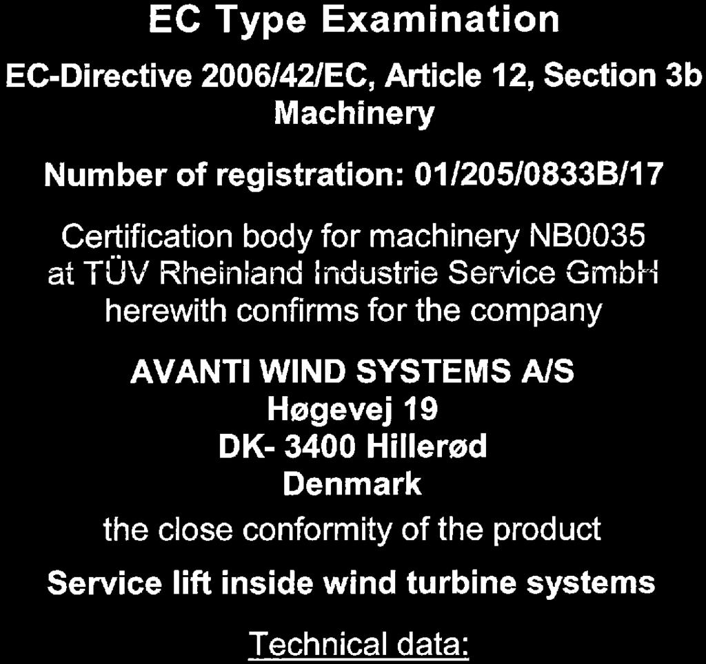


2 CE certificate for Octopus L80 AT _Octopus L80 User manual EN E01R03.indd 2 10/16/2018 1:20:40 PM

3 Date of publication: 1 st CE Edition: 09/2017 Revision 3: 15/10/2018 Manufacturer: AVANTI Wind Systems A/S Rønnevangs Allé Hillerød Denmark P: F: E: info@avanti-online.com I: Sales & Service: Australia Avanti Wind Systems PTY LTD P: +61 (0) China Avanti Wind Systems P: Denmark Avanti Wind Systems A/S P: Germany Avanti Wind Systems GmbH P: +49 (0) Spain Avanti Wind Systems SL P: UK Avanti Wind Systems Limited P: USA Avanti Wind Systems, Inc P: +1 (262) India Avanti Wind Systems India (P) Ltd P: Brazil Avanti Brasil Sistema Eólicos LTDA P: Manufactured Under Process Patent NO.8,499,896. Registered in Europe AT _Octopus L80 User manual EN E01R03.indd 3 10/16/2018 1:20:40 PM
4 Contents Page 1. Limited warranty Introduction Observations Symbols Cautions Terms and definitions Description Purpose Scope Exclusions Technical specifications Dimensions Components Overview Traction hoist Fall arrest device Traction and safety wire ropes Main control box Control boxes Platform fences Main service lift door Ladder access door Sliding window Maintenance cover Bottom hatches Top hatches Bottom obstruction device Top obstruction device Top normal limit switch Manual descent system Overload limiter Internal light Warning lights and buzzer Anchor points Rescue pendant control Information signs and documents Travelling cable pulley Fasten kit Instructions for use Daily inspection Prohibited uses Entry and exit Stop/Emergency stop Operation from inside the cabin Operation from outside the cabin Overload limiter Manual descent Fall arrest device Troubleshooting Out of service Appendix A: Daily Inspection Log Appendix B: Stomp-test Instruction AVANTI Service Lift for Wind Turbines AT _Octopus L80 User manual EN E01R03.indd 4 10/16/2018 1:20:40 PM
5 1. Limited Warranty Avanti Wind Systems A/S warrants that commencing from the date of shipment to the Customer and continuing for a period of the longer of 365 days thereafter, or the period set forth in the standard AVANTI warranty, the Product 1) described in this Manual will be free from defects in material and workmanship under normal use and service when installed and operated in accordance with the provisions of this Manual. This warranty is made only to the original user of the Product. The sole and exclusive remedy and the entire liability of Avanti under this limited warranty, shall be, at the option of Avanti, a replacement of the Product (including incidental and freight charges paid by the Customer) with a similar new or reconditioned Product of equivalent value, or a refund of the purchase price if the Product is returned to Avanti, freight and insurance prepaid. The obligations of Avanti are expressly conditioned upon return of the Product in strict accordance with the return procedures of Avanti. This warranty does not apply if the Product (i) has been altered without the authorization of Avanti or its authorized representative; (ii) has not been installed, operated, repaired, or maintained in accordance with this Manual or other instructions from Avanti; (iii) has been subjected to abuse, neglect, casualty, or negligence; (iv) has been furnished by Avanti to Customer without charge; or (v) has been sold on an AS-IS basis. Except as specifically set forth in this Limited Warranty, ALL EXPRESS OR IMPLIED CONDITIONS, REPRESENTATIONS AND WARRANTIES, INCLUDING, BUT NOT LIMITED TO, ANY IMPLIED WARRANTY OR CONDITION OF MERCHANTABILITY, FITNESS FOR A PARTICULAR PURPOSE, NON-INFRINGEMENT, SATISFACTORY QUALITY, COURSE OF DEALING, LAW, USAGE OR TRADE PRACTICE ARE HEREBY EXCLUDED TO THE MAXIMUM EXTENT PERMITTED BY APPLICABLE LAW AND ARE EXPRESSLY DISCLAIMED BY AVANTI. IF, PURSUANT TO ANY APPLICABLE LAW, TO THE EXTENT AN IMPLIED WARRANTY CANNOT BE EXCLUDED AS PROVIDED IN THIS LIMITED WARRANTY, ANY IMPLIED WARRANTY IS LIMITED IN TIME TO THE SAME DURATION AS THE EXPRESS WARRANTY PERIOD SET FORTH ABOVE. BECAUSE SOME STATES DO NOT PERMIT LIMITATIONS ON THE DURATION OF IMPLIED WARRANTIES, THIS MAY NOT APPLY TO A GIVEN CUSTOMER. THIS LIMITED WARRANTY GIVES CUSTOMER SPECIFIC LEGAL RIGHTS, AND CUSTOMER MAY HAVE OTHER LEGAL RIGHTS UNDER APPLICABLE LAWS. This disclaimer shall apply even if the express warranty fails of its essential purpose. In any cases of dispute the English original shall be taken as authoritative. 1) Avanti service lift ( Product ) User s Manual 5 AT _Octopus L80 User manual EN E01R03.indd 5 10/16/2018 1:20:40 PM
6 2. Introduction 2.1 Observations Only trained people may use this lift. This manual must be available to staff at all times during installation, maintenance and operation. Additional copies are available from the manufacturer upon request. This manual, including, but not limited to, measurements, procedures, components, descriptions, instructions, recommendations and requirements, is subject to change without prior notice. Please check Avanti website/manuals for the latest revisions of the manuals. Any additional cost related to or arising from any changes in the manuals does not entitle Customer to any form of compensation or other legal remedies.! The pictures and sketches in this manual may not reflect the product aesthetics, colours, arrangement precisely. This has no impact on the function or safety. 2.2 Symbols Symbol Signal word Meaning Possible injury if not observed Safety instructions DANGER! IMMEDIATE or possibly imminent danger: Death or severe injury! DANGER! IMMEDIATE or possibly imminent danger of hazardous voltage: Death or severe injury! CAUTION! Potentially hazardous situation: Light injury or material damage. Additional instructions! ATTENTION! IMPORTANT! Potentially dangerous situation: Useful tips for optimum working procedure Damage to equipment or workplace None Order Reference to written specification/documentation 6 AVANTI Service Lift for Wind Turbines AT _Octopus L80 User manual EN E01R03.indd 6 10/16/2018 1:20:41 PM
7 2.3 Cautions Use and daily inspection of the service lift shall only be performed by person who has gone through the relevant training associated with the Avanti service lift use and daily inspection and is in possession of a valid (non expired) certificate for the task. Installation and maintenance of the service lift shall only be performed by Certified technicians. Personnel must be at least 18 years of age. The staff must be familiar with the relevant accident prevention instructions and must have received proper training in these. Personnel are obliged to read and understand this User s Manual. Personnel shall wear PFPE (safety helmet, full body harness, shock absorber, lanyard and slider) at all times. A copy of the User s Manual must be handed out to the personnel and must always be available for reference. If more than one person is entrusted with one of the above tasks, the employer shall appoint a supervisor in charge of the operation. Electrical conection of the system must be made in accordance with EN Self-locking nuts must be used at all times. The screw must extend from the nut by at least half of the thread diameter. The nut may not be used once it has become possible to loosen by hand! If any damage or faults are found during operation, or if circumstances arise which may jeopardize safety: immediately interrupt the work in progress and notify the supervisor or employer! All tests/repairs of electrical installations may only be performed by Certified technicians. All repairs to the traction, braking and supporting systems may only be performed by Certified technicians. If any supporting parts are repaired or replaced, the operational safety of the system must be tested and verified by Certified technicians. Only original fault-free parts may be used. Use of non-original parts will render the manufacturer s warranty void and any type approval invalid. No modification, extension or reconstruction of the service lift is allowed without AVANTI s prior written consent. No warranty is provided against damage resulting from reconstruction or modification of equipment or use of non-original parts which are not approved by AVANTI. Service lift must be inspected by Certified technicians before first use. Service lift must be inspected at least once a year or after 12,5 h. of use (whichever occurs first) by Certified technicians. Service lift is designed for a lifetime of 20 years with an operating frequency of approximately 12,5 h/year (250 h in total). Service lift may not be used by persons who are under the influence of alcohol or drugs which may jeopardize working safety. The service lift shall not be used in case of fire in the tower. Service lift shall ONLY be used when the turbine is not generating power. All wind farm site specific rules must be followed. Service lift shall not be used during inclement weather, including wind speeds over 18 m/s. Avoid injury follow all instructions! Owner must verify the need for third party service lift inspections with the local authority and comply with the standards specified. 2.4 Terms and definitions Terms Certified technician User Manual descent Definitions Person who has gone through the relevant training associated with the scheduled task from Avanti or from a certified trainer and is in possession of a valid (non expired) certificate for the task. Person who has gone through the relevant training associated with the Avanti service lift use and daily inspection and is in possession of a valid (non expired) certificate for the task. Action performed to descend the lift at a controlled speed without power supply by manually opening the hoist electromagnetic brake. (Also manual no-power descent) User s Manual 7 AT _Octopus L80 User manual EN E01R03.indd 7 10/16/2018 1:20:41 PM
8 3. Description 3.1 Purpose The service lift purpose is to transport persons plus their tools and equipment to the most convenient height for performing work in wind turbine generators (WTG). Its use is limited to certified technicians. The access to the WTG and consequently to the service lift is controlled and forbidden to public access. The service lift is used primarily to transport technicians, their tools and spare parts from the bottom platform (or lowest accessible point) to the top platform (or highest accessible point). It is also used to access intermediate platforms where inspection and service of WTG connecting bolts and other equipment is made. 3.2 Scope The Octopus L80 service lift system consists of the following subsystems: Cabin. Traction and fall arrest systems. Guiding system. Control, safety and power systems (including an interlock system on platform fence doors). A rescue pendant control (only mandatory if rescue route of service lift can be somehow blocked). 3.3 Exclusions The service lift shall not be used outdoor or in potentially explosive atmospheres. The service lift is not designed to carry a person on its top. The wind turbine manufacturer is responsible of integrating the service lift and ensuring compliance with the essential health and safety requirements as stated on the 2006/42/EC Machinery Directive and the applicable harmonized standards following the manufacturer recommendations. This will require supply of interface components, including but not limited to: Ladder system. Brackets for ladder sections. Platform fences with doors. Power supply protection. The wind turbine manufacturer shall also provide any additional relevant warning, instruction and / or training specific to the integration of the service lift necessary for its safe and correct installation. Tower manufacturer s risk assessment shall include a service lift integration study. 3.3 Technical specifications Service lift Each of the subsystems listed above and their components are described in detail throughout the document. The system fully complies with essential health and safety requirements of European Machinery Directive. Main door type Main door interlock system Service lift speed Rated load Max. nº persons Max. travelling height (L80) Operating temp (normal version) Survival temperature (normal version) Operating temp (Low temp version) Max. noise level Full sliding door Trapped key / Guard locking 18 m / min ± 10 % (50 Hz) 21 m / min ± 10 % (60 Hz) 240kg 2 persons 120 m -15ºC to +60ºC -25ºC to +80ºC -25ºC to +40ºC 80 db (A) 8 AVANTI Service Lift for Wind Turbines AT _Octopus L80 User manual EN E01R03.indd 8 10/16/2018 1:20:41 PM


9 3.5 Dimensions ) ) Platform level switch location may be different due to wind turbine design. 800 User s Manual 9 AT _Octopus L80 User manual EN E01R03.indd 9 10/16/2018 1:20:41 PM

10 3.6 Components Overview Traction system 2 Fall arrest device 3 Cabin light 4 Anchor points 5 Maintenance cover 6 User control box 7 Bottom obstruction device 8 Guide ladder 9 Guiding rollers 10 Main control box 11 Hour counter 12 Ladder access door 13 Full sliding door 14 External controls 15 Top obstruction device 16 Safety wire rope 17 Traction wire rope 18 Travelling cable pulley 10 AVANTI Service Lift for Wind Turbines AT _Octopus L80 User manual EN E01R03.indd 10 10/16/2018 1:20:42 PM

 mm Kg (lbs) Octopus L80 ASL 508 500 (1100) 8.4 7 (15.4) 3.6.")
11 Traction system Fall arrest device Traction system Service Lift Hoist Lifting capacity Wire rope speed Power Rated current Traction wire rope Ø Unit weight approx. Version Traction system type Kg m/min kw A mm Kg Octopus L80 M508 / 400V 50Hz Octopus L80 M508 / 400V 60Hz Fall arrest device Service Lift Fall arrest device Lifting capacity Safety wire rope Ø Unit weight approx. Version Type Kg (lbs) mm Kg (lbs) Octopus L80 ASL (1100) (15.4) Traction and safety wire ropes Service Lift Version Wire rope type Wire rope diameter Surface Treatment Mark/ feature Min. break resistance Attached with Octopus L80 M508 / ASL mm, 5x19 HDG no 55 kn 2 t shackle User s Manual 11 AT _Octopus L80 User manual EN E01R03.indd 11 10/16/2018 1:20:42 PM
 Internal emergency stop button External UP button (for send function) External emergency stop button External DOWN button")

12 3.6.5 Main control box Hour counter Control boxes Cabin control box Trapped key switch (Optional feature. Not applicable when guardlocking system is installed) Internal emergency stop button External UP button (for send function) External emergency stop button External DOWN button (for send function) Internal UP button (for manual function) Internal DOWN button (for manual function) Platform level lamp OK lamp Overload/Warning buzzer Override key of bottom obstruction switch Fall arrest device triggered lamp Bottom platform electrical protection box Main switch 12 AVANTI Service Lift for Wind Turbines AT _Octopus L80 User manual EN E01R03.indd 12 10/16/2018 1:20:43 PM


13 3.6.7 Platform fences They must conform to EN 14122, be 1,1 m high and be equipped with doors. These must be monitored with a trapped key system that permits fence door to be opened only when service lift is present. Trapped key is attached to cabin by means of a wire rope, preventing loss of key. Optionally, the platform fences can be equipped with a guardlocking system keeping the door locked while the service lift is not at the platform. The door is unlocked when the service lift is at the platform with the lift detection switch activated. The ready light is ON when the door is closed. During emergency use, for example, power cut, need of evacuation or rescue, the door guard locking switch can be unlocked by acting the mechanical Door Manual Release system from outside the fence, or from inside the fence Main service lift door Main access to the cabin is done through the full sliding door installed on the front. The full sliding door opening dimensions are 2070 x 500 mm. It is possible to manually release guard locking system in order to open main door between platforms for maintenance tasks or installation of WTG parts. External manual release of guard locking. Internal manual release of guard locking Ladder access door Ladder access door consists of two hinged sheets that fold up when opened, thus optimizing space. In case of evacuation, the ladder access door permits direct access to ladder and ladder rail. A safety switch interrupts control when door is open. It features a guard locking system that: Prevents service lift to travel if the door is open. This opening condition is monitored by the guard locking switch. Permits door to be opened only when service lift is levelled with a platform. This levelling condition is monitored by the platform level switch which is triggered by the safe zone plates. 1) Platform level switch Safe zone plate (on all platforms) 1) Platform level switch location may be different due to wind turbine design. User s Manual 13 AT _Octopus L80 User manual EN E01R03.indd 13 10/16/2018 1:20:43 PM


14 Sliding window It consists of 2 perforated sheets that slide horizontally. The sliding window can be opened at any time. If the window is opened, a safety switch that monitors the closed function will stop the service lift. 1. Perforated sheets 2. Window switch 1 2 Direct evacuation to ladder is possible at any position along the WTG. The sliding window shall not be used for accessing or exiting the cabin! During the manual descent, the doors, window and hatches of the lift shall be kept closed. Don not extend body parts outside the cabin during travel Maintenance cover Maintenance cover allows safe and fast inspection of traction and safety wire ropes from inside the cabin while travelling Top hatch Top hatch can be opened from both sides, thus allowing egress and ingress from above. It has a safety switch that interrupts control when hatch is opened. Top obstruction device hatch opens outwards. Once top hatches and ladder access door are open, clear area is at least 500 x 500 mm, and ladder becomes totally accessible Bottom hatches Bottom hatches can be opened from both sides, thus allowing egress and ingress from underneath. Bottom cabin hatch opens inwards, and bottom obstruction device hatch opens outwards. Each of them has a safety switch that interrupts control when hatch is opened. Once top hatches and ladder access door are open, clear area is at least 500 x 500 mm, and ladder becomes totally accessible Bottom obstruction device Bottom obstruction device interrupts descent if: It encounters an obstacle. It reaches the bottom platform. Ascent will still be possible, for instance to remove the obstacle. In order to put the service lift on the ground, the contact plate functionality can be bypassed with the override bottom obstruction device switch located on the cabin control box. To do so, turn the override bottom obstruction switch key while pressing the down button. Release the DOWN button as soon as the rubber bumpers hit the floor. Otherwise the service lift or the installation may get damaged. 14 AVANTI Service Lift for Wind Turbines AT _Octopus L80 User manual EN E01R03.indd 14 10/16/2018 1:20:43 PM


15 A mechanical bottom obstruction device switch permits the bottom obstruction device to be still operational during manual descent. Manual descent will be stopped if an obstacle is encountered Top limit switch Top limit switch interrupts ascent if it is triggered by the top plate. Emergency top limit switch is triggered in case the top limit switch fails to engage. It cuts off power supply, so only manual descent will be possible. These switches are located on the top of the cabin, beside safety and traction wire ropes. Top limit plate is mounted attached to traction and safety wire ropes. Top limit plate Guiding shaft & supporting wire Bottom obstruction switches Guiding shaft & supporting wire Bottom obstruction device (plate) Mechanical bottom obstruction device switch Top obstruction device Top obstruction device interrupts ascent if it encounters an obstacle. Descent will still be possible, for instance to remove the obstacle.! Guiding shafts with spring (x4) When the top obstruction device switches are engaged, press the down button until it disengages. Do not use the service lift until the top obstruction device switch fault has been rectified. Top obstruction switches Top obstruction device (plate) Manual descent system The service lift features a manual descent system that can be used in case of emergency. To activate it, push the manual descent actuator fully upwards. The electromagnetic motor brake is released. The service lift descends with a controlled speed limited by means of a centrifugal brake installed between the motor shaft and the gear box Overload limiter An overload limiter is built into the traction hoist. In case of an overload, it will prevent the upward travel and a buzzer will sound, until overload condition is eliminated. Attempting to run in an overloaded lifif is prohibited! Performing a manual descent in case of an overloaded lift is prohibited! User s Manual 15 AT _Octopus L80 User manual EN E01R03.indd 15 10/16/2018 1:20:44 PM


16 Internal light The service lift is equipped with a light inside the cabin. When service lift is connected to power supply, this light illuminates at all times. The internal light is battery packed in order to illuminate the inside of the cabin in case of a power failure. When fully charged, it will last at least for 90 minutes Warning lights and buzzer A set of warning lights is mounted on the top and on the bottom of the service lift. The flashes warn that the service lift is moving Rescue pendant control Rescue pendant control is only mandatory if rescue route of service lift can be somehow blocked. A blocked rescue route is an event where: A person is unconscious inside the service lift, blocking the bottom hatch, the rescuer is below service lift, and the service lift is stopped halfway through a platform hole, blocking rescue route since platform has no extra hatch. When actuating the external UP or DOWN buttons, response of cabin is delayed while the warning lights are flashing and the warning buzzer sounds, in order to warn personnel in the surroundings that cabin is going to move.! There shall be one rescue pendant control per WTG; and it shall be stored in the WTG bottom platform. A clearly visible sign shall indicate its exact location. It features three buttons: UP, DOWN and emergency stop button. When necessary, pendant control is plugged to cabin bottom socket. It has a 4 m long cable that permits service lift to be powered up/down that same distance. When plugged, pendant control does not override any safety switch. If any of them is triggered, no running will be possible; including the obstruction device switches. Therefore, there is no risk of moving service lift hitting rescuer. Pendant control overrides cabin control box, and service control box if installed. Overload/Warning buzzer Anchor points The service lift features two anchor points inside the cabin. Each anchor point may only be used by one user simultaneously. During operation personnel must hook themselves up to the anchor points inside the cabin, in order to prevent falling risks. In case of need of evacuation, the evacuation procedure will be followed. 16 AVANTI Service Lift for Wind Turbines AT _Octopus L80 User manual EN E01R03.indd 16 10/16/2018 1:20:44 PM


 Remove eye nuts stickers Pull to open sticker (ladder door) Evacuation guide Wiring diagram Electrical hazard warning label Rescue pendant control emergency sign 3.6.")

17 Information signs and documents The manual and quick guide are accessible from inside the cabin. The following documents, signs and labels are supplied with the service lift and shall always be available. A rescue pendant control emergency sign shall be present at the bottom platform, clearly indicating storage location of rescue pendant control. Location Cabin Main control box Bottom platform Document Serial number plate Manual documents inside blue bag Quick guide document Use of PFPE label sign Working load limit / Nº persons label Manual descent label Fall arrest deactivation label Fall arrest activation label Main door guardlocking labels No standing on top prohibition label Fasten kit sticker For one person only sticker (anchor point) Remove eye nuts stickers Pull to open sticker (ladder door) Evacuation guide Wiring diagram Electrical hazard warning label Rescue pendant control emergency sign Travelling cable pulley Travelling cable is connected from power supply socket over mid tower s height platform to service lift socket and it is provided with a cable relief on each end. A travelling cable pulley is suspended on the cable and is guided along the traction and safety wire ropes. The travelling cable pulley straightens the cable at all times Fasten kit The service lift features an special tool, called Fasten kit, for mechanically blocking the lift in order to perform installation/maintenance tasks below the suspended cabin. This kit is located inside the cabin. It consists in a M16 screwed rod, that must be inserted through a hole of the top rollers assembly and along a rung of the guiding ladder, and finally blocked with a M16 nut. Fasten kit M16 nut Travelling cable M16 screwed rod Travelling cable pulley Traction wire rope Safety wire rope User s Manual 17 AT _Octopus L80 User manual EN E01R03.indd 17 10/16/2018 1:20:45 PM
18 4. Instructions for use 4.1 Daily inspection Daily inspection of the service lift shall only be performed by the user. If there is more than one user, the employer shall appoint a supervisor in charge of the daily inspection Overall Visual Inspection: a) Check that the cabin has no damages. b) Check that the top and bottom obstruction devices are free of damages. c) Check that the traction and safety wire rope ropes are correctly fed and guided. d) Record the hour counter reading on the Daily Inspection Log Appendix Travel zone a) Ensure that there are no obstacles within the service lift s operating area which may obstruct the travel of the cabin or cause the cabin to hit the ground Control and safety devices Cabin control from inside the cabin a) Close the doors. Press the EMERGENCY button. The lift should remain still when the UP/DOWN button is pressed. To restart, pull the EMERGENCY button. b) Test the EMERGENCY top limit switch: During upward travel, press the switch manually, and the service lift shall stop immediately. Neither upward nor downward travel should now be possible. c) Bottom obstruction device. Lower the lift; It shall stop before the rubber feet of the cabin reach the tower ground level. d) Door switch: Open the door it shall not be possible to move the lift upwards or downwards. Place the cabin at a height no corresponding to platform it shall not be possible to open the door. The door is only able to open by turning the emergency release lever up. f) Top obstruction device: activate device by pressing it down. The service lift shall not move up until device is released.! If any faults occur during work, - stop working, - if required secure the workplace and - rectify the fault! Make sure that nobody is exposed to danger below the service lift, for instance from falling parts. g) Fall arrest device. Activate the fall arrest device by pulling down the red locking handle. Press and hold the DOWN button of the cabin control box. The service lift should not descend. Try to perform manual descent. The service lift should not descend. Press and hold the UP button of the cabin control box. The service lift should ascend. Unlock the fall arrest device by pulling down the black unlocking handle. There is a supplementary method to check the FAD functionality, called Stomp Test. The procedure is explained in the Stomp-test Instruction Appendix Cabin control from outside of the cabin Automatic send The automatic mode function is only available from the control buttons outside of the cabin and shall be checked as follows: a) Press the UP button. The warning lights start flashing and the warning buzzer will sound. Once the delay time response of cabin is finished, the service lift should travel upwards. b) Press the EMERGENCY button on the control box. The lift stops. c) Pull the EMERGENCY button and press the DOWN button. The warning lights start flashing and the warning buzzer will sound. Once the delay time response of cabin is finished, the service lift should travel downwards until the bottom obstruction device engages. e) Key switch ON/OFF (if installed): Turn the key to OFF it shall not be possible to move the lift upwards or downwards. 18 AVANTI Service Lift for Wind Turbines AT _Octopus L80 User manual EN E01R03.indd 18 10/16/2018 1:20:45 PM

19 4.2 Prohibited uses The consequences of not following below prohibitions are extremely hazardous to the physical integrity of the users. When using the service lift it is prohibited to: Use the service lift beyond its intended purpose. Operate the service lift without following the safety warnings and operating instructions. Overload the service lift more than its rated load. Try to repair machine components. Only certified technicians are allowed to perform service on the machine. To use the ladder while service lift is being used. To use the ladder, unless service lift is out of service, or in case of evacuation or rescue. To manipulate switches and safeties. To place objects on service lift roof. To travel on service lift roof. To use the emergency manual release of the guard locking of door lift or fence doors during normal use. To disattach trapped key from wire rope. To have a second trapped key. - Turn the override bottom obstruction device switch clockwise and hold. - Press the DOWN button until the service lift rests on the floor, then release. 4.6 Operation from outside the cabin (automatic send configuration) Transportation of people is forbidden if the operation is controlled from outside the cabin Operation by means of the user control box: a) The key switch ON/OFF should be ON (if available). b) Close the door. c) Press the UP or DOWN button respectively and the cabin starts ascending/descending. 4.3 Entry and exit To ensure safe entry and exit: a) Lower the service lift onto the access platform until the bottom obstruction device is activated and the cabin stops, or: bring the lift to a height corresponding to the correct level for exiting from the wind turbine s platform. b) Open the door and exit/enter the lift through the door. 4.4 Stop/Emergency stop a) Release the Up or Down button; the service lift should stop. If it does not: b) Push the EMERGENCY button, and all controls should be disabled. 4.5 Operation from inside the cabin! Transportation of people is forbidden if the operation is controlled from outside the cabin When actuating the external UP or DOWN buttons, response of cabin is delayed while the warning lights are flashing and the warning buzzer sounds, in order to warn personnel in the surroundings that cabin is going to move. Before closing the lift door, ensure that your equipment (i.e.lanyards) do not get trapped/ tangled with the closing door and/or with surrounding elements. To prevent the lanyards from tangling with surrounding elements, keep them properly attached to your body harness. To prevent the lanyards from tangling with the moving service lift, do not get close to the hoistway. a) Close the door b) The key switch ON/OFF should be ON (if available) c) To go up or down, push and hold the Up or Down button. d) To place the service lift on the floor after the bottom obstruction device has stopped the lift. User s Manual 19 AT _Octopus L80 User manual EN E01R03.indd 19 10/16/2018 1:20:45 PM
 Remove enough of the load to make the buzzer stop and enable upward travel.")

20 4.7 Overload limiter a) In case of an overload, the lift s upward travel should be blocked, and a buzzer should sound in the connection cabinet. Attempting to run in an overloaded lift is prohibited! Performing a manual descent in case of an overloaded lift is prohibited! b) Remove enough of the load to make the buzzer stop and enable upward travel.! On entering and starting the lift, the buzzer may sound briefly. This is due to temporary load peaks occurring as the lift takes off. The overload limiter is designed not to activate the buzzer or stop the lift because of peak loads caused by the cabin swinging. If the problem persists have a certified technician adjust the overload limiter (Refer to Regulation of overload limiter Appendix in Installation and Maintenance Manual). 4.9 Fall arrest device To lock the fall arrest device in an emergency: Pull down the red handle. If the fall arrest device engages, simply disengage it from inside the cabin until the fall arrest device is unlocked by: Pulling the black handle downwards. However, this is not possible if the safety wire rope is under tension. If this is the case: 1. Remove the load on the safety wire rope by pushing the UP button taking the lift upwards a few centimetres. 2. Manually open the fall arrest device until the fall arrest device is unlocked by: Pulling the black handle downwards. In case of no power and the fall arrest device is locked with the safety wire rope under tension evacuate the lift according to the Evacuation guide. 4.8 Manual descent If a power failure or an operation fault etc. interrupts the hoist, a manual descent is possible from inside the cabin. 1. The lever is attached underneath the cabin top. Turn it down. 2. Push the lever upwards the full way. The service lift moves downwards. The built-in mechanical overspeed limiter limits the pace of descent. 3. To stop, simply loosen the lever. 4. After manual descent, the system must be 5. checked by a certified tecnician. Brake release lever. During the manual descent, the doors, window and hatches of the lift shall be kept closed. Don not extend body parts outside the cabin during travel. PULL TO UNLOCK (Black) PULL TO LOCK (Red)! During manual descent if the bottom obstruction device hits an obstacle, the brake release lever is mechanically disengaged so the further descent is disabled. The system is automatically reset once the obstacle is removed. 20 AVANTI Service Lift for Wind Turbines AT _Octopus L80 User manual EN E01R03.indd 20 10/16/2018 1:20:45 PM
21 4.10 Troubleshooting 1. All tests and repairs to the electronic components should be performed by certified technicians only! The wiring diagram is placed in the power cabinet. 2. Repairs to the traction hoist, the fall arrest device and to the system s supporting components should be performed by certified technicians only! Breakdown Cause Solution The service lift will neither go up nor down! DANGER! Attempting to use the lift will jeopardize work safety. A1 The fixed EMERGENCY button has been activated. Deactivate the button in question by pulling it until it pops out. DANGER! Unplug the power supply before opening the power cabinet. A2 Wire rope loop on traction hoist. Damaged or defective wire rope or wire rope outlet causes problems. A3 The fall arrest device is holding the service lift on the safety wire. a) Lift wire rope breakage b) Hoist failure A4 The service lift is stuck on an obstacle. A5 Power failure a) Control not switched on or deactivated. b) Grid voltage interrupted. c) Supply between grid connection and control interrupted. d) Phase control relay tripped due to wrong phase sequence. A6 Safety switch is triggered a) EMERGENCY top limit switch was pressed. b) Door switch is not properly closed or is defective. c) Ladder access door switch is activated. d) A top or bottom hatch switch is triggered. A7 Protection switch on overheating a) A phase is missing b) Motor is not cooling c) Voltage too high/low A8 Brake does not open (no click on on/off) a) Supply, braking coil or rectifier defective. b) Braking rotor closes. Stop work immediately! Ask the supplier or manufacturer for help. a) + b) Evacuate the service lift according to the Evacuation guide. Carefully remove the obstacle. Test the operational safety of affected tower sections. Inform the supervisor. a) Turn EMERGENCY button to the right until it is released. b) Find the cause and wait for the power to return. c) Test and if necessary repair the supply cable, fuses, and/or wiring from the control box. d) Check and correct phase lay at power supply. a) Perform manual descent until the emergency top limit switch is released. b) Close the door and test the door switch. c) Close the door. d) Close the hatch. a) Test/repair fuses, supply and connection. b) Clean the hood. c) Measure voltage and power consumption on the loaded motor. If voltage deviates from specifications, use cable with increased dimensions. a) Have a certified technician, repair/replace the supply, braking coil and rectifier. b) Return traction hoist for repair. User s Manual 21 AT _Octopus L80 User manual EN E01R03.indd 21 10/16/2018 1:20:45 PM
22 Breakdown Cause Solution The service lift will neither go up nor down Service lift goes down but not up DANGER! Unplug the power supply before opening the power cabinet. A9 The key switch ON/OFF has not been activated (if installed). A10 The main switch is in the OFF position. A11 Rescue pendant control is plugged. Irresponsible behaviour jeopardizes system safety! B1 The service lift is stuck on an obstacle. B2 Overload Buzzer sounds in the connection cabinet. B3 Top obstruction / top limit switch: a) Top obstruction / top limit switch is defective or not connected properly b) Top obstruction / top limit switch is activated. B4 A phase is missing B5 Fault in UP control circuit in control box or traction system Turn the key to ON. Turn the main switch ON. - Use rescue pendant control in case of rescue event. - Otherwise, unplug pendant control. Carefully move the service lift downwards and remove the obstacle. Test the operational safety of affected platform components. Inform the supervisor. Test and possibly reduce load until buzzer stops. a) Test the top obstruction / top limit switch connection/function. Replace it if necessary. b) Descend the service lift until the top obstruction / top limit switch is released. Test fuses and power supply. Test and possibly repair connections, wiring and relays. Motor hums loudly or wire ropes squeak, but the lift can go both up and down. C1 Wire ropes dirty! WARNING! Further use of lift may result in damage to the wire rope traction. If possible, immediately replace the traction system and return it for test/repair at AVANTI. 22 AVANTI Service Lift for Wind Turbines AT _Octopus L80 User manual EN E01R03.indd 22 10/16/2018 1:20:46 PM
23 Breakdown Cause Solution Service lift will go up but not down! DANGER! Unplug the power supply before opening the power cabinet. OK lamp not lit although operation is normal. Loud noise and / or smoke coming from hoist motor Irresponsible behaviour jeopardizes system safety! D1 The service lift has encountered or is stuck on an obstacle. D2 The fall arrest device is holding the service lift on the wire rope. a) Excessive hoist speed b) Too low release speed on fall arrest device. A defective fall arrest device will threaten the safety of the service lift! Replace immediately! D3 Fault in down controller circuit on traction system D4 Bottom obstruction switch: a) Bottom obstruction switch is defective or not connected properly. b) Bottom obstruction switch is activated. E A lamp is defective F Brake closed or partially closed WARNING! Damage of hoist brake leading to brake function lost Carefully take the service lift up and remove the obstacle. Test the operational safety of affected platform components. Inform the supervisor. a) + b) Take the service lift upwards to relieve the safety wire rope. Unlock the fall arrest device by turning the unlocking lever, and test its function. Functional test when the lift is back on the ground: Replace the hoist and fall arrest device and return them for testing. Insert brake lever into the traction system and lower lift manually. Test, and if necessary have connections, wiring, and relays repaired. a) Test the bottom obstruction switch connection/function. Replace if necessary. b) Move lift up until the bottom obstruction switch is released. Have an electrician replace it. Stop work immediately! Call supervisor for advice and potential repair of hoist If these steps do not identify the cause and rectify the fault: Consult a certified technician or contact the manufacturer Out of service 1. Securing the service lift: Bring the service lift all the way down, until the bottom obstruction device stops the cabin. 2. Turn off the main switch to prevent inadvertent operation of the lift: Turn the main switch to the OFF position Power supply is now interrupted. Mark the lift OUT OF SERVICE. Contact the service technician for repair. User s Manual 23 AT _Octopus L80 User manual EN E01R03.indd 23 10/16/2018 1:20:46 PM
24 Appendix B: Stomp-test Instruction Supplementary way to inspect the ASL during Daily Inspection before Operation Purpose This instruction is a supplementary part of the Daily Lift Checking to be used by authorized users and Certified technicians. The information describes a recommended and supplementary way of how to check the over speed triggering and arresting function in the Avanti Safety Fall Arrest Device model ASL. Second, the test also documents that the Safety Brake maintains its grip on the Safety Wire after engagement. This extra testing we name the Stomp-test. This stomp-test-method is supplementary to the given daily obligation in your manual explaining to descend the lift, manually engage the FAD (Fall Arrest Device), verification by short no-powerdescent, unloading the FAD again by ascending and observing centrifugal weigh unit through the window during lift use. With the Stomp-test we test the ability of the FAD to trigger in case of over speed and arrest the load. Tools: None Measurement Equipment: None Validity It is applicable for testing the installed Safety Fall Arrest Device (ASL) on-site. The test must only be performed by trained users/certified technicians and always with respect of all the relevant safety regulations. Cautions Be aware that the instruction only explains the steps of how to execute the Stomp test in the lift installation; it doesn t guide any safety precautions and the necessary use of safety equipment. Therefore, Avanti strongly recommends you to read and understand what the physical work steps in the Stomp-test are, and then execute your own Risk and Hazard Assessment according to the valid safety working procedures in your own organisation before starting the test. 1. Test Preparation The cabin (with 1 person inside) is ascended with a service lift user inside, and the cabin bottom is positioned ( parked ) in a height of app. 3 m/10 ft. above the bottom landing floor platform. 2. Test Step With the cabin in parked position app. 3 m/10 ft. above the bottom landing floor, the user starts descending by electrical power using the push down button. When the cabin starts descending the user executes a hard stomp with one foot in the cabin floor The hard stomp is executed by lifting one foot, so the lower leg is positioned with a knee angle of 90 degrees Then immediately after the foot is stomped in the cabin floor - The user must make sure to have a solid footing during the foot stomp! The foot stomp should engage the ASL and arrest the electrical descent of the cabin, the red light (if existing in the control box) should turn on and the cabin load should be hanging on the FAD/Safety Wire. If the ASL doesn t arrest at the first trial, then reestablish the cabin in the position described in the preparation part mentioned above and execute the Step once again stomping a little harder. 3. Test Result If the ASL activates properly after the stomp, the ASL will now hold the cabin on the Safety Wire. In order to ensure important maintaining grip by the Safety Brake, the user then activates the manual descent function and result shall be a Safety Fall Arrest Device ASL holding the cabin fixed on the Safety Wire (manual descending is not possible). - If the activated ASL fixes the cabin on the Safety Wire while manual descent is activated, the Safety Fall Arrest Device (ASL) is in good and operational condition. In order to release the activated ASL push the ascent button up a little before releasing the ASL by the unlocking handle. - If the ASL can t activate after first or second Stomp-test, or can t fix the cabin in activated position - User must immediately bring the cabin down and park it at the bottom landing platform floor. - Lock Out the installation from use and contact Avanti for further approach! - Document the execution of the above described procedure in the Daily Inspection Log Appendix. Any doubts regarding above instruction, please do not hesitate to contact Avanti s local representative for help AVANTI Service Lift for Wind Turbines AT _Octopus L80 User manual EN E01R03.indd 34 10/16/2018 1:20:47 PM
25 User s Manual 35 AT _Octopus L80 User manual EN E01R03.indd 35 10/16/2018 1:20:47 PM
26 Australia Avanti Wind Systems PTY LTD Unit 7 / 109 Tulip Street, Cheltenham Melbourne VIC 3192 P: +61 (0) China Avanti Wind Systems Building 4, No, 518, Gangde Road, XiaokunshanTown Songjiang District, Shanghai P: F: Denmark Avanti Wind Systems A/S Rønnevangs Allé 6 DK-3400 Hillerød P: F: Germany Avanti Wind Systems GmbH Max-Planck-Str Elmshorn P: +49 (0) F: +49 (0) Spain Avanti Wind Systems SL Poligono Industrial Centrovia Calle Los Angeles No 88 nave La Muela P: F: UK Avanti Wind Systems Limited Unit 2, Cunliffe Court Clayton-Le-Moors Accrington BB5 5JG P: +44 (0) AT Octopus L80 User s manual, EN 1st CE Edition: 09/2017 Revision 3: 15/10/2018 USA Avanti Wind Systems, Inc West Forest Home Ave. Franklin, Wisconsin P: +1 (262) F: +1 (262) India Avanti Wind Systems India (P) Ltd. Old No. 28, New No. 41, Vellala Street, Aiyanambakkam Chennai Tamil Nadu P: Brazil Avanti Brasil Sistema Eólicos LTDA. Rua João Paulo II, 131 Autódromo Eusébio, Ceará P: AVANTI Service Lift for Wind Turbines I: E: info@avanti-online.com AT _Octopus L80 User manual EN E01R03.indd 36 10/16/2018 1:20:47 PM
Original instructions
 Original instructions AVANTI SERVICE LIFT User s manual Model Service Lift SWP XL 02 ate of publication: 2nd Edition: July 2017 Revision 3a: 17/12/2018 This manual covers products with Serial numbers from
AVANTI ANCHOR SAFETY POINT User s, Maintenance and Installation Manual
 Original instructions 1 AVANTI ANCHOR SAFETY POINT User s, Maintenance and Installation Manual AVANTI ANCHOR SAFETY POINT User s Manual and Installation Instructions Date of publication: 2 nd Edition:
2000 lb manual winch
 2000 lb manual winch Model 41694 Operation Instructions Due to continuing improvements, actual product may differ slightly from the product described herein. 3491 Mission Oaks Blvd., Camarillo, CA 93011
blocstop BSO 500 and BSO 1000 series Fall arrest device for suspended man-riding installations Assembly and Operating Instructions
 blocstop BSO 500 and BSO 1000 series Fall arrest device for suspended man-riding installations Assembly and Operating Instructions G671_BA_BSO5_10_US.pm6 GREIFZUG GmbH 03/2007 Griphoist Division www.tractel.com
RESCUE LIFTING DEVICE RUP 503-[...] AT 053-[...] xx
![RESCUE LIFTING DEVICE RUP 503-[...] AT 053-[...] xx](/thumbs/90/102827869.jpg "RESCUE LIFTING DEVICE RUP 503-[...] AT 053-[...] xx") EN 1496:2006 / B Reference number: RESCUE LIFTING DEVICE RUP 503-[...] AT 053-[...] xx DESIGNATED USE The rescue lifting device RUP 503-[...] series is a component of rescue system. Using this device the
EN 1496:2006 / B Reference number: RESCUE LIFTING DEVICE RUP 503-[...] AT 053-[...] xx DESIGNATED USE The rescue lifting device RUP 503-[...] series is a component of rescue system. Using this device the
Overspeed governors (113 OG Моment 250 MR, 114 OG Moment 250 A3, 115 OG Moment 250 MRL, 119 OG Moment 250 MRL/1)
") Overspeed governors (113 OG Моment 250 MR, 114 OG Moment 250 A3, 115 OG Moment 250 MRL, 119 OG Moment 250 MRL/1) Instructions for installation and operation 113 OG Моment 250 MR 115 OG Moment 250 MRL Overspeed
Overspeed governors (113 OG Моment 250 MR, 114 OG Moment 250 A3, 115 OG Moment 250 MRL, 119 OG Moment 250 MRL/1) Instructions for installation and operation 113 OG Моment 250 MR 115 OG Moment 250 MRL Overspeed
PPS PORTABLE POWER SUPPLY
 PPS User Manual Rev 1-2015 ENG MASTER PPS PORTABLE POWER SUPPLY Disclaimer About ActSafe Safety messages and warnings Product safety System description Pre-use inspection and connection General safety
GM-120: Container Top Lock Anchor Wand Page 1 WINSAFE CORP. GM 120 CONTAINER TOP LOCK ANCHOR WAND OPERATING INSTRUCTIONS AND MAINTENANCE
 GM-120: Container Top Lock Anchor Wand Page 1 WINSAFE CORP. GM 120 CONTAINER TOP LOCK ANCHOR WAND OPERATING INSTRUCTIONS AND MAINTENANCE US Patent No. 6834745 This equipment conforms to 0321 EN795:1996
DBI SALA Confined Space Rescue Davit System
 Instructions for the following series products: Rescue Davit System (See back page for specific model numbers.) User Instruction Manual For Davit Rescue System This manual should be used as part of an
GM-121: Container End Lock Anchor Wand Page 1 WINSAFE CORP. GM 121 CONTAINER END LOCK ANCHOR WAND OPERATING INSTRUCTIONS AND MAINTENANCE
 GM-121: Container End Lock Anchor Wand Page 1 WINSAFE CORP. GM 121 CONTAINER END LOCK ANCHOR WAND OPERATING INSTRUCTIONS AND MAINTENANCE US Patent No. 6834745 This equipment conforms to 0321 EN795:1996
SpanSet Gotcha CRD User Instructions. SpanSet Certified Safety
 SpanSet Gotcha CRD User Instructions SpanSet Certified Safety 1 Table of contents Description 3 Preparation 4 Rescue of casualties 4 Alternatives for recovering the rescuer 5 Storage and transportation
NIHON BISOH CO., LTD.
 BISOMAC210 Electric Traction Hoist Operator s Manual North American Model with Overload Detection Device NIHON BISOH CO., LTD. IMPORTANT SAFETY INSTRUCTIONS READ ALL INSTRUCTIONS BEFORE USING THIS TRACTION
NIHON BISOH CO., LTD.
 BISOMAC210 Electric Traction Hoist Operator s Manual Model: BISOMAC210-1000 NIHON BISOH CO., LTD. IMPORTANT SAFETY INSTRUCTIONS READ ALL INSTRUCTIONS BEFORE USING THIS TRACTION HOIST. Failure to follow
User Instruction Manual For Davit Rescue System
 Instructions for the following series products: Rescue Davit System Model numbers 8004000 and 8302500 User Instruction Manual For Davit Rescue System This manual should be used as part of an employee training
BRAKE WINCH RUP 503-[T/BT] EQUIPMENT FOR LIFTING LOADS. AT 053-[T/BT] xx
![BRAKE WINCH RUP 503-[T/BT] EQUIPMENT FOR LIFTING LOADS. AT 053-[T/BT] xx](/thumbs/88/115945274.jpg "BRAKE WINCH RUP 503-[T/BT] EQUIPMENT FOR LIFTING LOADS. AT 053-[T/BT] xx") Reference number: BRAKE WINCH RUP 503-[T/BT] EQUIPMENT FOR LIFTING LOADS DESIGNATED USE The brake winch RUP 503-[...]T series is a load lifting / lowering device. Device is equipped with safety brake for
Reference number: BRAKE WINCH RUP 503-[T/BT] EQUIPMENT FOR LIFTING LOADS DESIGNATED USE The brake winch RUP 503-[...]T series is a load lifting / lowering device. Device is equipped with safety brake for
Operating instructions Safety Rope Emergency Stop Switches ZB0052 / ZB0053 ZB0072 / ZB0073
 Operating instructions Safety Rope Emergency Stop Switches UK ZB0052 / ZB0053 ZB0072 / ZB0073 7390878 / 02 03 / 2011 Contents 1 Safety instructions...3 2 Installation / set-up...4 2.1 Applications...4
VL PONTOON/TRITOON DECK BRACKET 13 INSTRUCTIONS
 VL PONTOON/TRITOON DECK BRACKET 13 INSTRUCTIONS REIMANN & GEORGER CORPORATION MARINE PRODUCTS BUFFALO, NY P/N 6112--- 01/08/14 TABLE OF CONTENTS CHAPTER TITLE PAGE 1 SAFETY... 1 1.1 Introduction... 1 1.2
Assembly, Installation and operating. instructions for. Söll-Xenon anchorage device
 Assembly, Installation and operating instructions for Söll-Xenon anchorage device according to EN 795:1996 Part No: XE-... (The following must be completed by the operator in permanent waterproof ink.)
Norrsken Family Booklet
 Section 1: Introduction Low Energy Designs produce efficient and effective LED based lighting products for commercial, retail and industry purposes. Each product may contain specific details on its operation
Usage and maintenance manual for the fall arrester system of the Söll GlideLoc type with a guided type fall arrester. Söll Comfort 2. Order No.
 Usage and maintenance manual for the fall arrester system of the Söll GlideLoc type with a guided type fall arrester Söll Comfort 2 Order No. 23331 in accordance with EN 353-1:2002 / CNB/P/11.073 Serial
GOTCHA CRD. Rescue, hoisting and abseiling equipment EN341 / EN1496 CE0158 TECHNICAL DATA
 Rescue, hoisting and abseiling equipment Height Safety Lifting Load Control Safety Management GOTCHA Rescue Range GOTCHA CRD Rescue, hoisting and abseiling equipment EN341 / EN1496 CE0158 TECHNICAL DATA
HYDRAULIC WINCH FOR AUGERS UP TO WR10 X 71 / W130 X 41 ASSEMBLY & OPERATION MANUAL
 HYDRAULIC WINCH ASSEMBLY & OPERATION MANUAL Read this manual before using product. Failure to follow instructions and safety precautions can result in serious injury, death, or property damage. Keep manual
USER MANUAL ELECTRIC BLOWBACK SYSTEM. Rev LIMITED WARRANTY
 LIMITED WARRANTY Spartan Imports warrants this airsoft rifle purchased through Spartan Imports Authorized Dealers to be free from manufacturer defects in materials and workmanship under normal consumer
User Instruction Manual
 User Instruction Manual 4500 psi Air Compressor Ver 2, 1.18 Contents Parts Included...3 Assembly Instructions...3-5 Operation Instructions...6-7 Oil Change Intervals...8 Air Filter Replacement...9 Setting
USER MANUAL Do not throw away these instructions. Read and understand these instructions prior to use of the Lad Grab Safety System.
 PRODUCT NAME: LAD GRAB Patent Pending PART NUMBERS: *LAD GRAB2TOPBRACKET, *LAD GRAB2CABLEGUIDE, *LAD GRAB2BOTTOMBRACKET, & CABLE3/8AIRCRAFT USER MANUAL Do not throw away these instructions. Read and understand
Rescue Ladder Model: KT ft (5.48m)
") Rescue Ladder Model: KT36164 18ft (5.48m) IMPORTANT!!! ALL PERSONS USING THIS EQUIPMENT MUST READ AND UNDERSTAND ALL INSTRUCTIONS. FAILURE TO DO SO MAY RESULT IN SERIOUS INJURY OR DEATH. USERS SHOULD BE
Rescue Ladder Model: KT36164 18ft (5.48m) IMPORTANT!!! ALL PERSONS USING THIS EQUIPMENT MUST READ AND UNDERSTAND ALL INSTRUCTIONS. FAILURE TO DO SO MAY RESULT IN SERIOUS INJURY OR DEATH. USERS SHOULD BE
USE AND MAINTENANCE LIGHT TOWER
 USE AND MAINTENANCE LIGHT TOWER General Safety Information Allowed use The light tower has been designed to lighten the area in which it is positioned and oriented, after installing it on a generating
60 farm jack. Distributed exclusively by Harbor Freight Tools Mission Oaks Blvd., Camarillo, CA 93011
 60 farm jack 66183 Set up And Operating Instructions Distributed exclusively by Harbor Freight Tools. 3491 Mission Oaks Blvd., Camarillo, CA 93011 Visit our website at: http://www.harborfreight.com Read
Instruction Manual AC350 GUIDED-TYPE FALL ARRESTER ON RIGID ANCHORAGE LINE EN 353-1:2002
 GENERAL CONDITIONS OF UTILIZATION 5 6 7 8 9 - should be filled in by competent person and kept during whole period of the system usage. COMISSION AND FIRST USE - after installation of the working rope
InstallatIon and owner s InstrUCtIons
 InstallatIon and owner s InstrUCtIons Wall Mount Series Adjustable and Fixed Height Goal Systems table of Contents Safety Instructions... 2 Goal Specifications... 3 Frame Attachment... 4 Frame Assembly
OPERATING and MAINTENANCE INSTRUCTIONS MAXIS 3K Puller (M3K-M)
") OPERATING and MAINTENANCE INSTRUCTIONS MAXIS 3K Puller (M3K-M) 04/17 (M3K-M) READ AND UNDERSTAND ALL OF THE INSTRUCTIONS AND SAFETY INFORMATION IN THIS MANUAL BEFORE OPERATING OR SERVICING THIS TOOL TABLE
OPERATING and MAINTENANCE INSTRUCTIONS MAXIS 3K Puller (M3K-M) 04/17 (M3K-M) READ AND UNDERSTAND ALL OF THE INSTRUCTIONS AND SAFETY INFORMATION IN THIS MANUAL BEFORE OPERATING OR SERVICING THIS TOOL TABLE
NIHON BISOH CO., LTD.
 BISOMAC210 Electric Traction Hoist Operator s Manual North American Model without Overload Detection Device NIHON BISOH CO., LTD. IMPORTANT SAFETY INSTRUCTIONS READ ALL INSTRUCTIONS BEFORE USING THIS
A17W49_MASEM_F_EN MANUAL
 AW9_MASEM_F_EN MANUAL CONTENTS Identification. Manufacturer. Product name. Year of manufacture. Area of use. Declaration of conformity Technical specification. Design. Function. Technical data. Electrical
Safewaze FS983 Cable Safety Climb System Ladder Mount Instructions
 Safewaze FS983 Cable Safety Climb System Ladder Mount Instructions Ladder Mount Cable Safe Climb System B) Head Assembly with Cable A) Upright Mast C) Cable Standoff E) Cable Clamps D) Base Anchor Bracket
M3-LED. Operator s Manual. Operator s Manual MADE IN THE USA USA
 M3-LED Operator s Manual Operator s Manual MADE IN THE USA USA Section TABLE OF CONTENTS Page Warnings and Cautions... 1 M3-LED Parts Diagram... 4 Mounting... 6 Dismounting... 8 Switch Operation... 10
WINSAFE CORP. OPERATING AND MAINTENANCE INSTRUCTIONS GM184 TOP ACCESS END LOCK ANCHOR WAND
 WINSAFE CORP. OPERATING AND MAINTENANCE INSTRUCTIONS GM184 TOP ACCESS END LOCK ANCHOR WAND For more information on this innovative product line manufactured by Winsafe Corp., please contact: G. D. MacKay
VERTICAL / FIXED BEAM CLAMP I-BEAM ANCHOR ADJUSTABLE FROM 4-14 Model # VBC014N
 VERTICAL / FIXED BEAM CLAMP I-BEAM ANCHOR ADJUSTABLE FROM 4-14 Model # VBC014N WARNING: ALL PERSONS USING THIS EQUIPMENT MUST READ AND UNDERSTAND ALL INSTRUCTIONS. FAILURE TO DO SO MAY RESULT IN SERIOUS
Fiber Cable Puller with Tuf-Lugger lite
 7 OPERATING INSTRUCTION MANUAL Fiber Cable Puller with Tuf-Lugger lite Copyright 2015 DCD Design & Manufacturing Ltd. Revision 1.0 IMPORTANT SAFETY INSTRUCTIONS READ ALL INSTRUCTIONS BEFORE USING The Fiber
INSTALLATION AND OPERATING INSTRUCTIONS. T10219-AD Deckboat 40 with AutoDeploy and Wireless Remote Control
 INSTALLATION AND OPERATING INSTRUCTIONS ANCHOR WINCH T10219-AD Deckboat 40 with AutoDeploy and Wireless Remote Control If you have any questions or difficulty installing this product, we are here to help!
Operating Manual for the Evance Iskra R9000 Wind Turbine
 L3 CS-01 Operating Manual Operating Manual for the Evance Iskra R9000 Wind Turbine //Level 3 Procedures/L3-CS-01 Operating Manual Date of Issue : 8 th December 2009 Page 1 of 13 Description Author Checked
OPERATING and MAINTENANCE INSTRUCTIONS MAXIS 6K Puller (M6K-M)
") OPERATING and MAINTENANCE INSTRUCTIONS MAXIS 6K Puller (M6K-M) READ AND UNDERSTAND ALL OF THE INSTRUCTIONS AND SAFETY INFORMATION IN THIS MANUAL BEFORE OPERATING OR 04/17 (M6K-M) SERVICING THIS TOOL TABLE
OPERATING and MAINTENANCE INSTRUCTIONS MAXIS 6K Puller (M6K-M) READ AND UNDERSTAND ALL OF THE INSTRUCTIONS AND SAFETY INFORMATION IN THIS MANUAL BEFORE OPERATING OR 04/17 (M6K-M) SERVICING THIS TOOL TABLE
Height Safety Lifting Load Control Safety Management GOTCHA Rescue Range TECHNICAL DATA
 GOTCHA CRD Rescue, hoisting and abseiling equipment Height Safety Lifting Load Control Safety Management GOTCHA Rescue Range EN341 / EN1496 CE0158 TECHNICAL DATA Supplier : SpanSet Type : Gotcha CRD Device
Rescue Ladder Basic Kit Model: LDR-BAS-CTS 18ft (5.48m)
") Rescue Ladder Basic Kit Model: LDR-BAS-CTS 18ft (5.48m) Patent # US 9,677,333 WARNING: ALL PERSONS USING THIS EQUIPMENT MUST READ AND UNDERSTAND ALL INSTRUCTIONS. FAILURE TO DO SO MAY RESULT IN SERIOUS
Rescue Ladder Basic Kit Model: LDR-BAS-CTS 18ft (5.48m) Patent # US 9,677,333 WARNING: ALL PERSONS USING THIS EQUIPMENT MUST READ AND UNDERSTAND ALL INSTRUCTIONS. FAILURE TO DO SO MAY RESULT IN SERIOUS
OPERATION AND INSTRUCTION MANUAL Swivel Anchor Model: HD26248
 OPERATION AND INSTRUCTION MANUAL Swivel Anchor Model: HD26248 IMPORTANT!!! ALL PERSONS USING THIS EQUIPMENT MUST READ AND UNDERSTAND ALL INSTRUCTIONS. FAILURE TO DO SO MAY RESULT IN SERIOUS INJURY OR DEATH.
VL 2K LIFT D-L WINCH INSTRUCTIONS (Applies to P/Ns , , , , , )
") VL 2K LIFT D-L WINCH INSTRUCTIONS (Applies to P/Ns 3714022, 3714028, 3714034, 3714040, 3714043, 3714046) REIMANN & GEORGER CORPORATION MARINE PRODUCTS BUFFALO, NY P/N 6112103 04/09/18 1 SAFETY 1.1 INTRODUCTION
VL 2K LIFT D-L WINCH INSTRUCTIONS (Applies to P/Ns 3714022, 3714028, 3714034, 3714040, 3714043, 3714046) REIMANN & GEORGER CORPORATION MARINE PRODUCTS BUFFALO, NY P/N 6112103 04/09/18 1 SAFETY 1.1 INTRODUCTION
Rescue Ladder Basic Kit Model: FS-EX243 18ft (5.48m)
") Rescue Ladder Basic Kit Model: FS-EX243 18ft (5.48m) IMPORTANT!!! ALL PERSONS USING THIS EQUIPMENT MUST READ AND UNDERSTAND ALL INSTRUCTIONS. FAILURE TO DO SO MAY RESULT IN SERIOUS INJURY OR DEATH. USERS
Rescue Ladder Basic Kit Model: FS-EX243 18ft (5.48m) IMPORTANT!!! ALL PERSONS USING THIS EQUIPMENT MUST READ AND UNDERSTAND ALL INSTRUCTIONS. FAILURE TO DO SO MAY RESULT IN SERIOUS INJURY OR DEATH. USERS
Instruction Manual: VelectriX Foldaway
 Instruction Manual: VelectriX Foldaway CONTENTS Safe Riding Recommendations Page 2 Pre-Ride Checklist Page 3 Display and Controls Page 4 Quick Guide to Folding Page 6 Battery Instructions Page 7 Maintenance
Cocoa Patio Pond with Lit Spillway
 Cocoa Patio Pond with Lit Spillway REMINDER CALL 1-888-755-5641 BEFORE RETURNING TO STORE. PACKAGE CONTENTS ITEM # GQSPPB/GQSPPW Questions, problems, missing parts? Before returning to your retailer, call
OPERATIONS MANUAL IMPORTANT SAFETY INFORMATION
 OPERATIONS MANUAL IMPORTANT SAFETY INFORMATION Please read, understand and follow all safety information contained in these instructions prior to the use of this tool. Retain these instructions for further
OPERATION AND INSTRUCTION MANUAL ROLLER SLING Model: IN106.3FT & IN106.2FT
 OPERATION AND INSTRUCTION MANUAL ROLLER SLING Model: IN106.3FT & IN106.2FT IMPORTANT!!! ALL PERSONS USING THIS EQUIPMENT MUST READ AND UNDERSTAND ALL INSTRUCTIONS. FAILURE TO DO SO MAY RESULT IN SERIOUS
User Instructions Series Descent Device
 User Instructions - 199 Series Descent Device This document serves as the Manufacturer s Instructions, and is to be used as part of an employee training program for the system, as required by OSHA. ATTENTION:
The purpose of this training is to give field technicians awareness training and guidelines on potential hazards they may encounter in the field.
 Purpose The purpose of this training is to give field technicians awareness training and guidelines on potential hazards they may encounter in the field. Fall Protection and Prevention JELD-WEN Field Employees
OPERATION AND INSTRUCTION MANUAL Beam Trolley Model: BTA012N
 OPERATION AND INSTRUCTION MANUAL Beam Trolley Model: BTA012N WARNING: ALL PERSONS USING THIS EQUIPMENT MUST READ AND UNDERSTAND ALL INSTRUCTIONS. FAILURE TO DO SO MAY RESULT IN SERIOUS INJURY OR DEATH.
OPERATION AND INSTRUCTION MANUAL Swivel Anchor Model: SWY100N
 OPERATION AND INSTRUCTION MANUAL Swivel Anchor Model: SWY100N IMPORTANT!!! ALL PERSONS USING THIS EQUIPMENT MUST READ AND UNDERSTAND ALL INSTRUCTIONS. FAILURE TO DO SO MAY RESULT IN SERIOUS INJURY OR DEATH.
Owner s Manual. Model H4685
 Owner s Manual Model H4685 TABLE OF CONTENTS Important Information.................................... 3 Parts.................................................. 4 Battery Installation......................................
OPERATION AND INSTRUCTION MANUAL Flat Roof Anchor Model: FRA250L-10X-CTS
 OPERATION AND INSTRUCTION MANUAL Flat Roof Anchor Model: FRA250L-10X-CTS (Patent Pending) WARNING: ALL PERSONS USING THIS EQUIPMENT MUST READ AND UNDERSTAND ALL INSTRUCTIONS. FAILURE TO DO SO MAY RESULT
USER MANUAL ELECTRIC BLOWBACK SYSTEM
 LIMITED WARRANTY Spartan Imports warrants this airsoft rifle purchased through Spartan Imports Authorized Dealers to be free from manufacturer defects in materials and workmanship under normal consumer
OPERATING INSTRUCTIONS (Translation) Rope Winch Type , , ,75
 Rope Winch Type , , ,75") OPERATING INSTRUCTIONS (Translation) Rope Winch Type 4202.0,5 4585.0,5 4585.0,75 GB The length of the rope is correct if: 1. User groups Duties Operator Operation, visual inspection Specialist Assembly,
OPERATING INSTRUCTIONS (Translation) Rope Winch Type 4202.0,5 4585.0,5 4585.0,75 GB The length of the rope is correct if: 1. User groups Duties Operator Operation, visual inspection Specialist Assembly,
Rescue Ladder Model: CTB LDR-RSC 18ft (5.48m)
") Rescue Ladder Model: CTB LDR-RSC 18ft (5.48m) IMPORTANT!!! ALL PERSONS USING THIS EQUIPMENT MUST READ AND UNDERSTAND ALL INSTRUCTIONS. FAILURE TO DO SO MAY RESULT IN SERIOUS INJURY OR DEATH. USERS SHOULD
Rescue Ladder Model: CTB LDR-RSC 18ft (5.48m) IMPORTANT!!! ALL PERSONS USING THIS EQUIPMENT MUST READ AND UNDERSTAND ALL INSTRUCTIONS. FAILURE TO DO SO MAY RESULT IN SERIOUS INJURY OR DEATH. USERS SHOULD
Operation & Maintenance instructions for the Söll Vi-Go type fall protection system with guided type fall arrester
 Operation & Maintenance instructions for the Söll Vi-Go type fall protection system with guided type fall arrester Söll Vi-Go is personal protective equipment against falls from a height: Guided type fall
Digital Melting Point Apparatus
 Digital Melting Point Apparatus Heating Plateau Ramping Start/Stop Plateau set Ramp stop Hold User Guide Version 1.1 Heating Viewing tube Sample Chamber IEC power inlet socket Power on/off Temperature
GUIDELINES FOR USE GUARD
 GUIDELINES FOR USE GUARD G Guard Range of Load Arrestors Retractable Fall Arrest Safety Line for Protection of Machinery & Sensitive Loads GLOBESTOCK MILE OAK INDUST. ESTATE, MAESBURY ROAD, OSWESTRY, SHROPSHIRE
PF30 Inspection & Maintenance Manual
 PF30 Inspection & Maintenance Manual Version 1.4 (September 2011) 1 Contents 1. Warning!!!!!!!!!! 3 2. Terminology! Figure 1: POWERFAN PF30 and Drope!!!! 4! Figure 2: POWERFAN PF30 with belt guard retracted!!
TrekMill USER'S MANUAL MM5050
 Read the safety and comfort guide in this manual before using this equipment. USER'S MANUAL TrekMill MM5050 Serial Number: Date Purchased: Find the serial number in the location shown below. CONTENTS Safety
Misaligned Folds Paper Feed Problems Double Feeds Won t Feed FLYER Won t Run iii
 Operator s Manual Table of Contents Operator Safety... 1 Introduction... 2 Unpacking and Setup... 3 Unpacking... 3 Setup... 4 FLYER Overview... 5 FLYER Diagram... 5 Capabilities... 5 Control Panel... 6
trigger magazine release
 Made in Germany www.umarexusa.com slide gas vent hammer barrel bushing recoil spring plug slide stop trigger safety trigger guard magazine release grip Government 1911 A1 S Cal. 9 mm P.A.K. (Blank Firing)
SUPER SLIDER BEAM ANCHOR ADJUSTABLE FROM Model # BWA030N
 SUPER SLIDER BEAM ANCHOR ADJUSTABLE FROM 12-30 Model # BWA030N IMPORTANT!!! ALL PERSONS USING THIS EQUIPMENT MUST READ AND UNDERSTAND ALL INSTRUCTIONS. FAILURE TO DO SO MAY RESULT IN SERIOUS INJURY OR
User Instruction Manual Fixed Beam Anchor
 User Instruction Manual Fixed Beam Anchor This manual is intended to meet the Manufacturer s Instructions as required by ANSI Z359.1 and ANSI A10.14, and should be used as part of an employee training
WARNING! DO NOT THROW AWAY THESE INSTRUCTIONS! READ AND UNDERSTAND BEFORE USING EQUIPMENT!
 Guardian Fall Protection Kent, WA 800-466-6385 www.guardianfall.com GENERAL SYSTEM SELECTION CRITERIA: Selection of fall protection shall be made by a Competent Person. All fall protection equipment shall
Operating manual for descender and rescue lifting devicesafescape
 Operating manual for descender and rescue lifting devicesafescape SD 72 As on 28.05.09 Contents 1. General information... 3 2. Technical description... 3 2.1. Technical data... 3 2.2. Assembly... 5 2.3.
For ELECTRIC ANCHOR WINCH Models: T Pontoon 35 T sw Salt Water Series Coastal 35
 INSTALLATION AND OPERATING INSTRUCTIONS ANCHOR WINCHES For ELECTRIC ANCHOR WINCH Models: T10109-35 Pontoon 35 T10102-35sw Salt Water Series Coastal 35 If you have any questions or difficulty installing
INSTALLATION MANUAL Matheson Tri-Gas Cabinet Enclosures
 INSTALLATION MANUAL Matheson Tri-Gas Cabinet Enclosures MINT-0289-XX TABLE OF CONTENTS Limited Warranty... 3 User Responsibility... 3-4 General Service... 4 Safety Precautions.... 5 Physical Dimensions..
Rescue Slider - RS02. User & Installation Manual
 Rescue Slider - RS02 User & Installation Manual 2 User & Installation manual - Rescue Slider - RS02 Index. 1. Introduction Page 4 1.1 Product description 2. Important notices Page 5 3. Technical informations
User Instructions 1790 Rail Anchor
 User Instructions 1790 Rail Anchor This document is intended to meet the Manufacturer s Instruction requirements as stated by ANSI Z359.1, and should be used as part of an employee training program as
RAIZER. User Manual USER MANUAL RAIZER GB VERSION 1.1
 User Manual RAIZER USER MANUAL RAIZER GB VERSION 1.1 Liftup A/S Hagensvej 21 DK-9530 Støvring Denmark T: +45 96 86 30 20 M: mail@liftup.dk www.liftup.dk Contents 1. Foreword...3 1.1 Quick Guide...3 2.
USER MANUAL
 C Cimarron Sports 1-888-816-6517 www.cimarronsports.com Combo Pitching Machine USER MANUAL TABLE OF CONTENTS Thank you for purchasing the Cimarron Combo Pitching Machine. The Cimarron Combo Pitching Machine
USER MANUAL. DM65 Manual Flush/Tilt Combo Mount
 USER MANUAL DM65 Manual Flush/Tilt Combo Mount 1 D1_1.11.11.indd 1 ! CAUTION When using this mounting system, basic precautions should be followed, including: Follow the entire installation/user s manual
1.2 LIMITATIONS: Consider the following application limitations before using this equipment:
 User Instruction Manual Standing Seam Roof Anchor This manual is intended to meet the Manufacturer s Instructions, and should be used as part of an employee training program as required by OSHA. Figure
User Instructions 1789 Parapet Wall Anchor
 User Instructions 1789 Parapet Wall Anchor This manual is intended to meet the Manufacturer Instructions as required by ANSI Z359.1 and should be used as part of an employee training program as required
WARNING! DO NOT THROW AWAY THESE INSTRUCTIONS! READ AND UNDERSTAND BEFORE USING EQUIPMENT!
 Guardian Fall Protection Kent, WA 800-466-6385 www.guardianfall.com GENERAL SYSTEM SELECTION CRITERIA: Selection of fall protection shall be made by a Competent Person. All fall protection equipment shall
Operation & Maintenance instructions. for the Söll Vi-Go type fall arrest system with guided type fall arrester
 Operation & Maintenance instructions for the Söll Vi-Go type fall arrest system with guided type fall arrester The Söll Vi-Go system is personal protective equipment against falls from a height: Guided
New AQF Filter Polymer Filtration System
 New AQF Filter Polymer Filtration System Operator Manual Covering Serial Number 20002001 onwards February 2011 Index Disclaimer notice...3 Introduction...4 Important safety notices...5 Getting started...6
For ANCHOR WINCH Model: T Big Water 45 T sw Salt Water Series Big Water 45
 INSTALLATION AND OPERATING INSTRUCTIONS ANCHOR WINCHES For ANCHOR WINCH Model: T10110-45 Big Water 45 T10103-45sw Salt Water Series Big Water 45 If you have any questions or difficulty installing this
Operator's Manual Supplement
 Operator's Manual Supplement Traveling Fall Arrest Anchor System Original Instructions First Edition Fifth Printing Part No. 1256390GT Operator's Manual Supplement Genie Self-propelled Boom Products and
Manual winch MANISTOR 100 and 200
 Manual wall winch Manual winch MANISTOR 100 and 200 Instruction manual UK 173-192.10-3 PRODUCT DEVELOPED AND MANUFACTURED ACCORDING TO NF EN 13157 STANDARD REGISTERED DESIGN To ensure the constant improvement
OPERATION AND INSTRUCTION MANUAL
 OPERATION AND INSTRUCTION MANUAL Swivel Anchor Model: SWS100N-316-CTS Patent US # 8,424,638 WARNING: ALL PERSONS USING THIS EQUIPMENT MUST READ AND UNDERSTAND ALL INSTRUCTIONS. FAILURE TO DO SO MAY RESULT
Triple Tine Mechanical Grapple
 Attachment Solutions Triple Tine Mechanical Grapple Operators Manual KENCO Mechanical Grapple Operation Manual 1 TABLE OF CONTENTS 170 State Route 271 Section I. General Information.... 3 Section II. Safety...
Duo/Trio Office Bike Owner s Manual
 Duo/Trio Office Bike Owner s Manual Welcome Congratulations on choosing to enhance your productivity and wellness with LifeSpan. You ve made a healthy decision, as the need for increased amounts of daily
Golf Performance Monitors. PureContact Operating Guide. Version of 9
 PureContact Operating Guide Version 5.1 www.zelocity.com 1 of 9 PureContact Metrics: Measured Ball Velocity Carry Distance Other PureContact Features: Instantly, Accurately Displays & Records Critical
USER MANUAL. JET TST and JET TST S.
 USER MANUAL JET TST and JET TST S www.sisteven.com Types of Jet fans: JET TST UNI: Impulse axial fan single direction JET TST S UNI: Impulse axial fan single direction (short case) JET TST REV: Impulse
310 SERIES TILT-TO-LOAD ROTATOR. The Specialist In Drum Handling Equipment
 OPERATOR S MANUAL FOR MORSE TILT-TO-LOAD DRUM ROTATOR SAFETY INFORMATION: While Morse Manufacturing Co. drum handling equipment is engineered for safety and efficiency, a high degree of responsibility
H-50.2 Fall Arrest System EN 353-1:2014
 Hailo Wind Systems H-50.2 Fall Arrest System EN 353-1:2014 Hailo PARTNER H-50.2 Fall Arrester and Integrated BFD-50-136 Shock Absorber Information booklet about Using Care Inspection Introduction Dear
Measurement accessories METPOINT OCV for the measurement in systems up to 40 bar
 EN - english Instructions for installation and operation Measurement accessories METPOINT OCV for the measurement in systems up to 40 bar Dear customer, Thank you for deciding in favour of the METPOINT
Operator s Manual. with Maintenance Schedule. Fourth Edition Second Printing Part No
 Operator s Manual with Maintenance Schedule Fourth Edition Second Printing Part No. 82297 Operator s Manual Fourth Edition Second Printing Important Read, understand and obey these safety rules and operating
Installation instructions for the Yepp Maxi Easyfit
 Installation instructions for the Yepp Maxi Easyfit The Yepp Maxi Easyfit is suitable for: - fitting to an Easyfit luggage carrier* (fig 1A) or - fitting in combination with the Yepp Maxi Easyfit carrier
slide takedown lever magazine release
 Made in Germany www.umarexusa.com manual safety extractor slide gas vent hammer trigger lock trigger P22 S guide rod takedown lever slide stop magazine release Cal. 9 mm P.A.K. (Blank Firing) OPERATING
SSS SWEEPERS MODELS MS-21 & MS-29
 SSS SWEEPERS MODELS MS-21 & MS-29 INTRODUCTION OPERATING & MAINTENANCE INSTRUCTIONS This operator s book has important information for the use and safe operation of this machine. Read this book carefully
MSA Latchways Ladder System
 Systems overview 1 of 13 Important information Individuals or organisations carrying out the installation of a MSA Latchways ladder fall protection system shall read, understand and follow these instructions
Offshore Wind Turbine Operations & Maintenance Solutions
 Offshore Wind Turbine Operations & Maintenance Solutions Limpet - Next Generation Climb Assist Limpet - partnering with leading turbine OEMs onshore Senvion MM82 GE XLE 1.6 Vensys 1.5 Siemens SWT-2.3-93
ROLLGLISS TOP/R350. Safety and rescue system. Operating and Maintenance Instructions
 ROLLGLISS TOP/R350 Safety and rescue system Operating and Maintenance Instructions Table of Contents 1 1. Safety Instructions...2 1.1 Important instructions for use of the safety and rescue systems 1.2