Gas Pressure Regulators. 3rd Edition
|
|
|
- Theodore Robbins
- 5 years ago
- Views:
Transcription


1 Gas Pressure Regulators CTLOG 3rd Edition


2 Service and installation must be performed by a trained/experienced service technician. ll products used with combustible gas must be installed and used strictly in accordance with the instructions of the Original Equipment Manufacturer (OEM) and with all applicable government codes and regulations, e.g. plumbing, mechanical, and electrical codes and practices. Maxitrol products should be installed and operated in accordance with Maxitrol Safety Warning Instructions. Maxitrol Company is NOT responsible for any errors or omissions in reliance by anyone of any information set forth in this catalog without additional reference to local requirements and applicable ordinances or codes. Other worldwide approvals and certifications available upon inquiry. C US U.TR , Maxitrol Company. ll Rights Reserved.
3 Gas Pressure Regulator Catalog ppliance Regulators RV Series ppliance Regulators: Rubber Seat Poppet Design RV Series ppliance Regulators: Straight-Thru-Flow Design Series ppliance Regulators: Lever cting Design R/RS Series ppliance Regulators: Balanced Valve Design Series ppliance Regulators: Balanced Valve Design RZ and 210Z Series ppliance Regulators: Zero Governor Design Series ppliance Regulators: Pilot Loaded Design SR Series ppliance Regulators: Two-Stage Design Line Regulators 325L Series Line Regulators for 2PSI: Lever cting Design L Series Line Regulators for 5PSI: Lever cting Design Spring Selection Chart Sizing a Regulator ccessories Venting Pressure Tap Connector...61 Dust Cap...61 Tamper Proof Seals...61 Choosing a Vent ccessory...62 Definitions...63 Gas and ir Filters , Maxitrol Company. ll Rights Reserved. 3

4 RV SERIES Rubber Seat Poppet Design The compact RV poppet regulators are designed primarily for main burner and pilot load applications. Typical applications include residential and commercial cooking appliances, barbecues, hearth products, and pilot lines. Maxitrol rubber seat poppet models offer the ultimate in design features and performance capabilities to meet your specific appliance or utility requirements. RV47 Specifications Pipe Sizes...1/8 thru 3/4 threaded connections with NPT or ISO7-1 threads. (Other connections available, please consult Maxitrol Company.) Housing Material... RV12, RV20, RV47, RV48, CV47: aluminum. Mounting... ll models, with the exception of D suffix models, are suitable for multi-positional mounting. Other than upright position will result in a slight difference in outlet pressure. D suffix models are to be mounted upright only. If ball check vent limiting device is installed, mount in an upright position only. NOTE: ll Maxitrol gas pressure regulators should be installed and operated in accordance with Maxitrol Safety Warning Instructions (see GPR_MI_EN.ES or GPR_CS_MI_EN.FR). Certifications... RV Series: NSI Z21.18/CS 6.3 Gas ppliance Pressure Regulators. CV47 Series: NSI Z21.78/CS 6.20 Combination Gas Controls for Gas ppliances. Gas Types (RV Series)... Suitable for natural, manufactured, mixed gases, liquefied petroleum gases, and LP gas-air mixtures. Gas Types (CV47 Series)... Suitable for natural or liquefied petroleum gases. Rated Inlet Pressure... 1/2 psi (3.4 kpa) Emergency Exposure Limits psi (17.2 kpa) mbient Temperature Ranges... RV20, RV47, RV48, CV47: 32 to 225 F (0 to 107 C) RV12: -40 to 225 F (-40 to 107 C) RV12T: -40 to 275 F (-40 to 135 C) RV20T: -40 to 300 F (-40 to 148 C) RV48T: 32 to 275 F (0 to 135 C) Minimum Regulation... Suitable for pilot flow applications. (Circle P) (0.15 CFH NG), (Delta P) (0.50 CFH NG), None (1.5 CFH NG), N Models (3 CFH NG) , Maxitrol Company. ll Rights Reserved.
5 PPLINCE REGULTORS C US U.TR Model Designations Models having a suffix letter or a combination of suffix letters listed below indicates the design modifications described....limited spring adjustment (RV47 & CV47**, short stack*). C...Convertible regulators***; preset to deliver outlet pressures for either natural or LP gases. (RV20, RV47, RV48, CV47) D...Integral ball check limiting device; permits higher maximum individual load. (see Capacities and Pressure Drop, page 6) E...Excessive pressure rated. F...Factory-set; fixed/non-adjustable regulator. I...Left side integral manual valve; outlet faces main inlet (CV47). L...Integral vent limiting orifice as the breather hole - with dust cap. M...B.S.P. - PL parallel thread - conforms to ISO 7-1, where pressure tight joints are made on the threads. N...Internal by-pass orifice to prevent lockup. Main burner only (RV20, RV47, RV48, CV47). R...Right side + integral manual valve; outlet faces main outlet (CV47). SR...Side pressure tap; right side + 1/8 NPT (RV20, RV47, RV48, CV47I). S...Side pressure tap; left side + 1/8 NPT (RV20, RV47, RV48, CV47R). T...Higher ambient temperature range. V...Threaded vent connector, 5/16-24 for 1/8 tubing connection (RV20) - with dust cap. * Short stack models have an adjustment range of less than 2 w.c. (0.5 kpa); these models are advantageous where installation must be made in a limited space. ** CV47 is best described as a RV47 with an extra regulated outlet. This outlet contains an integral manual valve located on the valve body s side. *** Convertible regulators are designed to deliver either of two fixed outlet pressures for natural or LP gases. RV20C: NT GS: 4.0 w.c. (1.0 kpa); LP: 10 w.c. (2.5 kpa) RV47C, RV48C, CV47C: NT GS: 4.0, 5.0 or 6.0 w.c. (1.0, 1.3, or 1.5 kpa); LP: 10 or 11 w.c. (2.5 or 2.8 kpa) + Left and right is determined when viewing regulator from outlet side with stack up. NOTE: The RV48 model may be used with either a 1204 ball check device, or a 1206 fixed orifice vent limiting device. See page 62 for vent accessory options. 2017, Maxitrol Company. ll Rights Reserved. 5
6 RV SERIES Rubber Seat Poppet Design Capacities and Pressure Drop Capacities expressed in Btu/h (m sp gr gas Model RV12 Pipe Size Pressure 0.3 w.c. or (0.07 kpa) Main Burner Range of Regulation Main Burner & Pilot 1/8 x 1/8 * 14,800 (0.42) 25,000 (0.71) 30,000 (0.85) 3/16 x 3/16 Loxit 8,800 (0.25) 15,000 (0.43) Fixed Orifice Individual Load Ball Check Device 20,000 (0.56) --- RV20 RV20C 1/4 x 1/4 3/8 x 3/8 * 1/4 x 1/4 3/8 x 3/8 30,000 (0.85) 65,000 (1.84) 50,000 (1.4) 30,000 (0.85) ,000 (0.85) 75,000 (2.11) 50,000 (1.4) 15,000 (0.42) --- CV47 RV47 CV47 or C RV47 or C 3/8 x 3/8 55,000 (1.5) 1/2 x 1/2 * 60,000 (1.7) 3/8 x 3/8 55,000 (1.5) 1/2 x 1/2 60,000 (1.7) 125,000 (3.5) 90,000 (2.5) 40,000 (1.1) 125,000 (3.5) 125,000 (3.5) 125,000 (3.5) 40,000 (1.1) 125,000 (3.5) RV48 1/2 x 1/2 130,000 (3.7) 230,000 (6.5) 230,000 (6.5) 3/4 x 3/4 150,000 (4.2) 250,000 (7.1) 250,000 (7.1) 40,000 (1.1) 160,000 (4.5) RV48C 1/2 x 1/2 130,000 (3.7) 3/4 x 3/4 150,000 (4.2) 400,000 (11.3) 275,000 (7.8) Nat 275,000 (3.1) LP 40,000 (1.1) 160,000 (4.5) *lso available as Loxit connection. NOTE: CS maximum capacities vary with spring range and pipe size. Please contact Maxitrol directly for CS maximums. Minimum main burner regulation capacity for all models (except N ) is 150 Btu/hr ( m 3 /h). See pages for Regulator Sizing Requirements and Examples , Maxitrol Company. ll Rights Reserved.
7 PPLINCE REGULTORS Spring Selection Chart: inches w.c. (kpa) Model vailable Springs RV to 3* (0.37 to 0.75) Brown 2.8 to 5.2 (0.69 to 1.3) to 8 (1 to 2) Orange to 10 (1.5 to 2.5) 8 to 12 (2 to 3) --- RV20 1 to 3.5* (0.25 to 0.9) Brown 2.8 to 5.2 (0.69 to 1.3) to 8 (1 to 2) Orange to 10 (1.5 to 2.5) 8 to 12 (2 to 3) 9 to 12** (2.25 to 3) RV47 CV47 1 to 3.5* (0.25 to 0.9) Brown 2.8 to 5.2 (0.69 to 1.3) 3.8 to 4.3 (0.95 to 1.08) Black 4 to 8 (1 to 2) Orange 4 to 12* (1 to 3) Violet 4.7 to 5.3 (1.18 to 1.33) Green to 6.4 (1.4 to 1.6) 6 to 10 (1.5 to 2.5) 8 to 12 (2 to 3) 9.7 to 11.3 (2.42 to 2.83) RV48 1 to 3.5* (0.25 to 0.9) Brown 3.0 to 6.0 (0.75 to 1.5) to 8 (1 to 2) Orange to 12 (1.25 to 3) to 10 (1.5 to 2.5) *Uncertified Spring **Certified at inlet pressure of 2 psi Model vailable Springs RV20CL 4 / 10 (1 / 2.5) RV47CL 4 / 10 (1 / 2.5) 4 / 11 (1 / 2.75) 5 / 10 (1.25 / 2.5) 5 / 11 (1.25 / 2.75) 6 / 10 (1.5 / 2.5) 6 / 11 (1.5 / 2.75) CV47CL 4 / 10 (1 / 2.5) 4 / 11 (1 / 2.75) 5 / 10 (1.25 / 2.5) 5 / 11 (1.25 / 2.75) 6 / 10 (1.5 / 2.5) 6 / 11 (1.5 / 2.75) RV48C 4 / 10 (1 / 2.5) 4 / 11 (1 / 2.75) 5 / 10 (1.25 / 2.5) 5 / 11 (1.25 / 2.75) 6 / 10 (1.5 / 2.5) 6 / 11 (1.5 / 2.75) NOTE: See pages for complete Spring Selection Chart. 2017, Maxitrol Company. ll Rights Reserved. 7

 1.6 (41 mm) Dimensions B C D 1.")
 1.")

 2 (51 mm) 2.5 (64 mm) 2.3 (57 mm) 2.8 (70 mm) 0.")
 NOTE: Dimensions are maximums and to be used only as")

8 RV SERIES Rubber Seat Poppet Design Dimensions Model Pipe Size Vent Swing Radius RV12 1/8 3/16 Loxit RV20 1/4, 3/8 Integral Vent Limiting Orifice L Integral Vent Limiting Orifice L or 5/16-24 V 1.4 (35 mm) 1.6 (41 mm) Dimensions B C D 1.7 (43 mm) 2.1 (54 mm) 0.4 (10 mm) 0.5 (13 mm) 1.7 (43 mm) 2.4 (61 mm) 1.4 (35 mm) 1.8 (45 mm) RV47 CV47 RV47 CV47 3/8, 1/2 RV48 1/2, 3/4 Integral Vent Limiting Orifice D or L suffix Integral L or 1/8 NPT, 1204 or 1206 vent limiting device 1.9 (48 mm) 1.6 (41 mm) 2 (51 mm) 2.5 (64 mm) 2.3 (57 mm) 2.8 (70 mm) 0.6 (16 mm) 0.8 (19 mm) NOTE: Dimensions are maximums and to be used only as an aid in designing clearance for the valve. ctual production dimensions may vary somewhat from those shown. 2.9 (75 mm) 3.4 (86 mm) 2.3 (57 mm) 3 (76 mm) B B B RV12 RV20 RV47, RV47 B B CV47, CV47 RV , Maxitrol Company. ll Rights Reserved.
9 PPLINCE REGULTORS Rubber Seat Poppet Design 1 Seal Cap Seal Cap Gasket 3 Spring 7 4 Top Housing Diaphragm 6 Stem & Valve 11 7 djusting Screw 8 Stack 6 9 Vent Diaphragm Plate 11 Rubber Seat NOTE: Diagrams are graphical representations only and may differ from actual product. 12 Bottom Housing 13 Dust Cap 2017, Maxitrol Company. ll Rights Reserved. 9

10 RV SERIES Straight-Thru-Flow Design Maxitrol s original straight-thru-flow (STF) design regulators are non-lockup type regulators for high capacities at low inlet pressures. The difference between STF design and other type regulators is the conical valve. The cone principal permits gas to flow straight through the regulator without changing directions. Frictional flow resistance is reduced, resulting in greater capacity. n improved flow pattern provides accurate, sensitive regulation at extremely low pressure differentials. Typical applications include residential, commercial, and industrial gas-fired appliances and equipment used on low or medium pressure gas supplies. RV81 Specifications Pipe Sizes...1/2 to 3 threaded connections with NPT or ISO7-1 threads lb. flange (RV131 only). Housing Material...RV52, RV53, RV61, RV81, RV91, RV111: aluminum; RV131: cast iron. Mounting...RV52, RV53, RV61 are suitable for multi-positional mounting. If ball check vent limiting device is installed, mount in an upright position only. RV81, RV91, RV111, RV131, upright position only. NOTE: ll Maxitrol gas pressure regulators should be installed and operated in accordance with Maxitrol Safety Warning Instructions (see GPR_MI_EN.ES or GPR_CS_MI_EN.FR). Certifications...RV52, RV53, RV61, RV81, RV91, RV111: NSI Z21.18/CS6.3 Gas ppliance Pressure Regulators. Gas Types...Suitable for natural, manufactured, mixed gases, liquefied petroleum gases, and LP gas-air mixtures. Rated Inlet Pressure...CS Certified: RV52, RV53, RV61, RV81, RV91, RV111: 1/2 psi (3.4 kpa) Maxitrol Tested*...RV52, RV53: 1/2 psi (3.4 kpa) RV61, RV81, RV91, RV111: 1 psi (6.9 kpa) RV131: 2 psi (13.8 kpa) 10 *Do not use if inlet pressure is more than 10 times desired outlet pressure. Emergency Exposure Limits...RV52, RV53: 3 psi (21 kpa) RV61, RV81, RV91, RV111: 5 psi (34 kpa) RV131: 15 psi (103 kpa) Gas Containment Limits...RV52, RV53: 15 psi (103 kpa) RV61, RV81, RV91, RV111, RV131: 25 psi (172 kpa) NOTE: Internal damage may occur when exposed to these pressures. mbient Temperature Ranges...RV52, RV53, RV61, RV81, RV91, RV111: -40 to 205 F (-40 to 96 C) RV131: -40 to 125 F (-40 to 52 C) Minimum Regulation...RV52, RV53: 20 CFH; RV61: 25 CFH; RV81, RV91: 50 CFH; RV111, RV131: 250 CFH. Expressed in 0.64 sp gr gas. 2017, Maxitrol Company. ll Rights Reserved.
11 PPLINCE REGULTORS C US U.TR Capacities and Pressure Drop Capacities expressed in CFH (m sp gr gas Model Pipe Size CS MX 0.1 (0.02) 0.2 (0.04) 0.3 (0.07) 0.4 (0.10) 0.5 (0.12) Pressure Drop - inches w.c. (kpa) 0.6 (0.15) 0.7 (0.17) 0.8 (0.20) 0.9 (0.22) 1.0 (0.25) 2.0 (0.5) 3.0 (0.75) 4.0 (1.0) RV52 1/2 x 1/2 3/4 x 3/4 450 (12.7) 151 (4.2) 214 (6.1) 262 (7.4) 302 (8.5) 338 (9.5) 370 (10.5) 400 (11.3) 427 (12.1) 453 (12.8) 478 (13.5) 676 (19.1) 828 (23.4) 956 (27.1) RV53 3/4 x 3/4 1 x (19.5) 217 (6.1) 306 (8.6) 375 (10.6) 433 (12.2) 484 (13.7) 530 (15) 573 (16.2) 612 (17.3) 650 (18.4) 684 (19.3) 968 (27.4) 1185 (33.5) 1369 (38.7) RV61 1 x 1 1 1/4 x 1 1/4 900 (24.5) 379 (10.7) 536 (15.1) 675 (19.1) 759 (21.5) 848 (24.0) 929 (26.3) 1004 (28.4) 1073 (30.4) 1138 (32.2) 1200 (34.0) 1742 (49.3) 2134 (60.4) 2464 (69.8) RV81 1 1/4 x 1 1/4 1 1/2 x 1 1/ (70.8) 780 (22.1) 1102 (31.2) 1350 (38.2) 1559 (44.1) 1743 (49.5) 1909 (54.0) 2062 (58.4) 2204 (62.4) 2339 (66.2) 2465 (69.8) 3485 (98.7) 4269 (120) 4929 (139) RV91 2 x 2 2 1/2 x 2 1/ (92.7) 1212 (34.3) 1714 (48.5) 2100 (59.4) 2424 (68.6) 2711 (76.7) 2969 (84.1) 3208 (90.8) 3429 (97.1) 3637 (103) 3834 (108) 5422 (153) 6640 (188) 7668 (217) RV /2 x 2 1/2 3 x (212) 2742 (78.0) 3878 (110) 4750 (134) 5485 (155) 6132 (175) 6718 (190) 7256 (205) 7757 (219) 8227 (233) 8572 (243) (343) (420) (486) RV131 4 x (134) 6695 (190) 8200 (232) 9468 (268) (300) (328) (354) (380) (402) (424) (600) (734) (848) NOTE: See pages for Regulator Sizing Requirements and Examples. Spring Selection Chart: inches w.c. (kpa) Model CS Certified Springs Other Springs vailable RV52 RV53 RV61 RV81 RV91 RV111 RV131 3 to 6 (0.75 to 1.5) 3 to 6 (0.75 to 1.5) 3 to 6 (0.75 to 1.5) 3 to 6 (0.75 to 1.5) 3 to 6 (0.75 to 1.5) 3 to 6 (0.75 to 1.5) 3 to 6 (0.75 to 1.5) 4 to 8 (1 to 2) Orange 4 to 8 (1 to 2) Orange 4 to 8 (1 to 2) Orange 4 to 8 (1 to 2) Orange 4 to 8 (1 to 2) Orange 4 to 8 (1 to 2) Orange to 12 (1.25 to 3) 5 to 12 (1.25 to 3) 5 to 12 (1.25 to 3) 5 to 12 (1.25 to 3) 5 to 12 (1.25 to 3) 5 to 12 (1.25 to 3) 5 to 12 (1.25 to 3) 1 to 3.5 (0.25 to 0.9) Brown 1 to 3.5 (0.25 to 0.9) Brown 1 to 3.5 (0.25 to 0.9) Brown 1 to 3.5 (0.25 to 0.9) Brown 1 to 3.5 (0.25 to 0.9) Brown 1 to 3.5 (0.25 to 0.9) Brown to 5 (0.5 to 1.25) 2 to 5 (0.5 to 1.25) 2 to 5* (0.5 to 1.25) 2 to 5 (0.5 to 1.25) 2 to 5 (0.5 to 1.25) ) 2 to 5 (0.5 to 1.25) 2 to 5 (0.5 to 1.25) 3 to 8 (0.75 to 2) Pink 3 to 8 (0.75 to 2) Pink 3 to 8 (0.75 to 2) Pink 3 to 8 (0.75 to 2) Pink 3 to 8 (0.75 to 2) Pink 3 to 8 (0.75 to 2) Pink 3 to 8 (0.75 to 2) Pink 4 to 12 (1 to 3) Violet 4 to 12 (1 to 3) Violet to 12 (1 to 3) Violet 4 to 12 (1 to 3) Violet 4 to 12 (1 to 3) Violet 4 to 12 (1 to 3) Violet to 15 (1.25 to 3.7) Green 5 to 15 (1.25 to 3.7) Green 5 to 15 (1.25 to 3.7) Green 10 to 22 (2.5 to 5.5) 10 to 22 (2.5 to 5.5) 10 to 22 (2.5 to 5.5) 10 to 22 (2.5 to 5.5) , Maxitrol Company. ll Rights Reserved to 22 (2.5 to 5.5) 15 to 30 (3.7 to 7.5) Yellow NOTE: The area within the heavy line indicates CS certified springs. See pages for complete Spring Selection Chart. * The 2 to 5 inches w.c. (0.5 to 1.25 kpa) spring is also CS certified for the RV61 20 to 42 (5 to 10.5) Black
 RV53 3/4, 1 1/8 NPT 3.9 (99 mm) 5.2 (132 mm) 3.8 (95 mm) 3.9 (99 mm) 1.3 (33 mm) RV61 1, 1 1/4 1/8 NPT 4.8 (122 mm) 6.4 (164 mm) 4.4 (111 mm) 5.4 (138 mm) 1.")
 10.5 (267 mm) 7.1 (181 mm) 9.1 (232 mm) 2.4 (62 mm) RV111 2 1/2, 3 3/4 NPT 11.5 (284 mm) 15.1 (373 mm) 9 (229 mm) 13.4 (324 mm) 3.5 (89 mm) RV131 4 3/4 NPT 18.2 (462 mm) 23.3 (592 mm) 13.")
12 RV SERIES Straight-Thru-Flow Design Dimensions Model Pipe Size Vent Connection Swing Radius Dimensions B C D RV52 1/2, 3/4 1/8 NPT 3.6 (91 mm) 4.9 (124 mm) 3.2 (81 mm) 3.3 (83 mm) 1.3 (32 mm) RV53 3/4, 1 1/8 NPT 3.9 (99 mm) 5.2 (132 mm) 3.8 (95 mm) 3.9 (99 mm) 1.3 (33 mm) RV61 1, 1 1/4 1/8 NPT 4.8 (122 mm) 6.4 (164 mm) 4.4 (111 mm) 5.4 (138 mm) 1.6 (41 mm) RV81 1 1/4, 1 1/2 3/8 NPT 6.4 (162 mm) 8.4 (213 mm) 6 (153 mm) 7 (178 mm) 2 (51 mm) RV91 2 1/2 NPT 8.5 (216 mm) 10.8 (275 mm) 6.5 (165 mm) 9.1 (232 mm) 2.3 (60 mm) 2 1/2 1/4 NPT 8.3 (212 mm) 10.5 (267 mm) 7.1 (181 mm) 9.1 (232 mm) 2.4 (62 mm) RV /2, 3 3/4 NPT 11.5 (284 mm) 15.1 (373 mm) 9 (229 mm) 13.4 (324 mm) 3.5 (89 mm) RV /4 NPT 18.2 (462 mm) 23.3 (592 mm) 13.9 (353 mm) 18 (457 mm) 5.1 (130 mm) NOTE: Dimensions are maximums and to be used only as an aid in designing clearance for the valve. ctual production dimensions may vary somewhat from those shown. D D RV52, RV53 RV61 D RV131 D D RV81, RV91 RV , Maxitrol Company. ll Rights Reserved.
13 PPLINCE REGULTORS Straight-Thru-Flow Design Welch Plug/Seal Cap 2 Vibration Resistant djusting Screw 3 Top Housing 4 Diaphragm 5 Stem Bottom Housing 7 Seal Cap Gasket 8 Stack 9 Spring 10 Vent Connection Diaphragm Plates 12 Valve 13 Bottom Plate Gasket 14 Bottom Plate NOTE: Diagrams are graphical representations only and may differ from actual product. 2017, Maxitrol Company. ll Rights Reserved. 13

14 325 SERIES Lever cting Design Maxitrol s 325 Series pounds to inches regulators are for use on residential, commercial, and industrial applications. The 325 Series features a high leverage valve linkage assembly to deliver positive dead-end lockup. The regulators are capable of precise control from full flow down to pilot flow Specifications Pipe Sizes... 3/8 to 2 threaded connections with NPT or ISO7-1 threads. Housing Material , 325-5, 325-7, 325-9, : aluminum. Mounting... Suitable for multi-positional mounting. If ball check vent limiting device is installed, mount in an upright position only. NOTE: ll Maxitrol gas pressure regulators should be installed and operated in accordance with Maxitrol Safety Warning Instructions (see GPR_MI_EN.ES or GPR_CS_MI_EN.FR). Certifications , 325-5: NSI Z21.18/CS 6.3 Gas ppliance Pressure Regulators. Gas Types... Suitable for natural, manufactured, mixed gases, liquefied petroleum gases, and LP gas-air mixtures. Rated Inlet Pressure... CS Certified: 325-3, 325-5: 2 psi (13.8 kpa), 5 psi (34.5 kpa) Maxitrol Tested , 325-5, 325-7, 325-9: 10 psi (69 kpa) With Vent Limiter 1209, 1239, or 1249 Installed: 325-3, 325-5, 325-7, 325-9: 5 psi (34.5 kpa) - Natural, 2 psi (13.8 kpa) - LP Emergency Exposure Limits...65 psi (450 kpa) (inlet side only) Maximum Individual Load... Largest single appliance served by the regulator: 325-3: 100,000 Btu/h; 325-5: 325,000 Btu/h; 325-7: 1,250,000 Btu/h, 325-9: 2,250,000 Btu/h; : 4,500,000 Btu/h Capacity...Total load of multiple appliances combined: 325-3: 150,000 Btu/h; : 325,000 Btu/h; 325-7: 1,250,000 Btu/h; 325-9: 2,250,000 Btu/h; : 4,500,000 Btu/h NOTE: Capacities are used to determine the maximum multiple appliance load. The largest single appliance served by the regulator should not exceed the maximum individual load specified above. mbient Temperature Ranges to 205 F (-40 to 96 C) Minimum Regulation... Suitable for pilot flow applications. (Circle P) (0.15 CFH NG), None (1.5 CFH NG) , Maxitrol Company. ll Rights Reserved.
15 PPLINCE REGULTORS Capacities: based on 1 w.c. pressure drop, from set point** C US U.TR Capacities expressed in CFH (m sp gr gas Model Pipe Size Outlet Pressure Set Point CS MX CFH 0.5 psi (3.4 kpa) 0.75 psi (5.2 kpa) Operating Inlet Pressure 1 psi (6.9 kpa) 2 psi (13.8 kpa) 5 psi (34.5 kpa) 10 psi (69.0 kpa) /8 x 3/8 1/2 x 1/2 1/2 x 1/2 3/4 x 3/4 1 x 1 1 1/4 x 1 1/4 1 1/2 x 1 1/2 1 1/2 x 1 1/2 2 x 2 1 1/2 x 1 1/2 2 x w.c. (1.0 kpa) 150 (4.2) 160 (4.5) 190 (5.4) 220 (6.2) 220 (6.2) 300 (8.5) 320 (9.1) 7.0 w.c. (1.7 kpa) 150 (4.2) 120 (3.4) 150 (4.2) 180 (5.1) 220 (6.2) 290 (8.2) 320 (9.1) 10.0 w.c. (2.5 kpa) 150 (4.2) 100 (2.8) 120 (3.4) 150 (4.2) 220 (6.2) 280 (7.9) 320 (9.1) 4.0 w.c. (1.0 kpa) 325 (9.2) 340 (9.6) 390 (11.0) 450 (12.7) 560 (15.9) 680 (19.3) 750 (21.2) 7.0 w.c. (1.7 kpa) 325 (9.2) 260 (7.4) 360 (10.2) 410 (11.6) 530 (15.0) 680 (19.3) 750 (21.2) 10.0 w.c. (2.5 kpa) 325 (9.2) 240 (6.8) 320 (9.1) 360 (10.2) 500 (8.5) 650 (18.4) 750 (21.2) 4.0 w.c. (1.0 kpa) 850 (24.0) 1060 (30.0) 1190 (33.7) 1600 (45.3) 2090 (59.2) 2190 (62.0) 7.0 w.c. (1.7 kpa) 780 (22.0) 950 (26.9) 1060 (30.0) 1500 (42.5) 1860 (52.7) 2060 (58.3) 10.0 w.c. (2.5 kpa) 650 (18.4) 860 (24.4) 990 (28.0) 1300 (36.8) 1620 (45.9) 2060 (58.3) 4.0 w.c. (1.0 kpa) 1815 (51.4) 2075 (58.8) 2250 (63.7) 2660 (75.3) 3550 (100.5) 3750 (106.2) 7.0 w.c. (1.7 kpa) 1430 (40.5) 1660 (47.0) 1960 (55.5) 2570 (72.8) 3420 (96.8) 3750 (106.2) 10.0 w.c. (2.5 kpa) 1275 (36.1) 1450 (41.1) 1720 (48.7) 2160 (61.2) 3150 (89.2) 3750 (106.2) 4.0 w.c. (1.0 kpa) 2650 (75.0) 3400 (96.3) 4020 (113.8) 5370 (152.1) 7950 (225.1) (337.0) 7.0 w.c. (1.7 kpa) 1800 (51.0) 2770 (78.4) 3460 (98.0) 5040 (142.7) 7700 (218.0) (328.5) 10.0 w.c. (2.5 kpa) 1450 (41.1) 2400 (68.0) 3190 (90.3) 4800 (135.9) 7500 (212.4) (322.8) NOTE: Maximum Individual Load: 325-3(B) is 100 CFH (2.8 m 3 /h); 325-5(B) is 325 CFH (9.2 m 3 /h); 325-7(B) is 1250 CFH (35.4 m 3 /h); 325-9(B) is 2250 CFH (63.7). pproval based on use as an appliance regulator. **Set points (in CFH): 325-3(B) = 50; 325-5(B) = 150; 325-7(B) = 500; 325-9(B) = 1000; (B) = See pages for Regulator Sizing Requirements and Examples. Spring Selection Chart: inches w.c. (kpa) unless noted Model Number CS Certified 2 psi (13.8 kpa) 5 psi (34.5 kpa) Standard Spring Other Springs vailable to 9 (1.25 to 2.25) 7 to 11 (1.7 to 2.7) White 6 to 10 (1.5 to 2.5) 7 to 11 (1.7 to 2.7) White 4 to 12 (1.0 to 3.0) Violet 2 to 6 (0.5 to 1.5) 10 to 22 (2.5 to 5.5) 15 to 30 (3.7 to 7.5) Yellow 1 to 2 psi (6.9 to 13.9) Tagged to 9 (1.25 to 2.25) 7 to 11 (1.7 to 2.7) White 6 to 10 (1.5 to 2.5) 7 to 11 (1.7 to 2.7) White 4 to 12 (1.0 to 3.0) Violet 2 to 6 (0.5 to 1.5) 10 to 22 (2.5 to 5.5) 15 to 30 (3.7 to 7.5) Yellow 1 to 2 psi (6.9 to 13.9) Tagged to 12 (1.0 to 3.0) Violet 2 to 5 (0.5 to 1.5) 10 to 22 (2.5 to 5.5) 15 to 30 (3.7 to 7.5) Yellow 20 to 42 (5.0 to 10.4) Black to 12 (1.0 to 3.0) Violet 2 to 5 (0.5 to 1.5) 10 to 22 (2.5 to 5.5) 15 to 30 (3.7 to 7.5) Yellow 20 to 42 (5.0 to 10.4) Black to 12 (1.0 to 3.0) Violet 2 to 5 (0.5 to 1.5) 10 to 22 (2.5 to 5.5) 15 to 30 (3.7 to 7.5) Yellow 20 to 42 (5.0 to 10.4) Black NOTE: See pages for complete Spring Selection Chart. 2017, Maxitrol Company. ll Rights Reserved. 15
16 325 SERIES Lever cting Design Pressure Drop: 0.64 sp gr gas expressed in CFH (m 3 /h) (for system pressure drop calculations) Model 7.0 w.c. (1.7 kpa) 0.5 psi (3.4 kpa) 0.75 psi (5.2 kpa) 1 psi (6.9 kpa) 2 psi (13.8 kpa) (4.0) 204 (5.8) 250 (7.0) 289 (8.2) (11.3) 550 (15.6) 670 (19.0) 770 (21.8) (23.1) 1149 (32.5) 1405 (39.8) 1624 (46.0) 2305 (65.3) (38.5) 2113 (59.8) 2557 (72.4) 2949 (83.5) 4059 (114.8) (85.0) 4220 (119.5) 5170 (146.4) 6000 (170.0) 8485 (240.3) Dimensions Model Pipe Size Vent Connection /8, 1/2 1/8 NPT /2, 3/4, 1 3/8 NPT /4, 1 1/2 1/2 NPT /2, 2 1/2 NPT , 2 1/2 3/4 NPT Swing Radius 3 (76 mm) 4.9 (124 mm) 6.1 (156 mm) 7.8 (198 mm) 11.0 (279 mm) Dimensions B C 3.5 (89 mm) 5.3 (133 mm) 7.3 (184 mm) 9.4 (239 mm) 13.1 (333 mm) 4.2 (108 mm) 5.9 (149 mm) 8 (203 mm) 10.8 (274 mm) 16.1 (409 mm) 3.9 (98 mm) 5.4 (138 mm) 7 (178 mm) 9.1 (231 mm) 13.5 (343 mm) NOTE: Dimensions are maximums and to be used only as an aid in designing clearance for the valve. ctual production dimensions may vary somewhat from those shown , Maxitrol Company. ll Rights Reserved.

17 PPLINCE REGULTORS Lever cting Design Seal Cap 2 Stack 3 Top Housing 4 Rubber Valve Valve Seat 6 Seal Cap Gasket djusting Screw 8 Spring 9 Vent Connection 10 Diaphragm 11 Diaphragm Plates 12 Bottom Housing NOTE: Diagrams are graphical representations only and may differ from actual product. 2017, Maxitrol Company. ll Rights Reserved. 17
18 R/RS SERIES Balanced Valve Design The R & RS series double diaphragm balanced valve design makes it possible to maintain steady outlet pressure control with widely varying inlet pressures. The regulator is physically small yet has exceptional capacity characteristics. R & RS series regulators are intended for use with both main burner and pilot load applications. They are ideally suited for use with infrared heaters and pilot lines on large industrial heaters and boilers. R400 Specifications Pipe Sizes... 3/8 to 1 threaded connections with NPT or ISO7-1 threads. Housing Material... R400(S), R500(S), R600(S): aluminum. Mounting... Suitable for multi-positional mounting. If ball check vent limiting device is installed, mount in an upright position only. NOTE: ll Maxitrol gas pressure regulators should be installed and operated in accordance with Maxitrol Safety Warning Instructions (see GPR_MI_EN.ES or GPR_CS_MI_EN.FR). Certifications...R400(S), R500(S), R600(S): NSI Z21.18/CS 6.3 Gas ppliance Pressure Regulators. Gas Types...Suitable for natural, manufactured, mixed gases, liquefied petroleum gases, and LP gas-air mixtures. Rated Inlet Pressure...CS Certified: R400(S), R500(S), R600(S): 1/2 psi (3.4 kpa) Maxitrol Tested:...R400, R500, R600: 1 psi (6.9 kpa); R400S, R500S, R600S: 5 psi (34.5 kpa) Emergency Exposure Limits...R400, R500, R600: 2 psi (13.8 kpa) R400S, R500S, R600S: 12.5 psi (86.2) mbient Temperature Ranges...R400(S), R500(S), R600(S): -40 to 205 F (-40 to 96 C) Zero Governor Models...Please refer to pages for RZ model information. Minimum Regulation... Suitable for pilot flow applications. (Circle P) (0.15 CFH NG), None (1.5 CFH NG). NOTE: These R/RS regulators are not suitable for dead-end lockup service. They are capable of controlling pressure at very low flows such as standing pilots, but should not be used as a line pressure regulator for appliances equipped with electronic ignition unless the automatic control valve can open against line pressure , Maxitrol Company. ll Rights Reserved.
19 PPLINCE REGULTORS C US U.TR Capacities and Pressure Drop Capacities expressed in CFH (m sp gr gas Pressure Drop - inches w.c. (kpa) Model Pipe Size 0.2 (0.05) 0.4 (0.10) 0.6 (0.15) 0.8 (0.20) 1.0 (0.25) 1.5 (0.37) 2.0 (0.50) 2.5 (0.62) 3.0 (0.75) 3.5 (0.87) 4.0 (1.0) R400(S) 3/8 x 3/8 1/2 x 1/2 77 (2.3) 86 (2.4) 110 (3.1) 121 (3.4) 134 (3.8) 148 (4.1) 155 (4.3) 172 (4.82) 174 (4.9) 192 (5.4) 212 (5.9) 235 (6.6) 245 (6.9) 271 (7.6) 274 (7.7) 303 (8.5) R500(S) 1/2 x 1/2 3/4 x 3/4 163 (4.6) 196 (5.5) 231 (6.5) 277 (7.8) 283 (7.9) 340 (9.5) 327 (9.2) 392 (11.0) 366 (10.3) 438 (12.3) 447 (12.5) 537 (15.0) 516 (14.6) 620 (17.4) 577 (16.2) 693 (19.4) 635 (17.9) 760 (21.3) 685 (19.2) 820 (23.0) 730 (20.44) 876 (24.53) R600(S) 3/4 x 3/4 1 x (8.3) 330 (9.2) 421 (11.8) 468 (13.1) 516 (14.5) 572 (16.2) 595 (16.7) 661 (18.2) 666 (18.7) 739 (20.7) 816 (22.9) 906 (25.4) 942 (26.4) 1046 (29.3) 1054 (29.5) 1169 (32.7) 1150 (32.2) 1280 (35.8) 1245 (34.86) 1380 (38.64) 1335 (37.38) 1480 (41.44) NOTE: CS maximum capacities vary with spring range and pipe size. Please contact Maxitrol directly for CS maximums. See pages for Regulator Sizing Requirements and Examples. Spring Selection Chart: inches w.c. (kpa) Model CS Certified Springs Other Springs vailable R400(S) 3 to 6 (0.75 to 1.5) to 12 (1.25 to 3) 1 to 3.5 (0.25 to 0.9) Brown 2 to 5 (0.5 to 1.25) 3 to 8 (0.75 to 2) Pink 4 to 12 (1 to 3) Violet 10 to 22 (2.5 to 5.5) --- R500(S) 3 to 6 (0.75 to 1.5) 4 to 8 (1 to 2) Orange 5 to 12 (1.25 to 3) 1 to 3.5 (0.25 to 0.9) Brown 2 to 5 (0.5 to 1.25) 3 to 8 (0.75 to 2) Pink 4 to 12 (1 to 3) Violet 10 to 22 (2.5 to 5.5) --- R600(S) 3 to 6 (0.75 to 1.5) 4 to 8 (1 to 2) Orange 5 to 12 (1.25 to 3) 1 to 3.5 (0.25 to 0.9) Brown 2 to 5 (0.5 to 1.25) 3 to 8 (0.75 to 2) Pink 4 to 12 (1 to 3) Violet 10 to 22 (2.5 to 5.5) 15 to 30 (3.7 to 7.5) Yellow NOTE: See pages for complete Spring Selection Chart. 2017, Maxitrol Company. ll Rights Reserved. 19
 2 (51 mm) 2 (51 mm) 0.9 (24 mm) R500(S) 1/2, 3/4 1/8 NPT 3.6 (90 mm) 4.7 (119 mm) 3.1 (79 mm) 3 (76 mm) 1.")
 NOTE: Dimensions are maximums and to be used only as an aid in designing clearance for the valve.")
20 R/RS SERIES Balanced Valve Design Dimensions Model Pipe Size Vent Connection R400(S) 3/8, 1/2 1/8 NPT Swing Radius 2.4 (60 mm) Dimensions B C D 3.3 (83 mm) 2 (51 mm) 2 (51 mm) 0.9 (24 mm) R500(S) 1/2, 3/4 1/8 NPT 3.6 (90 mm) 4.7 (119 mm) 3.1 (79 mm) 3 (76 mm) 1.2 (30 mm) R600(S) 3/4, 1 1/8 NPT 4.3 (110 mm) 5.7 (145 mm) 3.9 (99 mm) 4 (103 mm) 1.5 (38 mm) NOTE: Dimensions are maximums and to be used only as an aid in designing clearance for the valve. ctual production dimensions may vary somewhat from those shown. D D R500(S), R600(S) R400(S) , Maxitrol Company. ll Rights Reserved.
21 PPLINCE REGULTORS R/RS Balanced Valve Design Welch Plug/Seal Cap 2 Vibration Resistant djusting Screw 3 Top Housing 4 Regulating Diaphragm 5 Stem & Valve Bottom Housing 7 Seal Cap Gasket 8 Stack 9 Spring 10 Vent Connection 11 Balancing Diaphragm 12 Bottom Plate Gasket 13 Bottom Plate NOTE: Diagrams are graphical representations only and may differ from actual product. 2017, Maxitrol Company. ll Rights Reserved. 21
22 210 SERIES Balanced Valve Design The 210 series is a lockup type regulator. The balanced valve design makes it possible to maintain steady outlet pressure control with widely varying inlet pressures. The regulator has an integrated dampening mechanism in the breather outlet and the sensing tube to improve regulating stability and reduce hunting tendencies. The 210 series provides precise regulation over a wide range of pressures and flow rates. pplications include gas-fired boilers, steam generators, industrial furnaces, and ovens. 21OE Specifications Pipe Sizes...1 to 3 threaded connections with NPT or ISO7-1 threads lb. flange (210J only). Housing Material D, 210E, 210G, 210J: aluminum. Mounting... Mount in an upright position only. NOTE: ll Maxitrol gas pressure regulators should be installed and operated in accordance with Maxitrol Safety Warning Instructions (see GPR_MI_EN.ES or GPR_CS_MI_EN.FR). Certifications D, 210E, 210G: NSI Z21.18/CS 6.3 Gas ppliance Pressure Regulators. Gas Types... Suitable for natural, manufactured, mixed gases, liquefied petroleum gases, and LP gas-air mixtures. Maximum Inlet Pressure... CS Certified: 210D, 210E, 210G: 10 psi (69 kpa) Maxitrol Tested J: 10 psi (69 kpa) Emergency Exposure Limits D, 210E, 210G, 210J: 25 psi (172 kpa) mbient Temperature Ranges to 200 F (-40 to 93 C) Sensing Taps... Convenient tap locations are available for downstream sensing, cross connections, and differential control. Four locations can be tapped and plugged for measuring pressure. Remote Sensing D, 210E, 210G models may be ordered with remote sensing. The internal sensing tube is omitted and external sensing taps are provided. dd suffix letter R to model number when ordering. Zero Governor Models... Please refer to pages for 210Z model information. Minimum Regulation D: 25 CFH; 210E, 210G: 50 CFH; 210J: 100 CFH , Maxitrol Company. ll Rights Reserved.
23 PPLINCE REGULTORS C US U.TR Capacities Capacities expressed in CFH (m sp gr gas Model Pipe Size Inlet Pressure 2.0 (0.5) 4.0 (1.0) 6.0 (1.5) Outlet Pressure - inches w.c. (kpa) 9.0 (2.25) 12 (3.0) 16 (4.0) 20 (5.0) 24 (6.0) 28 (7.0) 8.0 w.c (68.0) 1900 (53.8) 1300 (36.8) psi 3400 (96.3) 3100 (87.8) 2700 (76.5) 2200 (62.3) psi 3500 (99.1) 4000 (113) 3800 (108) 3400 (96.3) 2900 (82.1) 2200 (62.3) psi 3500 (99.1) 4000 (113) 4500 (127) 4300 (122) 3900 (110) 3400 (96.3) 2700 (76.5) 1900 (53.8) D 1 x psi 2 psi 3500 (99.1) 3500 (99.1) 4000 (113) 4000 (113) 4500 (127) 4500 (127) 4800 (136) 4800 (136) 4800 (136) 4800 (136) 5000 (142) 5000 (142) 4600 (130) 5000 (142) 4100 (116) 5000 (142) 3600 (102) 5000 (142) 3 psi 3500 (99.1) 4000 (113) 4500 (127) 4800 (136) 4800 (136) 5000 (142) 5000 (142) 5000 (142) 5000 (142) 5 psi 3500 (99.1) 4000 (113) 4500 (127) 4800 (136) 4800 (136) 5000 (142) 5000 (142) 5000 (142) 5000 (142) 7.5 psi 3500 (99.1) 4000 (113) 4500 (127) 4800 (136) 4800 (136) 5000 (142) 5000 (142) 5000 (142) 5000 (142) 10 psi 3500 (99.1) 4000 (113) 4500 (127) NOTE: CS maximum capacities vary with spring range and pipe size. Please contact Maxitrol directly for CS maximums. See pages for Regulator Sizing Requirements and Examples (136) 4800 (136) 5000 (142) 5000 (142) 5000 (142) 5000 (142) 2017, Maxitrol Company. ll Rights Reserved. 23
24 210 SERIES Balanced Valve Design Capacities Capacities expressed in CFH (m sp gr gas Model Pipe Size Inlet Pressure 2.0 (0.5) 4.0 (1.0) 6.0 (1.5) Outlet Pressure - inches w.c. (kpa) 9.0 (2.25) 12 (3.0) 16 (4.0) 20 (5.0) 24 (6.0) 28 (7.0) 210D 1 1/4 x 1 1/4 8.0 w.c (84.9) 2400 (68.0) 1700 (48.1) psi 4000 (113) 3905 (111) 3400 (96.3) 2700 (76.5) psi 4000 (113) 5000 (142) 4700 (133) 4200 (119) 3700 (105) 2700 (76.5) psi 4000 (113) 5000 (142) 5000 (142) 5300 (150) 4900 (139) 4200 (119) 3400 (96.3) 2400 (68.0) psi 4000 (113) 5000 (142) 5000 (142) 6000 (170) 6000 (170) 6000 (170) 5700 (161) 5200 (147) 4600 (130) 2 psi 4000 (113) 5000 (142) 5000 (142) 6000 (170) 6000 (170) 6000 (170) 6500 (184) 6500 (184) 6500 (184) 3 psi 4000 (113) 5000 (142) 5000 (142) 6000 (170) 6000 (170) 6000 (170) 6500 (184) 6500 (184) 6500 (184) 5 psi 4000 (113) 5000 (142) 5000 (142) 6000 (170) 6000 (170) 6000 (170) 6500 (184) 6500 (184) 6500 (184) 7.5 psi 4000 (113) 5000 (142) 5000 (142) 6000 (170) 6000 (170) 6000 (170) 6500 (184) 6500 (184) 6500 (184) 10 psi 4000 (113) 5000 (142) 5000 (142) 6000 (170) 6000 (170) 6000 (170) 6500 (184) 6500 (184) 6500 (184) Capacities expressed in CFH (m sp gr gas Model Pipe Size Inlet Pressure 2.0 (0.5) 4.0 (1.0) 6.0 (1.5) Outlet Pressure - inches w.c. (kpa) 9.0 (2.25) 12 (3.0) 16 (4.0) 20 (5.0) 24 (6.0) 28 (7.0) 210D 1 1/2 x 1 1/2 8.0 w.c (87.8) 2500 (70.8) 1800 (51.0) psi 4000 (113) 4000 (113) 3600 (102) 2800 (79.3) psi 4000 (113) 5000 (142) 5000 (142) 4400 (125) 3800 (108) 2800 (79.3) psi 4000 (113) 5000 (142) 5000 (142) 5600 (159) 5100 (144) 4400 (125) 3600 (102) 2500 (70.8) psi 4000 (113) 5000 (142) 5000 (142) 6000 (170) 6000 (170) 6500 (184) 6000 (170) 5400 (153) 4800 (136) 2 psi 4000 (113) 5000 (142) 5000 (142) 6000 (170) 6000 (170) 6500 (184) 6500 (184) 6500 (184) 6500 (184) 3 psi 4000 (113) 5000 (142) 5000 (142) 6000 (170) 6000 (170) 6500 (184) 6500 (184) 6500 (184) 6500 (184) 5 psi 4000 (113) 5000 (142) 5000 (142) 6000 (170) 6000 (170) 6500 (184) 6500 (184) 6500 (184) 6500 (184) 7.5 psi 4000 (113) 5000 (142) 5000 (142) 6000 (170) 6000 (170) 6500 (184) 6500 (184) 6500 (184) 6500 (184) 10 psi 4000 (113) 5000 (142) 5000 (142) 6000 (170) 6000 (170) 6500 (184) 6500 (184) 6500 (184) 6500 (184) NOTE: CS maximum capacities vary with spring range and pipe size. Please contact Maxitrol directly for CS maximums. See pages for Regulator Sizing Requirements and Examples , Maxitrol Company. ll Rights Reserved.
25 PPLINCE REGULTORS Capacities Capacities expressed in CFH (m sp gr gas Model Pipe Size Inlet Pressure 2.0 (0.5) 4.0 (1.0) 6.0 (1.5) Outlet Pressure - inches w.c. (kpa) 9.0 (2.25) 12 (3.0) 16 (4.0) 20 (5.0) 24 (6.0) 28 (7.0) 210E 1 1/2 x 1 1/2 8.0 w.c (126) 3650 (103) 2550 (72.2) psi 6300 (178) 5750 (163) 5150 (146) 4050 (115) psi 7000 (198) 7500 (212) 7050 (200) 6300 (178) 5450 (154) 4050 (115) psi 7000 (198) 8800 (249) 8500 (241) 7950 (225) 7250 (205) 6300 (178) 5150 (146) 3650 (103) psi 7000 (198) 8800 (249) 8800 (249) (296) 9950 (282) 9250 (262) 8550 (242) 7700 (218) 6800 (193) 2 psi 7000 (198) 8800 (249) 8800 (249) (297) (297) (297) (297) (290) 9600 (272) 3 psi 7000 (198) 8800 (249) 8800 (249) (297) (297) (297) (297) (297) (297) 5 psi 7000 (198) 8800 (249) 8800 (249) (297) (297) (297) (297) (290) (297) 7.5 psi 7000 (198) 8800 (249) 8800 (249) (297) (297) (297) (297) (290) (297) 10 psi 7000 (198) 8800 (249) 8800 (249) (297) (297) (297) (297) (290) (297) Capacities expressed in CFH (m sp gr gas Model Pipe Size Inlet Pressure 2.0 (0.5) 4.0 (1.0) 6.0 (1.5) Outlet Pressure - inches w.c. (kpa) 9.0 (2.25) 12 (3.0) 16 (4.0) 20 (5.0) 24 (6.0) 28 (7.0) 8.0 w.c (146) 4200 (119) 2950 (83.5) psi 7250 (205) 6650 (188) 5950 (168) 4700 (133) psi 8000 (226) 8650 (245) 8150 (231) 7250 (205) 6300 (178) 4700 (133) psi 8000 (226) (283) 9850 (279) 9150 (259) 8400 (238) 7250 (205) 5950 (168) 4200 (119) E 2 x psi 8000 (226) (283) (283) (340) (326) (303) 9850 (279) 8900 (252) 7850 (222) 2 psi 8000 (226) (283) (283) (340) (340) (340) (340) (335) (311) 3 psi 8000 (226) (283) (283) (340) (340) (340) (340) (340) (340) 5 psi 8000 (226) (283) (283) (340) (340) (340) (340) (340) (340) 7.5 psi 8000 (226) (283) (283) (340) (340) (340) (340) (340) (340) 10 psi 8000 (226) (283) (283) (340) (340) (340) (340) (340) (340) NOTE: CS maximum capacities vary with spring range and pipe size. Please contact Maxitrol directly for CS maximums. See pages for Regulator Sizing Requirements and Examples. 2017, Maxitrol Company. ll Rights Reserved. 25
26 210 SERIES Balanced Valve Design Capacities Capacities expressed in CFH (m sp gr gas Model Pipe Size Inlet Pressure 2.0 (0.5) 4.0 (1.0) 6.0 (1.5) Outlet Pressure - inches w.c. (kpa) 9.0 (2.25) 12 (3.0) 16 (4.0) 20 (5.0) 24 (6.0) 28 (7.0) 210G 2 1/2 x 2 1/2 8.0 w.c (294) 8500 (241) 6000 (170) psi (416) (380) (340) 9500 (269) psi (453) (495) (464) (416) (361) 9500 (269) psi (453) (566) (563) (524) (480) (416) (340) 8500 (241) psi (453) (566) (566) (680) (658) (612) (563) (510) (449) 2 psi (453) (566) (566) (680) (680) (680) (680) (680) (636) 3 psi (453) (566) (566) (680) (680) (680) (680) (680) (680) 5 psi (453) (566) (566) (680) (680) (680) (680) (680) (680) 7.5 psi (453) (566) (566) (680) (680) (680) (680) (680) (680) 10 psi (453) (566) (566) (680) (680) (680) (680) (680) (680) Capacities expressed in CFH (m sp gr gas Model Pipe Size Inlet Pressure 2.0 (0.5) 4.0 (1.0) 6.0 (1.5) Outlet Pressure - inches w.c. (kpa) 9.0 (2.25) 12 (3.0) 16 (4.0) 20 (5.0) 24 (6.0) 28 (7.0) 8.0 w.c (325) 9400 (266) 6600 (187) psi (453) (416) (374) (296) psi (453) (546) (516) (459) (396) (296) psi (453) (566) (566) (576) (529) (459) (374) 9350 (265) G 3 x psi (453) (566) (566) (680) (680) (674) (620) (561) (494) 2 psi (453) (566) (566) (680) (680) (765) (765) (748) (699) 3 psi (453) (566) (566) (680) (680) (765) (765) (765) (765) 5 psi (453) (566) (566) (680) (680) (765) (765) (765) (765) 7.5 psi (453) (566) (566) (680) (680) (765) (765) (765) (765) 10 psi (453) (566) (566) (680) (680) (765) (765) (765) (765) NOTE: CS maximum capacities vary with spring range and pipe size. Please contact Maxitrol directly for CS maximums. See pages for Regulator Sizing Requirements and Examples , Maxitrol Company. ll Rights Reserved.
27 PPLINCE REGULTORS Capacities Capacities expressed in CFH (m sp gr gas Model Pipe Size Inlet Pressure 2.0 (0.5) 4.0 (1.0) 6.0 (1.5) Outlet Pressure - inches w.c. (kpa) 9.0 (2.25) 12 (3.0) 16 (4.0) 20 (5.0) 24 (6.0) 28 (7.0) 8.0 w.c (589) (481) (339) psi (835) (764) (680) (538) psi (906) (991) (934) (833) (722) (538) psi (906) (1132) (1132) (1048) (963) (833) (680) (481) J 4 x psi 2 psi (906) (906) (1132) (1132) (1132) (1132) (1359) (1359) (1331) (1359) (1227) (1416) (1124) (1416) (1019) (1359) (900) (1274) 3 psi (906) (1132) (1132) (1359) (1359) (1416) (1416) (1416) (1416) 5 psi (906) (1132) (1132) (1359) (1359) (1416) (1416) (1416) (1416) 7.5 psi (906) (1132) (1132) (1359) (1359) (1416) (1416) (1416) (1416) 10 psi (906) (1132) (1132) NOTE: CS maximum capacities vary with spring range and pipe size. Please contact Maxitrol directly for CS maximums. See pages for Regulator Sizing Requirements and Examples (1359) (1359) (1416) (1416) (1416) (1416) 2017, Maxitrol Company. ll Rights Reserved. 27
28 210 SERIES Balanced Valve Design Pressure Drop: inches w.c. (kpa) 28 Flow Rate CFH (m 3 /h) 210D 210E 210G 210J 1 1 1/4 1 1/2 1 1/ / (14.2) 0.23 (0.06) 0.15 (0.04) 0.14 (0.03) (28.3) 0.92 (0.23) 0.59 (0.15) 0.54 (0.13) 0.27 (0.07) 0.20 (0.05) 0.05 (0.01) 0.04 (0.009) 0.01 (0.002) 1500 (42.5) 2.08 (0.52) 1.33 (0.33) 1.22 (0.30) (56.6) 3.07 (0.76) 2.37 (0.59) 2.16 (0.54) 1.09 (0.27) 0.82 (0.20) 0.20 (0.05) 0.17 (0.04) 0.05 (0.01) 2500 (70.8) 5.78 (1.44) 3.70 (0.92) 3.38 (0.84) (85.0) 8.32 (2.07) 5.33 (1.33) 4.87 (1.21) 2.46 (0.61) 1.84 (0.46) 0.45 (0.11) 0.37 (0.09) 0.12 (0.03) 3500 (99.1) (2.82) 7.25 (1.81) 6.62 (1.65) (113) (3.68) 9.47 (2.36) 8.65 (2.15) 4.37 (1.09) 3.28 (0.82) 0.80 (0.20) 0.66 (0.16) 0.21 (0.05) 4500 (127) (4.66) (2.98) (2.73) (142) (5.76) (3.68) (3.37) 6.82 (1.70) 5.12 (1.28) 1.25 (0.31) 1.03 (0.26) 0.34 (0.08) 5500 (156) (6.97) (4.46) (4.07) (170) (8.29) (5.30) (4.85) 9.82 (2.45) 7.37 (1.84) 1.80 (0.45) 1.48 (0.37) 0.49 (0.12) 6500 (184) (6.23) (5.69) (198) (7.22) (6.60) (3.33) (2.50) 2.45 (0.61) 2.02 (0.50) 0.66 (0.16) 7500 (212) (7.57) (226) (4.35) (3.26) 3.20 (0.80) 2.64 (0.66) 0.87 (0.22) 8500 (241) (255) (5.50) (4.13) 4.05 (1.01) 3.35 (0.83) 1.10 (0.27) 9500 (269) (283) (6.80) (5.11) 5.00 (1.24) 4.15 (1.03) 1.35 (0.34) (311) (8.22) (6.18) 6.05 (1.51) 5.00 (1.24) (340) (9.79) (7.35) 7.20 (1.79) 5.95 (1.48) 1.95 (0.48) (368) (8.62) 8.50 (2.12) 7.00 (1.74) (369) (10.00) 9.85 (2.45) 8.10 (2.01) 2.68 (0.67) (425) (2.81) 9.30 (2.32) (453) (3.20) (2.64) 3.47 (0.86) (481) (3.61) (2.98) (510) (4.05) (3.34) 4.40 (1.09) (538) (4.51) (3.71) (566) (4.99) (4.11) 5.42 (1.35) (623) (6.40) (4.98) 6.56 (1.63) (680) (7.19) (5.93) 7.81 (1.94) (736) (8.43) (6.95) 9.06 (2.26) (793) (9.78) (8.07) (2.64) (849) (9.27) (3.09) (906) (3.46) (963) (3.91) (1019) (4.38) (1076) (4.88) (1133) (5.40) (1274) (6.82) (1416) (8.42) (1557) (10.21) NOTE: The maximum capacities for the different models listed on the capacity charts and represented by the heavy line on the pressure drop are values at which these controls have been certified by CS (except for the 210J). See pages for Regulator Sizing Requirements and Examples. 2017, Maxitrol Company. ll Rights Reserved.
29 PPLINCE REGULTORS Spring Selection Chart: inches w.c. (kpa) Model CS Certified Springs Other Springs 210D 1 to 3.5 (0.25 to 0.9) Brown 2 to 5 (0.5 to 1.25) 3 to 6 (0.75 to 1.5) 3 to 8 (0.75 to 2) Pink 4 to 8 (1 to 2) Orange 4 to 12 (1 to 3) Violet 5 to 12 (1.25 to 3) 5 to 15 (1.25 to 3.7) Green 10 to 22 (2.5 to 5.5) 15 to 30 (3.7 to 7.5) Yellow 20 to 42 (5 to 10.5) Black 210E 1 to 3.5 (0.25 to 0.9) Brown 2 to 5 (0.5 to 1.25) 3 to 6 (0.75 to 1.5) 3 to 8 (0.75 to 2) Pink 4 to 8 (1 to 2) Orange 4 to 12 (1 to 3) Violet 5 to 12 (1.25 to 3) 5 to 15 (1.25 to 3.7) Green 10 to 22 (2.5 to 5.5) 15 to 30 (3.7 to 7.5) Yellow 20 to 42 (5 to 10.5) Black 210G 1 to 3.5 (0.25 to 0.9) Brown 2 to 5 (0.5 to 1.25) 3 to 6 (0.75 to 1.5) 3 to 8 (0.75 to 2) Pink 4 to 8 (1 to 2) Orange 4 to 12 (1 to 3) Violet 5 to 12 (1.25 to 3) 5 to 15 (1.25 to 3.7) Green 10 to 22 (2.5 to 5.5) 15 to 30 (3.7 to 7.5) Yellow 20 to 42 (5 to 10.5) Black 210J to 5 (0.5 to 1.25) 3 to 6 (0.75 to 1.5) 3 to 8 (0.75 to 2) Pink to 12 (1 to 3) Violet 5 to 12 (1.25 to 3) to 22 (2.5 to 5.5) 15 to 30 (3.7 to 7.5) Yellow 20 to 42 (5 to 10.5) Black NOTE: The area within the heavy line indicates CS certified springs. See pages for complete Spring Selection Chart. 2017, Maxitrol Company. ll Rights Reserved. 29
 11.9 (302 mm) 18.4 (467 mm) Dimensions B C D 9 (228 mm) 11.3 (286 mm) 16.5 (419 mm) 24.3 (616 mm) 7 (178 mm) 9.1 (232 mm) 13.")
30 210 SERIES Balanced Valve Design Dimensions Model Pipe Size Vent Connection 210D 1, 1 1/4, 1 1/2 3/8 NPT 210E 1 1/2, 2 1/2 NPT 210G 2 1/2, 3 3/4 NPT 210J 4 3/4 NPT Swing Radius 5.4 (138 mm) 8.3 (211 mm) 11.9 (302 mm) 18.4 (467 mm) Dimensions B C D 9 (228 mm) 11.3 (286 mm) 16.5 (419 mm) 24.3 (616 mm) 7 (178 mm) 9.1 (232 mm) 13.5 (343 mm) 18 (457 mm) NOTE: Dimensions are maximums and to be used only as an aid in designing clearance for the valve. ctual production dimensions may vary somewhat from those shown. 6 (152 mm) 8 (203 mm) 11.8 (300 mm) 13.8 (349 mm) 2.4 (60 mm) 2.9 (75 mm) 4.6 (116 mm) 5.4 (138 mm) D D 210D, 210E, 210G 210J , Maxitrol Company. ll Rights Reserved.
31 PPLINCE REGULTORS 210 Balanced Valve Design Welch Plug/Seal Cap 2 Vibration Resistant djusting Screw 3 Top Housing 4 Regulating Diaphragm 5 Stem & Valve Bottom Housing 7 Seal Cap Gasket 8 Stack 9 Spring 10 Vent Connection 11 Diaphragm Plates 12 Balancing Diaphragm 13 Sensing Tube 14 Bottom Plate Gasket 15 Bottom Plate NOTE: Diagrams are graphical representations only and may differ from actual product. 2017, Maxitrol Company. ll Rights Reserved. 31

. Housing Material.")
32 RZ and 210Z Zero Governor Design Both the RZ and 210Z series are adaptable for air-gas mixing applications. Because of the balanced valve construction, Z-models offer superior performance at an economical price compared with other types of atmospheric regulators. Maxitrol s RZ and 210Z Zero Governor model regulators are used for flow control of burners, nozzel mixers, mixing tees and proportional premixers. Specifications 210EZ Pipe Sizes...RZ Models: 3/8 to 1 threaded connections with NPT or ISO7-1 threads. 210Z Models: 1 to 3 threaded connections with NPT or ISO7-1 threads lb. flange (210JZ only). Housing Material...R400Z, R500Z, R600Z, 210DZ, 210EZ, 210GZ, 210JZ: aluminum. Mounting...R400Z, 210DZ, 210EZ, 210GZ, 210JZ mount in an upright position only. R500Z, R600Z suitable for multi-positional mounting. If ball check vent limiting device is installed, mount in an upright position only. 32 NOTE: ll Maxitrol gas pressure regulators should be installed and operated in accordance with Maxitrol Safety Warning Instructions (see GPR_MI_EN.ES or GPR_CS_MI_EN.FR). Certifications...R400Z, R500Z, 210DZ, 210EZ, 210GZ: NSI Z21.18/CS 6.3 Gas ppliance Pressure Regulators. Gas Types...Suitable for natural, manufactured, mixed gases, liquefied petroleum gases, and LP gas-air mixtures. Rated Inlet Pressure...CS Certified: R400Z, R500Z: 1/2 psi (3.4 kpa); 210DZ, 210EZ, 210GZ: 5 psi (34.5 kpa) Maxitrol Tested...R400Z, R500Z, R600Z: 1 psi (6.9 kpa); 210JZ: 5 psi (34.5 kpa) Emergency Exposure Limits...R400Z, R500Z, R600Z: 2 psi (13.8 kpa) 210DZ, 210EZ, 210GZ, 210JZ: 25 psi (172 kpa) mbient Temperature Ranges...R400Z, R600Z: -40 to 205 F (-40 to 96 C) R500Z: 32 to 205 F (0 to 96 C) 210DZ, 210EZ, 210GZ, 210JZ: -40 to 200 F (-40 to 93 C) Sensing Taps...210Z Models have convenient tap locations available for downstream sensing, cross connections, and differential control. Four locations can be tapped and plugged for measuring pressure. Remote Sensing...210DZ, 210EZ, 210GZ models may be ordered with remote sensing. The internal sensing tube is omitted and external sensing taps are provided. dd suffix letter R to model number when ordering. Minimum Regulation...R400Z: Suitable for pilot flow applications. (Circle P) (0.15 CFH NG), R500Z, R600Z: 10 CFH. 2017, Maxitrol Company. ll Rights Reserved.
33 PPLINCE REGULTORS C US U.TR Capacities and Pressure Drop Capacities expressed in CFH (m sp gr gas Pressure Drop - inches w.c. (kpa) Model Number Pipe Size 0.2 (0.05) 0.4 (0.10) 0.6 (0.15) 0.8 (0.20) 1.0 (0.25) 1.5 (0.37) 2.0 (0.50) 2.5 (0.62) 3.0 (0.75) 3.5 (0.87) 4.0 (1.0) 3/8 x 3/8 77 (2.16) 110 (3.08) 134 (3.75) 155 (4.34) 174 (4.87) 212 (5.94) 245 (6.86) 274 (7.67) R400Z 1/2 x 1/2 86 (2.41) 121 (3.39) 148 (4.14) 172 (4.82) 192 (5.38) 235 (6.58) 271 (7.59) 303 (8.48) /2 x 1/2 163 (4.56) 231 (6.47) 283 (7.92) 327 (9.16) 366 (10.3) 447 (12.5) 516 (14.6) 577 (16.2) 635 (17.8) 685 (19.2) 730 (20.4) R500Z 3/4 x 3/4 196 (5.49) 277 (7.76) 340 (9.52) 392 (11.0) 438 (12.3) 537 (15.0) 620 (17.4) 693 (19.4) 760 (21.3) 820 (22.7) 876 (24.5) 3/4 x 3/4 298 (8.34) 421 (11.8) 516 (14.5) 595 (16.7) 666 (18.7) 816 (22.9) 942 (26.4) 1054 (29.5) 1150 (32.2) 1245 (34.9) 1335 (37.4) R600Z 1 x (9.24) 468 (13.1) 572 (16.0) 661 (18.2) 739 (20.7) 906 (25.4) 1046 (29.3) 1169 (32.7) 1280 (35.8) 1380 (38.6) 1480 (41.4) NOTE: CS maximum capacities vary with spring range and pipe size. Please contact Maxitrol directly for CS maximums. See pages for Regulator Sizing Requirements and Examples. 2017, Maxitrol Company. ll Rights Reserved. 33
34 RZ and 210Z Zero Governor Design Capacities and Pressure Drop Capacities expressed in CFH (m sp gr gas Model Number Pipe Size 0.1 (0.025) 0.3 (0.075) 0.5 (0.125) Pressure Drop - inches w.c. (kpa) unless noted 1.0 (0.25) 3.0 (0.75) 5.0 (1.25) 7.0 (1.74) 0.5 psi (3.45) 0.75 psi (5.17) 1 psi (6.89) 1.5 psi (10.34) 1 x (25.2) 1600 (44.8) 2000 (56.0) 2400 (67.2) 3300 (92.4) 4100 (115) 4750 (133) 5800 (162) 210DZ 1 1/4 x 1 1/ (30.8) 1900 (53.2) 2500 (70.0) 2900 (81.2) 4100 (115) 5000 (140) 5850 (164) 7150 (200) 1 1/2 x 1 1/ (33.6) 2100 (58.8) 2700 (75.6) 3200 (89.6) 4500 (126) 5500 (154) 6350 (176) 7750 (217) 210EZ 1 1/2 x 1 1/ x (29.4) 1210 (33.9) 1350 (37.8) 1560 (43.7) 1915 (53.6) 2210 (61.9) 3315 (92.8) 3825 (107) 4280 (120) 4940 (139) 5065 (142) 5845 (164) 7125 (199) 8225 (230) 8725 (244) (282) (282) (326) (345) (399) 210GZ 2 1/2 x 2 1/2 3 x (39.5) 1555 (43.5) 2450 (68.6) 2695 (75.5) 3160 (88.5) 3475 (97.3) 4470 (125) 4920 (138) 7740 (217) 8520 (239) 9995 (280) (308) (331) (365) (466) (513) (570) (628) (659) (725) (807) (888) 210JZ 4 x (75.6) 4700 (132) 6000 (168) 8600 (241) (420) (532) (644) (896) (1120) (1274) (1560) NOTE: CS maximum capacities vary with spring range and pipe size. Please contact Maxitrol directly for CS maximums. See pages for Regulator Sizing Requirements and Examples , Maxitrol Company. ll Rights Reserved.
35 PPLINCE REGULTORS Spring Selection: inches w.c (kpa) Model Outlet Pressure Range R400Z -1.5 to 1.0 (-0.37 to 0.25) R500Z -1.0 to 2.5 (-0.25 to 0.62) R600Z -1.0 to 1.5 (-0.25 to 0.37) Model Outlet Pressure Range 210DZ -1.0 to 1.5 (-0.25 to 0.37) 210EZ -1.0 to 1.5 (-0.25 to 0.37) 210GZ -1.0 to 1.5 (-0.25 to 0.37) 210JZ -1.0 to 1.5 (-0.25 to 0.37) NOTE: See pages for complete Spring Selection Chart. 2017, Maxitrol Company. ll Rights Reserved. 35
 3.6 (90 mm) 4.3 (109 mm) 5.4 (138 mm) 8.3 (211 mm) 11.9 (302 mm) 18.4 (467 mm) Dimensions B C D 3.3 (83 mm) 4.7 (119 mm) 5.")
 18 (457 mm) 2 (51 mm) 3 (79 mm) 4 (102 mm) 6 (152 mm) 8 (203 mm) 11.8 (300 mm) 13.")
36 RZ and 210Z Zero Governor Design Dimensions Model Pipe Size Vent Connection R400Z 3/8, 1/2 1/8 NPT R500Z 1/2, 3/4 1/8 NPT R600Z 3/4, 1 1/8 NPT 210DZ 1, 1 1/4, 1 1/2 3/8 NPT 210EZ 1 1/2, 2 1/2 NPT 210GZ 2 1/2, 3 3/4 NPT 210JZ 4 3/4 NPT Swing Radius 2.4 (60 mm) 3.6 (90 mm) 4.3 (109 mm) 5.4 (138 mm) 8.3 (211 mm) 11.9 (302 mm) 18.4 (467 mm) Dimensions B C D 3.3 (83 mm) 4.7 (119 mm) 5.7 (144 mm) 9 (229 mm) 11.3 (286 mm) 16.5 (419 mm) 24.3 (616 mm) 2 (51 mm) 3.1 (79 mm) 3.9 (98 mm) 7 (178 mm) 9.1 (232 mm) 13.5 (343 mm) 18 (457 mm) 2 (51 mm) 3 (79 mm) 4 (102 mm) 6 (152 mm) 8 (203 mm) 11.8 (300 mm) 13.8 (349 mm) NOTE: Dimensions are maximums and to be used only as an aid in designing clearance for the valve. ctual production dimensions may vary somewhat from those shown. 0.9 (24 mm) 1.2 (30 mm) 1.5 (37 mm) 2.4 (60 mm) 2.9 (75 mm) 4.6 (116 mm) 5.4 (138 mm) D R400Z, R500Z, R600Z D 210DZ, 210EZ, 210GZ D JZ 2017, Maxitrol Company. ll Rights Reserved.
37 PPLINCE REGULTORS Zero Governor Design R400Z, R500Z, R600Z Seal Cap 2 djusting Screw 3 Top Housing 4 Regulating Diaphragm 5 Stem & Valve 6 Bottom Housing 7 Seal Cap Gasket 8 Stack 9 Spring 10 Vent Connection 11 Balancing Diaphragm 12 Counter Spring 13 Bottom Plate 210DZ, 210EZ, 210GZ, 210JZ Seal Cap 2 djusting Screw 3 Top Housing 4 Regulating Diaphragm 5 Stem & Valve 6 Bottom Housing 7 Seal Cap Gasket 8 Stack 9 Spring 10 Vent Connection 11 Diaphragm Plates 12 Balancing Diaphragm 13 Sensing Tube 14 Counter Spring 15 Bottom Plate NOTE: Diagrams are graphical representations only and may differ from actual product. 2017, Maxitrol Company. ll Rights Reserved. 37
38 220 SERIES Pilot Loaded Design The 220 series uses a servo-operated design rather than a spring-loaded design and can deliver higher outlet pressures than conventional spring-loaded models. The main diaphragm of the model 220 is loaded with gas pressure instead of spring pressure. small pilot regulator, located in the upper housing, accurately controls this gas pressure. When the regulated outlet pressure of the servo regulator is changed by spring adjustment, the outlet pressure of the 220 main regulator will be changed proportionately. pplications include industrial furnaces and ovens. 220 D Specifications Pipe Sizes... 1 to 3 threaded connections with NPT or ISO7-1 threads lb. flange (220J only). Housing Material D, 220E, 220G, 220J: aluminum. Mounting... Mount in an upright position only. NOTE: ll Maxitrol gas pressure regulators should be installed and operated in accordance with Maxitrol Safety Warning Instructions (see GPR_MI_EN.ES). Gas Types... Suitable for natural, manufactured, mixed gases, liquefied petroleum gases, and LP gas-air mixtures. Maximum Inlet Pressure psi (68.9 kpa) Flow Rates... up to 50,000 CFH (1416 m 3 /h) Emergency Exposure Limits psi (170 kpa) mbient Temperature Ranges to 200 F (-40 to 93 C) Sensing Taps... Three positions can be tapped and plugged for measuring pressure. The fourth position is used to supply inlet pressure to the pilot regulator. Remote Sensing D, 220E, 220G models may be ordered with remote sensing. The internal sensing tube is omitted and external sensing taps are provided. dd suffix letter R to model number when ordering. NOTE: 220D, 220E, 220G, 220J are not CS certified. NOTE: L models available for outlet pressures under 1 psi (6.9 kpa) , Maxitrol Company. ll Rights Reserved.
39 PPLINCE REGULTORS Pressure Drop: inches w.c sp gr gas Flow Rate CFH (m 3 /h) 220D 220E 220G 220J 1 1 1/4 1 1/2 1 1/ / (28.3) 1.90 (0.47) 1.70 (0.42) 1.70 (0.42) (56.6) 4.93 (1.23) 3.10 (0.77) 2.90 (0.72) 1.90 (0.47) 1.90 (0.47) (85.0) (2.76) 7.42 (1.85) 5.40 (1.34) 2.90 (0.72) 2.40 (0.60) (113) (4.91) (3.29) (2.76) 4.93 (1.23) 4.00 (1.00) 2.00 (0.50) 1.90 (0.47) 1.70 (0.42) 5000 (142) (7.67) (5.16) (4.33) 7.70 (1.92) 6.25 (1.56) 2.20 (0.55) 2.10 (0.52) 1.70 (0.42) 6000 (170) (11.01) (7.40) (6.23) (2.76) 9.00 (2.24) 2.60 (0.65) 2.30 (0.57) 1.70 (0.42) 7000 (198) (10.11) (8.47) (3.76) (3.05) 3.00 (0.75) 2.60 (0.65) 1.70 (0.42) 8000 (226) (11.08) (4.91) (3.98) 4.00 (1.00) 3.00 (0.75) 1.80 (0.45) 9000 (255) (6.20) (5.04) 5.00 (1.25) 3.80 (0.95) 1.90 (0.47) (283) (7.67) (6.23) 6.22 (1.55) 4.60 (1.15) 2.10 (0.52) (340) (11.01) (8.97) 9.00 (2.24) 6.80 (1.69) 2.40 (0.60) (369) (3.04) 9.30 (2.32) 2.80 (0.70) (453) (4.00) (3.01) 3.40 (0.85) (510) (5.03) (3.81) 4.40 (1.10) (566) (6.23) (4.71) 5.40 (1.35) (708) (10.11) (7.65) 8.90 (2.22) (849) (10.59) (3.09) (991) (4.25) (1133) (5.41) (1274) (6.83) (1416) (8.42) (1557) (10.21) NOTE: Do not exceed 36 pressure drop when determining acceptable capacities at which these controls may be used. Under some conditions, these limits may be surpassed, but only after consultation with Maxitrol. See pages for Regulator Sizing Requirements and Examples. Spring Selection Model vailable Springs 220D 220E 220G 220J 1 psi to 3 psi (6.9 kpa to 20.7 kpa) 1 psi to 3 psi (6.9 kpa to 20.7 kpa) 1 psi to 3 psi (6.9 kpa to 20.7 kpa) 1 psi to 3 psi (6.9 kpa to 20.7 kpa) 2 psi to 5 psi (13.8 kpa to 34.5 kpa) Yellow 2 psi to 5 psi (13.8 kpa to 34.5 kpa) Yellow 2 psi to 5 psi (13.8 kpa to 34.5 kpa) Yellow 2 psi to 5 psi (13.8 kpa to 34.5 kpa) Yellow NOTE: See pages for complete Spring Selection Chart. 2017, Maxitrol Company. ll Rights Reserved. 39
 7 (178 mm) 5.5 (140 mm) 8.3 (210 mm) 220E 1 1/2, 2 1206 vent limiting device installed. 8.6 (217 mm) 11.2 (285 mm) 9.1 (232 mm) 7.")
40 220 SERIES Pilot Loaded Design Dimensions Dimensions Model Pipe Size Vent Connection Swing Radius B C D 220D 1, 1 1/4, 1 1/ vent limiting device installed. 8.1 (206 mm) 9.5 (241 mm) 7 (178 mm) 5.5 (140 mm) 8.3 (210 mm) 220E 1 1/2, vent limiting device installed. 8.6 (217 mm) 11.2 (285 mm) 9.1 (232 mm) 7.6 (194 mm) 10 (256 mm) 220G 2 1/2, vent limiting device installed (264 mm) 14.2 (362 mm) 13.5 (343 mm) 10.4 (264 mm) 15.8 (400 mm) 220J vent limiting device installed (520 mm) 18 (457 mm) 13.9 (352 mm) 20 (508 mm) NOTE: Dimensions are maximums and to be used only as an aid in designing clearance for the valve. ctual production dimensions may vary somewhat from those shown. B 220D, 220E, 220G J 2017, Maxitrol Company. ll Rights Reserved.
41 PPLINCE REGULTORS Pilot Loaded Design Seal Cap 2 djusting Screw 3 Top Housing 4 Regulating Diaphragm 5 Stem & Valve 6 Bottom Housing Seal Cap Gasket 8 Stack 9 Spring 10 Vent Connection 11 Diaphragm Plates 12 Balancing Diaphragm 13 Counter Spring 14 Bottom Plate NOTE: Diagrams are graphical representations only and may differ from actual product. 2017, Maxitrol Company. ll Rights Reserved. 41

42 SR SERIES 2 Stage Design n ideal replacement for dual manifold systems, the SR Series combines gas pressure regulating and flame staging in a single unit. pplications include direct-fired heaters with two speed fans, hi-lo control for outdoor heaters, LP natural gas switchover and industrial processing. SR400 Specifications Pipe Sizes... 3/8 thru 1 threaded connections with NPT or ISO7-1 threads. Housing Material... SR400, SR500, SR600: aluminum. Mounting... Mount in an upright position only. NOTE: ll Maxitrol gas pressure regulators should be installed and operated in accordance with Maxitrol Safety Warning Instructions (see SELMMRSR_MI_EN.FR.ES). Certifications... SR400, SR500, SR600: NSI Z21.18/CS 6.3 Gas ppliance Pressure Regulators (except suffix -2 models). Gas Types... Suitable for natural, manufactured, mixed gases, liquefied petroleum gases, and LP gas-air mixtures. Rated Inlet Pressure... CS Certified: 1/2 psi (3.4 kpa) Maxitrol Tested... 1 psi (6.9 kpa) Flow Rates... up to 1,000 CFH (28.32 m 3 /h) Emergency Exposure Limits psi (17.2 kpa) mbient Temperature Ranges to 175 F (-40 to 79 C) Minimum Regulation... SR400, SR500: 5 CFH; SR600: 60 CFH NOTE: SR400-2, SR500-2, SR600-2 models are designed primarily for LP gas applications. NOTE: ll models may be powered by a 24 volt C transformer. When the coil is energized, the appliance is at low fire. When the coil is de-energized, it is high fire. Continuous regulation is maintained to hold the electrically set outlet pressure constant , Maxitrol Company. ll Rights Reserved.
43 PPLINCE REGULTORS C US Capacities and Pressure Drop: inches w.c. (kpa) Model Number Pipe Size CS MX 100 (2.83) 200 (5.66) 300 (8.50) Flow Rate - CFH (m 3 /h) 400 (11.33) 500 (14.16) 600 (16.99) 750 (21.24) 1000 (28.32) SR400 3/8 x 3/8 1/2 x 1/2 150 (4.2) 170 (4.8) 0.33 (0.08) 0.27 (0.07) 1.30 (0.32) 1.10 (0.27) SR500 1/2 x 1/2 3/4 x 3/4 360 (10.2) 400 (11.2) 0.08 (0.02) 0.05 (0.01) 0.30 (0.08) 0.21 (0.05) 0.68 (0.17) 0.47 (0.12) 1.20 (0.30) 0.83 (0.20) (0.32) SR600 3/4 x 3/4 1 x (16.8) 600 (16.8) (0.02) 0.07 (0.02) 0.20 (0.05) 0.16 (0.04) 0.36 (0.09) 0.29 (0.07) 0.56 (0.14) 0.45 (0.11) 0.81 (0.20) 0.66 (0.16) 1.25 (0.31) 1.00 (0.25) (0.44) NOTE: Capacities expressed in CFH (m sp gr gas CS maximum capacities vary with spring range and pipe size. Please contact Maxitrol directly for CS maximums. See pages for Regulator Sizing Requirements and Examples. Spring Selection: inches w.c. (kpa) Model vailable Springs SR400 Maximum Minimum 3 to 5 (0.75 to 1.25) S. Steel 0.3 to 1.2 (0.07 to 0.3) 2.5 to 3.5 (0.62 to 0.87) White 0.3 to 1.2 (0.07 to 0.3) 4 to 6 (1 to 1.5) S. Steel 1 to 2.8 (0.25 to 0.7) 3 to 5 (0.75 to 1.25) White 1 to 2.8 (0.25 to 0.7) to 4 (0.62 to 1) Black SR400-2* Maximum 7.5 to 12 (1.87 to 3) - SR500 Maximum Minimum 3 to 5 (0.75 to 1.25) S. Steel 0.3 to 1.2 (0.07 to 0.3) 1.5 to 3.5 (0.37 to 0.87) White 0.3 to 1.2 (0.07 to 0.3) 3.5 to 6 (0.87 to 1.5) S. Steel 1 to 2.8 (0.25 to 0.07) 2 to 4.5 (0.5 to 1.12) White 1 to 2.8 (0.25 to 0.7) SR500-2* Maximum 7.5 to 12 (1.87 to 3) - Black SR600 Maximum Minimum 3 to 5 (0.75 to 1.25) S. Steel 0.5 to 1.2 (0.12 to 0.3) 2.5 to 4 (0.62 to 1) 0.3 to 1.2 (0.07 to 0.3) 4 to 6 (1 to 1.5) S. Steel 1 to 2.8 (0.25 to 0.7) 3 to 5.5 (0.75 to 1.37) White 1 to 2.8 (0.25 to 0.7) * For LP application - may be used with any minimum spring. NOTE: See pages for complete Spring Selection Chart. 2017, Maxitrol Company. ll Rights Reserved. 43
 5.3 (135 mm) 7 (178 mm) 2 (51 mm) 3.2 (81 mm) 3.9 (99 mm) 2.2 (56 mm) 3.")
44 SR SERIES 2 Stage Design Dimensions Model Pipe Size Vent Connection SR400 3/8, 1/2 SR500 1/2, 3/4 SR600 3/4, 1 1/8 NPT, 1206 vent limiting device installed. 1/8 NPT, 1206 vent limiting device installed. 1/8 NPT, 1206 vent limiting device installed. Dimensions B C D 4 (102 mm) 5.3 (135 mm) 7 (178 mm) 2 (51 mm) 3.2 (81 mm) 3.9 (99 mm) 2.2 (56 mm) 3.4 (86 mm) 4 (102 mm) NOTE: Dimensions are maximums and to be used only as an aid in designing clearance for the valve. ctual production dimensions may vary somewhat from those shown. 1 (25 mm) 1.2 (30 mm) 1.5 (38 mm) D SR400, SR500, SR , Maxitrol Company. ll Rights Reserved.
45 PPLINCE REGULTORS 2 Stage Design Seal Cap 2 djusting Screw 3 Top Housing 4 Regulating Diaphragm 5 Stem & Valve Bottom Housing 7 Seal Cap Gasket 8 Stack 9 Spring 10 Diaphragm Plates 11 Balancing Diaphragm 12 Sensing Tube 13 Bottom Plate NOTE: Diagrams are graphical representations only and may differ from actual product. 2017, Maxitrol Company. ll Rights Reserved. 45

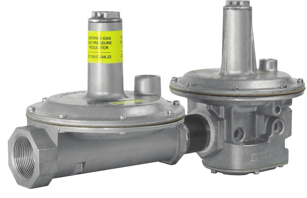
46 325-L SERIES Lever cting Design for 2 psi Piping Systems Maxitrol s 325-L Series line pressure regulators are for 2 psi piping systems. 325 Series regulators are for use on residential, commercial, and industrial applications. The 325 Series features a high leverage linkage assembly to deliver positive dead-end lockup. The regulators are capable of precise regulating control from full flow down to pilot flow L Specifications Pipe Sizes...3/8 to 2 threaded connections with NPT or ISO7-1 threads. Optional...1/8 NPT outlet pressure taps on 325-7, 325-9, and Housing Material L, 325-5L, 325-7L, 325-9L: aluminum. Mounting...Suitable for multi-positional mounting. If ball check vent limiting device is installed, mount in an upright position only. NOTE: ll Maxitrol gas pressure regulators should be installed and operated in accordance with Maxitrol Safety Warning Instructions (see GPR_CS_2PSI_MI_EN.FR). Certifications L, 325-5L, 325-7L, 325-9L, L: NSI Z21.80/CS 6.22 Line Pressure Regulators. Gas Types...Suitable for natural, manufactured, mixed gases, liquefied petroleum gases, and LP gas-air mixtures. Rated Inlet Pressure...2 psi (13.8 kpa) Maxitrol Rated psi (69 kpa) Minimum Inlet Pressure...1 psi (6.9 kpa) Emergency Exposure Limits psi (450 kpa) (inlet side only) Maximum Individual Load...Largest single appliance served by the regulator: 325-3L: 140,000 Btu/h; 325-5L: 425,000 Btu/h; 325-7L: 1,250,000 Btu/h; 325-9L: 2,250,000 Btu/h; : 4,450,000 Btu/h Capacity...Total load of multiple appliance combined 325-3L (3/8, 1/2 ): 250,000 Btu/h; 325-5L (1/2 ): 500,000 Btu/h; 325-5L (3/4, 1 ): 600,000 Btu/h; 325-7L (1 1/4, 1 1/2 ): 1,250,000 Btu/h; 325-9L (1 1/2, 2 ): 2,250,000 Btu/h; : 4,450,000 Btu/h mbient Temperature Ranges to 205 F (-40 to 96 C) NOTE: Capacities are used to determine the maximum multiple appliance load. The largest single appliance served by the regulator should not exceed the maximum individual load specified above. Minimum Regulation...Suitable for pilot flow applications. (Circle P) (0.15 CFH NG). Imblue Technology L, 325-5L, 325-7L, 325-9L models may be ordered with Imblue Technology. Imblue Technology increases corrosion resistance and provides extra protection against the elements for regulators used in outdoor applications. dd suffix letter B to model number when ordering , Maxitrol Company. ll Rights Reserved.
47 LINE REGULTORS Capacities Capacities expressed in CFH (m sp gr gas Model 325-3L Pipe Size 3/8 x 3/8 1/2 x 1/ L 1/2 x 1/ L 325-7L 325-9L L 3/4 x 3/4 1 x 1 1 1/4 x 1 1/4 1 1/2 x 1 1/2 1 1/2 x 1 1/2 2 x 2 1 1/2 x 1 1/2 2 x 2 Outlet Pressure Set Point 7.0 w.c. (1.7 kpa) 10.0 w.c. (2.5 kpa) 7.0 w.c. (1.7 kpa) 10.0 w.c. (2.5 kpa) 7.0 w.c. (1.7 kpa) 10.0 w.c. (2.5 kpa) 7.0 w.c. (1.7 kpa) 10.0 w.c. (2.5 kpa) 7.0 w.c. (1.7 kpa) 10.0 w.c. (2.5 kpa) 7.0 w.c. (1.7 kpa) 10.0 w.c. (2.5 kpa).5 psi (3.4 kpa) 145 (4.1) 110 (3.1) 360 (10.2) 275 (7.8) 370 (10.5) 275 (7.8) 750 (21.2) 525 (14.9) 1390 (39.4) 1050 (29.7) 1800 (51.0) 1450 (41.1) NOTE: See pages for Regulator Sizing Requirements and Examples. Pressure Drop: expressed in CFH (m sp gr gas.75 psi (5.2 kpa) 200 (5.7) 180 (5.1) 485 (13.7) 475 (13.5) 520 (14.7) 450 (12.7) 1000 (28.3) 900 (25.5) 2080 (58.9) 1660 (47.0) 2770 (78.4) 2400 (68.0) Operating Inlet Pressure 1 psi (6.9 kpa) 250 (7.1) 230 (6.5) 500 (14.2) 500 (14.2) 600 (17.0) 570 (16.1) 1250 (35.4) 1125 (31.9) 2250 (63.7) 2090 (59.2) 3460 (98.0) 3190 (90.3) 1.5 psi (10.3 kpa) 250 (7.1) 250 (7.1) 500 (14.2) 500 (14.2) 600 (17.0) 600 (17.0) 1250 (35.4) 1250 (35.4) 2250 (63.7) 2250 (63.7) 4500 (127.4) 4500 (127.4) C US 2 psi (13.8 kpa) 250 (7.1) 250 (7.1) 500 (14.2) 500 (14.2) 600 (17.0) 600 (17.0) 1250 (35.4) 1250 (35.4) 2250 (63.7) 2250 (63.7) 4500 (127.4) 4500 (127.4) Model Number 7.0 w.c. (1.7 kpa).5 psi (3.4 kpa).75 psi (5 kpa) 325-3L 145 (4.0) 204 (5.8) 250 (7.0) 325-5L 400 (11.3) 550 (15.6) 670 (19.0) 325-7L 815 (23.1) 1149 (32.5) 1405 (39.8) 325-9L 1360 (38.5) 2113 (59.8) 2557 (72.4) L 3000 (85.0) 4220 (119.5) 5170 (146.4) Spring Selection Outlet Pressure Range (all models) Certified Spring... 7 to 11 w.c. (1.7 to 2.7 kpa) NOTE: See to pages for complete Spring Selection Chart. 2017, Maxitrol Company. ll Rights Reserved. 47
48 325-L SERIES Lever cting Design for 2 psi Piping Systems Dimensions Model Pipe Size Vent Connection 325-3L 3/8, 1/2 1/8 NPT 325-5L 1/2, 3/4, 1 3/8 NPT 325-7L 1 1/4, 1 1/2 1/2 NPT 325-9L 1 1/2, 2 1/2 NPT L 2, 2 1/2 3/4 NPT Swing Radius 3 (76 mm) 4.9 (124 mm) 6.1 (156 mm) 7.8 (198 mm) 11.0 (279 mm) Dimensions B C 3.5 (89 mm) 5.3 (133 mm) 7.3 (184 mm) 9.4 (239 mm) 13.1 (333 mm) 4.2 (108 mm) 5.9 (149 mm) 8 (203 mm) 10.8 (274 mm) 16.1 (409 mm) NOTE: Dimensions are maximums and to be used only as an aid in designing clearance for the valve. ctual production dimensions may vary somewhat from those shown. 3.9 (98 mm) 5.4 (138 mm) 7 (178 mm) 9.1 (231 mm) 13.5 (343 mm) 325-3L 325-5L , Maxitrol Company. ll Rights Reserved.
49 LINE REGULTORS 325-7L 325-9L Lever cting Design 1 Seal Cap Stack 3 Top Housing 4 Rubber Valve 5 Valve Seat Seal Cap Gasket 7 djusting Screw 8 Spring 9 Vent Connection 10 Diaphragm 11 Diaphragm Plates 12 Bottom Housing NOTE: Diagrams are graphical representations only and may differ from actual product. 2017, Maxitrol Company. ll Rights Reserved. 49

50 325-L SERIES Lever cting Design with OPDs for 5 psi Piping Systems Maxitrol s 325-L Series line pressure regulators with OPDs are for use on piping systems up to 5 psi. The regulator reduces pounds pressure to a level within the appliance or equipment s operating supply range. The line regulator is located upstream of equipment already fitted with an appliance regulator L47 Specifications Pipe Sizes... 3/8 thru 2 threaded connections with NPT or ISO7-1 threads. Housing Material... ll models: aluminum. Mounting ll models with the exception of 325-7L210D and 325-9L210E are suitable for multi-positional mounting L210D and 325-9L210E are to be mounted in a horizontal upright position only. If ball check vent limiting device is installed, mount in an upright position only.... NOTE: Line pressure regulators with separate overpressure protection devices are factory preassembled and supplied to the field as a unit. ll Maxitrol gas pressure regulators should be installed and operated in accordance with Maxitrol Safety Warning Instructions (see LPROPD_MI_EN.FR). Certifications... ll models: NSI Z21.80/CS 6.22 Line Pressure Regulators Gas Types... Suitable for natural, manufactured, mixed gases, liquefied petroleum gases, and LP gas-air mixtures. Rated Inlet Pressure... 5 psi (34.5 kpa) Maxitrol Tested psi (69 kpa) Minimum Inlet Pressure... 1 psi (7 kpa) With 1209, 1239, or 1249 Vent Limiter Installed Natural: 5 psi (34.5 kpa); LP: 2 psi (13.8 kpa) Emergency Exposure Limits psi (450 kpa) (inlet side only) Maximum Individual Load/ Capacity L47 (3/8, 1/2 ) (w/opd 47 attached) ,000 Btu/h 325-3L48 (1/2 ) (w/opd 48 attached) ,000 Btu/h 325-5L48 (1/2 ) (w/opd 48 attached)...235,000 Btu/h 325-5L48 (3/4 ) (w/opd 48 attached)...320,000 Btu/h 325-5L600 (3/4 ) (w/opd 600 attached)...425,000 Btu/h 325-5L600 (1 ) (w/opd 600 attached)...465,000 Btu/h 325-7L210D (1 1/4, 1 1/2 ) (w/opd 210D attached)...1,250,000 Btu/h 325-9L210E (1 1/2, 2 ) (w/opd210e attached)...2,250,000 Btu/h mbient Temperature Ranges to 205 F (-40 to 96 C) Minimum Regulation... Suitable for pilot flow applications. 50 (Circle P) (0.15 CFH NG). 2017, Maxitrol Company. ll Rights Reserved.
51 LINE REGULTORS C US Capacities Capacities expressed in CFH (m sp gr gas Model Number Pipe Size Outlet Pressure Set Point Operating Inlet Pressure 1/2 psi (3.4 kpa) 3/4 psi (5.2 kpa) 1 psi (6.9 kpa) 5 psi (34.5 kpa) 325-3L47 3/8 x 3/ L47 1/2 x 1/ L48 1/2 x 1/ L48 1/2 x 1/ L48 3/4 x 3/ L600 3/4 x 3/ L600 1 x L210D 1 1/4 x 1 1/ L210D 1 1/2 x 1 1/ L210E 1 1/2 x 1 1/2 7 w.c. 125 (3.5) 125 (3.5) 125 (3.5) 125 (3.5) 10 w.c. 100 (2.8) 125 (3.5) 125 (3.5) 125 (3.5) 7 w.c. 125 (3.5) 125 (3.5) 125 (3.5) 125 (3.5) 10 w.c. 105 (2.9) 125 (3.5) 125 (3.5) 125 (3.5) 7 w.c. 160 (4.5) 200 (5.6) 200 (5.6) 200 (5.6) 10 w.c. 120 (3.4) 200 (5.6) 200 (5.6) 200 (5.6) 7 w.c. 235 (6.6) 235 (6.6) 235 (6.6) 235 (6.6) 10 w.c. 235 (6.6) 235 (6.6) 235 (6.6) 235 (6.6) 7 w.c. 320 (9.0) 320 (9.0) 320 (9.0) 320 (9.0) 10 w.c. 245 (6.9) 320 (9.0) 320 (9.0) 320 (9.0) 7 w.c. 345 (9.6) 425 (11.9) 425 (11.9) 425 (11.9) 10 w.c. 260 (7.3) 425 (11.9) 425 (11.9) 425 (11.9) 7 w.c. 375 (10.5) 465 (13.0) 465 (13.0) 465 (13.0) 10 w.c. 285 (8.0) 465 (13.0) 465 (13.0) 465 (13.0) 7 w.c. 815 (22.8) 1120 (31.4) 1250 (35.4) 1250 (35.4) 10 w.c. 580 (16.2) 900 (25.2) 1100 (30.8) 1250 (35.4) 7 w.c. 815 (22.8) 1120 (31.4) 1250 (35.4) 1250 (35.4) 10 w.c. 580 (16.2) 900 (25.2) 1100 (30.8) 1250 (35.4) 7 w.c (38.6) 2000 (56.0) 2250 (63.0) 2250 (63.0) 10 w.c. 890 (24.9) 1750 (49.0) 2100 (58.8) 2250 (63.0) 7 w.c (38.6) 2000 (56.0) 2250 (63.0) 2250 (63.0) 325-9L210E 2 x 2 10 w.c. 890 (24.9) 1750 (49.0) 2100 (58.8) 2250 (63.0) NOTE: See pages for Regulator Sizing Requirements and Examples. Imblue Technology : ll models may be ordered with Imblue Technology. Imblue Technology increases corrosion resistance and provides extra protection against the elements for regulators used in outdoor applications. dd suffix letter B to model number when ordering. 2017, Maxitrol Company. ll Rights Reserved. 51
52 325-L SERIES Lever cting Design with OPDs for 5 psi Piping Systems Pressure Drop Pressure Drop expressed in CFH (m sp gr gas Model Number Pipe Size Pressure Drop 7 w.c. (1.7 kpa) 1/2 psi (3.4 kpa) 3/4 psi (5.2 kpa) 325-3L47 3/8 x 3/8 130 (3.6) 185 (5.2) 225 (6.3) 325-3L47 1/2 x 1/2 135 (3.8) 195 (5.4) 235 (6.6) 325-3L48 1/2 x 1/2 160 (4.5) 225 (6.3) 275 (7.7) 325-5L48 1/2 x 1/2 315 (8.8) 450 (12.6) 545 (15.4) 325-5L48 3/4 x 3/4 325 (9.1) 465 (13.0) 565 (16.0) 325-5L600 3/4 x 3/4 345 (9.6) 490 (13.7) 595 (16.8) 325-5L600 1 x (10.5) 535 (15.0) 650 (18.4) 325-7L210D 1 1/4 x 1 1/4 800 (22.7) 1095 (31.0) 1385 (39.2) 325-7L210D 1 1/2 x 1 1/2 800 (22.7) 1095 (31.0) 1385 (39.2) 325-9L210E 1 1/2 x 1 1/ (38.5) 2113 (59.8) 2557 (72.4) 325-9L210E 2 x (38.5) 2113 (59.8) 2557 (72.4) NOTE: See pages for Regulator Sizing Requirements and Examples. Spring Range Selection Outlet Pressure Range (all models) Certified Spring... 7 to 11 w.c. (1.7 to 2.7 kpa) NOTE: Please refer to pages for complete Spring Selection Chart , Maxitrol Company. ll Rights Reserved.
53 LINE REGULTORS Lever cting Design With OPD NOTE: Diagrams are graphical representations only and may differ from actual product. 1 Seal Cap 8 Spring 15 Spring 22 Diaphragm Plate 2 Stack 9 Vent Connection 16 Top Housing 23 Rubber Seat 3 Top Housing 10 Diaphragm 17 Diaphragm 24 Stem & Valve 4 Rubber Valve 11 Diaphragm Plates 18 Dust Cap 25 Bottom Housing 5 Valve Seat 12 Bottom Housing 19 djusting Screw 6 Seal Cap Gasket 13 Seal Cap 20 Stack 7 djusting Screw 14 Seal Cap Gasket 21 Vent 2017, Maxitrol Company. ll Rights Reserved. 53
 8 (203 mm) 3.")
54 325-L SERIES Lever cting Design with OPDs for 5 psi Piping Systems Dimensions Model Pipe Size Vent Connection Swing Radius Dimensions B C 325-3L47 3/8, 1/ L: 1/8 OPD47: Integral 3 (76 mm) 3.5 (89 mm) 8 (203 mm) 3.9 (99 mm) 325-3L48 1/ L48 1/2, 3/ L600 3/4, L210D 1 1/4, 1 1/ L210E 1 1/2, L: 1/8 OPD48: 1/ L: 3/8 OPD48: 1/ L: 3/8 OPD600: 1/ L: 1/2 OPD210D: 3/ L: 1/2 OPD210E: 1/2 3 (76 mm) 4.4 (112 mm) 4.4 (112 mm) 6.75 (171 mm) 8.3 (211 mm) 3.5 (89 mm) 5.3 (135 mm) 5.5 (140 mm) 7 (178 mm) 9.4 (239 mm) 8.5 (216 mm) 10 (254 mm) 11 (279 mm) 15.4 (391 mm) 20.6 (523 mm) NOTE: Dimensions are maximums and to be used only as an aid in designing clearance for the valve. ctual production dimensions may vary somewhat from those shown. 3.9 (99 mm) 5.4 (137 mm) 5.4 (137 mm) 9 (229 mm) 9.1 (231 mm) B 325-3L L L , Maxitrol Company. ll Rights Reserved.


55 LINE REGULTORS 325-5L L210D 325-9L210E 2017, Maxitrol Company. ll Rights Reserved. 55
56 SPRING SELECTION CHRT Model # Part Number djustable Models: Color Code Outlet Pressure (In. w.c.) pprox Inner Diameter pprox Length Model # Part Number djustable Models: Color Code Outlet Pressure (In. w.c.) pprox Inner Diameter pprox Length RV12L RV20L RV20LT RV47D RV47L RV47D RV47L RV48 RV48T R400 R400S RV52 R500 R500S R500 R500S RV53 R600 R600S R1210T-13 R1210T-35* R1210T-48 R1210T-610 R1210T-812 R R * R R R R R2010T-35* R2010T-48 R2010T-610 R2010T-812 R R R R R R * R R R R R R * R R R R4810T-36* R4810T-48 R4810T-512 R4810T-610 R400B10-13 R400B10-25 R400B10-36* R400B10-38 R400B R400B R400B R R R * R R R R Brown Orange Brown Orange Orange Black Green Brown Orange Violet Brown Orange S Steel Orange Brown Pink Violet Brown Pink Orange Violet 1.0 to to to to to to to to to to to to to to to to to to to to to to to to to to to to to to to to to to to to to to to to to to to to to to to to R to R R R * R R R R Brown Pink Orange Violet 1.0 to to to to to to to R600 R600S RV61 RV81 210D 210D RV91 210E 210E RV G 210G RV J 220D, E,G,& J R R R R R * R R R R R R R * R R R R R R R R R R R * R R R R R R R R R R R * R R R R R R R R R R * R R R R R R R325C R325C Yellow Brown Pink Orange Brown Pink Orange Violet Green Yellow Black Brown Pink Orange Violet Green Yellow Black Brown Pink Orange Violet Green Yellow Black Pink Violet Yellow Black Tagged Tagged 10 to to to to to to to to to to to to to to to to to to to to to to to to to to to to to to to to to to to to to to to to to to to to to to to to to to 42 1 psi-3 psi 2 psi-5 psi * Standard Spring , Maxitrol Company. ll Rights Reserved.
57 SPRING SELECTION CHRT Model # Part Number djustable Models: Color Code Outlet Pressure (In. w.c.) pprox Inner Diameter pprox Length Model # Part Number Zero Governor Models: How Used Color Code pprox Inner Diameter pprox Length R325C10-26 R325C10-59 R325C10-412* R325C R325C R325C R325C10-P12 R325E10-26 R325E10-59 R325E10-412* R325E R325E R325E R325E10-P12 R R * R R R R325G Violet White Yellow Tagged Violet White Yellow Tagged Violet Yellow Black White 2.0 to to 9.0 # 4.0 to to to to 30 1 psi-2 psi 2.0 to to 9.0 # 4.0 to to to to 30 1 psi-2 psi 2.0 to to to to to to R400Z R500Z R600Z 210DZ 210EZ 210GZ 210JZ R400B10-13 R400B10Z R R500B10Z R R600B10Z R R210D10Z R R210E10Z R R210G10Z R R210J10Z Regulate Counter Regulate Counter Regulate Counter Regulate Counter Regulate Counter Regulate Counter Regulate Counter Brown Brown Brown Brown Brown Brown Brown R R * R R R R325J Violet Yellow Black White 2.0 to to to to to to Model # Part Number djustable Models: Min / Max Color Code Outlet Pressure (In. w.c.) pprox Inner pprox Diameter Length * Standard Spring **L.P. - May be used with any minimum spring. # - or 6.0 to 10.0 for 5 psi SR400B10H MR410B10L Max Min S Steel 3.0 to to NOTE: Spring free length is given as an aid for the purpose SR400 SR400B10H-1 MR410B10L SR400B10H MR410B10L-1 Max Min Max Min White S Steel 2.5 to to to to of identification only. Variations of ± 1 2, although unlikely, can occur. This variation will not affect the spring range. SR400B10H-1 MR410B10L-1 Max Min White 3.0 to to SR400B10L-4 Min Black 2.5 to SR400-2** MR410B102-2 Max 7.5 to SR500B10H MR510B10L Max Min S Steel 3.0 to to SR500 SR500B10H-1 MR510B10L SR500B10H MR510B10L-1 Max Min Max Min White S Steel 1.5 to to to to SR500B10H-1 MR510B10L-1 Max Min White 2.0 to to SR500-2** SR500B10H\L-2* Max Black 7.5 to SR600B10H MR610B10L Max Min S Steel 3.0 to to SR600 SR600B10H-1 MR610B10L SR600B10H MR610B10L-1 Max Min Max Min White S Steel 2.5 to to to to SR600B10H-1 Max White 3.0 to MR610B10L-1 Min 1.0 to , Maxitrol Company. ll Rights Reserved. 57
58 SIZING REGULTOR See for our Regulator Sizing Program. Please contact Maxitrol directly for more information on sizing a regulator. System Requirements When sizing a regulator the following must be known: Gas Type vailable Inlet Pressure Desired Outlet Pressure Zero Governor pplication (indicated by model number ending in Z ) Will the regulator control main burner and pilot load OR main burner only? Required minimum and maximum flow rate in cfh or m 3 /h or Btu/h Pipe Size In most cases, the manifold pipe size has already been selected on the basis of good engineering practice, and the regulator pipe size should conform to this size. The capacity of any regulator is not an absolute value but will vary with the application depending on the prevailing differential pressure. Service and installation must be performed by a trained/experienced service technician. ll products used with combustible gas must be installed and used strictly in accordance with the instructions of the Original Equipment Manufacturer (OEM) and with all applicable government codes and regulations, e.g. plumbing, mechanical, and electrical codes and practices. These instructions do NOT supersede OEM s installation or operating instructions. ll Maxitrol products should be installed and operated in accordance with Maxitrol Safety Warning Instructions. HOW TO CLCULTE PRESSURE DROP T VRIOUS FLOW RTES FROM CPCITY CHRT LP pplications - When using natural gas pressure drop chart to determine LP pressure drop in terms of Btu/h, multiply NT Btu/h by 1.61; in terms of CFH multiply NT CFH by Formula: P2 = P1 x (Q2/Q1) 2 P2 = Pressure drop at desired flow rate P1 = Known pressure drop Q2 = Desired flow rate Q1 = Known flow rate. Check Capacity Chart, insuring regulator has ample range B. Know the minimum encountered inlet pressure. of regulation and individual load capacities (for use with pilot) MINIMUM INLET PRESSURE MINUS P2 MUST for the application. BE GRETER THN DESIRED OUTLET PRESSURE. Solve for P2 using the formula above. (See examples on page 59.) , Maxitrol Company. ll Rights Reserved.
59 SIZING REGULTOR Sizing Examples RUBBER SET POPPETS For main burner and pilot load applications. Example: To select an RV type regulator: Known: Single 150,000 Btu/h main burner; pipe size 1/2 ; inlet pressure 7 w.c.; outlet pressure 4 w.c. Solution: The RV48 (1/2 ) has a maximum capacity of 230,000 Bth/h and a maximum individual load of 160,000 Btu/h. The pressure drop at a flow rate of 150,000 Btu/h is 0.4 w.c., well below the available differential of 3 w.c. The RV48 (without L fixed orifice) is the correct regulator to use for the application. STRIGHT-THRU-FLOW (S-T-F) For main burner only applications not requiring a lockup type regulator. When sizing the S-T-F Series, it is recommended that pressure drop not exceed 1/2 of available differential pressure. Example: To select an RV type regulator: Known: Flow rate 2,000,000 Btu/h; pipe size 1 1/4 ; inlet pressure 9 w.c.; outlet pressure 5 w.c. Solution: The RV81(1 1/4 ) has a maximum capacity of 2,500,000 Btu/h. The pressure drop at a flow of 2,000,000 Btu/h is 0.66 w.c. The RV81 (1 1/4 ) is the correct regulator to use with this application. The pressure drop of the RV61 (1 1/4 ) at a flow rate of 2,000,000 Btu/h is 2.64 w.c. This is within the available differential but exceeds the recommended 50% maximum. LEVER CTING For main burner and pilot load application requiring positive dead-end lockup (see Definitions page 63). Example: To select a 325 Series regulator: Known: Single 145,000 Btu/h burner; pipe size 1/2 ; inlet pressure 2 psi; outlet pressure 7 w.c. Solution: The s pressure drop at a flow rate of 145,000 Btu/h is 7 w.c., well below the available differential of 1 3/4 psi. The (1/2 ) is the correct regulator to use with this application. BLNCED VLVE For main burner and pilot load application requiring a lockup type regulator or zero governor usage (see Definitions page 63). Example: To select a 210 or R/RS Series regulator: Known: Desired flow rate 6,000,000 Btu/h; pipe size 1 1/2 ; inlet pressure 1 psi; outlet pressure 9 w.c. Solution: The 210E (1 1/2 ) has a maximum capacity of 10,000,000 Btu/h. The 210D (1 1/2 ) has a capacity of 6,000,000 Btu/h. Therefore, the 210E (1 1/2 ) will give you the desired outlet pressure of 9 w.c. and is the correct regulator to use for the application. 2017, Maxitrol Company. ll Rights Reserved. 59


 and 5 psi (natural) inlet pressure with 325-3 and 325-3L regulators; OPD48, OPD600. Color - green. 1/8 NPT.")
 and 5 psi (natural) inlet pressure with 325-5 and 325-5L regulators; OPD210D. Color - brass. 3/8 NPT.")

60 CCESSORIES Vent Tube Connector Threaded sleeve - two piece assembly where the nut is tightened inside male connector. 1103: connects 1/8 female pipe thread to 1/8 O.D. tubing. 1104: connects 1/8 female pipe thread to 1/4 O.D. tubing. Threaded sleeve nut - for RV20V. 1108: 5/16-24 threaded sleeve nut for 1/8 O.D. tubing. Compression fitting - where nut and sleeve are slipped over tubing and tightened into fitting body : connects 1/4 female pipe thread to 1/4 O.D. tubing : connects 1/8 female pipe thread to 1/8 O.D. tubing : connects 3/8 female pipe thread to 3/8 O.D. tubing : connects 1/2 female pipe thread to 3/8 O.D. tubing Vent Limiting Device: Optional automatic vent limiting device - ball check permits unobstructed inhalation for fast regulator diaphragm response on opening cycle, but limits gas escapement to within NSI standards should a diaphragm rupture. NOTE: When using the vent limiting device, regulator must be mounted in a horizontal upright position. 1204: CS certified for up to 1/2 psi (14 w.c.) inlet pressure. Use on RV48, RV52, RV53, RV61, R400(S), R500(S), R600(S) regulators. Color - brass. 1/8 NPT. 1209: CS certified for 2 psi (LP) and 5 psi (natural) inlet pressure with and 325-3L regulators; OPD48, OPD600. Color - green. 1/8 NPT. 1234: CS certified for up to 1/2 psi (14 w.c.) inlet pressure with RV81. Color - brass. 3/8 NPT. 1239: CS certified for 2 psi (LP) and 5 psi (natural) inlet pressure with and 325-5L regulators; OPD210D. Color - brass. 3/8 NPT. 1249: CS certified for 2 psi (LP) and 5 psi (natural) inlet pressure with 325-7, 325-7L, 325-9, and 325-9L regulators; OPD210E. Color - brass. 1/2 NPT Satisfies NSI Standards for both Natural and LP gas. NOTE: Vent limiters are not recommended for use in models RV91, RV111, RV131, and 210 Series. Vent Limiting Orifice 1206: Orifice hole is on side of body, under head. Fixed orifice equally limits inhalation and escapement. Use on RV48, RV52, RV53, RV61, R400(S), R500(S), R600(S) regulators. Color- brown. 1/8 NPT Satisfies NSI Standards for both Natural and LP gas , Maxitrol Company. ll Rights Reserved.

(Z), and R600(S)(Z). 1315-5: for 3/8 NPT vent.")


61 CCESSORIES C US Vent Protector: Designed for outdoor applications. Use on vent opening to protect breather hole from rain, snow, dust, insects and other foreign particles. NOTE: Vent protector MUST be mounted in an upright position. 1315: for 1/8 NPT vent. For outdoor use in 325-3, 325-3L, RV48, RV52, RV53, RV61, R500(S)(Z), and R600(S)(Z) : for 3/8 NPT vent. For outdoor use in 325-5, 325-5L, RV81, 210D. 1325: for 1/2 NPT vent. For outdoor use in 325-7, 325-7L, 325-9, 325-9L, RV91, 210E NOTE: NOT a vent limiting device. Consult Maxitrol regarding other configurations. Vent Dampener KVOP-3: Used on 325-5, 325-5L. KVOP-4: Used on 325-7, 325-7L, 325-9L KVOP-3 NOTE: Should not be used with vent limiter. Vent Screen Brass, 40 mesh screen flame arrestor for insertion in vent outlet. Prevents ignition of gas-air mixture which might be present in upper diaphragm chamber : for 1/8 NPT vent : for 1/4 NPT vent : for 3/8 NPT vent : for 1/2 NPT vent : for 3/4 NPT vent. Pressure Tap Connector PF10: Pressure tap connector installed as part of the control. It is a hose fitting incorporating a captured sealing means for testing inlet and outlet pressures. This eliminates the need for a special barb fitting. Dust Cap Use on vent opening to prevent blockage of breather hole from dust or other foreign particles. Standard on all L models with 1/8 threaded vent. 1309: for 1/8 NPT vent. Press-in plastic cap PF Tamper Proof Seals Permanent pressure sensitive backed paper. ttempted removal of these seals will destroy the face stock, leaving adhesive residue on surface beneath. Therefore, tampering can be easily detected. vailable for all threaded models. Outlet pressure printed on seal : for RV12, RV20L, RV47, RV48, RV52, RV53, RV61, R400(S)(Z), RV500(S)(Z), R600(S)(Z), 325-3, and : for RV81, RV91, RV111, 210D, 210E, 210G, 325-7, , Maxitrol Company. ll Rights Reserved. 61
62 CHOOSING VENT CCESSORY NOTE: If vent limiting device is not used, regulator vent must be piped in accordance with government and local codes and regulations. RV12L, RV20L RV20VL RV47 RV48 RV48L RV52, RV53, RV61 RV81 RV91 (2 1/2 pipe size) RV91 (2 pipe size) RV111, RV D 210E Integral vent limiting orifice with dust cap standard. Integral vent limiting orifice with dust cap standard or use 1108 threaded sleeve nut and run vent line as per code. Must order: L suffix - Integral vent limiting orifice, includes dust cap; or D suffix - integral ball-check limiting device, includes dust cap. 1/8 NPT vent tap. Optional 1204 or 1206 vent limiter. Optional 1309 dust cap. Optional or plastic thread protector. Integral vent limiting orifice. 1/8 NPT vent tap. Optional 1204 or 1206 vent limiter or 1315 vent protector. 3/8 NPT vent tap. Optional 1234 vent limiter or vent protector. 1/4 NPT vent tap. Optional 1315 vent protector. Vent limiter not approved for this model. 1/2 NPT vent tap. 2 pipe size. Optional 1325 vent protector. Vent limiter not approved for this model. 3/4 NPT vent tap. Vent limiter not approved for these models. 3/8 NPT vent tap. Optional vent protector. Vent limiter not approved for this model. 1/2 NPT vent tap. Optional 1325 vent protector. Vent limiter not approved for this model. 210G, 210J 3/4 NPT vent tap. Vent limiter not approved for these models. 220D, 220E, 220G, 220J Pilot regulator is equipped with 1206 vent limiting orifice, separate vent line is not required , 325-3L 1/8 NPT vent tap. Optional 1209 vent limiting device or 1315 vent protector , 325-5L 3/8 NPT vent tap. Optional 1239 vent limiting device or vent protector , 325-7L 1/2 NPT vent tap. Optional 1249 vent limiting device or 1325 vent protector , 325-9L 1/2 NPT vent tap. Optional 1249 vent limiting device or 1325 vent protector. R400(S), R500(S), R600(S) OPD47 OPD48, OPD600 OPD210D OPD210E 1/8 NPT vent tap. Optional 1204 vent limiting device. Integral vent limiting orifice, includes dust cap. 1/8 NPT vent tap. Optional 1209 vent limiting device or 1315 vent protector. 3/8 NPT vent tap. Optional 1239 vent limiting device or vent protector. 1/2 NPT vent tap. Optional 1249 vent limiting device or 1325 vent protector. NOTICE Maxitrol vent limiting devices eliminate the need to run vent piping to the outside. Vent limiting devices are designed for use indoors and in spaces where limiting the amount of gas escapement due to diaphragm failure is critical. Vent limiting devices should not be used outdoors if they are exposed to the environment. Vent protectors are available for all outdoor applications to ensure proper vent protection , Maxitrol Company. ll Rights Reserved.
63 DEFINITIONS Dead End Lockup Pressure will be maintained within NSI/CS limits under no flow conditions. The amount of climb above set point is influenced by inlet pressure, flow rate before no flow condition and piping arrangement. Dead end lockup pressure regulators must be properly sized for desired performance. Differential Pressure The difference between inlet pressure to the pressure regulator and outlet pressure from the pressure regulator. To obtain differential pressure, subtract the desired outlet pressure from available inlet pressure. Line Pressure Regulator pressure regulator intended for installation in a building gas distribution system between the building service regulator or LP-gas 2 psi service regulator and gas utilization equipment. Lockup Type Under no flow conditions, outlet pressure will rise above adjusted pressure but will not rise to line pressure. Minimum Capacity (Main Burner Only) Minimum capacity of a pressure regulator designed to control the flow to the main burner only. Maximum Capacity (Main Burner Only) Maximum capacity of a pressure regulator at which the pressure regulator will control main burner pressure within acceptable limits. Maximum Capacity (Main Burner and Pilot) Maximum capacity of a pressure regulator at which the pressure regulator will control main burner and pilot line pressure within acceptable limits. Capacity Total load Btu/h of all appliances combined. Maximum Individual Load Largest single appliance or burner served by the pressure regulator. Non-Lockup Type Under static conditions when no gas is flowing, outlet pressure will rise to line pressure. Overpressure Protection Device (OPD) device which under abnormal conditions will act to reduce, restrict, or shut off the supply of gas flowing into a system to prevent pressure in that system from exceeding 2 psi. Monitoring Regulator: n overpressure protection device which functions as a second pressure regulator in series with the primary pressure regulator. Overpressure Relief Device: n overpressure protection device which functions by discharging gas from the downstream system to a safe location. Overpressure Shut-Off Device: n overpressure protection device which functions by completely shutting off the flow of gas into the downstream system. Pressure Drop The natural loss of pressure that occurs in the pressure regulator (or in any valve or pipe) due to friction. This friction impedes fluid motion, without regard to artificial losses deliberately created by diaphragm action. The equivalent flow rate for a loss in given pressure with the pressure regulator valve in a normally wide open position. Rated Inlet Pressure The highest inlet pressure for which the control is intended to be used. Vent Limiter means that limits the flow of gas from the atmospheric chamber to the atmosphere in the event of a diaphragm rupture. This may be either a limiting orifice or a ball check vent limiting device. Limiting Orifice Type: vent limiter where the flow through the limiter is the same in both directions Zero Governors They require an external impulse signal, such as top loading with pressure or generating vacuum in the downstream piping. Maximum Individual Load Capacity 1. The maximum capacity or flow at which a line pressure regulator will control lockup pressure within acceptable limits. 2. The maximum capacity or flow at which a pressure regulator will control pilot line pressure within acceptable limits. 2017, Maxitrol Company. ll Rights Reserved. 63
64 GF SERIES Gas and ir Filters Gas and air filters protect downstream controls (regulators, automatic shut-off valves) from particulate contamination. Recommended for use upstream of fittings, regulators, and controls. pplications for the residential, commercial cooking, process heating, and industrial burner industries. The unique filter mat material will not allow particle infiltration over 0.05mm (50 microns). GF60 Specifications Pipe Sizes... 1/2 to 2 threaded connections with NPT or ISO7-1 threads. Housing Material... GF40, GF60, GF80: aluminum. Mounting... Suitable for multi-positional mounting, preferably with lid facing down or to the side to facilitate removal of debris during maintenance. NOTE: ll Maxitrol gas filters should be installed and operated in accordance with Maxitrol Safety Warning Instructions (see GF_IO_EN.DE). Certifications... ccording to DIN 3386, Gas ppliances 2009/142/EC and Pressure Equipment Directive 97/23/EEC. Gas Types... Suitable for natural, manufactured, mixed gases, liquefied petroleum gases, LP gas-air mixtures, sewer gas, and air. Pressure Tap Connector... Optional: Pressure tap (PF10) connections inlet and/or outlet side. Maximum Inlet Pressure psi (400 kpa) mbient Temperature Ranges to 175 F (-20 to 80 C) Storage and Transport Temp to 175 F (-50 to 80 C) Filter Replacement... GF40 Models: KIT-GF40... GF60 Models: KIT-GF60... GF80 Models: KIT-GF , Maxitrol Company. ll Rights Reserved.


 4.3 (109 mm) 3.7 (94 mm) GF80 4 (102 mm) 6.2 (158 mm) 6.")
65 GS ND IR FILTERS U.TR Dimensions NPT Model ISO 7-1 Model Pipe Size Pressure GF40-44 GF40M-44 1/2 100 kpa, 400 kpa GF60-66 GF60M-66 3/4 100 kpa, 400 kpa GF60-88 GF60M kpa, 400 kpa GF GF80M /4 100 kpa, 400 kpa GF GF80M /2 100 kpa, 400 kpa GF GF80M kpa, 400 kpa Outer Dimensions Model Swing Radius B C GF (41 mm) 2.1 (53 mm) 2.7 (69 mm) 2.3 (58 mm) GF (66 mm) 3.7 (94 mm) 4.3 (109 mm) 3.7 (94 mm) GF80 4 (102 mm) 6.2 (158 mm) 6.2 (163 mm) 6.4 (163 mm) GF40 GF60 GF , Maxitrol Company. ll Rights Reserved. 65

66 GF1000 SERIES Gas and ir Filters Gas and air filters protect downstream controls (regulators, automatic shut-off valves) from particulate contamination. Recommended for use upstream of fittings, regulators, and controls. pplications for the residential, commercial cooking, process heating, and industrial burner industries. The unique filter mat material will not allow particle infiltration over 0.05mm (50 microns). GF1000MF40 Specifications Pipe Sizes... DN40, DN50, DN65. SME/NSI Class 125, 1 1/2 to 2 1/2 flanged. Contact Maxitrol Company for availability. Housing Material... luminum. Mounting... Suitable for multi-positional mounting, preferably with lid facing down or to the side to facilitate removal of debris during maintenance. NOTE: ll Maxitrol gas filters should be installed and operated in accordance with Maxitrol Safety Warning Instructions (see GF_IO_EN.DE). Certifications... ccording to CE0085Q0979 Gas Types... Suitable for natural, manufactured, mixed gases, liquefied petroleum gases, LP gas-air mixtures, sewer gas, and air. Pressure Tap Connector... Optional: Pressure tap (PF10) connections inlet and/or outlet side. Maximum Inlet Pressure psi (600 kpa) mbient Temperature Ranges to 175 F (-20 to 80 C) Storage and Transport Temp to 175 F (-50 to 80 C) Filter Replacement Kit... KT-GF1000MF , Maxitrol Company. ll Rights Reserved.
Service and installation must be performed by a trained/experienced service technician.
 CATALOG Service and installation must be performed by a trained/experienced service technician. All products used with combustible gas must be installed and used strictly in accordance with the instructions
CATALOG. 2 nd Edition
 CATALOG 2 nd Edition Service and installation must be performed by a trained/experienced service technician. All products used with combustible gas must be installed and used strictly in accordance with
Gas Pressure. Regulators Catalog. For Industrial Engines and Generator Sets. 2011, Maxitrol Company. All Rights Reserved.
 Gas Pressure Regulators Catalog For Industrial Engines and Generator Sets 1 GAS PRESSURE REGULATORS For Industrial Engines and Generator Sets Service and or installation must be performed by a trained,
GAS PRESSURE REGULATORS AND FILTERS.
 GAS PRESSURE REGULATORS AND FILTERS R www.mertikmaxitrol.com WARNING Service and installation must be performed by a trained/experienced service technician. All products used with combustible gas must
210 & 220 series gas pressure regulators for industrial applications
 ULLETIN MS2013-11/00 210 & 220 series gas pressure regulators for industrial applications 210 Series Dimensions and Spring Ranges D E D E DIMENSIONS Model and Illustration Number Pipe Size Diameter Dimensions
Service and installation must be performed by a trained/experienced service technician.
 CATALOG DRAFT 09.18.2013 Service and installation must be performed by a trained/experienced service technician. All products used with combustible gas must be installed and used strictly in accordance
Modulating Valves for Atmospheric, Infrared, and Direct Fired Burners
 BULLETIN MT2035-07/05 Modulating Valves for Atmospheric, Infrared, and Direct Fired Burners M/MR Series M411, M511, M611 M420, M520, M620, MR410, MR510, MR610 MR212D, MR212E, MR212G and MR212J (Flanged),
GM-7000 Series CE Approved Gas Control Valve
 Product Bulletin Issue Date November 16, 2012 GM-7000 Series CE Approved Gas Control Valve The GM-7000 Series multi-function gas control valve works in conjunction with an electronic sequence control unit
M/MR Modulating Valves TABLE OF CONTENTS DESCRIPTION SPECIFICATIONS. For Atmospheric, Infrared, and Direct Fired Burners
 M/MR Modulating Valves design certified For Atmospheric, Infrared, and Direct Fired urners TALE OF CONTENTS Description/Specifications... 1 Introduction... 2 Direct Fired Applications (Negative Pressure)...
Spring Loaded Regulators Constant Loaded Regulators Twin Parallel Flow Regulators Field Service Regulators
 Product Line Brochure J0B Effective Date 2/01 Spring Loaded Regulators Constant Loaded Regulators Twin Parallel Flow Regulators Field Service Regulators P R O D U C T L I N E O V E R V I E W Regulator
Ratio Regulator Zero Governor. FRG/6 Series
 Ratio Regulator Zero Governor FRG/6 Series CSA Certified ANSI Z21.18 / CSA 6.3 CSA Requirement # 5.01 Zero Governor and Gas/Air Regulator File # 157406 US and Canadian Models FRG 705/6 FRG 707/6 FRG 710/6
G196 Series BASOTROL Redundant Combination Gas Valve with Manual Shutoff Valve
 Installation Instructions Issue Date March 13, 2013 G196 Series BASOTROL Redundant Combination Gas Valve with Manual Shutoff Valve Application The G196 valves are suitable for use with natural gas, Liquefied
VG Series VGG and VGD Gas Valves for use with SKP Electro-hydraulic Actuators
 VG Series VGG and VGD Gas Valves for use with SKP Electro-hydraulic Actuators Technical Instructions Document No. 155-51P5 VG August 11, 005 GAS009R1 VGG VGD0 VGD0 Description Only when assembled to SKP
1800CPB2 Service Regulators Maximum Inlet Pressure 125 PSIG
 A C E D SB-8520.2 1800CPB2 Service Regulators Maximum Inlet 125 PSIG AMC Quality System QMI is Accredited by: C R E D I T ISO 9001 Certified Certificate #006697 R E ANSI RAB G I S T R A R Dutch Council
VG Series VGG and VGD Gas Valves for use with SKP Electro-hydraulic Actuators
 VG Series VGG and VGD Gas Valves for use with SKP Electro-hydraulic Actuators Technical Instructions Document No. 155-51P5 VG August 1, 01 VGG VGD0 VGD0 Description Only when assembled to Series SKP actuators
G196 Series BASOTROL Redundant Combination Gas Valve with Manual Shutoff Valve
 Installation Instructions Issue Date August 19, 2008 G196 Series BASOTROL Redundant Combination Gas Valve with Manual Shutoff Valve Application The G196 valves are suitable for use with natural gas, Liquefied
North American Orifice Metering System
 Combustion North American Orifice Metering System 8697 and M8697 Metering Orifices accurately measure gas flows to industrial burners. They are compact, inexpensive, and can be installed in individual
36E DSI, HSI & Proven Pilot Two-Stage Combination Gas Valve INSTALLATION INSTRUCTIONS
 INLET PRESS TAP WTE-RODGERS 36E96-314 DSI, HSI & Proven Pilot Two-Stage Combination Gas Valve INSTALLATION INSTRUCTIONS Operator: Save these instructions for future use! FAILURE TO READ AND FOLLOW ALL
Model 1800 PFM Series Regulator. Technical Bulletin
 Model 0 PFM Series Regulator Technical Bulletin Model 0 PFM Series Regulator 0 Elster American Meter The 0 PFM Series regulators are designed to control natural gas, air, nitrogen, carbon dioxide, propane
Certified LP/Propane Line Pressure Regulator Guidebook
 3rd Edition Certified LP/Propane Line Pressure Regulator Guidebook 2 & 5 PSI Systems 2 3 The specifications in this Handbook refer to Maxitrol line pressure regulators used in LP/Propane applications only.
36C/36D HSI, DSI Proven Pilot Gas Valves INSTALLATION INSTRUCTIONS
 36C/36D HSI, DSI Proven Pilot Gas Valves INSTALLATION INSTRUCTIONS Operator: Save these instructions for future use! FAILURE TO READ AND FOLLOW ALL INSTRUCTIONS CAREFULLY BEFORE INSTALLING OR OPERATING
Gas Appliance Pressure Regulators and. Line Pressure Regulator. FRS 7../6 Series FRS 5... Series
 Gas Appliance Pressure Regulators and Line Pressure Regulators FRS../6 Series FRS 5... Series CSA Certified ANSI Z21.18 CSA 6.3 as a Gas Appliance Pressure Regulator ANSI Z21.80 CSA 6.22 (FRS/6 series
GM Series Dual-Block Multi-Function Gas Control Valves
 Installation Sheets Manual 121 Gas Combustion Combination Controls and Systems Section G Technical Bulletin GM Issue Date 0297 GM Series Dual-Block Multi-Function Gas Control Valves Figure 1: GM Series
SR100 Series Service Regulators. Technical Bulletin
 SR00 Series Service Regulators Technical Bulletin Model SR00 Series Regulator 0 Elster American Meter The compact, high capacity SR service regulator is designed for residential or light commercial/industrial
1800CPB2 Service Regulators
 SB 8520.5 1800CPB2 Service Regulators Maximum Inlet Pressure 125 PSIG Table of Contents 1800CPB2 Regulator Information................ 2-3 1800CPB2 Capacity Performance................ 4-6 1-1/4" Models,
Operator: Save these instructions for future use!
 INLET PRESS TAP WHITE-RODGERS 36E93-304 Delay-Opening Combination Gas Valve INSTALLATION INSTRUCTIONS Operator: Save these instructions for future use! FAILURE TO READ AND FOLLOW ALL INSTRUCTIONS CAREFULLY
Instruction Manual 742 5/1/2009. Eclipse Ratio Regulators ES Series Version 1
 Instruction Manual 742 5/1/2009 Eclipse Ratio Regulators ES Series Version 1 Copyright Copyright 1997 by Eclipse, Inc. All rights reserved worldwide. This publication is protected by federal regulation
LINE PRESSURE REGULATOR GUIDEBOOK 7TH EDITION
 CERTIFIED LINE PRESSURE REGULATOR GUIDEBOOK 7TH EDITION 2 AND 5 PSI SYSTEMS 2 3 This Handbook contains information from national heating and plumbing ordinances or codes that may have been adopted or incorporated
Gas Appliance Pressure Regulators with integrated gas filter. FRI/6 Series
 Gas Appliance Pressure Regulators with integrated gas filter FRI/6 Series CSA Certified ANSI Z21.18 / CSA 6.3 Gas Appliance Pressure Regulator File # 1135455 EU Gas Appliance Directive EN 88 CE-0087 AU
627 Series Pressure Reducing Regulators
 627 Series Pressure Reducing Regulators Introduction The 627 Series direct-operated pressure reducing regulators (Figure 1) are for low and high-pressure systems. These regulators can be used with natural
XDF BURNERS DUAL FUEL EXCESS AIR BURNER FEATURES DESCRIPTION EXCESS AIR OPERATION
 DUAL FUEL EXCESS AIR BURNER MODEL: 3610, 3651 Revision: 0 FEATURES Burns all fuel gases or light oils Nozzle mix design for on ratio control or excess air 350% excess air all sizes on gas or oil Turndown
36E DSI and HSI Two-Stage Combination Gas Valve INSTALLATION INSTRUCTIONS
 INLET PRESS TAP WTE-RODGERS 36E54-214 DSI and HSI Two-Stage Combination Gas Valve INSTALLATION INSTRUCTIONS Operator: Save these instructions for future use! FAILURE TO READ AND FOLLOW ALL INSTRUCTIONS
INSTRUCTIONS FOR CONVERTING CONDENSING GAS MOBILE HOME FURNACES MODEL SERIES: CMA3*, CMC1*, VMA3*, VMC1*
 INSTRUCTIONS FOR CONVERTING CONDENSING GAS MOBILE HOME FURNACES MODEL SERIES: CMA3*, CMC1*, VMA3*, VMC1* THIS KIT CONTAINS: AOPS7741 (NATURAL TO PROPANE CONVERSION PARTS FOR MODEL SIZE, 50) AOPS7742(NATURAL
Gas Appliance Pressure Regulators with integrated gas filter. FRI/6 Series
 Gas Appliance Pressure Regulators with integrated gas filter FRI/6 Series CSA Certified ANSI Z21.18 / CSA 6.3 Gas Appliance Pressure Regulator File # 1135455 EU Gas Appliance Directive EN 88 CE-0087 AU
Line Pressure Regulators Class I or Class II. FRS 7../6 Series
 Line Pressure Regulators Class I or Class II FRS 7../6 Series CSA Certified ANSI Z21.80 / CSA 6.22 as a 5 PSI Class I or Class II Line Pressure Regulator File # 1205910 NPT Threaded Versions FRS 705/6
Design and Application Details MICRO-RATIO Valves
 Flow Control Valves Page 7003 Design and Application Details MICRO-RATIO Valves Principle of Operation MICRO-RATIO Valve assemblies typically consist of a fixed-gradient air butterfly valve mechanically
Model 1800 PFM Series Regulator For Constant Outlet Pressure Precise Fixed Factor Measurement From 0.5 to 30 PSIG
 A C E D SB 8551.3 Model 1800 PFM Series Regulator For Constant Precise Fixed Factor Measurement From 0.5 to 30 G AMC Quality System QMI is Accredited by: C R E D I T ISO 900 Registered R E ANSI RAB G I
G96 Series BASOTROL Dual Operator Valve
 Installation Instructions 9. Issue Date February 22, 2013 G96 Series BASOTROL Dual Operator Valve Applications The G96 valves are combination, dual operator, automatic valves available with or without
Industrial Regulator Series 1800/2000
 E S 85. Industrial Regulator Series / M Quality System QMI is ccredited by: R E I T ISO 9 ertified R E NSI R G I S T R R utch ouncil for ccreditation Measurement Engineers Since 86 merican Meter Series
Noth American 7347 High Pressure Gas Regulators
 Combustion Noth American 7347 High Pressure Gas s Bulletin 7347 7347 s reduce high gas supply pressures to practical use levels. Since capacities will vary with the pressure drop across the regulator (see
Models 461-S, 461-8S and S Regulators. R-1330 Rev. 7
 Models 461-S, 461-8S and 461-12S Regulators R-1330 Rev. 7 461-S, 461-8S and 461-12S Regulators The Sensus Models 461-S, 461-8S and 461-12S are balanced valve, spring type regulators designed for distribution
1800CPB2 Pilot-Loaded Service Regulators
 1800CPB2 Pilot-Loaded Service Regulators Technical Bulletin www.elster-americanmeter.com Table of Contents 1800CPB2 Regulator Information................ 2-3 1800CPB2 Capacity Performance................
e G) GOVERNOR t,5 ii:i! Line Pressure Regulators
 GOVERNOR t,5 ii:i! Line Pressure Regulators") Line Pressure Regulators @ - c - e G) t,5 ii:i! 1rlr1t APPLICATION NOTES 1rlr1t A. The Governor regulator is ANSI Z21.80a and ANSI Z21.18 certified for vent limited installations (indoor installations
Line Pressure Regulators @ - c - e G) t,5 ii:i! 1rlr1t APPLICATION NOTES 1rlr1t A. The Governor regulator is ANSI Z21.80a and ANSI Z21.18 certified for vent limited installations (indoor installations
Instruction Manual No. 742, 8/98
 Instruction Manual No. 742, 8/98 Eclipse Ratio Regulators ES Series COPYRIGHT Copyright I997 by Eclipse Combustion, Inc. All rights reserved worldwide. This publication is protected by federal regulation
Principle of Operation. Features. Applications. CL34 Operating Schematic
 ..GAS.REGS..GAS.REGS Principle of Operation (See Operating Schematic below) pressure connected by tubing to the pilot regulator, is utilized as supply pressure for pilot. pressure of the Regulator is applied
VRD Series VRD40.xxxUx Double Valves for use with SKP... electro-hydraulic actuators
 VRD Series VRD40.xxxUx Double Valves for use with SKP... electro-hydraulic actuators Document No. 7649 VRD40.xxxUx ISO 9001 and 14001 REGISTERED FIRM Only with series SKPxx.xxxUx actuators Description
Type 299 Pressure Reducing Regulators
 Type 299 Pressure Reducing Regulators Fisher, Fisher-Rosemount, and Managing The Process Better are marks owned by Fisher Controls International, Inc. or Fisher-Rosemount Systems, Inc. All other marks
Precision and Instrument Regulators 1/4" port size
 Section 8 Precision and Instrument Regulators /" port size Contents -8 Precision Air Pressure Regulator /" ports............ale-8-2 R38 Instrument Regulator Aluminum Model /" ports.........ale-8- -8 R38
B34 Series Regulator Commercial and Industrial Regulator
 B34 Series Regulator Commercial and Industrial Regulator Appropriate for many commercial and industrial uses such as gas engines, burners, furnaces and boilers. The rapid response of the B34 is particularly
Cash Valve. Type G-4. Pilot Operated Pressure Reducing Regulator for Steam, Air and Gases. Flow Control
 Cash Valve Type G-4 Pilot Operated Pressure Reducing Regulator for Steam, Air and Gases Issued - March 2001 CAVMC-0512-US-0609 ISO 9001 Certified Flow Control Description FIG 2042 - Bronze FIG 2043 - Bronze
Type S301 & S302 Gas Regulators INTRODUCTION INSTALLATION. Scope of Manual. Description. Specifications. Type S301 and S302. Instruction Manual
 Fisher Controls Instruction Manual Type S301 & S302 Gas Regulators October 1981 Form 5180 WARNING Fisher regulators must be installed, operated, and maintained in accordance with federal, state, and local
Cash Valve TYPE G-4 PILOT OPERATED PRESSURE REDUCING REGULATOR FOR STEAM, AIR AND GASES. ISSUED - MARCH 2001 CAVMC-0512-US-0208 ISO 9001 Certified
 Cash Valve TYPE G-4 PILOT OPERATED PRESSURE REDUCING REGULATOR FOR STEAM, AIR AND GASES ISSUED - MARCH 2001 CAVMC-0512-US-0208 ISO 9001 Certified TYPE G-4 DESCRIPTION FIG 2042 - Bronze FIG 2043 - Bronze
General. Rugged, Reliable with Value-added Features. Pipe Sizes. Temperature Limits. Spring Ranges. Buried Service. Increased Outlet Pipe Sizes
 DS-G-REG-13-43-0812-01-A* Model 243-RPC Pilot Operated Regulators Installation and Maintenance Instructions Rugged, Reliable with Value-added Features Genuine, pilot-operated regulators use the same relay
North American 7337A/B/C-4 High Pressure Gas Regulators
 Combustion North American A/B/C-4 High Pressure Gas Regulators Bulletin A/B/C-4 A-4, B-4 and C-4 Regulators reduce high gas supply pressures to practical use levels. Since capacities will vary with the
Standard & Braided Gas Hoses, Safety Options & Regulators
 GAS CONNECTIONS & ACCESSORIES Standard & Braided Gas Hoses, Safety Options & Regulators PROVEN REPUTATION FOR ULTIMATE SAFETY, RELIABILITY AND LONG TERM PERFORMANCE Dormont hoses are of the highest quality
Cash Valve TYPE KP PILOT OPERATED BACK PRESSURE VALVE. ISSUED - DECEMBER 2000 CAVMC-0518-US-0208 ISO 9001 Certified
 Cash Valve PILOT OPERATED BACK PRESSURE VALVE ISSUED - DECEMBER 2000 CAVMC-0518-US-0208 ISO 01 Certified KP HIGH CAPACITY PILOT OPERATED BACK PRESSURE VALVE DESCRIPTION The Cash Valve Type KP is a pilot
Type 1098-EGR. Pilot-Operated Valve Link Regulators. Features. Fisher Controls
 Type 1098-EGR and Type 1098H-EGR VL1000 FIELDVUE Pilot-Operated Valve Link Regulators Fisher Controls January 1982 Bulletin The Type 1098-EGR and Type 1098H-EGR regulators (figure 1) provide economical
INSTALLATION INSTRUCTIONS MANUAL ON/OFF SAFETY VALVE/PILOT KIT MODEL GA9050A-1 (F0235)
") P/N 126905-01 Rev. B 11/2016 INSTALLATION INSTRUCTIONS MANUAL ON/OFF SAFETY VALVE/PILOT KIT MODEL GA9050A-1 (F0235) For All Single, Dual and Triple Burner Natural and Propane/LP Gas Logs P126905-01 For
P/N 126905-01 Rev. B 11/2016 INSTALLATION INSTRUCTIONS MANUAL ON/OFF SAFETY VALVE/PILOT KIT MODEL GA9050A-1 (F0235) For All Single, Dual and Triple Burner Natural and Propane/LP Gas Logs P126905-01 For
61 Series Pilots for Pilot-Operated Pressure Reducing Regulators
 61 Series Pilots for Pilot-Operated Pressure Reducing Regulators June 2011 Introduction 61 Series pilots are used with Types 1098-EGR and EZL pressure reducing regulators. These pilots can also be integrally
Line Pressure Regulator. Class I or Class II. FRS 7../6 Series
 Line Pressure Regulators Class I or Class II FRS 7../6 Series CSA Certified ANSI Z21.80 / CSA 6.22 as a 5 PSI Class I or Class II Line Pressure Regulator File # 1205910 NPT Threaded Versions FRS 705/6
Regulator Product Line
 Regulator Product Line Designed for accuracy, dependability and safety, Itron gas pressure reducing regulators are for use in natural gas distribution systems as well as industrial applications (for example,
S300 Series. Valve Link. Features. Fisher Controls
 S0 Series Self-Operated Type VL FIELDVUE Regulators Valve Link Fisher Controls May 198 Bulletin 71.1:S0 The S0 Series self-operated, spring-loaded regulators are used for pressure-reducing control in a
1800C and 1800C-HC Service Regulators
 SB 855.9 800C and 800C-HC Service Regulators Maximum Pressure 5 Table of Contents 800C Regulator Information...................... 800C-HC Regulator Information.................. 800C and 8C Service Regulators...............
VGG... VGF... VGH... Gas Valves. Building Technologies HVAC Products VGG... VGF... VGH...
 7 66 VGG... VGF... VGH... Gas Valves VGG... VGF... VGH... Single valves of class A for installation in gas trains Safety shutoff valves conforming to EN161 in connection with actuators Suitable for use
D05 Pressure Regulating Valves
 D05 Pressure Regulating Valves FEATURES PRODUCT DATA Noncorroding unitized cartridge contains all working parts and is easily replaceable. Includes built-in strainer and thermal bypass. Balanced seat construction
Type ACE97. Introduction. Installation. P.E.D. Categories. Specifications. Overpressure Protection. Installation Guide English May 2002
 Installation Guide English May 2002 Type ACE97 Introduction This installation guide provides instructions for installation, startup, and adjustment. To receive a copy of the instruction manual, contact
GS-20/25 and GS-40/45 Series Single-block Multi-function Gas Control Valves
 Installation Sheets Manual 121 Gas Combustion Combination Controls and Systems Section G Technical Bulletin GS-20/25 GS-40/45 Issue Date 1298 GS-20/25 and GS-40/45 Series Single-block Multi-function Gas
36G22, 36G23, 36G24 & 36G52 36J22, 36J23, 36J24 & 36J52 DSI and HSI Single Stage Combination Gas Valve
 Operator: Save these instructions for future use! FAILURE TO READ AND FOLLOW ALL INSTRUCTIONS CAREFULLY BEFORE INSTALLING OR OPERATING THIS CONTROL COULD CAUSE PERSONAL INJURY AND/OR PROPERTY DAMAGE. DESCRIPTION
61R2 STANDARD REGULATOR COMPACT REGULATOR. Phone Fax
 6R STANDARD REGULATOR COMPACT REGULATOR 496 Phone 7.63.888 Fax 7.63.690 6R AND 496 REGULATORS General Information The Model 6R and 496 Compact Regulator (CR) are designed to deliver reliable and safe regulation
VAREC 180 SERIES PRESSURE REGULATORS
 Double port regulators with a variety of model options for upstream and downstream pressure control FETURES Large diaphragm and a unique double port design achieve a sensitivity of less than 5%. Set pressure
299H Series. Introduction. P.E.D. Categories. Specifications. Installation. Warning. Installation Guide English September 2012
 Installation Guide English September 2012 299H Series Introduction This Installation Guide provides instructions for installation, startup, and adjustment of 299H Series regulators. To receive a copy of
SV - Safety Shutoff Valve with Proof of Closure 1/2" NPT - 2" NPT. SV/614 Series SV-DLE/614 Series
 SV - Safety Shutoff Valve with Proof of Closure 1/2" NPT - 2" NPT SV/614 Series SV-DLE/614 Series Normally closed automatic shutoff valve with proof of closure and the following approvals. CSA Certified
Full Range Pressure Compensating Variable Flow Control
 Engineering & Manufacturing Solutions Specifications: See flow chart for capacity. Rated for 3000 psi (207 bar). Weighs 7- ¾ lbs. (3.52 kg). 30-Micron Filtration Recommended. Torque to turn side lever
VGG... VGF... VGH... Gas Valves. Building Technologies HVAC Products VGG... VGF... VGH...
 7 66 VGG... VGF... VGH... Gas Valves VGG... VGF... VGH... Single valves of class A for installation in gas trains Safety shutoff valves conforming to EN 161 in connection with SKP... actuators Suitable
North American 7339 High Pressure Gas Regulators
 Combustion North American 7339 High Pressure Gas Regulators Bulletin 7339 7339 Regulators reduce high gas supply pressures to practical use levels. Since capacities will vary with the pressure drop across
UL Listed GM-20/25 and GM-40/45 Series Dual-block Multi-function Gas Control Valves
 Installation Sheets Manual 121 Gas Combustion Combination Controls and Systems Section G Technical Bulletin GM-20/25 GM-40/45 Issue Date 1298 UL Listed GM-20/25 and GM-40/45 Series Dual-block Multi-function
C645A-E Pressure Switches
 C645A-E Switches FEATURES PRODUCT DATA C645A,B,D,E GENERAL C645A,B with Window C645C The C645 pressure switches are safety devices used in positive-pressure or differential-pressure systems to sense gas
SPECIFICATIONS. Approximate Weight: 10 oz. Surface Finish: Ra micro inch or less MATERIALS OF CONSTRUCTION
 DIFFUSION-RESISTANT, DIAPHRAGM SEAL, EXCESS FLOW SHUT-OFF VALVES (FS SERIES) FS Series Excess Flow Shut-Off Valves are designed to automatically shut-off the delivery of gas in a line if the flow exceeds
36E03 and 36E38 DSI and HSI Step Opening Combination Gas Valve INSTALLATION INSTRUCTIONS
 INLET PRESS TAP WHITE-RODGERS 36E03 and 36E38 DSI and HSI Step Opening Combination Gas Valve INSTALLATION INSTRUCTIONS Operator: Save these instructions for future use! FAILURE TO READ AND FOLLOW ALL INSTRUCTIONS
Operator: Save these instructions for future use!
 WHITE-RODGERS Type 36C04, 36C14 Step-Opening Combination Gas Control (24 Volt, 120 Volt & 750 mv Models) INSTALLATI INSTRUCTIS Operator: Save these instructions for future use! FAILURE TO READ AND FOLLOW
299H Series Pressure Reducing Regulators
 September 12 299H Series Pressure Reducing Regulators Inlet Pressure up to psig / 1 bar Compact ±1% Accuracy for Fixed Factor Billing (PFM) Rugged Construction Integral Pilot Easy to Maintain W713 Figure
VGF... VGH... Building Technologies Division Infrastructure & Cities Sector VGG... VGF... VGH...
 7 66 VGG... VGF... VGH... Gas Valves VGG... VGF... VGH... Single valves of class A for installation in gas trains Safety shutoff valves conforming to EN 161 in connection with actuators Suitable for use
SECTION I REGULATORS
 SECTION I REULATORS Applications Pressure Regulation for Steam Distribution Single Point or Multiple Use Applications Pressure Control for Steam Plants District Heating Systems Single Stage Reduction Stations
Operator: Save these instructions for future use!
 WHITE-RODGERS Type 36C67 Combination (24 Volt Models) INSTALLATION INSTRUCTIONS Operator: Save these instructions for future use! FAILURE TO READ AND FOLLOW ALL INSTRUCTIONS CAREFULLY BEFORE INSTALLING
36H SERIES Combination Gas Valve
 FAILURE TO READ AND FOLLOW ALL INSTRUCTIONS CAREFULLY BEFORE INSTALLING OR OPERATING THIS CONTROL COULD CAUSE PERSONAL INJURY AND/OR PROPERTY DAMAGE. DESCRIPTION The 36H series combination gas valve is
Pressure and/or Temperature Pilot Operated Steam Regulators Series 2000
 Hoffman Specialty Regulators Regulators Pressure and/or Temperature Operated Regulators Series 2000 The Hoffman Specialty Series 2000 consists of main valves, pilot valves, wells and hardware kits. They
GM-7000 Series CE Approved Gas Control Valve
 Installation Instructions GM-7000 Issue Date November 9, 2012 GM-7000 Series CE Approved Gas Control Valve Installation IMPORTANT: These instructions are intended as a guide for qualified personnel installing
PRO-50 Instrument Supply Regulator
 Features CRN Approved The PRO-50 Regulator has been granted a Canadian Registration Number. Sour Service Capability Available in NACE configurations that comply with NACE MR0175/MR0103. Environmental limits
SPECIFICATIONS FRS. 2 1/2 DN (ISO) Flanged. FRS DN (ISO) Flanged
 Flanged. FRS DN (ISO) Flanged") FRS Installation Manual - P/N 80109 - Ed. 01/09 FRS 7../6 NPT Threaded and FRS 5... ISO Flanged Gas Appliance Pressure Regulator/Line Pressure Regulator (Class I) Installation Instructions Body sizes Size
FRS Installation Manual - P/N 80109 - Ed. 01/09 FRS 7../6 NPT Threaded and FRS 5... ISO Flanged Gas Appliance Pressure Regulator/Line Pressure Regulator (Class I) Installation Instructions Body sizes Size
Ball Float Steam Trap UNA 45 MAX, UNA 46 MAX, UNA 46A MAX PN 40/Class 300 DN 40, 50, 65
 Data Sheet 819346-02 Issue Date: 05/17 Ball Float Steam Trap UNA 45 MAX, UNA 46 MAX, UNA 46A MAX PN 40/Class 300, 50, 65 UNA 45hl MAX, UNA 46hl MAX, UNA 46Ahl MAX UNA 45v MAX with cover for mounting electrode
SKP Series SKP25 U.. Pressure Regulating Gas Valve Actuator with Safety Shut-off Function
 SKP Series SKP25 U.. Pressure Regulating Gas Valve Actuator with Safety Shut-off Function Technical Instructions Document No. 155-752 SKP25 U.. Description Only when assembled to Series VG Gas valves SKP25
WaterSource Heat Pump Hose Kit Performance Specification-Summary
 WaterSource Heat Pump Hose Kit Performance Specification-Summary AUTOMATIC & MANUAL BALANCING HOSE KITS Contractor shall provide and install Hays Hose Kits. Each kit, shall include a Hays 2500 Series Mesurflo
VGG... VGF... VGH... Gas Valves. Siemens Building Technologies HVAC Products VGG... VGF... VGH...
 7 636 VGG... VGF... VGH... Gas Valves VGG... VGF... VGH... Single valves of class A for installation in gas trains Safety shutoff valves conforming to EN 161 in connection with SKP... actuators Suitable
Maximum Pressure Differential and Maximum Inlet Pressure for Various Soft-Seated Valve Materials* Introduction. Body Pressure Ratings
 BR-G-REG-13-30-03-02-A* 461-S, 461-8S and 461-12S Regulators Brochure Introduction The Sensus Models 461-S, 461-8S and 461-12S are balanced valve, spring type regulators designed for distribution and industrial
Installation Instructions
 48011HW NATURAL GAS TO PROPANE CONVERSION KIT 58HDX, 359AAV, PG9YAB, PG9YAA Installation Instructions SAFETY REQUIREMENTS Installing and servicing heating equipment can be hazardous due to gas and electrical
Typical Piping Layouts for PREMIX Blower Mixer Systems
 PREMIX Blower s Page 3103 Block & Bleed system is frequently required by insurance authorities. Typical Piping Layouts for PREMIX Blower Systems Maxon assumes no responsibility for the use or misuse of
CL31 Series Commercial Regulator. Advanced Metering and Regulation Technology at Work.
 IMAC Systems, Inc. 90 Main Street, PO Box 1605 Tullytown, PA 19007 Tel. 1-800-955-4GAS (215) 946-2200 Fax:(215) 943-2984 www.imacsystems.com CL31 Series Commercial Regulator Advanced Metering and Regulation
Operator: Save these instructions for future use!
 Pilot Gas Outlet: Located at outlet end of the valve Type of Gas Suitable for all domestic heating gases Pressure Rating: 1/2 lb. per sq. in. Pressure Regulator Adjust Range (Typical, See Control Label):
Types 1098-EGR and 1098H-EGR Pressure Reducing Regulators
 Types 1098-EGR and 1098H-EGR Pressure Reducing Regulators July 2008 Differential as low as 1 psid (70 mbar d) Materials of Construction Compatible with Below Grade Installations Quick Change Trim Package