Petrospace. User Manual. Desktop Refinery Simulation
|
|
|
- Elvin Underwood
- 5 years ago
- Views:
Transcription
1 Petrospace Desktop Refinery Simulation User Manual 1. Introduction 2. System requirements (minimum hardware specifications) 3. Installing the Petrospace software 4. Getting started 4.1 Refinery overview 4.2 What can be done? examples 4.3 Choose refinery scenario 4.4 Navigation and orientation in the refinery 4.5 Interacting with equipment 4.6 Menu mode (drop-down menus) 4.7 Visualizations 5. Visualizations - overview 6. Process pumps: demonstration examples 7. Refinery start-up 8. Furnace B Distillation column D Steam trap 11. Reciprocating gas compressor G Heat exchangers E427, E Gas separators F404, F Tank F Control valves 16. Battery limit 17. Personal safety equipment 18. Software trouble-shooting
2 1. Introduction The Petrospace Desktop Refinery Simulation is a proven and advanced refinery training tool available for the first time as a desktop version. Developed for refinery trainers, it is however of great relevance to all involved in refinery operations and maintenance Petrospace is a collection of refinery plant and equipment linked together as a functioning interactive whole and arranged for maximum training and demonstration opportunities. Users can navigate freely through the virtual refinery using keyboard and mouse, or choose to be transported to key equipment by mouse click. They can choose to see the inner workings of key apparatus via a visualization option: an enormously powerful feature in aiding understanding. Virtual copies of pumps, heat exchangers, column, furnace, gas compressor, tanks, safety equipment, valves, etc. are actual working copies. Most valves, levers and switches can be activated by mouse click, causing the relevant response of that equipment. Users can pre-select various operational parameters, and trigger equipment malfunctions and emergencies (eg. oil leaks and fires), by means of easy-to-use drop-down menus. This manual is not a set of training exercises. Users are free to devise their own demonstration and training content depending upon individual training objectives. This manual serves to explain what is contained in the Petrospace simulation and which training tasks can be accomplished. Users are ultimately responsible for the training content which they devise and deliver to their trainees, and Phenomatics accepts no liability in this respect. 2. System requirements (minimum hardware specifications) Petrospace needs an OpenGL-capable graphics card. OpenGL works with most of today s graphics chips. However, many notebook computers and older desktop PCs, as well as some office PCs do not offer enough graphics processing power to run Petrospace. If the trial version runs well on your system, your PC is powerful enough for Petrospace. Minimum System Requirements CPU 2 GHz single core CPU Main memory 2 GB (4 GB recommended on Windows Vista and Windows 7) Free hard disk space 480 MB Graphics card OpenGL capable graphics card, i.e. NVIDIA Geforce FX5900 or better 2
 Onboard sound chip or sound card 3. Installing the Petrospace software Petrospace is easy to install and brings everything it needs in a single package.")
3 ATI Radeon X800 or better IBM GMA X3000 or better Operating system Sound a minimum of 128 MB of dedicated graphics memory Windows XP with Service Pack 2 or Windows Vista (32 or 64 bit edition) or Windows 7 (32 or 64 bit edition) Onboard sound chip or sound card 3. Installing the Petrospace software Petrospace is easy to install and brings everything it needs in a single package. You will need to have at least 480 MB of free space on your hard disk to install it. You will also need the necessary user permissions on the computer where you want to install Petrospace, so you might need to check this with your system's administrator. 1. Double click the file PetrospaceSetup.msi to start the installation process. This is a Windows Installer package containing Petrospace. Under Windows Vista and Windows 7 you will get a security warning by Windows that the manufacturer of the software could not be verified. This is normal and you can safely click the "Execute" button (it only means that the software has not been registered with Microsoft). 2. The Petrospace Setup Wizard will come up. Click "Next". 3. The Setup Wizard will ask you where to install Petrospace. We recommend to install it in the default folder provided by the Setup Wizard 3
.")
 during the installation process.")
4 ("C:\Program Files\Phenomatics\Petrospace"). But Petrospace will also work from a different folder. You can also choose how the Setup Wizard shall set the permissions to use Petrospace on this computer ("Everyone" for all users or "Just me"). Click on "Next". 4. The Setup Wizard will finally ask you to confirm the installation settings by clicking on "Next". The installation will start. 5. Users of Windows Vista and Windows 7 may get a warning message by the Windows User Access Control (UAC) during the installation process. Tell UAC to allow Petrospace to install itself on your computer. 4
5 Changing to the purchased version After purchasing a license for Petrospace, you will receive a license key by e- mail which will turn the trial version (even if your trial period has already expired) into the purchased version, so you don t need to install Petrospace again. Start Petrospace. Click on the button Enter Key. Another message box appears with two fields. Enter the name you registered with in the Name field and the key you received by into the key field. The key is a combination of letters and digits in multiple groups of 6 characters. Make sure the name matches the name you registered at our web shop (or the name sent along with the key). The key will be rejected if you use a different name! 4. Getting started 4.1. Refinery overview top gas condensate steam top product cooling water inlet cooling water return bottom product feedstock fire ext. steam F 401 E 427 A E 427 B G 5814 F 411 E 430 B G 401 A E 430 A G 401 B D 406 G 412 A G 413 A F 5818 G 412 B G 413 B B 404 F 421 E 429 G 414 A Steam trap G 417 A G 417 B G 414 B Pumps(3 different seal systems) G401A G401B G412A G412B G413A G413B 5
6 G414A G414B G417A G417B Furnace B404 Steam trap 2-stage reciprocating gas compressor G5814 Heat exchangers E427A E427B E430A E430B Gas separator F404, F5804 Distillation column D406 Tank F401 and others 4.2 What can be done? - examples Part of Mini Refinery Pumps (3 different seal systems) G401A G401B G412A G412B G413A G413B G414A G414B G417A G417B What can be done? - examples start-up/shut-down seal system (monitor, refill) monitor: pressure, electrics, flow visualization of inner workings of pump and mechanical seal Furnace inspect inside start-up/shut-down B404 adjust exhaust and furnace pressure adjust burners monitor: air flow (pressure, oxygen content), gas flow, oil flow, ignition system, flames, piping Visualize furnace interior Steam trap drain visualization of inner working Malfunctions which can be triggered different leaks in the seal system cavitation motor seizure fire filter congestion hot spots on piping burst of pipe inside furnace (fire) forced shutdown steam-hammering flooding 6
7 2-stage start-up/shut-down reciprocating gas compressor G5814 lubrication systems -check levels, pressures, -set oil pump -manual lubrication prior to start-up drain load compression stages monitor: electrics, pressures, lubrication, temperatures, gas, drip-feed lubrication visualization of inner working (compressor and gas separator) Heat exchanger drain (cooling water) E427A E427B monitor: pressure, temperature, E430A E430B flow visualization of inner working (E427) Gas separator drain monitor: level F404 F5804 visualization of inner-working Distillation drain column monitor: pressures, temperatures, level D406 visualization of inner working column and evaporator. Tank bypass, water-separator (drain water) F401 monitor: pressure, level Control valves bypass drain monitor Battery limit opening/closing valves on all pipes leading to/from the refinery. Virtual Refinery Trainer Manual fluid in piston housing defective alarm lamp gas leak forced shutdown (by overfilling of gas separator) flooding Personal equipment hard hat hard hat with visor safety glasses gas mask escape filter gas warning devices walkie-talkie leather gloves rubber gloves 7

8 4.3 Choose refinery scenarios Click on the desktop icon to start the Petrospace Desktop Refinery Simulation. Select one of four pre-selected scenarios. Loading of the chosen scenario takes about 1 minute. Select Refinery stopped as starting scenario for start-up of the entire refinery. Select Refinery stopped except G401 as starting scenario for start-up of the furnace alone Select Refinery running except gas compressor as starting scenario for start-up of the gas compressor alone Select Refinery running as starting point for demonstration of equipment malfunctions, shut-down of equipment, etc 4.4 Navigation and orientation in the refinery The user should spend some time familiarizing themselves with the layout of the refinery, by navigating through it. This also serves to get the user acquainted with the control keys. This is mastered within a surprisingly short time. To see the full list of control keys below at any time, press i (i again to quit) Esc w or cursor up or Num 8 s or cursor down or Num 2 a or cursor left or Num 4 d or cursor right or Num 6 PageUp or Num 9 PageDown or Num 3 Mouse movement h or Home exit Petrospace move forward move backwards move left move right move up move down Full navigational freedom (when M mode is deactivated) move to start position (equipment room) 8
 and Menu mode (M mode) In N mode (default), the user is free to navigate to any point in the refinery using a combination of mouse and")
9 +/- increase/decrease navigation speed i show this info screen Space or t or F8 switch between menu mode and navigation mode m or F2 show the refinery schematic n or F1 show the refinery map f or F3 switch between window and full screen Navigation mode (N Mode) and Menu mode (M mode) In N mode (default), the user is free to navigate to any point in the refinery using a combination of mouse and keyboard. In M mode, the user can automatically be transported to the equipment of choice. Press space to select M mode. Select the desired piece of equipment. Select go-to to be transported. Press space again to return to N mode. The home position ( h ) brings the user always to the same starting position (the exit from the equipment room to the refinery). To activate a schematic refinery plan at any time, press m or F2 9

10 top gas condensate steam top product cooling water inlet cooling water return bottom product feedstock fire ext. steam F 401 E 427 A E 427 B G 5814 F 411 E 430 B G 401 A E 430 A G 401 B D 406 G 412 A G 413 A F 5818 G 412 B G 413 B B 404 F 421 E 429 G 414 A Steam trap G 417 A G 417 B G 414 B To see the navigation map press n or F1. Press n or F1 again to quit TO QUIT THE SIMULATION COMPLETELY, PRESS Esc 4.5 Interacting with equipment 10
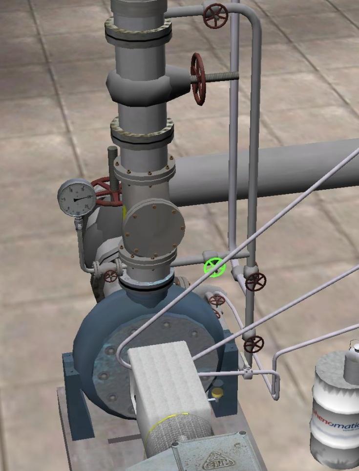
11 Simply navigate the cross-hairs onto the desired valve, switch, lever, etc and hold down the mouse button. On most equipment the rule is Left mouse button to open valves. Right mouse button to close valves. Or single click on the middle mouse button (or wheel) to fully-open or fully-close valves. 4.6 Menu mode (drop-down menus) Menu Mode (M mode) can be activated for every major piece of equipment. In M mode, the user can easily set-up various pre-determined situations (for example pump seizure, oil leak, or adjust oil levels, etc). To enter M Mode press space bar Select the required piece of apparatus from the tabs at the bottom of the screen Select which parameters are to be set, by choosing from the drop-down menu 11
12 Full navigation in the refinery is only restored when M Mode is quit (press Space again). 4.7 Visualizations For certain key equipment, it is possible to visualize the interior workings by selecting from the drop-down menus. This is dynamic real-time visualization: the visualization responds immediately to changes in the operating parameters which are set or triggered by the user. When it is no longer necessary to visualize a piece of equipment, the visualization should be de-selected in order to conserve computing power, and maximize the quality of the Petrospace user experience. Visualization of selected equipment can be triggered (drop-down menu): 12
13 (Press space for M Mode. Select desired equipment. Select/deselect visualization as appropriate. Select go-to for automatics transfer to equipment). Press space again to quit 5 Visualizations overview Pump G401A. Flow through the pump. Pump G401A. Mechanical seal. 13
14 Gas separator F404 at furnace Furnace B404 14

15 Distillation column D406 plus evaporator Distillation column D406 plus evaporator - detail 15
16 Steam trap Gas separator F5804 at gas reciprocating compressor 16
17 Gas reciprocating compressor G5814 first level chamber Gas reciprocating compressor G5814 plate valve 17

18 Heat exchanger E427A 6 Process pumps: demonstration examples Lubrication oil level (can be adjusted in M mode. Press Space. Select pump. Adjust Lubrication oil level. Space again to quit.) 18


19 Sealing oil level G401A, G401B, G414A, G414B Sealing oil level in pump G401 can be adjusted in M mode. Press Space. Select G401. Adjust sealing oil level. Space again to quit. Sealing oil pressure (all except G414) 19

")
20 Sealing oil pressure G414 Sealing oil temperature (G412A, G412B, G413A, G413B) 20


21 Suction pressure Suction valve open Delivery pressure 21


22 Delivery valve open Drainage closed (all pumps) 22

23 Pre-heating pipe closed (all) 23


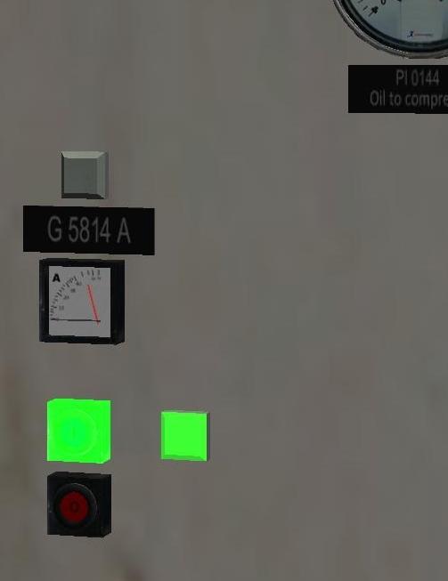
24 Pump start Ampere reading 24
 Leakage at the mechanical seal (triggered in M mode. Press Space.")
 The following can be triggered/adjusted (drop-down menu): (Press Space for")
25 Leakage at the flanges (triggered in M mode. Press Space. Select pump. Press filter congestion. Press space again to quit) Leakage at the mechanical seal (triggered in M mode. Press Space. Select pump. Press external leak. Press space again to quit) The following can be triggered/adjusted (drop-down menu): (Press Space for Trainer Mode. Select relevant pump. Select desired parameter). Space again to quit. 25
26 G401 Visualization when visualization on is selected from the drop-down menu, the flow of liquid through the pump is made visible (Pump G401 only) and the inner workings of the mechanical seal are visible. 26
27 Visualization of flow Visualization of mechanical seal 27


28 G412, G413, G414 G417 water pump Mechanical seal supply system The various mechanical seal supply systems function differently. Sealing oil system with pressure relay valve G401 28

29 Pressurized tandem mechanical seal G412 G413 Thermo-syphon sealing oil system G414 Virtual Refinery Trainer Manual The level and pressure of the mechanical seal supply system reacts automatically when there is a leak. Sealing oil system with pressure relay valve G401 The level of sealing oil can be adjusted in M mode for pump G401. Press space. select G401. Adjust sealing oil level. space again to quit. The sealing oil can be manually pumped from the reservoir to the sealing oil cylinder in the simulation as follows.. Opening valve 29


30 Pumping sealing oil from reservoir to cylinder Pressurized tandem mechanical seal G412 G413 The sealing oil level in the pump can be filled from the nearby trolley. 30


31 Opening blue refill cap Clicking on the trolley hose to connect 31


32 Opening the lever Pumping sealing oil from the trolley 32


33 Closing the lever Releasing the pressure in the hose before Disconnection of the hose. 33
34 Thermo-syphon sealing oil system G414 The procedure for filling the sealing oil is identical to that shown above for G412 and G413. Manometers Every manometer can be tested by means of the manometer lever. The correct operation of the manometer can be checked: with the valve leading to the manometer closed, the reading falls when the manometer lever is closed. The reading rises again after the manometer lever and the valve are opened again. 7 Refinery start-up top gas condensate steam top product cooling water inlet cooling water return bottom product feedstock fire ext. steam F 401 E 427 A E 427 B G 5814 F 411 E 430 B G 401 A E 430 A G 401 B D 406 G 412 A G 413 A F 5818 G 412 B G 413 B B 404 F 421 E 429 G 414 A Steam trap G 417 A G 417 B G 414 B Opening all lines from battery limit Follow the overhead pipes to locate the battery limit at the refinery perimeter or press Space, select battery limit and press go-to. Press space again to quit. 34


35 Opening the line feedstock from tank at the battery limit. Feedstock to distillation column After a few seconds there is a clearly-audible noise, and a rise of the pressures at the heat exchangers E 430 A/B and a rise in the suction pressure of the pump G 401. After opening of the feedstock line, 2 minutes are available to prepare the pump G 401 for start-up. If this time is exceeded, the buffer tank F 401 fills itself to 100%. When the pump G 401 is in use, the column D406 fills slowly. Within 2 minutes the sump pump G 414 must be taken into operation, otherwise the level in the column rises to 100%. The top product coming from the delivery side of G 413 A/B can be switched between the inlet pipe for use in tank F 401, or to the battery limit. 35
.")

36 To battery limit To tank F401 From pump G413 From heat exchanger E430 Triggering condensation: The user has to decide on the correct timing to trigger condensation (of top product). Top product appears in the tank F411 only after the user has selected trigger condensation in the distillation column drop-down menu. In the start-up Refinery Scenarios refinery running and refinery running except gas compressor, the condensation is already triggered. 8 Furnace B404 start-up In this simulation, there are both a furnace and an evaporator (E429) as distinct options. Normally, only one of these options would be present. 36


37 In the start-up Refinery Scenarios refinery stopped and refinery stopped except G401, the furnace may be started-up as below. In start-up Refinery Scenarios refinery running and refinery running except gas compressor, the furnace is already in operation. Quantity of the pump G 401 (above 4 ) 37

 Level in heating gas")
38 Furnace pressure: the exhaust gas flap being opened Virtual Refinery Trainer Manual Furnace pressure (in minus) Level in heating gas separator 38


39 Draining of gas separator The green lamp for the pilot gas is lit Pressing the pilot gas switch opens the main gas valve XV

 Each pilot")
40 The pilot burners being opened in sequence (upper levers) Each pilot burner is ignited. 40


41 When all 4 pilot burners are in operation, the green lamp heating gas lights in addition to pilot gas. Pressing the heating gas switch opens the main gas valve XV 402 The main burner valves are opened (lower levers). 41


42 Adjusting oxygen surplus and furnace pressure The user can inspect the flames via the inspection flap 42


43 Flame: blue and stable - optimal or see the flame condition from inside the furnace Flame: yellow, low and flickering too little air Flame: blue, unstable, flame rises too much air 43
: (Press Space for M Mode.")
 Press Space again to")
44 The following can be triggered/adjusted in M mode (drop-down menu): (Press Space for M Mode. Select Furnace B404. Set parameters required) Press Space again to quit. Visualization gas separator 44


45 Pipe burst (view inside furnace) Hot spot (view inside furnace) Burst pipe (fire) 45
 are not fulfilled whilst the furnace is in operation, then")

46 Forced Shutdown Virtual Refinery Trainer Manual If any of the conditions (interlocks) for start-up (quantity of pump G401, level in gas separator, furnace in under-pressure) are not fulfilled whilst the furnace is in operation, then this causes a forced shut-down of the furnace (automatic shut-off of gas valves XV401 and XV402). 9. Distillation column D406 Pressures, and liquid level in the column can be monitored. Column pressure (middle) Column pressure (top) 46

47 Liquid level. Evaporator For the evaporator to function, the valve steam to E429 must be open at the battery limit. Visualization Inner working of the column and evaporator can be visualized. Note that it will take about 60 seconds for the visualization to initialize after selecting it in M Mode. Three malfunctions can be activated: Overheating will overheat the bottom product which will then propagate slowly to the top of the column. This can be noticed by a growing percentage of brown spheres (bottom product) on each tray. Flood at sump will flood the column with liquid starting from the bottom. Flood at tray will flood the column with liquid starting at the second bubble cap tray. The following can be triggered (drop-down menu): (Press space for M Mode. Select Dist. Column. Select visualization on ) Press space again to quit 47

48 10. Steam trap Visualization column and evaporator The valve steam to E 429 at the battery limit must be open 48

49 inlet The inlet to the steam trap is open. Steam trap in normal operation (with visualization activated) 49
: (Press space for M mode. Select Steam Trap.")

50 Draining steam trap Steam hammering occurs when the trap is drained too much. The following can be triggered (drop-down menu): (Press space for M mode. Select Steam Trap. Set desired parameters) Press space again to quit. 11. Reciprocating gas compressor G5814 In start-up Refinery Scenario refinery running the gas compressor is already in operation. In all other start-up Refinery Scenarios, the gas compressor can be started-up as shown in the photos below. First - Check condensation at the column is active (and therefore gas is available): 50
 Press space again to quit Draining gas separator")
51 (Press space for M Mode. Select Distillation column D406. Select trigger condensation ) Press space again to quit Draining gas separator Opening suction valve 51


52 Opening delivery valve 52
 First")

53 Draining 1st and 2nd stage Draining cylinders (lantern housing) First stage. (Liquid levels can also be increased/decreased via the drop-down menu) 53
.")

54 Draining cylinders (lantern housing). Second stage (Liquid levels can also be increased/decreased via the drop-down menu) Oil pump on 54


55 Transmission oil level Bearing housing oil level 55


56 Drip feed lubrication level Drip feed lubrication manual turning 56


57 Valves loaded to zero Manual turning of the compressor 57


58 Control panel: alarm lamps off Control panel: oil pressure OK Switching oil filters 58

59 Compressor start Power usage 59


60 Oil pump to Auto Loading first stage 60

61 Loading second stage The following table shows settings for loading the compressor 1. stage 2. stage flow rate adding valve S1 S2 S3 S4 flow rate 100% R L L L L 100% 85% L L L L L 85% 50% L R L R L 50% 35% L L R R L 35% 0% L R R R R 0% S1 to S4 suction valve 1 to suction valve 4 R L turn valve right (no flow rate) turn valve left Concluding checks of the compressor: Gas leakage check Oil leakage check Noise check 61


62 Bearing housing temperature check Temperature at 2nd stage Check of temperature of pressure valve 2nd level 62


63 Transmission oil temperature Lubricator oil pressure 63


64 Bearing housing oil pressure Transmission oil pressure Level of gas separator 64

65 The following can be triggered (drop-down menu): (Press space for M mode. Select Gas compressor. Set desired parameters) Press space again to quit 65

66 Visualizations Gas separator if overfilled, forced shutdown of the gas compressor occurs. First level chamber 66


67 Gas flow through the compressor Plate valve 67
: (Press space for M Mode.")
68 Gas leak 12. Heat exchanger E427, E430 Visualization can be triggered for E427 (drop-down menu): (Press space for M Mode. Select Heat exchanger E427. Select visualization ) Press space again to quit Visualization of inner working 68
:")
 Press space again to quit.")
69 13. Gas separator F404, F5804 Liquid level can be monitored and drained Visualization of the gas separators can be triggered (drop-down menu): (Press space for M Mode. Select Furnace or Gas Compressor. Set visualization of gas separator) Press space again to quit. Inner working can be visualized. 69


")
70 Gas separator F5804 (at the gas compressor) Gas separator F404 (at the furnace) Flooding of gas separator F404 (at the furnace) 70


71 14. Tank F401 Liquid level monitoring Pressure monitoring 71


72 15. Control valves The water separator can be drained Control Valves throughout the refinery can be drained, monitored, bypassed. 16. Battery limit 72
 different types of")

73 Valves on all inlet pipes to the refinery can be open/closed. 17. Personal safety equipment In the equipment room (press h or home ) different types of protective clothing and personal equipment can be viewed, and their purpose explained Hard hat Hard hat with visor Safety glasses Gas Mask Escape filter Gas warning devices Walkie-talkie 73
74 Leather gloves Rubber gloves 18. Software trouble shooting Visualizations Visualizations require substantial computing power, so you should activate only one visualization at a time and give the simulation a few seconds to initialize itself and create equilibrium. Initialization Some visualizations need time to initialize themselves correctly and reflect the true state of the apparatus after they have been activated. The following table lists the visualizations and the maximum time it takes for them to reflect the true state of the apparatus after activation: apparatus/visualization maximum time for initialization Pump G401A 5 seconds Furnace inside - Steam trap 5 seconds Distillation column and evaporator 60 seconds Heat exchanger E427 - Gas compressor (gas flow visualization) 5 seconds Gas separator 7 seconds Graphics/Speed We recommend using Petrospace with a screen resolution between 1024 x 768 and 1920 x It will run on higher resolutions, but this will put more strain on your graphics card. It will also work with lower resolutions, but you may experience problems using all functions in the menu mode. It is recommended to close all other applications before starting Petrospace. Fullscreen vs. windowed mode Petrospace will always start in full screen on your primary display. If you need to switch to a different application (e.g. your client) during your Petrospace session, you can press the f key (fullscreen) to switch to a windowed mode. However, Petrospace can t be operated correctly in windowed mode. To switch back to fullscreen, move your mouse into the Petrospace window (and click the left mouse button to set the Windows focus on Petrospace) and press f again. General measures to improve graphics speed 74
75 If Petrospace runs jerky or is too slow, you can try switching to a lower screen resolution. Petrospace will always use the current resolution of your Windows desktop. You can change the screen resolution before starting Petrospace using the software utilities of the graphics driver (e.g. NVIDIA Control Panel, AMD/ATI Catalyst Control Center) or the System Settings of Windows. Please note that Petrospace requires at least 1204 x 768 pixels to operate correctly. It will run on lower resolutions, but you might not be able to use all functions in the menu mode. Jerky motion It is normal to experience short stops or jerky motion at the beginning of the simulation, especially when you look into a direction for the first time. This is because Petrospace must load graphics data into the graphics memory. You should not experience stops or jerky motion after this. If you experience jerky motion permanently, it is likely that the PC on which you are running Petrospace is not powerful enough for the simulation. Flashes/Missing background textures If you experience flashing surfaces or a black background instead of a sky and refinery panorama, it s likely that the graphics card of the PC on which you are running Petrospace lacks sufficient graphics memory. Try switching to a lower screen resolution (note that 1024 x 768 is the lowest recommended resolution for Petrospace) or install Petrospace on a different PC. You will need at least 128MB of graphics memory to run Petrospace in a resolution of 1024 x 768 pixels. The application is frozen and will not react to any mouse or keyboard input In rare cases Petrospace might freeze. This is most likely because of limited resources on your PC or because the PC is not powerful enough to run Petrospace. In this case you will need to hold down the keys Cntrl+Alt+Del at the same time to start the Process Monitor of Windows where you can click on Petrospace and select Kill process. You can also try pressing Alt+Tab to switch to the console window of Petrospace and close this window. Please close all applications running on your PC before starting Petrospace the next time. Missing pipe bends or small details If small details or pipe bends (in the distance) will not show, it means that your PC (i.e. your graphics card) is not powerful enough to display all details at the same time. In this case Petrospace will discard small features and details (e.g. parts of pipes in the distance) to try to enable a smooth operation. If you get closer to an object it will display correctly. You may try to switch to a lower screen resolution to avoid this effect. No sound 75
76 Please check that sound isn t turned off in the Windows Control Panel and check if you can hear standard systems sounds. If only Petrospace is silent, then you can try the following: 1. Go to the Petrospace install directory (e.g. C:\Program Files\Phenomatics\Petrospace ) 2. Go into the subdirectory bin and further into config 3. Locate the file bonfire.cfg and open it in the Windows Notepad 4. Locate the line sound_device "Generic Hardware" 5. Put two slashes at the beginning of this line so that it reads //sound_device "Generic Hardware" 6. Locate the line //sound_device "Generic Software" 7. Remove the two slashes so that it reads sound_device "Generic Software" 8. Start Petrospace 76
Armfield Distillation Column Operation Guidelines
 Armfield Distillation Column Operation Guidelines 11-2016 R.Cox Safety SAFETY GLASSES ARE REQUIRED WHEN OPERATING THE DISTILLATION COLUMN Wear gloves when mixing alcohol feedstock The column will become
In Response to a Planned Power Outage: PPMS EverCool II Shut Down and Re-start Procedure
 PPMS Service Note 1099-412 In Response to a Planned Power Outage: PPMS EverCool II Shut Down and Re-start Procedure Introduction: Loss of electricity to the PPMS EverCool II should not cause damage to
1. Study the performance of a binary distillation column operated in batch mode.
 Goals for batch distillation using the East distillation column: 1. Study the performance of a binary distillation column operated in batch mode. 2. Determine the overall and local efficiency of the column
FRDS GEN II SIMULATOR WORKBOOK
 FRDS GEN II SIMULATOR WORKBOOK Trotter Control Inc 2015 Document# Revision Revised 9001-0038 FRDS GEN II Simulator Workbook E 02/15/2015 by DC FRDS GEN II Simulator Workbook This workbook is a follow-on
Operating Instructions
 Operating Instructions Preparation for Start-up 1. If the computer system is logged off, log into the computer system. Log into the operator account on the computer. Please ask your TA for username and
Manual for continuous distillation
 Manual for continuous distillation 1. Week 1: Objectives: Run the column at total reflux. When steady state is reached, take the sample from the top and bottom of the column in order to determine the overall
Quick Start Guide. For Gold and Silver Editions
 Quick Start Guide For Gold and Silver Editions Table of Content Introduction... 3 Prerequisites... 3 Installation and Setup... 4 Download and Install QQEvolution 2... 4 Create Users... 8 Create Agent/CSR/Producer...
ANNEX AMENDMENTS TO THE INTERNATIONAL CODE FOR FIRE SAFETY SYSTEMS (FSS CODE) CHAPTER 15 INERT GAS SYSTEMS
 CHAPTER 15 INERT GAS SYSTEMS") Annex 3, page 2 ANNEX AMENDMENTS TO THE INTERNATIONAL CODE FOR FIRE SAFETY SYSTEMS (FSS CODE) CHAPTER 15 INERT GAS SYSTEMS The text of existing chapter 15 is replaced by the following: "1 Application This
Annex 3, page 2 ANNEX AMENDMENTS TO THE INTERNATIONAL CODE FOR FIRE SAFETY SYSTEMS (FSS CODE) CHAPTER 15 INERT GAS SYSTEMS The text of existing chapter 15 is replaced by the following: "1 Application This
Instruction Manual. BZ7002 Calibration Software BE
 Instruction Manual BZ7002 Calibration Software BE6034-12 Index _ Index Index... 2 Chapter 1 BZ7002 Calibration Software... 4 1. Introduction... 5 Chapter 2 Installation of the BZ7002... 6 2. Installation
CONSUMER MODEL INSTALLATION GUIDE
 CONSUMER MODEL INSTALLATION GUIDE System requirements Windows System Requirements To use your TOMI and its software, your system should have: A Microsoft Windows compatible PC with a Pentium IV processor
PC Configuration software for Discovery MkVI v 1.03 User guide
 PC Configuration software for Discovery MkVI v 1.03 User guide This user guide describes the different features included in PC Config software, version 1.03, and how they are used. When referring to this
User Manual for the Mars Calibration Bench
 User Manual for the Mars Calibration Bench Fall 2013 Table of Contents Table of Contents Table of Contents... iii Introduction... v Chapter 1: The Mars Calibration Bench... 1 What Is the Mars Calibration
Burner Management System DEMO Operating instructions
 Burner Management System DEMO Operating instructions Burner Management System DEMO Operating Instructions Startup Summary - Normal startup is accomplished in four basic steps: 1. Leak Test a. Safety Valve
ELIMINATOR COMPETITION DRAG RACE Program Manual Firm Ver 4.11
 ELIMINATOR COMPETITION DRAG RACE Program Manual Firm Ver 4.11 The Portatree Eliminator Super 2000 Competition Track Timer can be used with an IBM Compatible Personal Computer connected through Com Port
Technology. In the My Files [My Files] submenu you can store all the programs that you have made on the NXT or downloaded from your computer.
![Technology. In the My Files [My Files] submenu you can store all the programs that you have made on the NXT or downloaded from your computer.](/thumbs/74/70002303.jpg "Technology. In the My Files [My Files] submenu you can store all the programs that you have made on the NXT or downloaded from your computer.") NXT Main Menu My Files Files are automatically placed into the appropriate folders. When you download a program using a Sound file to the NXT, the program will be placed under Software files while the
NXT Main Menu My Files Files are automatically placed into the appropriate folders. When you download a program using a Sound file to the NXT, the program will be placed under Software files while the
OWNER S TECHNICAL MANUAL
 EL SERIES OWNER S TECHNICAL MANUAL DP7002 1 Air Operated Diaphragm Pump Description The DP7002 1 air operated diaphragm pump is the ideal device for the pumping, transfer and dispensing of chemical liquids,
A TECHNICAL REFERENCE
 A TECHNICAL REFERENCE FOR CAREL DCM CONTROLLERS DIGITAL COMPRESSOR MODULE CANADIAN HEAD OFFICE AND FACTORY USA HEAD OFFICE AND FACTORY CANADIAN EASTERN FACTORY 1401 HASTINGS CRES. SE CALGARY, ALBERTA T2G
Quick Start Guide. A. Hardware installation B. Software installation C. Start the software for the first time D. Do your first measurement
 Quick Start Guide This Quick Start Guide describes the hardware and software installation process and the Measurement feature in a simple way. Please follow the sequence of the steps to avoid problems
ATL R/V Atlantis AUXILIARY PLANT OPERATION APPENDIX OPERATING PROCEDURES
 110 AIR CONDITIONING CHILLED WATER PLANT 1. Ensure power to water chiller controller and all fan coil unit controllers is on 2. Ensure chilled water expansion tank level is at its proper level 3. Ensure
Perfect Golf Quick Start Guide
 Quick Start Guide Perfect Golf Quick Start Guide To play Perfect Golf you must first have purchased the following: 1. A SkyTrak Launch Monitor 2. Have an active Play and Improve Package 3. Have purchased
Air Tractor Preventative Maintenance Manual And Troubleshooting
 1.0 Overview This maintenance schedule will assist in the maintenance and troubleshooting procedures for the Unified Industries Air Tractor. The first portion of this section details the general maintenance
Unit 24: Applications of Pneumatics and Hydraulics
 Unit 24: Applications of Pneumatics and Hydraulics Unit code: J/601/1496 QCF level: 4 Credit value: 15 OUTCOME 2 TUTORIAL 9 ACCUMULATORS The material needed for outcome 2 is very extensive so there are
WF STEUERUNGSTECHNIK GMBH. INFORMATION and TECNICAL DESCRIPTION
 1 INFORMATION and TECNICAL DESCRIPTION 14 2 AIRLEADER Professional Compressor Management + Compressed Air Visualisation + Alarm Service Management + AIRLEADER - has been the effective answer for compressed
RM-80 respiration monitor
 RM-80 respiration monitor User Manual September 18, 2015 0025-003M 950 North Hague Avenue Columbus, Ohio 43204-2121 USA Sales: sales@colinst.com Service: service@colinst.com Phone: (614) 276-0861 Fax:
FireHawk M7 Interface Module Software Instructions OPERATION AND INSTRUCTIONS
 FireHawk M7 Interface Module Software Instructions OPERATION AND INSTRUCTIONS WARNING THE WARRANTIES MADE BY MSA WITH RESPECT TO THE PRODUCT ARE VOIDED IF THE PRODUCT IS NOT USED AND MAINTAINED IN ACCORDANCE
FAULT CODE TROUBLESHOOTING INDEX
 FAULT CODE TROUBLESHOOTING INDEX 1. Display indicates Change Filters 2. Display indicates Drip Tray Full Continuous Alarm will Sound 3. Display indicates Cold Fault 4. Display indicates Hot Fault 5. Display
444C DUAL PERFORMANCE VALUE PACK
 (Chrome) PART NO. 44432 IMPORTANT: It is essential that you and any other operator of this product read and understand the contents of this manual before installing and using this product. SAVE THIS MANUAL
Cover Page for Lab Report Group Portion. Head Losses in Pipes
 Cover Page for Lab Report Group Portion Head Losses in Pipes Prepared by Professor J. M. Cimbala, Penn State University Latest revision: 02 February 2012 Name 1: Name 2: Name 3: [Name 4: ] Date: Section
42045 Heavy Duty ADA Base Model Kit: 85/105 PSI (ADA Compressor Only) Heavy Duty ADA Base Model Kit: 110/145 PSI (ADA Compressor Only)
 Heavy Duty ADA Base Model Kit: 110/145 PSI (ADA Compressor Only)") 42045 Heavy Duty ADA Base Model Kit: 85/105 PSI (ADA Compressor Only) 42047 Heavy Duty ADA Base Model Kit: 110/145 PSI (ADA Compressor Only) 45052 Constant Duty ADA Base Model Kit: 85/105 PSI (ADA Compressor
42045 Heavy Duty ADA Base Model Kit: 85/105 PSI (ADA Compressor Only) 42047 Heavy Duty ADA Base Model Kit: 110/145 PSI (ADA Compressor Only) 45052 Constant Duty ADA Base Model Kit: 85/105 PSI (ADA Compressor
400C & 450C DUAL PERFORMANCE VALUE PACKS
 (Chrome) PART NO. 40013 (Silver) PART NO. 45012 (Chrome) PART NO. 45013 IMPORTANT: It is essential that you and any other operator of this product read and understand the contents of this manual before
Table of Content IMPORTANT NOTE: Before using this guide, please make sure you have already set up your settings in
 Quick Start Guide Table of Content Introduction... 3 Prerequisites... 3 How to Open QQEvolution 2... 4 How to do Carrier Downloads... 5 Locating a Client in QQEvolution 2... 7 Adding a New Client... 8
Industrial Pneumatics
 Industrial Pneumatics Industrial Training Manual 1 Level 1 Version 3.0 April 2015 This manual was developed for use with the following products: FluidSIM Pneumatics 5.0 English DEPCO Pneumatics Training
Digester Processes. 1. Raw Sludge Pumping System
 Digester Processes 1. Raw Sludge Pumping System Removes accumulated sludge from the primary clarifiers, pumped through 1 of 2 pipes either 150 or 200mm in diameter (Fig. 1.1). Fig 1.1 Pipes feeding Digesters
Release: 1. UEPOPL002A Licence to operate a reciprocating steam engine
 Release: 1 UEPOPL002A Licence to operate a reciprocating steam engine UEPOPL002A Licence to operate a reciprocating steam engine Modification History Not applicable. Unit Descriptor Unit Descriptor 1)
User Manual 1 P a g e Rev. V1.6-EN 11/08/2014
 User Manual 1 P a g e Rev. V1.6-EN 11/08/2014 Copyright Disclaimer Trademarks and patents Intended use Contact info 2011 Inflotrolix, Inc. This document may not be copied in whole or in part or otherwise
XC2 Client/Server Installation & Configuration
 XC2 Client/Server Installation & Configuration File downloads Server Installation Backup Configuration Services Client Installation Backup Recovery Troubleshooting Aug 12 2014 XC2 Software, LLC Page 1
OPERATION MANUAL NTF-15
 OPERATION MANUAL NTF-15 Nitrogen Tire Filling Valve Stem Caps (Qty=200) Order P/N 436075 RTI Technologies, Inc 10 Innovation Drive York, PA 17402 800-468-2321 www.rtitech.com 035-81235-00 (Rev B) TABLE
OPERATION MANUAL NTF-60 Plus
 OPERATION MANUAL NTF-60 Plus Nitrogen Tire Filling Valve Stem Caps (Qty=200) Order P/N 436075 RTI Technologies, Inc 10 Innovation Drive York, PA 17402 800-468-2321 www.rtitech.com 035-81264-00 (Rev A)
Water Mist Systems Inspection, Testing, and Maintenance of Water Mist Systems
 Water Mist Systems Inspection, Testing, and Maintenance of Water Mist Systems Name of Property: Address: Phone Number: Inspector: Contract No.: Date: This Report Covers: Monthly Quarterly Annual Other
Software for electronic scorekeeping of volleyball matches, developed and distributed by:
 Software for electronic scorekeeping of volleyball matches, developed and distributed by: Developed for the rules of USports 2017-18 As adopted by Ontario University Athletics for Men s & Women s Volleyball
200 PSI COMPRESSORS - MODEL NUMBERS
 200 PSI COMPRESSORS - MODEL NUMBERS 380C AIR COMPRESSOR KIT PART NO. 38033 480C AIR COMPRESSOR KIT PART NO. 48043 380C 480C IMPORTANT: It is essential that you and any other operator of this product read
100C Air Compressor Kit
 10010 100C Air Compressor (standard mounting bracket, CE Spec) 10014 100C Air Compressor (no leader hose or check valve, CE Spec) 10016 100C Air Compressor (with Omega Bracket, CE Spec) IMPORTANT: It is
product manual HM-4140, HM-4150, HM-4160 HM-4160A HM-4150 Humboldt FlexPanels
 12.09 product manual HM-4140, HM-4150, HM-4160 HM-4160A HM-4150 Humboldt FlexPanels Introduction: This manual covers the installation and operation of Humboldt FlexPanels for Triaxial and Permeability
GAS DEHYDRATION SYSTEM
 GAS DEHYDRATION SYSTEM High pressure gases from the Gas Compressors (CBA-4070/4020) flow to the Glycol Contactor (MAF-1150). In the Contactor, gas flows through trays, contacting the lean glycol that is
v2.3 USER MANUAL
 v2.3 USER MANUAL www.foresightsports.com Table of Contents 03 04 05 09 12 17 20 21 Activation Getting Started Play Compete Improve Settings Update Manager Glossary 04 11 05 12 03 Activation FSX Activation
IVIS Spectrum Whole Animal Imager
 IVIS Spectrum Whole Animal Imager Kyle Marchuk Adam Fries Jordan Briscoe Taylor Shagam July 2018 Contents 1 Introduction 2 2 Hardware - Startup 4 3 Start-Up Software 5 4 Shut Down 11 1 1 Introduction The
Microsoft Windows Software Manual for FITstep Stream Version 4
 Thank you for purchasing this product from Gopher. If you are not satisfied with any Gopher purchase for any reason at any time, contact us and we will replace the product, credit your account, or refund
OPERATION MANUAL RTI RHS650 RTI TECHNOLOGIES, INC East Market Street York, PA Manual P/N
 OPERATION MANUAL RTI RHS650 RTI TECHNOLOGIES, INC. 4075 East Market Street York, PA 17402 Manual P/N 035-80589-02 Table of Contents Components... 2 Test... 4 Recovery/Recycling... 5 Evacuation... 7 Charging...
WATER CONTROL SYSTEM QUICK START
 SETTINGS MENU SYSTEM OPTIONS WATER LEVEL BAR GRAPH 3 DS SPRAY ON/OFF CS SPRAY ON/OFF BEACON WATER CONTROL SYSTEM QUICK START WWW.GFWORLDWIDE.COM +1 (208) 664-9291 SERVICE@GFWORLDWIDE.COM DISPLAY SCREEN
FX134, FX1234, FX3030 Problem and Solutions
 FX134, FX1234, FX3030 Problem and Solutions Unit Will Not Power Up Turn the power switch on. The unit LCD will display revision program and filter life within 3 to 5 seconds after turning on unit. If this
MULTITUBE BUBBLE TUBE BY ROMPA (U)
") Page 1 of 16 MULTITUBE BUBBLE TUBE BY ROMPA 19781 (U) CONTENTS 1 x Base Unit (chassis) 1 x Base Cover (white plastic cover) 1 x Multitube Bubble Tube Column 1 x Bubble Tube Cap 1 x Power Supply (black
Page 1 of 16 MULTITUBE BUBBLE TUBE BY ROMPA 19781 (U) CONTENTS 1 x Base Unit (chassis) 1 x Base Cover (white plastic cover) 1 x Multitube Bubble Tube Column 1 x Bubble Tube Cap 1 x Power Supply (black
AKTA pure 25 New Owner s Intro
 AKTA pure 25 New Owner s Intro The exercise below will give a quick demonstration of how easy and intuitive the AKTA pure 25 will be for you in demonstrating downstream processing to your students. Steps
P-03 MAINTENANCE MECHANIC TRAINING SKILL DEVELOPMENT GUIDE
 P-03 MAINTENANCE MECHANIC TRAINING SKILL DEVELOPMENT GUIDE Duty P: Steam Systems P-03: Perform Startup and Shutdown Procedures Issued 01/01/99 Perform Startup and Shutdown Procedures Task Preview Startup
450P AUTOMATIC PORTABLE COMPRESSOR EXTREME SERIES
 EXTREME SERIES PART NO. 45043 IMPORTANT: It is essential that you and any other operator of this product read and understand the contents of this manual before installing and using this product. SAVE THIS
FLUID POWER FLUID POWER EQUIPMENT TUTORIAL ACCUMULATORS. This work covers part of outcome 2 of the Edexcel standard module:
 FLUID POWER FLUID POWER EQUIPMENT TUTORIAL ACCUMULATORS This work covers part of outcome 2 of the Edexcel standard module: UNIT 21746P APPLIED PNEUMATICS AND HYDRAULICS The material needed for outcome
Installation Operation Maintenance. Bermad Level Control Valve with Modulating Horizontal Float Pilot valve One Way Flow IOM.
 Bermad Level Control Valve with Modulating Horizontal Float Pilot valve One Way Flow Model: FP 450-80 Installation Operation Maintenance PAGE 1 OF 5 1. Safety First BERMAD believes that the safety of personnel
AUTOMATIC HOSE TEST UNIT, TYPE SPU
 VALVES AND FITTINGS UP TO 14,000 BAR TEST AND CONTROL EQUIPMENT H IGH PRESSURE TECHNOLOGY AUTOMATIC HOSE TEST UNIT, TYPE SPU Pressure range from 1 up to 10,000 bar User-friendly touch panel operation HIGH-PRESSURE
Safety instructions and operating manual
 5-Master Safety instructions and operating manual TBF-PyroTec GmbH Lichterfelder Str. 5 A 21502 Geesthacht Tel.: + 49 (0)4152 157 9950 Fax: + 49 (0)4152 157 9951 Flame projector 5-Master Safety instructions
AIR COMPRESSOR OPERATING INSTRUCTION AND PARTS LIST
 AIR COMPRESSOR OPERATING INSTRUCTION AND PARTS LIST OIL-LESS TYPE IMPORTANT: PLEASE READ CAREFULLY BEFORE STARTING OPERATIONS. THE CONTENTS ARE FOR GENERAL INFORMATION OF ALL THE SIMILAR MODELS. Record
GA-300 Gas Analyzer. Technical Note. Overview. Front Panel. iworx Systems, Inc. GA-300
 Technical Note GA-300 Overview The GA-300 CO2 and O2 Gas Analyzer is easy to use, robust, and adaptable to human, animal, and plant applications. The GA-300 has two analog outputs to allow recording and
LED CONVERSION BOARD - YAKUZA SERIES EGO/GEO
 LED CONVERSION BOARD - YAKUZA SERIES EGO/GEO The LED conversion board replaces the OLED screen mini-board on your Yakuza Series board. Combined with new firmware, your board will function similarly to
MODEL NUMBER: P-A AUTOMATIC PORTABLE COMPRESSOR
 MODEL NUMBER: 45043-450P-A AUTOMATIC PORTABLE COMPRESSOR IMPORTANT: It is essential that you and any other operator of the product read and understand the contents of this manual before installing and
M-06 Nitrogen Generator (Nitrogen Making Machine)
") Guideline No.M-06 (201510) M-06 Nitrogen Generator (Nitrogen Making Machine) Issued date: 20 th October, 2015 China Classification Society Foreword This Guideline is a part of CCS Rules, which contains
Guideline No.M-06 (201510) M-06 Nitrogen Generator (Nitrogen Making Machine) Issued date: 20 th October, 2015 China Classification Society Foreword This Guideline is a part of CCS Rules, which contains
420C AIR COMPRESSOR KIT PART NO C AIR COMPRESSOR KIT PART NO
 420C AIR COMPRESSOR KIT PART NO. 42042 460C AIR COMPRESSOR KIT PART NO. 46043 420C 460C IMPORTANT: It is essential that you and any other operator of this product read and understand the contents of this
Race Screen: Figure 2: Race Screen. Figure 3: Race Screen with Top Bulb Lock
 Eliminator Competition Stand Alone Mode - Instruction Manual Main Menu: After startup, the Eliminator Competition will enter the Main Menu. Press the right/left arrow buttons to move through the menu.
BASIC Z-STACK AND TIME SERIES SCAN ON THE ZEISS LIGHTSHEET Z. 1
 BASIC Z-STACK AND TIME SERIES SCAN ON THE ZEISS LIGHTSHEET Z. 1 The front door of the main body of the instrument may be open when you arrive. Take the sample chamber and slide it into position with the
The Univentor 1250 Anaesthesia Unit
 THE UNIVENTOR 1200/1250 ANAESTHESIA UNIT The Univentor 1250 Anaesthesia Unit TABLE OF CONTENTS EDITION 1 Section 1 - WARRANTY & SERVICE 1.1. WARRANTY 2 1.2. DAMAGED SHIPMENTS 2 1.3. SERVICE 2 Section 2
New product release. Universal Rebreather Monitor (URBM) Three cell / Independent backup
 Three cell / Independent backup") New product release Closed Circuit Research is pleased to announce the launch of our range of Universal Rebreather Monitors Universal Rebreather Monitor (URBM) Three cell / Independent backup Key features
New product release Closed Circuit Research is pleased to announce the launch of our range of Universal Rebreather Monitors Universal Rebreather Monitor (URBM) Three cell / Independent backup Key features
UNIVERSITY OF WATERLOO
 UNIVERSITY OF WATERLOO Department of Chemical Engineering ChE 524 Process Control Laboratory Instruction Manual January, 2001 Revised: May, 2009 1 Experiment # 2 - Double Pipe Heat Exchanger Experimental
UNIVERSITY OF ROCHESTER ENVIRONMENTAL HEALTH & SAFETY
 Revision No.: 1 Page 1 of 6 I. PURPOSE This policy/procedure establishes the proper steps for set up, and operation of the BullEx I.T.S Xtreme training system. II. PERSONNEL AFFECTED Fire Safety staff
SSI Solaris 150 RTA Revision /27/2016 Page 1 of 9. SSI Solaris 150 RTA
 Page 1 of 9 SSI Solaris 150 RTA The Solaris 150 RTA is a rapid thermal annealing system capable of handling sample sizes up to 100mm (4 diameter) or smaller. The system can anneal in N 2 and Forming gas
Locator Locator-D-Lux Air-Saver G1 Air-Saver G2
 170663_air_saving_products 17-02-2011 16:42 Pagina 1 Locator Locator-D-Lux Air-Saver G1 Air-Saver G2 AIR SAVING PRODUCTS 170663_air_saving_products 17-02-2011 16:42 Pagina 2 170663_air_saving_products
Procedures for operation of the TA Instruments DSC
 Procedures for operation of the TA Instruments DSC Purpose and Scope: This document describes the procedures and policies for using the MSE TA Instruments DSC. The scope of this document is to establish
Software Manual for FITstep Pro Version 2
 Thank you for purchasing this product from Gopher. If you are not satisfied with any Gopher purchase for any reason at any time, contact us and we will replace the product, credit your account, or refund
USA Jump Rope Tournament Software User Guide 2014 Edition
 USA Jump Rope Tournament Software User Guide www.usajumprope.org Table of Contents Contents System Requirements... 3 System Conventions... 4 Phase 1 Tournament Pre registration Preparation... 5 Name Your
GAS DEHYDRATION SYSTEM
 GAS DEHYDRATION SYSTEM High pressure and compressed gases flow to the Glycol Contactor (MAF-3110). In the Contactor, gas flows through trays, contacting the lean glycol that is flowing across the trays
Model PSI Compressor with 3-Gallon Air Tank 12VDC
 Model 6350 150 PSI Compressor with 3-Gallon Air Tank 12VDC IMPORTANT: It is essential that you and any other operator of this product read and understandd the contents of this manual before installing
Guideline No.M-05(201510) M-05 AIR COMPRESSOR. Issued date: 20 October China Classification Society
 M-05 AIR COMPRESSOR. Issued date: 20 October China Classification Society") Guideline No.M-05(201510) M-05 AIR COMPRESSOR Issued date: 20 October 2015 China Classification Society Foreword This Guideline constitutes the CCS rules, and establishes the applicable technical requirements
Guideline No.M-05(201510) M-05 AIR COMPRESSOR Issued date: 20 October 2015 China Classification Society Foreword This Guideline constitutes the CCS rules, and establishes the applicable technical requirements
Method Statement: Testing Dry Riser System
 Method Statement: Testing Dry Riser System Page 1 of 6 Scope of work Test dry riser system in accordance with BS 5306. Definitions For the purposes of this document, the following definitions apply Rising
The ICC Duckworth-Lewis-Stern calculator. DLS Edition 2016
 The ICC Duckworth-Lewis-Stern calculator DLS Edition 2016 (DLS2-2016) Installation and operating instructions Queries about program operation should be sent to: Steven.Stern@qut.edu.au 2016 International
1)! DO NOT PROCEED BEYOND THIS MARK
! DO NOT PROCEED BEYOND THIS MARK") Operating Instructions for X-ray Photoelectron Spectrometer: Physical Electronics Model 555 XPS/AES (John H. Thomas, III, Ph.D., Electron Spectroscopy) Sample Insertion: figure 1. Sample insertion rod
Operating Instructions for X-ray Photoelectron Spectrometer: Physical Electronics Model 555 XPS/AES (John H. Thomas, III, Ph.D., Electron Spectroscopy) Sample Insertion: figure 1. Sample insertion rod
The HumiSys. RH Generator. Operation. Applications. Designed, built, and supported by InstruQuest Inc.
 The HumiSys RH Generator Designed, built, and supported by InstruQuest Inc. Versatile Relative Humidity Generation and Multi-Sensor System The new HumiSys with single or dual RH probes capabilities is
JETFIRST 150 RTA SYSTEM OPERATING MANUAL Version: 2 Feb 2012
 JETFIRST 150 RTA SYSTEM OPERATING MANUAL Version: 2 Feb 2012 UNIVERSITY OF TEXAS AT ARLINGTON Nanofabrication Research and Teaching Facility TABLE OF CONTENTS 1. Introduction....2 1.1 Scope of Work.....2
Hi-Force Limited Prospect Way Daventry Northants NN11 8PL United Kingdom Tel: +44(0) : Fax: +44(0) : Website:
 : Fax: +44(0) : Website:") 1.0 Inspection of the product upon receipt: On receipt of the product, visually inspect the item for any evidence of shipping damage. Please note shipping damage is not covered by warranty. If shipping
1.0 Inspection of the product upon receipt: On receipt of the product, visually inspect the item for any evidence of shipping damage. Please note shipping damage is not covered by warranty. If shipping
PC1131 Electric Air Compressor
 Senco Products Inc. 8485 Broadwell Road Cincinnati, Ohio 45244 PC1131 Electric Air Compressor Operating Instructions C US 2006, 2007 by Senco Products, Inc. Warnings for the safe use of this tool are included
Model: 43T. Bermad Pressure Relief Valve
 Model: 43T Bermad Pressure Relief Valve Installation Operation Maintenance Manual () Rev.C1_01.08.17 Page 1 of 10 Safety First BERMAD believes that the safety of personnel working with and around our equipment
Napa Technology Trouble Shooting. For Premier & Premier PLUS Models
 Napa Technology Trouble Shooting For Premier & Premier PLUS Models Before contacting Napa Technology for support, please check if the problem and solution are found below: Machine Is Off & All LCD s are
PERFORM Operating Document
 PERFORM Operating Document Use and Maintenance of CO 2 Incubator PC-POD-CA-007-v03 Revision History Version Reason for Revision Date 01 New POD 30-Sep-13 02 Minor revisions for section 2.3, 3.1, 4.3. 14-April-16
Code AWC20HP Air Compressor
 Code 951816 AWC20HP Air Compressor Index of Contents Index of Contents 02 Declaration of Conformity 02 What s Included 03 Safety Precautions 03 Specifications (AWC20HP Air Compressor) 04 Assembly Instructions
MASK INTEGRITY TEST ACCESSORY (MITA) MODEL 8120
 MODEL 8120") MASK INTEGRITY TEST ACCESSORY (MITA) MODEL 8120 QUICK START GUIDE P/N 6006154, REVISION C MAY 2013 Model 8120 Mask Integrity Tester is patented under U.S. Patent No. 8,312,761. Additional patents are pending.
MASK INTEGRITY TEST ACCESSORY (MITA) MODEL 8120 QUICK START GUIDE P/N 6006154, REVISION C MAY 2013 Model 8120 Mask Integrity Tester is patented under U.S. Patent No. 8,312,761. Additional patents are pending.
Superconducting Susceptometer (MPMS-5S) Quantum Design Room 296 (MPMS)
 Quantum Design Room 296 (MPMS)") Superconducting Susceptometer (MPMS-5S) Quantum Design Room 296 (MPMS) Sensitivity: 1x10 11 A m 2 Applied DC fields: 0 T to 5 T Applied AC fields: 0 G to 3 G (zero-to-peak), 0.01 Hz to 1000 Hz Temperatures
Superconducting Susceptometer (MPMS-5S) Quantum Design Room 296 (MPMS) Sensitivity: 1x10 11 A m 2 Applied DC fields: 0 T to 5 T Applied AC fields: 0 G to 3 G (zero-to-peak), 0.01 Hz to 1000 Hz Temperatures
Equipment Operating Procedure Glove Box
 Equipment Operating Procedure Glove Box Page 1 0.0 Changing the Compressed Gas Cylinder 1. Complete Compressed Gas Cylinder training from EHS website before manually exchanging gas cylinders. In order
Operating instructions Electrical switching facility pco
 Operating instructions Electrical switching facility pco from software version V1.33 on TABLE OF CONTENTS 1. Before you start... 4 1.1 Brief description... 4 1.2 Using this manual... 4 2. pco integrated
IMPORTANT SAFETY INSTRUCTIONS
 IMPORTANT SAFETY INSTRUCTIONS CAUTION - To reduce risk of electrical shock: - Do not disassemble. Do not attempt repairs or modifications. Refer to qualified service agencies for all service and repairs.
OPTIMA 7 - BIOGAS Calibrating the gas sensors SENSOR ADJUSTMENT. Diamond Scientific 625 Peachtree St., Cocoa, Florida /Tel:
 SENSOR ADJUSTMENT The calibration of your OPTIMA 7 should be performed by experienced service personal only! MRU will not be responsible for any misuse or wrong interpretation of this calibration instruction.
Cover Page for Lab Report Group Portion. Pump Performance
 Cover Page for Lab Report Group Portion Pump Performance Prepared by Professor J. M. Cimbala, Penn State University Latest revision: 02 March 2012 Name 1: Name 2: Name 3: [Name 4: ] Date: Section number:
ScoreKeeper tm. ~ Software for Golf ~ for Microsoft Windows 98 through Windows 7. User's Guide
 ScoreKeeper tm ~ Software for Golf ~ for Microsoft Windows 98 through Windows 7 User's Guide March, 2011 Copyright Mark II Systems. Long Valley, N.J., USA 908-850-5252 www.scorekeeper.com Installation
Operating Manual. SUPREMA Calibration. Software for Fire and Gas Warning Units. Order No.: /01. MSAsafety.com
 Operating Manual Software for Fire and Gas Warning Units Order No.: 10154656/01 MSAsafety.com MSA Europe GmbH Schlüsselstrasse 12 8645 Rapperswil-Jona Switzerland info.ch@msasafety.com www.msasafety.com
ALGE DIVE! ALGE. ALGE-TIMING GmbH & Co
 ALGE ALGE DIVE! ALGE-TIMING GmbH & Co Rotkreuzstrasse 39 A-6890 Lustenau Telephone: +43 5577-85969 Fax: +43 5577-85969 e-mail: office@alge-timing.com Internet: www.alge-timing.com Table of contents 1.
Touch Screen Guide. OG-1500 and OG Part # T011
 Touch Screen Guide OG-1500 and OG-2000 Part # 9000000.T011 Effective 11/2010 External View Internal View 1. Transducer Banks 2. Oxygen Sensor 3. PLC These are the two manifolds with three (3) transducers