Geotech 3.5 Auto-Reclaimer
|
|
|
- Derek Perry
- 5 years ago
- Views:
Transcription


1 Geotech 3.5 Auto-Reclaimer Installation and Operation Manual Rev 6/20/12 Part #
2
3 Table of Contents Section 1: System Description... 3 Function and Theory.. 3 Section 2: System Installation. 6 Section 3: System Operation. 10 Section 4: System Maintenance Section 5: System Troubleshooting Section 6: System Specifications Section 7: System Schematics Section 8: Parts List Warranty and Repair
4 DOCUMENTATION CONVENTIONS This uses the following conventions to present information: WARNING An exclamation point icon indicates a WARNING of a situation or condition that could lead to personal injury or death. You should not proceed until you read and thoroughly understand the WARNING message. CAUTION A raised hand icon indicates CAUTION information that relates to a situation or condition that could lead to equipment malfunction or damage. You should not proceed until you read and thoroughly understand the CAUTION message. NOTE A note icon indicates NOTE information. Notes provide additional or supplementary information about an activity or concept. 2
5 Section 1: System Description Function and Theory The Geotech 3.5" Auto-Reclaimer (from here on called the 3.5 AR) is a fixed intake, automatic total fluids recovery pump which can recover fluids from depths of up to 500 ft. Geotech provides three pump lengths; 36, 48 and 60, which can be built to operate as a top fill, bottom fill, or dual (top/bottom) fill system. Figure 1-1 shows an example of the three model types. The 3.5 AR is an automatic and controllerless, positive air-displacement pump that works without the use of any external controls, relays, bleeder tubes or bubblers. The 3.5 AR requires only a regulated compressed air source to operate with an operating pressure of only 1 PSI above static head. The 3.5 AR does not require clean, dry air to function properly and can operate on a standard industrial air source. The 3.5 AR can also operate under both positive and *negative (vacuum) pressure environments. The pump is designed to self-adjust the discharge flow rate automatically to match individual well recharge rates (up to the pumps maximum capacity based on depth, air pressure and flow.) The 3.5 AR will pump large particulates up to 1/8 in diameter without plugging the discharge assembly. The unique single, self-cleaning valve mechanism will pass high viscosity gear oils without fouling. *Vacuum conditions may require a Vacuum Equalizer if venting out of the recovery well. Contact your Geotech Technical Sales representative for more information. 3
6 Figure Auto-Reclaimer Models 4
7 System Components The 3.5 AR components consist of an Upper Head Valve Assembly, Internal Float Assembly, Bottom Fluid Intake Assembly (Bottom and Dual Fill models) and an Upper Fluid Intake Assembly (Top and Dual Fill models). Figure 1-2 is an example of the 3.5 AR with the housing detached. Figure Auto-Reclaimer components Section 2: System Installation 5
8 Top Fill Attach the Air, Vent, and Discharge hoses to the labeled barbed fittings (see Figure 2-1). Ensure that all hoses are installed securely and completely. (Standard fitting sizes, Vent 1/2, Air supply 3/8, Discharge 3/4 ). Attach the pump suspension cable to the pump head hanger cable. Ensure the attachment method is secure and tight before lowering the pump into the recovery well. Once the top fill pump is lowered into the well where the Upper Fluid Intake is submerged below the static groundwater conditions, the fluid will enter through the submerged intake, filling the housing and is then pumped to the surface (see also Figure 2-3). Figure 2-1 Top Fill Auto-reclaimer components 6
9 Bottom Fill Attach the Air, Vent, and Discharge hoses to the labeled barbed fittings (see Figure 2-2). Ensure that all hoses are installed securely and completely. (Standard fitting sizes, Vent 1/2, Air supply 3/8, Discharge 3/4 ). Attach the pump suspension cable to the pump head hanger cable. Ensure the attachment method is secure and tight before lowering the pump into the recovery well. Once the bottom fill pump is lowered into the well where the Bottom Fluid Intake and the pump head of the unit are submerged below the static groundwater conditions, the fluid will enter through the bottom intake, filling the housing and is then pumped to the surface (see also Figure 2-4). Dual (Top/Bottom) Fill Figure 2-2 Top Fill Auto-reclaimer components 7
10 Attach the Air, Vent, and Discharge hoses to the labeled barbed fittings (see Figure 2-1). Ensure that all hoses are installed securely and completely. (Standard fitting sizes, Vent 1/2, Air supply 3/8, Discharge 3/4 ). Attach the pump suspension cable to the pump head hanger cable. Ensure the attachment method is secure and tight before lowering the pump into the recovery well. Once the dual fill pump is lowered into the well where the Upper Fluid Intake is submerged below the static groundwater conditions, the fluid will enter through the submerged upper and lower intake assemblies, filling the housing and is then pumped to the surface. Figure Top Fill Auto-reclaimer in the well 8
11 Figure Bottom Fill Auto-reclaimer in the well Depending on the well depth and viscosity of the fluid, it may be necessary to adjust the air pressure to the unit. 9
12 Section 3: System Operation Compressed air is utilized in this system as an on demand supply. Typically, cubic feet of air is necessary per gallon of liquid pumped. Top Fill The Top Fill 3.5 AR is placed in a recovery well with the Upper Fluid Intake assembly on the head submerged below the static groundwater level. Provided with a regulated air supply, the pump cyclically fills and empties. As the pump fills, the internal float assembly rises until it comes in contact with an upper stop that is connected to a mechanical rocker assembly. The rocker assembly shifts upward and simultaneously opens the air supply valve. The resulting effect is air pressure builds within the pump housing, closes the check ball within the upper intake assembly, and displaces the fluids up and out of the pump through the center pipe and discharge ball check valve. As the pump discharge cycle progresses, the float assembly falls. The float assembly contacts the lower stop, which triggers the rocker assembly downward, closing the air supply valve and opening the air exhaust valve. The pressurized air exits out of the air exhaust tube, allowing the pump to refill and begin a new cycle. This cyclic operation continues automatically as fluid is drawn into the well. Bottom Fill The Bottom Fill 3.5 AR is placed in a recovery well with the Bottom Intake assembly submerged the length of the unit below the static groundwater level. Provided with a regulated air supply, the pump cyclically fills and empties. As the pump fills, the internal float assembly rises until it comes in contact with an upper stop that is connected to a mechanical rocker assembly. The rocker assembly shifts upward and simultaneously opens the air supply valve. The resulting effect is air pressure builds within the pump housing, closes the check ball within the bottom intake assembly, and displaces the fluids up and out of the pump through the center pipe and discharge ball check valve. As the pump discharge cycle progresses, the float assembly falls. The float assembly contacts the lower stop, which triggers the rocker assembly downward, closing the air supply valve and opening the air exhaust valve. The pressurized air exits out of the air exhaust tube, allowing the pump to refill and begin a new cycle. This cyclic operation continues automatically as fluid is drawn into the well. Dual (Top/Bottom) Fill The Dual Fill 3.5 AR is placed in a recovery well with the Upper and Bottom Intake assemblies submerged below the static groundwater level. Provided with a regulated air supply, the pump cyclically fills and empties. As the pump fills, the internal float assembly rises until it comes in contact with an upper stop that is connected to a mechanical rocker assembly. The rocker assembly shifts upward and simultaneously opens the air supply valve. The resulting effect is air pressure builds within the pump housing, closes the check ball within the upper and lower intake assemblies, and displaces the fluids up and out of the pump through the center pipe and discharge ball check valve. As the pump discharge cycle progresses, the float assembly falls. The float assembly contacts the lower stop, which triggers the rocker assembly downward, closing the air supply valve and opening the air exhaust valve. The pressurized air exits out of the air exhaust tube, allowing the pump to refill and begin a new cycle. This cyclic operation continues automatically as fluid is drawn into the well. 10

13 Section 4: System Maintenance Every 3-4 months or when deemed necessary, depending on fluids being pumped, the 3.5 AR should be removed from the well and cleaned inside and out. This can be accomplished using a grease cutting solvent or industrial cleaner, such as Alconox, Liquinox, or Simple Green. The float assembly should be checked for product absorption, saturation, or loose screws on float plates. Inspect for proper spring geometry (broken springs or over compressed) and damaged o-rings. The 3.5 AR does not require clean dry air to operate. However, using dirty particulate filled air can increase maintenance frequency. After the unit has been cleaned, perform a visual on the gap settings to the magnets and that the rocker arm has smooth activiation when the float is borught up and down. Use the following procedures for any needed valve adjustments. Gap Setting Procedure Remove the (3) cap screws holding on the intake screen (Figure 4-1). This is done with a 3/16 Allen wrench. If you have a top fill only reclaimer there will not be a screen (Figure 4-2). Use a spanner wrench to remove the bottom intake assembly or bottom plug, as the case may be (Figure 4-3). Figure

14 Figure 4-2 Figure
,")
15 With the pump head in a vise, remove the outer housing by gripping it with both hands and firmly twisting and sliding the housing off the bottom end of the pump (Figure 4-4). Verify and Adjust the Upper Gap Setting Figure 4-4 With the pump held vertically and the control rod in the up position (float up and upper magplate being held by the upper magnet, Figure 4-5), verify that the gap thickness is that of a sheet of paper. If not, use the following figures to make any needed adjustment to the upper gap. 13

")
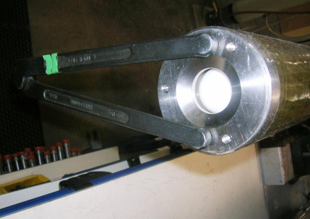
16 Figure 4-5 Using a ½ wrench, loosen the lock nut on the upper valve. (The ½ wrench will need to be modified to access, loosen, and tighten the lock nut) Figure


17 Using a 5/16 wrench, adjust the gap setting between the magplate and the magnet to the thickness of a sheet of paper. Figure 4-7 Figure
18 After setting the upper gap, use both wrenches to lock the valve in place. Hold the valve in place with the 5/16 wrench while tightening the lock nut with the ½ wrench. If you turn the lock nut by itself, it will turn the valve out of spec also. This completes the upper gap setting. Figure

19 Verify and Adjust the Lower Gap Setting If an adjustment to the lower valve is needed, loosen the lock nut to the lower valve using a ¾ and ½ wrenches (Figure 4-10). Turn the lock nut out a few turns to keep it out of the way. Figure 4-10 With the pump held vertically and the control rod and rocker arm in the down position, check the current gap between the lower magplate and the lower magnet. If closed or too far open (such as 1/8 ), use the ½ wrench and pre-set the gap to the thickness of a credit card before proceeding with the gap adjustment (Figure 4-11). 17
, with the control rod up, raise the float until the spring(s) just touches the bottom of the ballast (Figure 4-12).")
20 Figure 4-11 With the pump held vertically, raise the float to force the control rod to the up position (upper magplate being held by the upper magnet, Figure 4-5), with the control rod up, raise the float until the spring(s) just touches the bottom of the ballast (Figure 4-12). 18

21 Figure 4-12 Next, raise the float a little more, slightly compressing the spring ¼ of its length (3/4 if two springs installed). 36 pumps come with one spring assembly above the float that is approximately 4 long, end to end, when new. Compress single spring units ¼. 48 and 60 pumps are built with two springs above the float (approximately 8 in length, end to end, when new). Compress double spring units 3/4. Place a mark on the center pipe where the top of the float rests with this ¼ of compression (Figure 4-13), then let the float down, bringing the control rod down with it. 19
.")
22 Figure 4-13 Make a second mark on the center pipe ¼ above the first mark to indicate the approximate point you want the rocker arm to shift up when the float rises (Figure 4-14). 20

23 Figure 4-14 Lower the float to its resting position, allowing the control rod to be brought back down (Figure 4-15). 21

24 Figure 4-15 Raise the float up until the upper spring(s) just touches the bottom of the ballast, then continue to slowly raise the float, increasing the compression on the spring(s) against the ballast. Watch the center pipe and note where the top of the float is when the control rod shifts up. The shift should occur when the top of the float is approximately at the upper of the two marks you made. The shift of the rocker arm should also be a smooth and somewhat quick movement. If the rocker arm seems to be catching or stalling on something, verify that the rod hasn t been bent and that there is no debris in the hole of the lower magnet or blocking the movement of the rocker arm. If the shift occurs early or late, the lower magnet gap will need to be further adjusted (closed or opened respectively). Use the 1/2 wrench to adjust the valve position in small increments. To decrease the gap, turn the valve counter-clockwise. To increase the gap, turn valve clockwise. Continue to lower and slowly raise the float each time to verify that the shift point happens at the second mark (Figure 4-16). 22
25 Figure 4-16 After setting the lower gap, use both wrenches to lock the valve in place. Hold the valve in place with the 1/2 wrench while tightening the lock nut with the 3/4 wrench. If you turn the lock nut by itself, it will turn the valve out of spec also. The gaps indicated are approximations for a starting point. Minor adjustments during operation may have to be made for the reclaimer to shift properly. 23
26 Section 5: System Troubleshooting Problem: Pump does not discharge fluid to the surface. Solution: Ensure the air pressure is adequate for the pump depth. (See the specifications section, minimum operating pressure example:.43 psi per ft. of static head pressure plus calculated head pressure loss of the piping/tubing). The bottom fluid intake screen is blocked Clear the screen of all debris. The upper fluid intake screen is blocked Clear the screen of all debris. The air exhaust vent hose is kinked or blocked Clear the vent hose of all obstruction, replace if kinked. The Air In or Discharge hoses are kinked or cut Inspect and replace damaged hoses. The lower gap is so close that the float cannot shift the rocker arm upward off the magnet refer to Section 4 for rocker arm adjustment. A regular cleaning may be needed, especially in low activation pumps. Problem: Too much air being injected into the discharged fluid. Solution: Lower magplate gap is too narrow. Increase gap in very small increments. Air pressure set too high for depth. Problem: Fluid shooting out of the vent tube. Solution: Even though some burping is normal, the lower gap may be too wide. Decrease gap in very small increments. When the pump housing is off, care must be taken to not bend the control rod (running the length of the pump) by gripping it with your hand, or allowing the rocker arm assembly to be bent should the pump fall against a hard surface. If the pump continues to not work properly, contact your technical sales representative for assistance. 24
27 Section 6: System Specifications CONSTRUCTION MATERIALS HOUSING MATERIAL CONFIGURATION 36" GEOTECH 3.5 AUTO-RECLAIMER STAINLESS STEEL, PTFE, VITON, HIGH DENSITY POLYETHYLENE, URETHANE FILAMENT WOUND FIBERGLASS REINFORCED EPOXY PIPE/STAINLESS STEEL. 36" DUAL (TOP/BOTTOM) LOADING FIXED INTAKE 36" BOTTOM LOADING FIXED INTAKE PUMP TYPE CONTROLLERLESS CONTROLLERLESS POSITIVE AIR DISPLACEMENT POSITIVE AIR DISPLACEMENT OUTSIDE DIAMETER 3.50 in. (8.89 cm.) 3.50 in. (8.89 cm.) LENGTH in. (113.0 cm.) in. (113.0 cm.) WEIGHT 15.9 lbs. (7.2 kg.) 15.9 lbs. (7.2 kg.) MAX RATED DEPTH 500 ft. (152.4 m.) 500 ft. (152.4 m.) MIN. WELL ID 4.0 in. (10.2 cm.) 4.0 in. (10.2 cm.) OPERATING PRESSURE RANGE psi. ( bar) MIN. OPERATING PRESSURE 1 psi. (.07 bar) above static head AIR CONSUMPTION < ' depth of pump MIN. LIQUID DENSITY.7 SpG (gr/cc) VOLUME/CYCLE.45 gal. (1.70 liters) MAXIMUM FLOW RATE gpm. ( ft gpm. ( ft. 100 psi. 100 psi. MINIMUM ACTIVATION LEVEL 33.0 in. (83.8 cm.) 33.0 in. (83.8 cm.) FITTINGS STAINLESS STEEL (BARB TYPE) HOSE SIZES FLUID DISCHARGE 3/4 x 3/4 MPT AIR SUPPLY 3/8 x 3/8 MPT AIR EXHAUST 1/2 x 3/8 MPT TEMPERATURE SPECIFICATIONS 220 F TOP TEMPERATURE FOR HDPE 25
28 26
29 CONSTRUCTION MATERIALS HOUSING MATERIAL CONFIGURATION 48" GEOTECH 3.5 AUTO-RECLAIMER STAINLESS STEEL, PTFE, VITON, HIGH DENSITY POLYETHYLENE, URETHANE FILAMENT WOUND FIBERGLASS REINFORCED EPOXY PIPE/STAINLESS STEEL. 48" DUAL (TOP/BOTTOM) LOADING FIXED INTAKE 48" BOTTOM LOADING FIXED INTAKE PUMP TYPE OUTSIDE DIAMETER LENGTH WEIGHT CONTROLLERLESS POSITIVE AIR DISPLACEMENT 3.50 in. (8.89 cm.) 56.5 in. (143.5 cm.) 18.0 lbs. (8.2 kg.) CONTROLLERLESS POSITIVE AIR DISPLACEMENT 3.50 in. (8.89 cm.) 56.5 in. (143.5 cm.) 18.0 lbs. (8.2 kg.) MAX RATED DEPTH 500 ft. (152.4 m.) 500 ft. (152.4 m.) MIN. WELL ID 4.0 in. (10.2 cm.) 4.0 in. (10.2 cm.) OPERATING PRESSURE RANGE MIN. OPERATING PRESSURE AIR CONSUMPTION MIN. LIQUID DENSITY VOLUME/CYCLE MAXIMUM FLOW RATE MINIMUM ACTIVATION LEVEL FITTINGS HOSE SIZES FLUID DISCHARGE AIR SUPPLY AIR EXHAUST TEMPERATURE SPECIFICATIONS psi. ( bar) 1 psi. (.07 bar) above static head < ' depth of pump.7 SpG (gr/cc).75 gal. (2.84 liters) 14.5 gpm. ( ft gpm. ( ft. 100 psi. 100 psi in. (114.0 cm.) 45.0 in. (114.0 cm.) STAINLESS STEEL (BARB TYPE) 3/4 x 3/4 MPT 3/8 x 3/8 MPT 1/2 x 3/8 MPT 220 F TOP TEMPERATURE FOR HDPE 27
30 28
31 29
32 CONSTRUCTION MATERIALS HOUSING MATERIAL CONFIGURATION 60" GEOTECH 3.5 AUTO-RECLAIMER STAINLESS STEEL, PTFE, VITON, HIGH DENSITY POLYETHYLENE, URETHANE FILAMENT WOUND FIBERGLASS REINFORCED EPOXY PIPE/STAINLESS STEEL. 60" DUAL (TOP/BOTTOM) LOADING FIXED INTAKE 60" BOTTOM LOADING FIXED INTAKE PUMP TYPE CONTROLLERLESS CONTROLLERLESS POSITIVE AIR DISPLACEMENT POSITIVE AIR DISPLACEMENT OUTSIDE DIAMETER 3.50 in. (8.89 cm.) 3.50 in. (8.89 cm.) LENGTH 68.5 in. (174.0 cm.) 68.5 in. (113.0 cm.) WEIGHT 20.4 lbs. (9.3 kg.) 20.4 lbs. (7.2 kg.) MAX RATED DEPTH 500 ft. (152.4 m.) 500 ft. (152.4 m.) MIN. WELL ID 4.0 in. (10.2 cm.) 4.0 in. (10.2 cm.) OPERATING PRESSURE RANGE psi. ( bar) MIN. OPERATING PRESSURE 1 psi. (.07 bar) above static head AIR CONSUMPTION < ' depth of pump MIN. LIQUID DENSITY.7 SpG (gr/cc) VOLUME/CYCLE 1.05 gal. (3.97 liters) MAXIMUM FLOW RATE gpm. ( ft gpm. ( ft. 100 psi. 100 psi. MINIMUM ACTIVATION LEVEL 57.0 in. (145.0 cm.) 57.0 in. (145.0 cm.) FITTINGS STAINLESS STEEL (BARB TYPE) HOSE SIZES FLUID DISCHARGE 3/4 x 3/4 MPT AIR SUPPLY 3/8 x 3/8 MPT AIR EXHAUST 1/2 x 3/8 MPT TEMPERATURE SPECIFICATIONS 220 F TOP TEMPERATURE FOR HDPE 30
33 31
34 32
35 Section 7: System Schematics Figure Auto-Reclaimer models and dimensions 33
36 Figure Auto-Reclaimer models and dimensions 34
37 Figure Auto-Reclaimer models and dimensions 35
38 Section 8: Replacement Parts List Parts List Parts Description Screen, Intake, PVC, 3.5 Auto (Fluid-in) Bushing, SS4, Intake, 3.5 (Fluid-in) Ball, PTFE, 7/8 (Fluid-in) Hosebarb, SS6, ¾ X ¾ MPT (Discharge) PPP Bushing, SS4, 1 x.75 (Discharge) Bushing, SS4, Orbital, Disch 3.5 (Discharge) Ball, SS, 7/8 (Discharge) Body, SS4, Discharge, 3.5 Auto Hosebarb, SS6, 1/2 X 3/8 MPT (Vent) Hosebarb, SS6, 3/8 X 3/8 MPT (Air-in) Bottom Inlet, SS, 3.5 (Bottom Fill) Cap, Bottom Inlet, 3.5 (Bottom Fill) Ball, TFE, Lower Valve, SS, 3.5 Auto Upper Valve, SS, 3.5 Auto Screw, SS8, 1/4-20 X 3/8, SHCS Spring Guide, DEL, Female, 3.5 Auto Spring, SS6, Upper, Cmprsn, 3.5 Auto Spring, SS6, Lower, Cmprsn, 3.5 Auto Rod, Control, H900, 3.5 Auto Rod, Control, H900, 3.5 Auto Rod, Control, H900, 3.5 Auto Assy, Float, 3.5 Autoreclaimer O-ring, Viton, #336, Shore75A (Housing) O-ring, Viton, #336, Shore75A (Housing) Screen, Inlet, SS, 3.5, Flat Screen, Inlet, SS, 3.5 x Screen, Inlet, SS, 3.5 x Pipe, Center, SS4, ¾ X 36, 3.5AR Pipe, Center, SS4, ¾ X 48, 3.5AR Pipe, Center, SS4, ¾ X 60, 3.5AR Housing, 3.5 AR/Reclaimer, Housing, 3.5 AR/Reclaimer, Housing, 3.5 Autoreclaimer, 60 (Autoreclaimer housings are also available in stainless steel) Pneumatic Counter, 3.5 Autoreclaimer Manual, Autoreclaimer, 3.5 Do not see your part? Then please contact Geotech Sales for more information on available parts and accessories. Ask about our extensive line of tubing and hose. 36
39 NOTES 37
40 NOTES 38
41 NOTES 39
42 The Warranty For a period of one (1) year from date of first sale, product is warranted to be free from defects in materials and workmanship. Geotech agrees to repair or replace, at Geotech s option, the portion proving defective, or at our option to refund the purchase price thereof. Geotech will have no warranty obligation if the product is subjected to abnormal operating conditions, accident, abuse, misuse, unauthorized modification, alteration, repair, or replacement of wear parts. User assumes all other risk, if any, including the risk of injury, loss, or damage, direct or consequential, arising out of the use, misuse, or inability to use this product. User agrees to use, maintain and install product in accordance with recommendations and instructions. User is responsible for transportation charges connected to the repair or replacement of product under this warranty. Equipment Return Policy A Return Material Authorization number (RMA #) is required prior to return of any equipment to our facilities, please call our 800 number for appropriate location. An RMA # will be issued upon receipt of your request to return equipment, which should include reasons for the return. Your return shipment to us must have this RMA # clearly marked on the outside of the package. Proof of date of purchase is required for processing of all warranty requests. This policy applies to both equipment sales and repair orders. FOR A RETURN MATERIAL AUTHORIZATION, PLEASE CALL OUR SERVICE DEPARTMENT AT Model Number: Serial Number: Date of Purchase: Equipment Decontamination Prior to return, all equipment must be thoroughly cleaned and decontaminated. Please make note on RMA form, the use of equipment, contaminants equipment was exposed to, and decontamination solutions/methods used. Geotech reserves the right to refuse any equipment not properly decontaminated. Geotech may also choose to decontaminate the equipment for a fee, which will be applied to the repair order invoice. 40
43
44 Geotech Environmental Equipment, Inc 2650 East 40th Avenue Denver, Colorado (303) (800) FAX (303) website:
Geotech 1.66 Auto-Reclaimer
 Geotech 1.66 Auto-Reclaimer Installation and Operation Rev 9 8/31/06 Part # 16600165 TABLE OF CONTENTS CHAPTER 1: SYSTEM DESCRIPTION... 3 FUNCTION AND THEORY... 3 SYSTEM COMPONENTS... 4 CHAPTER 2: SYSTEM
Geotech 1.66 Auto-Reclaimer Installation and Operation
 Geotech 1.66 Auto-Reclaimer Installation and Operation Rev 10/19/12 Part # 16600165 TABLE OF CONTENTS CHAPTER 1: SYSTEM DESCRIPTION... 3 FUNCTION AND THEORY... 3 SYSTEM COMPONENTS... 4 CHAPTER 2: SYSTEM
Geotech 1.66 Reclaimer
 Geotech 1.66 Reclaimer Installation and Operation Manual Rev 7/1/18 Part # 66 Table of Contents DOCUMENTATION CONVENTIONS... Section 1: System Description... 3 Section : System Installation... 4 Section
Geotech 3.5 Reclaimer Installation and Operation Manual
 Geotech 3.5 Reclaimer Installation and Operation Manual Rev. 2 6/23/03 Part # 26600112 TABLE OF CONTENTS Chapter 1: System Description...p. 0 Function and Theory...p. 0 System Components...p. 0 Chapter
Geotech 1.66 Reclaimer Installation and Operation Manual
 Geotech 1.66 Reclaimer Installation and Operation Manual Rev. 2 6/23/03 Part # 26600137 TABLE OF CONTENTS Chapter 1: System Description...p. 0 Function and Theory...p. 0 System Components...p. 0 Chapter
Geotech Portable Bladder Pumps Installation and Operation Manual
 Geotech Portable Bladder Pumps Installation and Operation Manual Rev. 1 09/22/04 Part # 11150272 Table of Contents System Description... p. 02 Function and Theory...p. 02 System Components... p. 02 System
Geotech Bladder Pumps Installation and Operation Manuals
 Geotech Bladder Pumps Installation and Operation Manuals Rev 12/17/12 Part # 21150035 TABLE OF CONTENTS CHAPTER 1: SYSTEM DESCRIPTION... 2 FUNCTION AND THEORY... 2 SYSTEM COMPONENTS... 3 Bladder Cartridge
Marschalk Model # 94000
 Marschalk Model # 94000 12-volt DC Portable oil-less Air Compressor Operation Manual 27250006 REV 1 9/13/05 Table of Contents CHAPTER 1: SYSTEM DESCRIPTION... 5 FUNCTION AND THEORY... 5 SYSTEM COMPONENTS...
AR4 4 Auto-Reclaimer. Installation and Operation Manual. Rev 10/9/2017 Part #
 AR4 4 Auto-Reclaimer Installation and Operation Manual Rev 10/9/2017 Part # 16600115 Table of Contents Section 1: System Description... 3 Function and Theory... 3 System Components... 4 Section 2: System
Multi-Probe Sampling System User Guide & Manual
 Multi-Probe Sampling System User Guide & Manual Rev. 06/05/12 Part #22200012 Table of Contents CHAPTER 1: SYSTEM DESCRIPTION... 2 FUNCTION AND THEORY... 3 SYSTEM COMPONENTS... 4 CHAPTER 2: SYSTEM INSTALLATION...
Geotech Bladder Pumps
 Geotech Bladder Pumps Installation and Operation Manual Rev 9/18/2017 Part # 21150035 Table of Contents Section 1: System Description... 2 Function and Theory... 3 System Components... 4 Pump Housing...
Geotech Portable Bladder Pumps
 Geotech Portable Bladder Pumps Installation and Operation Manual Rev 02/17/2016 Part # 11150323 Table of Contents CHAPTER 1: SYSTEM DESCRIPTION... 4 CHAPTER 2: SYSTEM INSTALLATION... 7 CHAPTER 3: SYSTEM
ETL Water Level Meter
 ETL Water Level Meter Installation and Operation Manual Rev 8/31/12 Part # 12050319 Table of Contents Section 1: System Description.... 4 Section 2: System Installation.. 7 Section 3: System Operation..
A C Sipper. Installation and Operation Manual. Rev Part #
 A C Sipper Installation and Operation Manual Rev 1-15-09 Part # 16550181 TABLE OF CONTENTS Chapter 1: System Description. p. 05 Function and Theory..p. 05 Chapter 2: System Installation..p. 06 Chapter
ET Water Level Meter. Installation and Operation Manual. Rev 8/31/12 Part #
 ET Water Level Meter Installation and Operation Manual Rev 8/31/12 Part # 12050062 Table of Contents Section 1: System Description.... 4 Section 2: System Installation.. 7 Section 3: System Operation..
VERTICAL BLADDER TANK
 Balanced Pressure Proportioning System Reliable Foam System Requiring Only Water Power Perfect For Tight Spaces UL Listed, ASME, National Board Registered Bladder-UL162 Approved, High Tensile Pressure
BP Controller 300 PSI
 BP Controller 300 PSI Installation and Operation Manual Rev 01/13/2015 Part # 11150362 Table of Contents DOCUMENTATION CONVENTIONS... 2 SECTION 1: SYSTEM DESCRIPTION... 4 FUNCTION AND THEORY... 4 SYSTEM
Installation and Operating Instructions
 Installation and Operating Instructions Neptune Caisson Pump Section 1 Shipment Inspection........Page 2 Section 2 Pre-Installation Checklist....Page 3 Section 3 Installation..............Page 4 Section
NB/NBR NITROGEN BOOSTER FOR AVIATION SERVICE
 NB/NBR NITROGEN BOOSTER FOR AVIATION SERVICE INSTALLATION, OPERATION & MAINTENANCE MANUAL INTERFACE DEVICES, INC. 230 Depot Road, Milford, CT 06460 Ph: (203) 878-4648, Fx: (203) 882-0885, E-mail: info@interfacedevices.com
CS150 CAP STAPLER OWNER S MANUAL
 Operation Revised 6/2013 www.stingerworld.com CS150 CAP STAPLER OWNER S MANUAL! Maintenance Safety Warranty PLEASE READ! This manual contains important information about product safety. WELCOME TO STINGER
FLUSHMATE III FLUSHMATE FLUSHOMETER - TANK SYSTEM. Owner s Service Manual. 503 Series. 503 Series
 Owner s Service Manual 503 Series FLUSHMATE III FLUSHOMETER - TANK SYSTEM 503 Series FLUSHMATE A Division of Sloan Valve Company 30075 Research Drive New Hudson, MI 48165 800-533-3450 248-446-5300 http://www.flushmate.com
CSA Sample Draw Aspirator Adapter Operator s Manual
 30-0951-CSA Sample Draw Aspirator Adapter Operator s Manual Part Number: 71-0367 Revision: 0 Released: 4/30/15 www.rkiinstruments.com WARNING Read and understand this instruction manual before operating
HORIZONTAL BLADDER TANK
 Balanced Pressure Proportioning System Reliable Foam System Requiring Only Water Power Perfect For Low Ceilings UL Listed, ASME, National Board Registered Bladder-UL162 Approved, High Tensile Pressure
Adjustable. Unloader Valve. O&M Manual. Part #
 Adjustable Unloader Valve O&M Manual Unloader Valve Part #60-020-361 ADVANCED PRESSURE SYSTEMS 701 S. Persimmon St., Suite 85 - Tomball, TX 77375 Toll Free in North America: (877) 290-4277 Phone: (281)
RK-IR Sample Draw Aspirator Adapter Operator s Manual
 30-0951RK-IR Sample Draw Aspirator Adapter Operator s Manual Part Number: 71-0018RK Revision: A Released: 6/2/10 www.rkiinstruments.com Product Warranty RKI Instruments, Inc. warrants gas alarm equipment
Pressure Dump Valve Service Kit for Series 2300 Units
 Instruction Sheet Pressure Dump Valve Service Kit for Series 00 Units. Overview The Nordson pressure dump valve is used to relieve hydraulic pressure instantly in Series 00 applicator tanks when the unit
Pressure Injection Cell Operator s Manual
 Pressure Injection Cell Operator s Manual Operator s Manual Pressure Injection Cell CONGRATULATIONS! Congratulations on your purchase of a Next Advance Pressure Injection Cell. Please read this operator
FloWash. Industrial Filter Cart
 OPERATION AND MAINTENANCE MANUAL FloWash Industrial Filter Cart Read all instructions before installation or operation of equipment. Failure to comply with these instructions could result in bodily injury
AutoPump Catalog. Complete Systems. Featuring the AP4 + Series and the new low - maintenance AP4 Ultra
 AutoPump Catalog The Original Automatic Air-Powered Pumps now including the new low maintenance AP Ultra Top Choice at Remediation and Landfill Sites Around the World Complete Systems Featuring the AP
G7S Hand Pump Owner s Manual
 G7S Hand Pump Owner s Manual Copyright Air Venturi 2018 Version 4-18 Specifications 24.80 inches long closed 43.31 inches long extended 4500 psi/310 bar max pressure Features Integral manometer (pressure
OPERATION MANUAL NTF-60 Plus
 OPERATION MANUAL NTF-60 Plus Nitrogen Tire Filling Valve Stem Caps (Qty=200) Order P/N 436075 RTI Technologies, Inc 10 Innovation Drive York, PA 17402 800-468-2321 www.rtitech.com 035-81264-00 (Rev A)
 CS150 CAP STAPLER OWNER S MANUAL Operation Safety Maintenance Warranty! www.stingerworld.com PLEASE READ! This manual contains important information about product safety. REV 06/15 WELCOME TO STINGER Congratula*ons
WARNING: READ THE GENERAL INFORMATION MANUAL INCLUDED FOR OPERATING AND SAFETY PRECAUTIONS AND OTHER IMPORTANT INFORMATION.
 GSR500 Ram Assembly General Description The GSR500 single post lift / ram uses a 3-1/4 air powered cylinder, which is welded to a heavy gauge base. It is normally used to raise and lower a fluid handling
DBML-60/80 Squeeze Tool
 DBML-60/80 Squeeze Tool OPERATORS MANUAL Description The Mustang Model DBML-60/80 Hydraulic squeeze tool has been manufactured since 1995. A Mustang 3 3/4 bore doubleacting cylinder producing 41,000 lbs
Installation, Operation, and Maintenance Manual
 Installation, Operation, and Maintenance Manual Welker The information in this manual has been carefully checked for accuracy and is intended to be used as a guide for the installation, operation, and
accidents which arise due to non-observance of these instructions and the safety information herein. SPECIFICATIONS
 18 GAUGE 2 INCH BRAD NAILER Model: 7555 CALIFORNIA PROPOSITION 65 WARNING: You can create dust when you cut, sand, drill or grind materials such as wood, paint, metal, concrete, cement, or other masonry.
DIAPHRAGM PUMP MODEL PDM 1-175
 INSTRUCTION MANUAL DIAPHRAGM PUMP MODEL PDM 1-175 Manual : 0704 573.034.112 Date : 18/04/07 - Supersede : 17/06/02 - Modif. : + ATEX KREMLIN REXSON - 150, avenue de Stalingrad - 93245 STAINS Cedex - FRANCE
accidents which arise due to non-observance of these instructions and the safety information herein. SPECIFICATIONS
 18 GAUGE 1-1/4 INCH BRAD NAILER Model: 7611 CALIFORNIA PROPOSITION 65 WARNING: You can create dust when you cut, sand, drill or grind materials such as wood, paint, metal, concrete, cement, or other masonry.
Sample Pro Portable MicroPurge Pump. User's Guide P/N REV The World Leader in Air Powered Pumps
 Portable MicroPurge R PATENT PENDING Sample Pro Portable MicroPurge Pump User's Guide P/N 98 REV. -24-03 The World Leader in Air Powered For Remediation, Landfills and Ground Water Sampling Ground water
Rejuvenation Instructions
 Rejuvenation Instructions #401 Air Systems UPR This NRI covers the following: Understanding the applications and operation of flow meters. Understand the application and operation of test pressure gauges.
User Instruction Manual
 User Instruction Manual 4500 psi Air Compressor Ver 2, 1.18 Contents Parts Included...3 Assembly Instructions...3-5 Operation Instructions...6-7 Oil Change Intervals...8 Air Filter Replacement...9 Setting
INDUSTRIAL VALVES MODELS: C62-A; C62-D. INSTRUCTION MANUAL Installation Operation Parts Service DIAPHRAGM BYPASS PRESSURE REGULATING VALVES
 INSTRUCTION MANUAL Installation Operation Parts Service IMPORTANT Record your Regulator model number and serial number here for easy reference: Model No. Serial No. Date of Purchase When ordering parts
BS Series Basket Strainer
 BS Series Basket Strainer Operating, Installation, & Maintenance Manual Corrosion Resistant Fluid and Air Handling Systems. Dated 04-26-12 PRESSURE DROP SIMTECH strainers are engineered to offer the lowest
ATD LB PRESSURE BLASTER INSTRUCTION MANUAL
 ATD-8402 90LB PRESSURE BLASTER INSTRUCTION MANUAL SAVE THESE INSTRUCTIONS SAFETY INSTRUCTIONS FOR SANDBLASTER 1. Before opening the tank release the air pressure on the sand tank. To do this, turn off
Pump On Demand. Skimmer System
 Pump On Demand Skimmer System POD (Pump on Demand) Skimmer System Application Out-of-the-box LNAPL recovery in 2-inch and larger-diameter wells. The POD Skimmer model TR-610 recovers light-end hydrocarbons
PANACEA P200 STAINLESS STEEL USER MANUAL
 Basic Features Stainless Steel body with 1.75 outside diameter. Will fit into wells down to 2 (schedule 80). Has an internal chamber volume of 200mL. Maximum depth below ground surface of 3000ft. Other
OPERATING INSTRUCTIONS MANUAL FOR QACV PNEUMATIC DOSING PUMP
 This operating instructions contains safety information that if ignored can endanger life or result in serious injury. They are indicated by this icon. Use of this pump with radioactive chemicals is forbidden!
GETZ EQUIPMENT INNOVATORS RECOVERY SYSTEM CLEAN AGENT FE-36 / HALOTRON 1 PART NO. 4G59751 OPERATIONS MANUAL
 GETZ EQUIPMENT INNOVATORS CLEAN AGENT FE-36 / HALOTRON 1 PART NO. 4G59751 OPERATIONS MANUAL GETZ EQUIPMENT INNOVATORS PEKIN, ILLINOIS, U.S.A. PHONE: (888) 747-4389 FAX: (309) 495-0625 Limited Warranty
OPERATION MANUAL NTF-15
 OPERATION MANUAL NTF-15 Nitrogen Tire Filling Valve Stem Caps (Qty=200) Order P/N 436075 RTI Technologies, Inc 10 Innovation Drive York, PA 17402 800-468-2321 www.rtitech.com 035-81235-00 (Rev B) TABLE
APCO ASU-SCAV & ASU-CAV SINGLE BODY COMBINATION AIR VALVES
 APCO ASU-SCAV & ASU-CAV SINGLE BODY COMBINATION AIR VALVES Instruction D12039 December 2015 Instructions These instructions provide installation, operation and maintenance information for the. They are
ACRYLIC FLOW METERS 0-30, 0-70 & LPM
 ACRYLIC FLOW METERS 0-30, 0-70 & 0-120 LPM ASSEMBLY INSTRUCTIONS & INSTRUCTIONS FOR USE R219P86 (0-120LPM) R219P87 (0-70LPM) R219P88 (0-30 LPM) R138P11 Rev. D TABLE OF CONTENTS: 1.0 PRODUCT OVERVIEW...1
453 Series Steam Heated Vaporizing Regulator
 ADI 0453A Certified ISO 9001:2000 453 Series Steam Heated Vaporizing Regulator INSTALLATION AND OPERATION INSTRUCTIONS Before Installing or Operating, Read and Comply with These Instructions Controls Corporation
AWG Fittings LLC. Pressure Relief Valve Up to 250 PSI. Product Number Read this instruction manual before use.
 AWG Fittings LLC Pressure Relief Valve Up to 250 PSI Product Number 30004033 Read this instruction manual before use. Using this device without t understanding di this products operation and care may lead
VACUUM REGULATORS CONTENTS
 CAD drawing data catalog is available. ACCESSORIES GENERAL CATALOG AIR TREATMENT, AUXILIARY, VACUUM, AND FLUORORESIN PRODUCTS CONTENTS Small Regulators Features 759 Specifications, Order Codes, Flow Rate
Halsey Taylor Owners Manual STOP!
 Halsey Taylor Owners Manual 4710 Freeze Resistant Floor Mounted Steel Fountain STOP! PLEASE READ THE FOLLOWING INFORMATION. ITALLATION ITRUCTIO FOR THE 4710FR FTN. WITH 97243C SINGLE VALVE CONTROL ASSEMBLY
Submersible Pressure Transducer
 Submersible Pressure Transducer Installation and Operation Manual Rev 5/24/2017 Part # 12050178 Table of Contents Section 1: System Description... 3 Section 2: System Installation... 10 Section 3: System
Section 3- Repair and Calibration Procedures
 Section 3- Repair and Calibration Procedures 1. Refrigerant Removal Procedures 2. Scale/PC Board Recalibration Procedure 3. PC Board Configuration Procedure of AR400 4. Scale Tare Procedure 5. Gauge Calibration
Models: C62/63/64-A/D
 Installation & Service C62-991-24A3 Models: C62/63/64-A/D Diaphragm Bypass Pressure Regulating Valves IMPORTANT Record your pump model number and serial number here for easy reference: Model No. Serial
RASP RX3 Feed UnitTM SPONGE-JET USER MANUAL. Sponge-Jet, Inc. (USA) 14 Patterson Lane Newington, NH
 14 Patterson Lane Newington, NH") SPONGE-JET RASP RX3 Feed UnitTM USER MANUAL Sponge-Jet, Inc. (USA) 14 Patterson Lane +1-603-610-7950 Newington, NH 03801 www.spongejet.com Sponge-Jet RASP RX3 User Manual - REV A / DOC: MKT-014-ENG SPONGE-JET
SPONGE-JET RASP RX3 Feed UnitTM USER MANUAL Sponge-Jet, Inc. (USA) 14 Patterson Lane +1-603-610-7950 Newington, NH 03801 www.spongejet.com Sponge-Jet RASP RX3 User Manual - REV A / DOC: MKT-014-ENG SPONGE-JET
100C Air Compressor Kit
 10010 100C Air Compressor (standard mounting bracket, CE Spec) 10014 100C Air Compressor (no leader hose or check valve, CE Spec) 10016 100C Air Compressor (with Omega Bracket, CE Spec) IMPORTANT: It is
AP-2 AutoPump. AutoPump Controllerless System (for 2-inch wells or larger)
") O P E R A T I O N S M A N U A L AP-2 AutoPump AutoPump Controllerless System (for 2-inch wells or larger) PO Box 3726 6095 Jackson Road Ann Arbor, Michigan 48106-3726 (800) 624-2026 North America Only
O P E R A T I O N S M A N U A L AP-2 AutoPump AutoPump Controllerless System (for 2-inch wells or larger) PO Box 3726 6095 Jackson Road Ann Arbor, Michigan 48106-3726 (800) 624-2026 North America Only
AIR DRIVE ROLL FEED CARTON STAPLER MODEL: H-1031 MANUAL
 AIR DRIVE ROLL FEED CARTON STAPLER MODEL: H-1031 MANUAL WARNING Before operating this stapler familiarize yourself with the safety warnings and instructions in this manual. Keep these instructions with
INSTALLATION, OPERATION AND SERVICE MANUAL ABS AIR BAG LIFT
 INSTALLATION, OPERATION AND SERVICE MANUAL ABS AIR BAG LIFT P.O. Box 1058 1058 West Industrial Avenue Guthrie, OK 73044-1058 405-282-5200 FAX: 405-282-8105 www.autoquip.com Item # 830ABS Version 1.0 07/2001
AIR INLINE METAL SHEAR
 AIR INLINE METAL SHEAR ASSEMBLY and OPERATING INSTRUCTIONS 3491 Mission Oaks Blvd. / Camarillo, CA 93011 Copyright 1997 by Harbor Freight Tools. All rights reserved. No portion of this manual or any artwork
Operation Manual Guillotine Cutter RC-5
 Operation Manual Guillotine Cutter RC-5 Technical Specifications General Safety/Operating Instructions Using the Guillotine Cutter/Crimper Blade Change Instructions Maintenance Instructions This is a detailed
Operating Instructions Models 36200, , 46200, Hydrostatic Test Pumps
 Operating Instructions Models 36200, 362000, 46200, 462000 Hydrostatic Test Pumps 46200 DIMENSIONS: 28 (70cm) L x 24 (60cm) W x 38 (87.5cm) H WEIGHT: PUMP: ENGINE: CONTROL: GAUGE: DISCHARGE HOSE: INTAKE
PROPORTIONING VALVE. Model 150 INSTRUCTION MANUAL. March 2017 IMS Company Stafford Road
 PROPORTIONING VALVE Model 150 INSTRUCTION MANUAL March 2017 IMS Company 10373 Stafford Road Telephone: (440) 543-1615 Fax: (440) 543-1069 Email: sales@imscompany.com 1 Introduction IMS Company reserves
200 PSI COMPRESSORS - MODEL NUMBERS
 200 PSI COMPRESSORS - MODEL NUMBERS 380C AIR COMPRESSOR KIT PART NO. 38033 480C AIR COMPRESSOR KIT PART NO. 48043 380C 480C IMPORTANT: It is essential that you and any other operator of this product read
THE MF-400 SERIES. Operating and Service Manual. Series includes all variants of MF-400/401
 THE MF-400 SERIES Operating and Service Manual Series includes all variants of MF-400/401 Issue A October 2013 1 TABLE OF CONTENTS 1. Description... 3 2. Installation... 3 3. Operation... 4 4. Special
FLUSHMATE FLUSHOMETER - TANK SYSTEM. 501-A Series. Owner s Service Manual. 501-A Series
 Owner s Service Manual 501-A Series FLUSHMATE FLUSHOMETER - TANK SYSTEM 501-A Series A Division of Sloan Valve Company 30075 Research Drive New Hudson, MI 48165 800-533-3450 248-446-5300 http://www.flushmate.com
PCS 340 Core Saturator : 115 Volt : 230 Volt. Instruction Manual
 PCS 340 Core Saturator 127-70: 115 Volt 127-70-1: 230 Volt Instruction Manual Updated 4/30/2015 Ver. 1.2 OFI Testing Equipment, Inc. 11302 Steeplecrest Dr. Houston, Texas 77065 U.S.A. Tele: 832.320.7300
INSTALLATION MANUAL Matheson Tri-Gas Cabinet Enclosures
 INSTALLATION MANUAL Matheson Tri-Gas Cabinet Enclosures MINT-0289-XX TABLE OF CONTENTS Limited Warranty... 3 User Responsibility... 3-4 General Service... 4 Safety Precautions.... 5 Physical Dimensions..
GILMONT ACCUCAL FLOWMETERS
 OPERATING MANUAL GILMONT ACCUCAL FLOWMETERS 28W092 Commercial Ave. Barrington, IL U.S.A. 60010-2392 (847) 381-4888 (847) 381-7053 (Fax) 800-962-7142 www.barnant.com e-mail: barnant@barnant.com A-1299-0766
HPB25 Hydraulic Paving Breaker
 INSTRUCTION MANUAL HPB25 Hydraulic Paving Breaker Read and understand all of the instructions and safety information in this manual before operating or servicing this tool. Register this product at www.greenlee.com
Operation Manual. Carbon Filtration Industrial Drive, Orlinda, TN fax
 Operation Manual Carbon Filtration 615-654-4441 sales@specialtyh2o.com 615-654-4449 fax TABLE OF CONTENTS Section 1 GENERAL 1.1 Warnings and Cautions... 1 1.2 Theory of Operation... 2 1.3 System Illustration...
Float Operated Level Controllers
 CONTENTS Float Operated Level Controllers IM0015 Nov. 2014 PAGE Introduction 1 Scope 1 Description 1 Specification 1 Control Installation 2 INTRODUCTION Side Mount Back Mount Prior to installing, the instructions
INSTRUCTION MANUAL MST AFTERCOOLER SYSTEM MODEL
 INSTRUCTION MANUAL MST AFTERCOOLER SYSTEM MODEL 8059601 To be used with MST Model 8050501 Ambient Air Pump 7/12/05 2 TABLE OF CONTENTS GENERAL INFORMATION... 3 WARNING...4,5 UNPACKING AND AFTERCOOLER ASSEMBLY
SSFU SUPER SPRAYFAST UNIVERSAL ADHESIVE APPLICATOR
 S S F U SSFU SUPER SPRAYFAST UNIVERSAL ADHESIVE APPLICATOR MACHINERY DIVISION OWNER S MANUAL UNIT INSTRUCTIONS Please follow all SSFU Safety Instructions. Contact your Duro Dyne Tech Service if you have
INSTALLATION. and INSTRUCTION MANUAL. for QUALITY AIR BREATHING SYSTEMS. Model 50-P-Mini Portable Systems Outfitted with ABM-725 Monitor
 INSTALLATION and INSTRUCTION MANUAL for QUALITY AIR BREATHING SYSTEMS Model 50-P-Mini Portable Systems Outfitted with ABM-725 Monitor M A R T E C H S E R V I C E S C O M P A N Y P.O. Box 7079 OFFICE: (507)
 RT3 CAP NAILER OWNER S MANUAL Operation Safety Maintenance Warranty! www.stingerworld.com PLEASE READ! This manual contains important information about product safety. REV 09/14 WELCOME TO STINGER Congratulations
Owners Manual MAX-10/45 Upper Receiver. Rev. A. NFA Warning. LAGE Manufacturing, L.L.C. 916 E. Baseline Rd. STE #113 Mesa, AZ 85204
 Owners Manual MAX-10/45 Upper Receiver NFA Warning LAGE Manufacturing, L.L.C. 916 E. Baseline Rd. STE #113 Mesa, AZ 85204 CM109mk2-300 Rev. A This upper receiver is designed to be used with the M-10/45
Pressure Dump Valve Service Kit for Series 3000 Units
 Instruction Sheet Pressure Dump Valve Service Kit for Series 000 Units. Overview The Nordson pressure dump valve is used to relieve hydraulic pressure instantly in Series 00, 400, 500, and 700 applicator
AIR COMPRESSOR. Failure to follow all instructions as listed below may result in electrical shock, fire, and/or serious personal injury.
 2 GALLON AIR COMPRESSOR Model: 7517 DO NOT RETURN TO STORE. Please CALL 800-348-5004 for parts and service. CALIFORNIA PROPOSITION 65 WARNING: You can create dust when you cut, sand, drill or grind materials
Index Table. Model 794. Installation, Operating and Maintenance Instructions
 CLOCKWISE MANUAL MAKING INTO CCW TABLE Index Table Model 794 Installation, Operating and Maintenance Instructions Black & Webster Products Division 545 Hupp Ave. P.O. Box 831, Jackson, Michigan 49204 2009
5 Gallon Pressure Pot with HVLP Spray Gun and Hose
 California Air Tools 5 Gallon Pressure Pot with HVLP Spray Gun and Hose Model No. 365 Technical Data Type of feed.pressure Maximum pressure in the tank... 0,413Mpa (60PSI) Working pressure in the tank.0,
Inflatable Packer Single & Double. Single & Double Packer Dimension. Wireline Packer. Water Testing Packer (WTP) Packer
 Packer") Inflatable Packer Single & Double Single & Double Packer Dimension Wireline Packer Water Testing Packer (WTP) Packer Packer Working Pressure & Depth Chart Packer Water Hand Pump Packer Air Driven Pump
Inflatable Packer Single & Double Single & Double Packer Dimension Wireline Packer Water Testing Packer (WTP) Packer Packer Working Pressure & Depth Chart Packer Water Hand Pump Packer Air Driven Pump
600 / 600FC OWNER'S MANUAL
 PROGRESSION 600 / 600FC OWNER'S MANUAL Issue 2 / Version E - Dec. 10, 1997 Copyright 1997 GAMMA Sports - All Rights Reserved PROGRESSION 600 / 600FC OWNER'S MANUAL TABLE OF CONTENTS PAGE 1... WARRANTY
THE BP-301 SERIES. Operating and Service Manual. Series includes all variants of BP-301 (LF 0.1Cv / MF 0.5Cv)
") THE BP-301 SERIES Operating and Service Manual Series includes all variants of BP-301 (LF 0.1Cv / MF 0.5Cv) Issue B October 2015 1 TABLE OF CONTENTS 1. Description... 3 2. Installation... 3 3. Operation...
THE BP-301 SERIES Operating and Service Manual Series includes all variants of BP-301 (LF 0.1Cv / MF 0.5Cv) Issue B October 2015 1 TABLE OF CONTENTS 1. Description... 3 2. Installation... 3 3. Operation...
isup MANUAL THANK YOU FOR PURCHASING A KAHUNA isup, WE HOPE YOU HAVE MANY YEARS OF PADDLING ENJOYMENT.
 i isup MANUAL THANK YOU FOR PURCHASING A KAHUNA isup, WE HOPE YOU HAVE MANY YEARS OF PADDLING ENJOYMENT. THIS MANUAL IS A GENERAL GUIDELINE FOR SET-UP, CARE AND PROPER USE. PLEASE REFER TO OUR WEBSITE
TECHNICAL DATA. Q = C v P S
 January 6, 2012 Preaction 347a 1. Description Viking supervised Double-Interlocked Electric/Pneumatic Release Preaction Systems utilize the Viking G-6000P Valve. The small profile, lightweight, pilot operated
Instruction Manual. PE-25/32/37 Tapping Machines. POLYTAPP Valves
 Instruction Manual PE-25/32/37 Tapping Machines & POLYTAPP Valves Nov 2016, Revision 2 Document Number 3000111 2 M.T. Deason Company, Inc. PO Box 101807 Birmingham, AL 35210 Phone: 205 956 2266 Fax: 205
DFB FLOW METERS (DESIGNED FOR BLENDERS, DUAL TAPER)
") DFB FLOW METERS (DESIGNED FOR BLENDERS, DUAL TAPER) 0-3, 0-15, 0-30 & 0-70 LPM ASSEMBLY INSTRUCTIONS & INSTRUCTIONS FOR USE R219P87-400 (0-70 LPM) R219P88-400 (0-30 LPM) R219P79-400 (0-15 LPM) R219P99-400
DFB FLOW METERS (DESIGNED FOR BLENDERS, DUAL TAPER) 0-3, 0-15, 0-30 & 0-70 LPM ASSEMBLY INSTRUCTIONS & INSTRUCTIONS FOR USE R219P87-400 (0-70 LPM) R219P88-400 (0-30 LPM) R219P79-400 (0-15 LPM) R219P99-400
Instruction Manual. PE Pipe Squeeze-off Tool Model TR650
 PE Pipe Squeeze-off Tool Model TR650 Instruction Manual For your personal safety READ and UNDERSTAND instructions before using tools. SAVE these instructions for future reference. SPECIFICATIONS Table
TECHNICAL DATA. Page 1 of 12
 Page 1 of 12 1. DESCRIPTION The Viking Regulating Valve is a direct-acting, single-seated, spring-loaded diaphragm valve. When installed as a pilot regulating valve on a Viking Model H or J Flow Control
IMPORTANT SAFETY INSTRUCTIONS
 IMPORTANT SAFETY INSTRUCTIONS CAUTION - To reduce risk of electrical shock: - Do not disassemble. Do not attempt repairs or modifications. Refer to qualified service agencies for all service and repairs.
TECHNICAL DATA. Q = C v P S
 January 6, 2012 Preaction 331a 1. Description Viking supervised Double-Interlocked Electric/Pneumatic Release Preaction Systems utilize the Viking G-3000P Valve. The small profile, lightweight, pilot-operated
Operating Instructions Models and Hydrostatic Test Pumps
 Operating Instructions Models 33100 and 33101 Hydrostatic Test Pumps 33100 DIMENSIONS: WEIGHT: PUMP: MOTOR: CONTROL: GAUGE: DISCHARGE HOSE: 16 (40cm) L x 22 (55cm) W x 18 (45cm) H 87 lbs., 39.5 kg Triplex
Hydraulic Punch Drivers
 SERVICE MANUAL 7804SB / 7806SB Quick Draw 7704SB / 7706SB Quick Draw Flex Quick Draw Hydraulic Punch Drivers Serial Codes AHJ and YZ Read and understand all of the instructions and safety information in
420C AIR COMPRESSOR KIT PART NO C AIR COMPRESSOR KIT PART NO
 420C AIR COMPRESSOR KIT PART NO. 42042 460C AIR COMPRESSOR KIT PART NO. 46043 420C 460C IMPORTANT: It is essential that you and any other operator of this product read and understand the contents of this
Model B-1 Pipe Line Strainer 3, 4, 6 & 8 Inch (DN80, DN100, DN150 & DN200) 175 psi (12,1 bar) General Description. Technical Data
 175 psi (12,1 bar) General Description. Technical Data") Technical Services: Tel: (800) 381-312 / Fax: (800) 71-5500 Customer Service/Sales: Tel: (215) 362-0700 / (800) 523-6512 Fax: (215) 362-5385 Model B-1 Pipe Line Strainer 3,, 6 & 8 Inch (DN80, DN100, DN150
Technical Services: Tel: (800) 381-312 / Fax: (800) 71-5500 Customer Service/Sales: Tel: (215) 362-0700 / (800) 523-6512 Fax: (215) 362-5385 Model B-1 Pipe Line Strainer 3,, 6 & 8 Inch (DN80, DN100, DN150