K220LS Mobile Directional Control Valve
|
|
|
- Kristian Greer
- 5 years ago
- Views:
Transcription

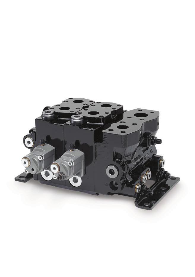
1 Proportional, Load Sensing, Pre-compensated
2 Catalogue layout This catalogue has been designed to give a brief overview of valves, and to make it easy for you to study and choose from the different options available, so that we may customize your valve in accordance with your wishes. In addition to general information and basic technical data, the catalogue therefore contains descriptions of the options available for various so-called function areas of the valve. Each function area is given as a subheading, followed by a brief description. When options are available for a function area, the subheading is followed by an Item number in brackets, e.g. Pressure relief valve [16]. This is followed by a series of coded options, e.g. PA1, Y1, together with a brief description of what each code represents. Alternatively, one or more pressure, flow or voltage options are given. Please note that, unless stated otherwise, all sections and views of the valves have been drawn as seen from the inlet section. How to order your valve The directional control valve can be easily specified using Parker computer programme. This means the customer can optimise his valve specification to give the best performance for his application and specific hydraulic system. Once the demands placed on each individual function have been specified the computer will select the valve design required to give optimum performance. The computer also produces complete documentation for your valve, in the form of a detailed specification and hydraulic circuit diagram. The computer also generates a unique identification number for each valve type and customer. The number is then stamped into the I.D. plate of each valve. The specification of your valve is then recorded by Parker, so that exact identification of the product can be made at any time in the future to facilitate repeat ordering or servicing. Early consultation with Parker saves time and money Our experienced engineers have in-depth knowledge of the different types of hydraulic system and the ways in which they work. They are at your disposal to offer qualified advice on the best system for the desired combination of functions, control characteristics and economic demands. By consulting Parker early in the project planning stage, you are assured of a comprehensive hydraulic system that gives your machine the best possible operating and control characteristics. Conversion factors 1 kg = lb 1 N = lbf 1 bar = psi 1 l = UK gallon 1 l = US gallon 1 cm 3 = in 3 1 m = feet 1 mm = in 9/5 C + 32 = F 2 Parker Hannifin
3 Contents Table of contents Page General Information...4 Technical Data...5 Inlet Section...7 Spool Section...8 Connections [04] and [47]...8 Mid-inlet section [90-99]...8 Pressure compensator and/or load-hold check valve [66]...9 Feed reducer valve [75]...9 Dimensional Drawings...10 [00] refers to item numbers in the customer specification. 3 Parker Hannifin
4 General Information The is a development of our K170LS directional valve and this leaflet serves only as a complement to the K170LS product catalogue. The numeric codes [00] used in the illustrations and with the sub-headings for specifiable valve functions are therefore the same as those used in the K170LS catalogue and the product specification program SYBER. Compact system construction Many system functions can be integrated into the, reducing the number of components simplifying the installation. By means of an adapter plate, the can be combined with the smaller L90LS directional valve to serve functions requiring lower flow. This arrangement is very compact and economical. Freedom in machine design The is supplied with spool actuators for either hydraulic or electrohydraulic proportional remote control. This gives great flexibility in terms of component location and the running of pipework, hoses and electric cables. Economy The can be rebuilt - to increase or reduce the number of spools - at any time to suit the needs of the customer. Moreover, the various valve functions can be adapted to suit the application in question, thus keeping energy consumption to a minimum. Control characteristics Thanks to unique function-adapted valve spools, the gives outstanding control characteristics in both the lifting and lowering movements. Design Sectional construction - The is sectionally built and can be supplied in combinations of 1 to 7 spool sections. It is designed for a system pressure of 350 bar and can be used with pump flows of up to 280 l/min (2 x 280 l/min with mid-inlet section). The nominal maximum flow per spool section is 200 l/min with compensator. Pressure compensation - An individual pressure compensator in each spool section gives excellent control characteristics. Feed reducer(s) - Common or individual feed reducers can be adjusted between 30 and 330 bar, limiting the pressure in the respective service ports. Pressure reduction is achieved through the pressure compensator, which shuts off the oil flow. Force feedback - Force-regulating control characteristics give not only efficient acceleration of swing functions but also more gentle transition in speed changes. 4 Parker Hannifin
5 Technical Data Take-off of uncopied load pressure, PL Gauge port for pump pressure, PX Pump connection, P1 [26] Service port B Tank connection, TM2 [92] Tank connection, TM1 UTake-off of copied loadpressure for pump regulator, LS Take-off of pilotpressure for external use, PS Pump connection, P2 [32] Separate tank connection for pilot tank, TP [40] Tank connection, T1 [25] Mid-inlet section, M1 [90] Pump connection, PM Tank connection, T2 [24] Connection for pilot control of counter pressure, MP [24] Connection for hydraulic remote control, PC (A- and B-port) Service port A Pressure Pump inlet max. 350 bar (5075 psi) 1) Service ports max. 350 bar (5075 psi) 1) Pump regulator p min. 18 bar (260 psi) 2) Compensator K3 p min. 30 bar (435 psi) 2) Return line pressure (static) max. 15 bar (215 psi) 1) Stated pressures are maximal absolute shock pressures at 10 bar (145 psi) tank pressure 2) Pressure drop from pump to valve max. 3 bar (45 psi) Temperature Oil temperature, working range +20 C to +90 C* (68 to 194 F) Filtration Filtration must be arranged so that Target Contamination Class 20/18/14 according to ISO 4406 is not exceeded. For the pilot circuit, Target Contamination Class 18/16/13 according to ISO 4406 must not be exceeded. Hydraulic fluids Best performance is obtained using mineral-base oil of high quality and cleanness in the hydraulic system. Hydraulic fluids of type HLP (DIN 51524), oil for automatic gearboxes Type A and engine oil type API CD can be used. Viscosity, working range mm 2 /s** Technical information in this catalogue is applicable at an oil viscosity of 30 mm 2 /s and temperature of 50 C (122 F) using nitrile rubber seals. * Product operating limits are broadly within the above range, but satisfactory operation within the specification may not be accomplished. Leakage and response will be affected when used at temperature extremes and it is up to the user to determine acceptability at these levels. ** Performance efficiency will be reduced if outside the ideal values. These extreme conditions must be evaluated by the user to establish suitability of the products performance. 5 Parker Hannifin
6 Technical Data Weight The weights given below are approximate, since they vary somewhat depending on valve configuration. Inlet section 11.4 kg 25.1 lb Spool section with PC spool actuator 13.1 kg 28.9 lb Spool section with EC spool actuator 14.5 kg 32.0 lb End section 4.1 kg 9.0 lb Combi-inlet 11.5 kg 25.4 lb Connections P1, PM, T1, TM and the service ports A and B are fitted with so-called flange plane connections according to ISO /2. Fixing screws for the flanges are available in two versions, UNC and metric. Other connections are available in two versions: G-version (BSP pipe thread) for flat seal (type Tredo) as per ISO 228/1 and UNF-version for O-ring seal as per ISO In section Connection G-version. UNF-version P1 inlet section Flange SAE 1 High pressure ISO ) T1 inlet section Flange SAE 1 1/4 Std pressure ISO ) T2 inlet section G 1 1 5/16-12 UN-2B P1 combo-inlet CA/CL Flange SAE 1 High pressure ISO ) T1 combo-inlet CA/CL Flange SAE 1 1/4 Std pressure ISO ) T2 combo-inlet CA/CL G 1 1 5/16-12 UN-2B LS, PL, PX, PS inlet, combo-inlet CA/CL G 1/4 9/16-18 UNF-2B MP inlet section G 1/4 9/16-18 UNF-2B PM mid-inlet section Flange SAE 1 High pressure ISO ) TM mid-inlet section Flange SAE 1 1/4 Std pressure ISO ) TM2 mid-inlet section G 1 1 5/16-12 UN-2B P2 end section G 1 1 5/16-12 UN-2B T3 end section G 1/4 9/16-18 UNF-2B TP end section G 1/4 9/16-18 UNF-2B TP combo-inlet CA/CL G 3/8 3/4-16 UNF-2B LSP end section G 3/8 9/16-18 JIC (37 ) (male) YS combo-inlet CA/CL G1/4 9/16-18 JIC (37 ) (male) A, B spool section Flange SAE 1 Std pressure ISO ) A, B spool section Flange SAE 3/4 High pressure ISO ) PC spool section G 1/4 9/16-18 UNF-2B 1) Screw M12 or 7/16-14 UNC, depth of thread 25 mm 2) Screw M10 or 3/8-16 UNC, depth of thread 20 mm 3) Screw M10 or 7/16-14 UNC, depth of thread 20 mm 6 Parker Hannifin
![Inlet Section Pump connection P1 [26] Tank connection T1 [25] Counter pressure valve Tank connection T2 [24] Pressure relief valve PA1 [16, 17] Copying spool for load signal Pilot filter [14] Load](/docs-images/93/112806624/images/7-0.jpg "signal (not copied) connection PL Gauge port, pump pressure PX Load signal (copied) connection LS Pilot pressure supply for external use PS Inlet section [12-29] The inlet section is equipped with a")
7 Inlet Section Pump connection P1 [26] Tank connection T1 [25] Counter pressure valve Tank connection T2 [24] Pressure relief valve PA1 [16, 17] Copying spool for load signal Pilot filter [14] Load signal (not copied) connection PL Gauge port, pump pressure PX Load signal (copied) connection LS Pilot pressure supply for external use PS Inlet section [12-29] The inlet section is equipped with a pump connection (P1) and two tank connections (T1, T2). It is also equipped with connections for a copied load signal to the pump (LS), an uncopied load signal to a subsequent valve (PL), a gauge point for measuring the pump pressure (PX), a take-off of reduced pump-pressure for external pilot-oil supply (PS) and a connection for transmitting the maximum load signal on to a subsequent valve (PL2). The inlet section also contains a copying spool for copying the load-signal pressure, a reducer valve with a built-in pressure relief valve for reducing the pump pressure to pilot pressure, a strainer to filter the pilot oil and a pressure relief valve that limits the maximum pressure of the valve, a counter pressure valve in T2. The strainer for the pilot oil can be replaced with an external filter. AS Inlet section with flow distribution function for systems with variable pump. The section distributes the pump flow between activated spool sections fitted with compensator type KAS [66], at maximum flow take-off from the pump. With other inlet types, the consumer working the hardest receives no flow, which instead goes to the consumer with the lowest load. The section is equipped with a load pressure limiting valve, PLM [16], and a differential pressure limiting valve (pump pressure-load pressure), PLS [18]. Valves with AS inlet are located closest to the pump in a multi-valve system with the load signal connected to the pump regulator. CA/CL Combo inlet used as mid-inlet when L90 and K220 are assembled together. This works as an adapter plate between valves and replaces inlet sections from both valves. The combination inlet is available with the same functionality as the LS2, AS and AS2 inlets. It can also include pilot pressure supply and the counter pressure function. For more information see the catalogue for L90LS. AS2 Inlet section for following valve in a flow distribution system. The load signal from this valve is connected to the preceding valve. Otherwise, the functionality is as for inlet section AS except that the section only contains a load pressure limiting valve, PLM [16]. IP Inlet plate without functions. Contains only connections for pump, tank and load signal. LS2 Inlet section for systems with variable pump. Equipped with a non-adjustable, direct-acting pressure relief valve, PA1 [16], which protects the pump and inlet side of the valve. The LS2 variant is equipped with a copy function for the load signal. Combo-inlet CA 7 Parker Hannifin
8 Spool Section Spool section with PC spool actuator Common feed reducer MRM or MRC [75] Port relief valve, port B [76B] Port B [47] Port A [47] Port relief valve, port A [76A] Bleeder nipple Spool [69] Limiting of flow, Qset, QsetB [72] PC spool actuator [50] Bleeder nipple Limiting of flow, Qset, QsetA [72] Pilot pressure connection (P - B, A - T) Pilot pressure connection (P - A, B - T) Compensator damping [67] Compensator [66] Spool section [45-89] The is a stackable directional valve and can be supplied in combinations of 1 to 7 spool sections. Each section can be equipped individually to incorporate a large number of different functions. By means of function-adapted spools, spool actuators, pressure relief valves, pressure compensators, etc. the valve can be optimized to suit different applications. PM TM Connections [04] and [47] The section service-port connections are the flange type according to ISO /2. The fixing-screw threads are available in two versions, UNC and M. Other connections on the section are of G type according to ISO 228/1 (for flat seal) or UN type according to ISO (for O-ring seal). Please see page 6 for dimensions. MG MU UU FCS FCH Flanged connection with M threaded fixing screws. Other connections of G type. Flanged connection with M threaded fixing screws. Other connections of UN type. Flanged connection with UNC threaded fixing screws. Other connections of UN type. Spool section with service ports A and B according to ISO /2 Standard Pressure. Spool section with service ports A and B according to ISO /2 High Pressure. Mid-inlet section [90-99] In certain applications, e.g. the feeding of crawler-track motors on an excavator, there is a demand for high flow from two sections at the same time. This can be achieved by means of the mid-inlet section Ml [90], which can be mounted anywhere in the valve. Ideally, however, the high flows should be obtained from the first and last spool sections, and the mid-inlet section should be mounted between the last spool section and the end section. Valves with mid-inlet sections can be fed with a pump flow of 2 x 280 l/min. The mid-inlet section also contains two tank connec- Mid-inlet section with counter pressure valve. tions or, alternatively, one tank connection and a counter pressure valve (the same counter pressure valve that can be used in T2 [24].) There are two mounting plates on the mid-inlet section, one on each side. These should be used if the valve is to be mounted in any way other than with the service ports facing upward. See dimensional drawing on page Parker Hannifin
9 Spool Section Pressure compensator and/or load-hold check valve [66] K1 K2 K3 KN1 KAS N1 X1 Fixed pressure compensator with load-hold check valve. The spool gives nominal flow. Fixed pressure compensator with load-hold check valve. The spool gives 20% more than nominal flow. Fixed pressure compensator with load-hold check valve. The spool gives 55% more than nominal flow. N.B. Pump must deliver a pressure of at least p=30 bar. (30 bar above load signal reported to pump regulator.) Fixed pressure compensator with extra fast load-hold check valve. The spool gives 15% more than nominal flow. Compensator for systems with flow distribution. In sections with KAS compensators, the flow take-off is reduced by the same percentage at maximum flow-takeoff from the pump. With a pressure difference of 20 bar between PX and LS, the flow to the motor ports is about the same as with a compensator of type K3. If the same valve contains sections with compensators of type K1, K2, K3 or KN1, these will be given priority over sections with KAS compensators in terms of flow take-off. This makes it easy to establish priority for a specific function. Load-hold check valve. Prepared for compensator and load-hold check valve. Section equipped with feed reducer valve type MR. Feed reducer valve [75] Any section in the can be equipped with individual feed reduction on service ports A and B. Feed reduction is used for functions in a system which require a lower maximum pressure than the normal working pressure of the system. The reducer valve is adjustable and reduces the feed pressure in the section to a pre-set level. By using a feed reducer valve, the feed pressure can be limited without consuming any more than a pilot flow (<2 l/min). When using the feed reduction function, the section must be equipped with a pressure compensator as the feed reducer is a two-stage valve. Pressure shocks that arise after the feed reducer valve must be limited with the aid of a port relief valve. The pressure setting in the port relief valve [76 A,B] should be as close as possible to that in the feed reducer valve, but at least 10 bar higher. Section equipped with feed reducer valve type MRC. MR MRC MRM Feed reducer for individual setting of maximum pressures in service ports A and B. Pressure settings from 30 to 330 bar. Feed reducer for common setting of maximum pressure in service ports A and B. Pressure settings from 175 to 330 bar. Feed reducer for common setting of maximum pressure in service ports A and B, as well as the service ports in all subsequent sections (seen from the inlet section). Sections located downstream of a section equipped with MRM can be equipped with individual feed reducer valves provided that they are set at lower values. Pressure settings from 175 to 330 bar. Section equipped with feed reducer valve type MRM. 9 Parker Hannifin
10 Dimensional Drawings (8.07) (7.01) (6.42) (inch) (4.09) 104 (T2) (7.13) 181 (5.94) 151 (4.76) 121 (60) (2.36) 96 (3.78) 16 (0.63) 60 max (2.36) 102 (4.15) 48 (1.89) 41 (PL2) (1.61) 40 (YS) (1.57) 38 (1.50) No. of L L sections mm inch (1.85) 47 (LSP) (0.55) 14 (XA) 35 (XB) (1.38) L Mid-inlet section 100 (3.94) 53 (2.09) 72 (2.83) 145 (5.71) 32 Service port B P1 Service port A (3.78) 96 (PL2) 84 (3.31) 66 (2.60) (11.34) (10.00) (4.76) (1.26) 121 TM1 T1 (Ø0.53) Ø13,5 (0.24) PM (10.23) 260 max 245 (9.64) (5.94) (5.28) 134 (5.28) 115 (4.53) (2.36) (2.44) 62 (2.13) 39 (1.54) (0.91) 23 (0.55) 14 (2X) (0.79) (1.73) 6 13 (0.51) 35 (1.38) 53 (2.09) 17 (0.67) 37 (1.45) 61 (XA) (2.40) 64 (2.52) 74 (XB) (2.91) 167(6.57) (3.86) (T3, LSP) (4.37) TM2 Lifting eye Ø15 (0.59) Toward inlet section 10 Parker Hannifin
11 ! WARNING FAILURE OR IMPROPER SELECTION OR IMPROPER USE OF THE PRODUCTS AND/OR SYSTEMS DESCRIBED HEREIN OR RELATED ITEMS CAN CAUSE DEATH, PERSONAL INJURY AND PROPERTY DAMAGE. This document and other information from Parker Hannifin Corporation, its subsidiaries and authorized distributors provide product and/or system options for further investigation by users having technical expertise. It is important that you analyze all aspects of your application, including consequences of any failure, and review the information concerning the product or system in the current product catalogue. Due to the variety of operating conditions and applications for these products or systems, the user, through its own analysis and testing, is solely responsible for making the final selection of the products and systems and assuring that all performance, safety and warning requirements of the application are met. The products described herein, including without limitation, product features, specifications, designs, availability and pricing, are subject to change by Parker Hannifin Corporation and its subsidiaries at any time without notice. Offer of Sale Please contact your Parker representation for a detailed Offer of Sale. 11 Parker Hannifin
12 Parker Worldwide AE UAE, Dubai Tel: parker.me@parker.com AR Argentina, Buenos Aires Tel: AT Austria, Wiener Neustadt Tel: +43 (0) parker.austria@parker.com AT Eastern Europe, Wiener Neustadt Tel: +43 (0) parker.easteurope@parker.com AU Australia, Castle Hill Tel: +61 (0) AZ Azerbaijan, Baku Tel: parker.azerbaijan@parker.com BE/LU Belgium, Nivelles Tel: +32 (0) parker.belgium@parker.com BR Brazil, Cachoeirinha RS Tel: BY Belarus, Minsk Tel: parker.belarus@parker.com CA Canada, Milton, Ontario Tel: CH Switzerland, Etoy Tel: +41 (0) parker.switzerland@parker.com CN China, Shanghai Tel: CZ Czech Republic, Klecany Tel: parker.czechrepublic@parker.com DE Germany, Kaarst Tel: +49 (0) parker.germany@parker.com DK Denmark, Ballerup Tel: parker.denmark@parker.com ES Spain, Madrid Tel: parker.spain@parker.com FI Finland, Vantaa Tel: +358 (0) parker.finland@parker.com FR France, Contamine s/arve Tel: +33 (0) parker.france@parker.com GR Greece, Athens Tel: parker.greece@parker.com HK Hong Kong Tel: HU Hungary, Budapest Tel: parker.hungary@parker.com IE Ireland, Dublin Tel: +353 (0) parker.ireland@parker.com IN India, Mumbai Tel: IT Italy, Corsico (MI) Tel: parker.italy@parker.com JP Japan, Fujisawa Tel: +(81) KR South Korea, Seoul Tel: KZ Kazakhstan, Almaty Tel: parker.easteurope@parker.com LV Latvia, Riga Tel: parker.latvia@parker.com MX Mexico, Apodaca Tel: MY Malaysia, Subang Jaya Tel: NL The Netherlands, Oldenzaal Tel: +31 (0) parker.nl@parker.com NO Norway, Ski Tel: parker.norway@parker.com NZ New Zealand, Mt Wellington Tel: PL Poland, Warsaw Tel: +48 (0) parker.poland@parker.com PT Portugal, Leca da Palmeira Tel: parker.portugal@parker.com RO Romania, Bucharest Tel: parker.romania@parker.com RU Russia, Moscow Tel: parker.russia@parker.com SE Sweden, Spånga Tel: +46 (0) parker.sweden@parker.com SG Singapore Tel: SK Slovakia, Banská Bystrica Tel: parker.slovakia@parker.com SL Slovenia, Novo Mesto Tel: parker.slovenia@parker.com TH Thailand, Bangkok Tel: TR Turkey, Istanbul Tel: parker.turkey@parker.com TW Taiwan, Taipei Tel: UA Ukraine, Kiev Tel parker.ukraine@parker.com UK United Kingdom, Warwick Tel: +44 (0) parker.uk@parker.com US USA, Cleveland (industrial) Tel: US USA, Lincolnshire (mobile) Tel: VE Venezuela, Caracas Tel: ZA South Africa, Kempton Park Tel: +27 (0) parker.southafrica@parker.com European Product Information Centre Free phone: (from AT, BE, CH, CZ, DE, EE, ES, FI, FR, IE, IT, PT, SE, SK, UK) HYGE Ed Parker Hannifin Corporation. All rights reserved. Catalogue HY /UK. POD 10/2007 PC Parker Hannifin Ltd. Tachbrook Park Drive Tachbrook Park, Warwick CV34 6TU United Kingdom Tel.: +44 (0) Fax: +44 (0) Your local authorized Parker distributor
PRS6 Auxiliary Valves
 Pressure Reducing Valves General Subject to alteration without prior notice. The curves and diagrams in this catalogue are typical examples only. While the contents of the catalogue are updated continuously,
K220LS Mobile Directional Control Valve
 Proportional, Load Sensing, Pre-compensated Catalogue layout This catalogue has been designed to give a brief overview of valves, and to make it easy for you to study and choose from the different options
VP04 Remote Control. Pneumatic Proportional Remote Control Valve
 Remote Control Pneumatic Proportional Remote Control Valve Catalogue Information Catalogue layout This catalogue has been designed to give a brief overview of the, and to make it easy for you to study
Transair: Advanced pipe systems For Nitrogen Applications
 Transair: Advanced pipe systems For Nitrogen Applications aerospace climate control electromechanical filtration fluid & gas handling hydraulics pneumatics process control sealing & shielding NITROGEN
Auxiliary Valve PRS6 Pressure Reducing Valve. Catalogue HY /UK June 2003
 Auxiliary Valve Pressure Reducing Valve June 2003 General Subject to alteration without prior notice. The curves and diagrams in this catalogue are typical examples only. While the contents of the catalogue
Remote Control VP04 Pneumatic Proportional Remote Control Valve zrc02. Catalogue HY /UK December, 2004
 Remote Control Pneumatic Proportional Remote Control Valve zrc02 Catalogue HY17-8356/UK December, 2004 Catalogue Information Catalogue layout This catalogue has been designed to give a brief overview of
Directional Control Valves
 aerospace climate control electromechanical filtration fluid & gas handling hydraulics pneumatics process control sealing & shielding Directional Control Valves Series VA13 and VA15 3- and 5-port valves.
HPRV Proportional Relief Valve. Catalog 4190-HPRV
 HPRV Proportional Relief Valve Catalog 419-HPRV Contents Page 3... Introduction Page 4... Seal & Spring Options Page 5... Dimensions Page 6... Materials of Construction Page 7... How to Order 2 Introduction
Directional Control Valves
 aerospace climate control electromechanical filtration fluid & gas handling hydraulics pneumatics process control sealing & shielding Directional Control Valves Series VA13 and VA15 3- and 5-port valves.
M402LS Mobile Directional Control Valve
 Proportional, Load Sensing Conversion factors 1 kg = 2.2046 lb 1 N = 0.22481 lbf 1 bar = 14.504 psi 1 l = 0.21997 UK gallon 1 l = 0.26417 US gallon 1 cm 3 = 0.061024 in 3 1 m = 3.2808 feet 1 mm = 0.03937
Auxiliary Valve QDS6 Sequence Valve, 3-way. Catalogue HY /UK September 2005
 Auxiliary Valve equence Valve, 3-way Catalogue HY17-8542/UK eptember 2005 General ubject to alteration without prior notice. he curves and diagrams in this catalogue are typical examples only. While the
Auxiliary Valve QDS6 Sequence Valve, 3-way. Catalogue HY /UK June 2003
 Auxiliary Valve equence Valve, 3-way Catalogue HY17-8542/UK June 2003 General ubject to alteration without prior notice. he curves and diagrams in this catalogue are typical examples only. While the contents
Update of trade weights data underlying the EERs and HCIs
 August 2017 Update of trade weights data underlying the EERs and HCIs The trade weights underlying the calculation of the effective exchange rates (EERs) of the euro and the harmonised competitiveness
High Precision Regulators R210 / R220 / R230 Series
 High Precision Regulators R210 / R220 / R230 Series Catalogue no. PDE2542TCUK-ca WARNING FAILURE OR IMPROPER SELECTION OR IMPROPER USE OF THE PRODUCTS AND/OR SYSTEMS DESCRIBED HEREIN OR RELATED ITEMS CAN
Xpress L90LS Directional Control Valve. Catalog HY /UK December, 2001
 Xpress L90LS Directional Control Valve Catalog HY17-8525/UK December, 2001 Catalogue HY17-8525/UK Technical Information Xpress - general information Xpress is a valve-customization service that enables
Auxiliary valve QDS6 Sequence valve, 3-way. Catalogue (GB) (US) October 1998
 (US) October 1998") Auxiliary valve Sequence valve, 3-way Catalogue 9129 8542-02 (GB) 9129 8542-06 (US) October 1998 Sequence valve, 3-way Applications The sequence valve is designed to open or close a hydraulic pilot signal
Auxiliary valve Sequence valve, 3-way Catalogue 9129 8542-02 (GB) 9129 8542-06 (US) October 1998 Sequence valve, 3-way Applications The sequence valve is designed to open or close a hydraulic pilot signal
Parker Tube Fabricating Equipment. Catalog TFE
 Parker Tube Fabricating Equipment Catalog 4190 - TFE Contents Small Bore Expert Training Tube Fabricating Equipment Page 3 Page 4 Page 6 Page 8 Page 10 Small Bore Expert Training Tube Benders Cutting &
ASB Accumulator Safety Blocks
 ASB Accumulator Safety Blocks For working pressures up to 350 bar Catalogue HY07-1241/UK Note: In line with our policy of continuing product improvement, specifications in this catalogue are subject to
Breathable Compressed Air
 aerospace climate control electromechanical filtration fluid & gas handling hydraulics pneumatics process control sealing & shielding Breathable Compressed Air ENGINEERING YOUR SUCCESS. Typical Hazardous
THE WORLD COMPETITIVENESS SCOREBOARD 2011
 THE WORLD COMPETITIVENESS SCOREBOARD 2011 98.557 94.063 92.588 92.011 90.782 90.219 89.259 87.824 86.475 86.418 86.313 85.707 84.380 84.120 81.629 81.619 81.100 80.278 79.799 78.499 77.599 77.101 76.827
Bladder Accumulators. EBV - ELG from 20 to 80 bar
 - ELG from 20 to 80 Main Features Operation principle Operation of the Parker Olaer gas loaded bladder accumulator is based on the considerable difference in compressibility between a gas and a liquid,
Operating Instructions UCA Charging & Gauging Kit. For use with Piston, Bladder & Diaphragm Accumulators. Hydraulics. Effective: 01 July 2001
 Operating Instructions Charging & Gauging Kit Effective: 01 July 2001 For use with Piston, Bladder & Diaphragm Accumulators Warning FAILURE OR IMPROPER SELECTION OR IMPROPER USE OF THE PRODUCTS AND/OR
Summary Charts Scenario 3 - Low Change Scenario
 7/26/2016 U:\POUPU000.2015g_TD model 9\20160723TDM9\TDM_9p_Model_3_Sum_.Scen03_E70_20160726.xlsx Page 1 Summary Charts Scenario 3 - Low Change Scenario Equivalent domestic postage 70% priority domestic
Max Sort Sortation Option - Letters
 Max Sort Sortation Option - Letters Western Europe Prices Product Code PS5 PS6 Austria* 0.330 7.550 0.330 7.400 Belgium* 0.370 3.700 0.370 3.540 Denmark* 0.620 5.350 0.620 4.215 Finland* 0.385 4.400 0.385
Shock Adsorbers. Series MC-SC
 aerospace climate control electromechanical filtration fluid & gas handling hydraulics pneumatics process control sealing & shielding Shock Adsorbers Series Catalogue PDE54TCUK July 011 WARNING FAILURE
Summary Charts Scenario 1 - Base Scenario
 7/26/2016 U:\POUPU000.2015g_TD model 9\20160723TDM9\TDM_9p_Model_3_Sum_.Scen01_E70_20160726.xlsx Page 1 Summary Charts Scenario 1 - Base Scenario Equivalent domestic postage 70% priority domestic postage
Directional Control Valve P70
 Directional Control Valve Open or Closed Centre Proportional Valve Series Catalogue HY17-8546/UK January, 2007 Catalogue Information Catalogue layout This catalogue is designed to give an overview of the
directional control valve series cv691
 directional control valve series cv691 Contents Page 3 Page 4 Page 5 Page 6-7 Page 8 Page 9 Page 10 Page 11-12 General Information Technical Data Performance Curves Dimensions Relief Valve Advantages
Air Preparation System P3L Lite Series. Fully Modular with 1/4 Body Ports
 Air reparation System 3L Lite Series Fully Modular with 1/4 Body orts Catalogue DE661TCUK March 01 WARIG FAILURE OR IMROER SELECTIO OR IMROER USE OF THE RODUCTS AD/OR SYSTEMS DESCRIBED HEREI OR RELATED
Directional Control Valve P70 Open or Closed Centre Proportional Valve Series. Catalogue HY /UK July, 2005
 Directional Control Valve Open or Closed Centre Proportional Valve Series Catalogue HY17-8546/UK July, 2005 Catalogue Information Catalogue layout This catalogue is designed to give an overview of the
VGU. Charging Set Vérificateur Gonfleur
 Charging Set Vérificateur Gonfleur Description (GB) SAFETY INSTRUCTIONS AND RECOMMENDATIONS: 1. Before any use of the tool, carefully read the directions and safety instructions in this guide. 2. In any
F130 Mobile Directional Control Valve
 Proportional, Open or Closed Centre Catalogue Description Catalogue layout This catalogue is designed to give an overview of the CF directional valve and to show how it can be customised to meet your needs
Leak free Pipe Rupture Valve for Excavators
 Leak free Pipe Rupture Valve for xcavators Series motion and progress Reference: 3 P 9575 1/11.6 Classification: 43.325.355...325.35 1/17 Contents Page 1 General description................................................................
MARIE SKŁODOWSKA-CURIE ACTIONS STATISTICS INDIVIDUAL FELLOWSHIPS
 MARIE SKŁODOWSKA-CURIE ACTIONS STATISTICS INDIVIDUAL FELLOWSHIPS Dernière mise à jour : Février 2019 1 EF ST EF CAR/RI SE GF European Fellowships Standard European Fellowships CAR/RI Society and Enterprise
NITROGEN CHARGING KIT type PC 11.1 E 04-11
 NITROGEN CHARGING KIT type PC 11.1 E 04-11 11.1.1 TECHNICAL DATA MAX OPERATING PRESSURE (PS): 600 BAR PRESSURE TEST (PT): 1.43 PS SCALE OF PRESSURE GAUGE: 4-10 - 16-25 - 60-100 - 250 (std.) - 400-600 bar
NITROGEN CHARGING KIT type PC 11.1 E 01-12
 NITROGEN CHARGING KIT type PC 11.1 E 01-12 11.1.1 TECHNICAL DATA MAX OPERATING PRESSURE (PS): 600 BAR PRESSURE TEST (PT): 1.43 PS SCALE OF PRESSURE GAUGE: 4-10 - 16-25 - 60-100 - 250 (std.) - 400-600 bar
Directional Control Valve L90LS Proportional, Load-Sensing and Pressure Compensated. Catalogue HY /UK July, 2005
 Directional Control Valve Proportional, Load-Sensing and Pressure Compensated July, 2005 Catalogue Information Catalogue layout In addition to general information and basic technical data, this catalogue
European Research Council
 European Research Council ERC Starting Grants 217 Outcome: Indicative statistics Reproduction is authorised provided the source 'ERC' is acknowledged. NB: In these graphs, 'grantee' refers to a candidate
AREA TOTALS OECD Composite Leading Indicators. OECD Total. OECD + Major 6 Non Member Countries. Major Five Asia. Major Seven.
 Reference series Composite leading indicators OECD Composite Leading Indicators AREA TOTALS 7-03- 19 OECD Total 19 OECD + Major 6 Non Member Countries 19 Major Seven 19 Major Five Asia 19 Euro area 19
L90LS Mobile Directional Control Valve
 Proportional, Load Sensing, Pre-compensated Catalogue Information Catalogue layout In addition to general information and basic technical data, this catalogue contains descriptions of the many optional
Monoblock Directional Control Valve RMB 202
 Monoblock Directional Control Valve RMB 202 Key valve features RMB 202 is a 2-section mono block valve, especially designed for front-end loaders. The valve is prepared for quick connecting couplings,
Industrial Hydraulic Valves. Directional Control, Pressure Control, Sandwich, Subplates & Manifolds, Accessories. Catalog HY /US
 Industrial Hydraulic Valves Directional Control, Pressure Control, Sandwich, Subplates & Manifolds, Accessories Catalog HY14-2500/US Industrial Hydraulic Valves WARNING USR RSPONSIBILITY FAILUR OR IMPROPR
VPPL VARIABLE DISPLACEMENT AXIAL-PISTON PUMPS FOR INTERMEDIATE PRESSURE SERIES 10
 / ED VPPL VARIABLE DISPLACEMENT AXIAL-PISTON PUMPS FOR INTERMEDIATE PRESSURE SERIES OPERATING PRINCIPLE The VPPL are variable displacement axial-piston pumps with variable swash plate, suitable for applications
Displacement 12, , Maximum flow rate (at 1450 rpm) bar.
 bar.") 00/07 ED PVD VARIABLE DISPLACEMENT VANE PUMPS SERIES 0 OPERATING PRINCIPLE The PVD pumps are variable displacement vane pumps with a mechanical type of pressure compensator. They allow instantaneous adjustment
00/07 ED PVD VARIABLE DISPLACEMENT VANE PUMPS SERIES 0 OPERATING PRINCIPLE The PVD pumps are variable displacement vane pumps with a mechanical type of pressure compensator. They allow instantaneous adjustment
F130 Mobile Directional Control Valve
 Proportional, Open or Closed Centre Catalogue Description Catalogue layout This catalogue is designed to give an overview of the CF directional valve and to show how it can be customised to meet your needs
Piston Accumulators. A Series 250 and 350 bar
 250 and 350 bar Introduction and eatures enefits enefits 2 4 1 3 8 10 9 7 1, 2 & 3. Shell and Caps Effective heat dissipation is vital for long seal life. Compact, rugged steel shell and end caps allow
damage due to improper handling, carelessness, or normal wear and tear damage due to tampering by persons lacking Porsche Design authorisation
 WARRANTY TERMS WARRANTOR Porsche Lizenz- und Handelsgesellschaft mbh & Co. KG, Grönerstraße 5, 71636 Ludwigsburg, Germany Every Porsche Design Timepiece is manufactured from the highest-quality materials
PVK OPEN LOOP PUMPS. Bulletin E
 PVK OPEN LOOP PUMPS Bulletin 47025-E Table of Contents Performance Assurance page 3 Features and Benefits page 4-5 Specifications page 6 Pump Controls page 7 Table of Contents Curves Performance page 8
Premium T-Shirt. Premium T-Shirt -KIDS. T-Shirt Lady Fashion. Price Public 29,00 Availability: 5 to 7 work days
 Premium T-Shirt Price Public 29,00 Cotton Oficial KEYSI T-shirt Premium T-Shirt -KIDS Price Public 24,00 KIDS Cotton Oficial KEYSI T-shirt T-Shirt Lady Fashion Price Public 29,00 Cotton Oficial KEYSI T-shirt
STATISTICS
 DGAGRI-G2 23 Novembre 2017 W O R K I N G D O C U M E N T Horticultural Products FLOWERS AND ORNAMENTAL PLANTS STATISTICS 2006-2016 This statistical document has been prepared by Unit G.2 of DG AGRI, in
New rules, new opportunities: a potential for growth
 #TV year New rules, new opportunities: a potential for growth June 19th, 2015 Jacques Balducci Eurodata TV Worldwide Deputy Sales Director Worldwide TV viewing remains strong World daily viewing time Average
PIN Flash 18 - Background tables
 PIN Flash 18 - Background tables Definition of deaths on urban/rural rural roads How the urban/rural distinction is made in the statistics that your country provides to CARE CARE Deaths on rural roads
SDM to 8 sections monoblock valve D1WWDA02A
 SDM 1 SDM1 1 to 8 sections monoblock valve D1WWDA2A SDM1 Additional information This folder shows the product in the most standard configurations. Please contact Sales Dpt. for more detailed information
Leak-Free Load-Control Valve SAE ½ psi flange
 Leak-Free Load-Control Valve SE ½ - 6000 psi flange Q max = 150 l/min [40 gpm], p max = 420 bar [6000 psi] leak-proof, two-stage hydraulic, SE-flange design 12--S... 1 Description Two-stage load-control
HydroCOM: High energy savings and excellent controllability
 HydroCOM: High energy savings and excellent controllability Almost all applications require efficient capacity control systems Most of them simply waste energy, are slow and inaccurate. HydroCOM, however,
Global Construction Outlook: Laura Hanlon Product Manager, Global Construction Outlook May 21, 2009
 Global Construction Outlook: Short-term term Pain, Long-term Gain Laura Hanlon Product Manager, Global Construction Outlook May 21, 2009 What This Means for You The world is set to be hit this year with
E 328 E 498 Tank top mounting Connection up to G1½ / -24 SAE and SAE 2 Nominal flow rate up to 600 l/min / gpm
 Return-Suction Filters E 8 E 98 Tank top mounting Connection up to G½ / - SE and SE Nominal flow rate up to 6 l/min / 8. gpm Description pplication For operation in units with hydrostatic drives, when
4/3 Directional valve elements L8_P5 with proportional (ED-IP) control and with or without LS connections L8_P5 (ED-IP)
 control and with or without LS connections L8_P5 (ED-IP)") 4/3 Directional valve elements L8_5 with proportional (ED-I) control and with or without LS connections L8_5 (ED-I) RE 1831-7 Edition: 2.21 Replaces: 7.12 7.212 Size Series Maximum operating pressure 31
4/3 Directional valve elements L8_5 with proportional (ED-I) control and with or without LS connections L8_5 (ED-I) RE 1831-7 Edition: 2.21 Replaces: 7.12 7.212 Size Series Maximum operating pressure 31
The 11th Korea Prime Minister Cup International Amateur Baduk Championship
 The 11th Korea Prime Minister Cup International Amateur Baduk Championship Buan County, South Korea We are pleased to announce that the 11 th Korea Prime Minister Cup (KPMC) will be held on the 3rd-9th
TERMINAL BLOCK SUMMARY
 TERMINAL BLOCK SUMMARY TERMINAL BLOCK SUMMARY TERMINAL BLOCK SUMMARY FEEDTHROUGH TERMINALS FUSE TERMINALS DISCONNECT TERMINALS MICRO TERMINALS CIRCUIT BREAKERS PRODUCT INFORMATION Feedthrough Terminals
I. World trade in Overview
 I. Table I.1 Growth in the volume of world merchandise exports and production by major product group, 1995-3 ( change) 1995-21 22 23 World merchandise exports 7. -.5 3. 4.5 Agricultural products 3.5 2.5
Posting of workers in the European Union and EFTA countries : Report on A1 portable documents issued in 2010 and 2011
 EUROPEAN COMMISSION Employment, Social Affairs and Inclusion DG Analysis, Evaluation, External Relations Employment Analysis Posting of workers in the European Union and EFTA countries : Report on A1 portable
Pneumatic Linear Drive OSP-P ATEX Operating Instructions ORIGA SYSTEM PLUS
 Pneumatic Linear Drive OSP-P ATEX Operating Instructions ORIGA SYSTEM PLUS Pneumatic Linear Drive OSP-P Contents 1 Preface to these operating instructions 3 2 Safety 5 3 Warranty 6 4 Technical Data 6 5
Pneumatic cylinders. Series P5T Short Stroke Thrusters
 Pneumatic cylinders Series P5T Short Stroke Thrusters Catalogue PDE2557TCUK September 214 Features Air Hydraulic Electro cylinder cylinder mechanical actuators Overload safe *** *** * Easy to limit force
E 328 E 498 Tank top mounting Connection up to G1½ and SAE 2 Nominal flow rate up to 600 l/min
 Return-Suction Filters E 8 E 98 Tank top mounting Connection up to G½ and SE Nominal flow rate up to 6 l/min Description pplication For operation in units with hydrostatic drives, when the return flow
Pressure reducing valve, direct operated
 Electric Drives and Controls Table of contents Hydraulics Pressure reducing valve, direct operated Model ZDR 6 D Nominal size 6 Series 4X Maximum operating pressure 20 bar (3050 PSI) Maximum flow 50 L/min
Total points. Nation Men kayak Women kayak Men canoe Women canoe Total 600 BELARUS KAZAKHSTAN 54. Page 1 of 4. powered by memórias
 Total points Nation Men kayak Women kayak Men canoe Women canoe Total HUN HUNGARY 80 4 37 6 803 RUS RUSSIA 5 7 03 8 77 3 GER GERMANY 5 9 8 09 644 4 ESP SPAIN 06 76 0 98 600 5 BLR BELARUS 5 30 6 70 587
Medium-sized vessels water connection. White paper
 Medium-sized vessels water connection White paper Flamco B.V. January 2017 Medium-sized vessels water connection In practice you will find expansion vessels with the water connection on bottom, and with
Invitation to. The 36th World Amateur Go Championship in Bangkok. Outline
 Invitation to The 36th World Amateur Go Championship in Bangkok Outline 1. Tournament name : The 36th World Amateur Go Championship in Bangkok 2. Main Sponsor : CP ALL PUBLIC COMPANY LIMITED 3. Co-organizers
R S 280 is a modular parallel sect. Directional Control Valve RS RS In relation to its flow capacity its installation
 Directional Control Valve RS 280 3 RS 2802 3102RS28001 R S 280 is a modular parallel sect nal valve. Suitable applications are medium sized and big truck loaders, medium sized backhoe loaders and other
PLD 03 T A CASAPPA S.p.A.
 GEAR FLOW DIVIDERS INDEX Section Page GENERAL FEATURES... 3 GENERAL DATA... 5 FLOW EQUALIZER... 6 FLOW DIVIDERS... 8 TYPICAL CIRCUITS... 10 NOTES ABOUT COMPOSITION... 12 PORTS DIMENSIONS.... 14 GROUP DIMENSIONS...
Confidence through experience. Track record as of 30 June 2012
 Confidence through experience Track record as of 30 June 2012 Harvesting the full potential of wind Confidence is built through experience. During more than 30 years in the wind industry we have installed
4/3 Directional valve elements L85L1...(EDC-LV) with manual lever operated control with flow sharing control (LUDV concept) L85L1...
 with manual lever operated control with flow sharing control (LUDV concept) L85L1...") 4/3 Directional valve elements L8L1...(EDC-LV) with manual lever operated control with flow sharing control (LUDV concept) L8L1...(EDC-LV) RE 1831-17 Edition: 2.216 Replaces: 7.12 Size 6 Series Maximum
4/3 Directional valve elements L8L1...(EDC-LV) with manual lever operated control with flow sharing control (LUDV concept) L8L1...(EDC-LV) RE 1831-17 Edition: 2.216 Replaces: 7.12 Size 6 Series Maximum
The globalisation of sporting events: Myth or reality?
 Khalifa Stadium, Qatar. Photo: Igor Magic The globalisation of sporting events: Myth or reality? Søren Bang, Play the Game 203, 30 October 203 The globalisation of sporting events: Myth or reality? Photo:
Oil and Gas Innovation: Upstream. Worldwide.
 Oil and Gas Innovation: Upstream. Worldwide. Your Needs: Deeper. Hotter. Higher. Better. Lighter. Safer. Greener. Our Advantages: Bigger. Broader. Smarter. Leaner. Connected. Available. Parker has been
Traffic Safety Basic Facts Main Figures. Traffic Safety Basic Facts Junctions
 Traffic Safety Basic Facts 2013 - Main Figures Traffic Safety Basic Facts 2016 Junctions General In 2014, about 26.000 people were killed in road accidents throughout the EU; at least 5.000 of whom were
January Deadline Analysis: Domicile
 January Deadline Analysis: Domicile Applicants by domicile at the 15 January deadline D.1.1 Applicants by domicile group UK EU (excluding UK) Not EU All domiciles 20% 10% -0% -10% -20% -30% -40% -50% 2009
Upgrading Bio-Plex Manager 4.1, 5.0, or 6.0 Software to Bio-Plex Manager 6.1 Software
 Upgrading Bio-Plex Manager 4.1, 5.0, or 6.0 Software to Bio-Plex Manager 6.1 Software For technical support, call your local Bio-Rad office, or in the US, call 1-800-424-6723. Bio-Rad Laboratories, Inc.,
FIL Qualifying Event Proposal. Problem Statement. Proposal for voting at GA
 Problem Statement FIL World Events The FIL currently holds five World Events which take place in a 4-year cycle: Men s Lacrosse o Under-19 World Championship o World Championship o World Indoor Championship
Directional Controls
 Vickers Directional Controls Directional Control Valves DG3V-3-*-60 Hydraulic Operated DG17V-3-*-60 Lever Operated DG18V-3-*-60 Air Operated DG20V-3-*-60 Cam Operated DG21V-3-*-60 Plunger Operated CETOP
Post Show Report April 2015, Moscow, Russia. #ipheb
 Post Show Report 2015 27-29 April 2015, Moscow, Russia Join the pharma community @cphiww #cphirussia #ipheb Contents 1. Show Profile 3 2. Visitor: 2015 Facts & Figures 4 2.1 Top visitor countries 4 2.2
Pressure reducing valve, pilot operated, Model 3DR
 RA 26 928/06.98 Pressure reducing valve, pilot operated, Model 3DR Nominal size 16 Series 5X Maximum operating pressure 3600 PSI (250 bar) Maximum flow 58.1 GPM (220 L/min) Contents Description Page Features
Proportional Directional Valve System
 roportional Directional Valve System Sectional Design and Flow Sharing rinciple Reference: 31--959-EN-3 Stand: 9.216 1/2 2/2 31--959-EN-3/9.216 Contents age 1 General... 5 1.1 Description... 5 1.2 Advantages...
CMMI Maturity Profile Report. 30 June 2017
 CMMI Maturity Profile Report 30 June 2017 Executive Summary Appraisals increased 14% 1 Jan 30 Jun 17 Companies who reappraise continue to increase, currently at 74% 10% of reported appraisals are high
Pressure-Relief Cartridge Valve, Size 4
 Pressure-Relief Cartridge Valve, Size 4 Q max = 30 l/min, p max = 420 bar Seated design, direct acting, with mechanical operation Compact construction for cavity type AL 3/4-16 UNF High flow rates 7 pressure
2018 Hearthstone Wild Open. Official Competition Rules
 2018 Hearthstone Wild Official Competition Rules 1 TABLE OF CONTENTS INTRODUCTION 3 APPLICABILITY OF RULES 3 PLAYER ELIGIBILITY 4 TOURNAMENT STRUCTURE 4 PRIZING 9 PLAYER CONDUCT 9 MISCELLANEOUS 9 2 1.
European Values Study & World Values Study - Participating Countries ( )
") GESIS Data Archive for the Social Sciences http://www.gesis.org/en/home/ ASEP/JD Data Archive http://www.jdsurvey.net/jds/jdsurvey.jsp European Values Study & World Values Study - Participating Countries
GESIS Data Archive for the Social Sciences http://www.gesis.org/en/home/ ASEP/JD Data Archive http://www.jdsurvey.net/jds/jdsurvey.jsp European Values Study & World Values Study - Participating Countries
Time series of Staff PPPs
 Luxembourg, 28 August 2013 Unit C3 A64/13/12 Meeting of the Working Group on Article 64 of the Staff Regulations Luxembourg, 27 th September 2013 Bech Building Room "Ampère" 9.30 a.m. Time series of Staff
UPA All fluids. Full flow All stainless steel
 UPA All fluids Full flow All stainless steel High-quality, efficient... Applications Quick connections for fluid circuits: - on distribution manifolds, - on fillers, - in your washing plants, - for your
E 084 Tank top mounting Connection up to G1 / -16 SAE Nominal flow rate up to 80 l/min / 21.1 gpm
 Return-Suction Filters E 08 Tank top mounting Connection up to G / -6 SE Nominal flow rate up to 80 l/min /. gpm Description pplication For operation in units with hydrostatic drives, when the return flow
Axial piston pumps type PVC
 www.atos.com Table TA16SK-1/E Axial piston pumps type PV variable displacement, by a full line of mechanical controls PV are variable displacement axial piston pumps for medium pressure operation, low
IBAN Mandatory Countries for International Payments
 IBAN Mandatory Countries for International Payments SWIFT Standards (IBAN Mandatory) ISO CTRY CODE SEPA Format of Receiver Bank Account Number Albania AL No IBAN-28 Andorra AD No IBAN-24 Austria AT Yes
3-Way Pressure-Reducing Cartridge, Size 2 4
 -Way Pressure-Reducing Cartridge, Size 2 Q max = 2 l/min, p max = 25 bar Spool-type design, direct acting, with manual adjustment 1 Description Compact construction for cavity type AM /- UNF to Bucher
WHAT IS KING OF KINGS (KOK)?
?") WHAT IS KING OF KINGS (KOK)? T R A L IA T R A M L A S R E IV N U -A KOK is a contest of punching and kicking, defeating an opponent using the most elemental fighting techniques. The rules are deliberately
WHAT IS KING OF KINGS (KOK)? T R A L IA T R A M L A S R E IV N U -A KOK is a contest of punching and kicking, defeating an opponent using the most elemental fighting techniques. The rules are deliberately
June Deadline Analysis: Domicile
 June Deadline Analysis: Domicile Applicants by domicile at the 30 June deadline I.1.1 Applicants by domicile group Difference between cycle and 2017 cycle UK EU (excluding UK) Not EU All domiciles 10%
Axial piston pumps type PVPY-C (-R, -L) variable displacement, with mechanical controls obsolete components - availability on request
 variable displacement, with mechanical controls obsolete components - availability on request") www.atos.com Table TA60obs/E Axial piston pumps type PVPY- (-R, -) variable displacement, with mechanical controls obsolete components - availability on request PVPY are variable displacement axial piston
www.atos.com Table TA60obs/E Axial piston pumps type PVPY- (-R, -) variable displacement, with mechanical controls obsolete components - availability on request PVPY are variable displacement axial piston
Desalination From theory to practice People, Papers, Publications. Miriam Balaban EDS Secretary General
 Desalination From theory to practice People, Papers, Publications Gulf WSTA Europe EDS Miriam Balaban EDS Secretary General Europe and the Gulf Region The collaboration between our regions has had significant
UPA All fluids. Full flow All stainless steel
 UPA All fluids Full flow All stainless steel High-quality, efficient... Applications Quick connections for fluid circuits: - on distribution manifolds, - on fillers, - in your washing plants, - for your
Public Procurement Indicators 2014
 Ref. Ares(216)78649-1/2/216 Public Procurement Indicators 214 DG GROW G4 - Innovative and e-procurement February 2, 216 1 Summary of main facts This document provides various indicators describing the
Applications. What moves your world
 Digital Control Proportional Valves Series D92 High-performance pressure control valve with high dynamics and the ability to easily and exactly tune the pressure controller gain The pq-proportional valves