M402LS Mobile Directional Control Valve
|
|
|
- Linette McCarthy
- 5 years ago
- Views:
Transcription
1 Proportional, Load Sensing
2 Conversion factors 1 kg = lb 1 N = lbf 1 bar = psi 1 l = UK gallon 1 l = US gallon 1 cm 3 = in 3 1 m = feet 1 mm = in 9/5 C + 32 = F WARNING USER RESPONSIBILITY FAILURE OR IMPROPER SELECTION OR IMPROPER USE OF THE PRODUCTS AND/OR SYSTEMS DESCRIBED HEREIN OR RELATED ITEMS CAN CAUSE DEATH, PERSONAL INJURY AND PROPERTY DAMAGE. This document and other information from Parker-Hannifin Corporation, its subsidiaries and authorized distributors provide product or system options for further investigation by users having technical expertise. The user, through its own analysis and testing, is solely responsible for making the final selection of the system and components and assuring that all performance, endurance, maintenance, safety and warning requirements of the application are met. The user must analyze all aspects of the application, follow applicable industry standards, and follow the information concerning the product in the current product catalog and in any other materials provided from Parker or its subsidiaries or authorized distributors. To the extent that Parker or its subsidiaries or authorized distributors provide component or system options based upon data or specifications provided by the user, the user is responsible for determining that such data and specifications are suitable and sufficient for all applications and reasonably foreseeable uses of the components or systems. Offer of Sale Please contact your Parker representation for a detailed Offer of Sale. 2 Parker Hannifin
3 Contents Contents Page Catalogue Information...4 General Information...5 Essential characteristics...5 Technical Data...6 Pressure...6 Flow rate (recommended)...6 Leakage from service port to tank...6 Environmental characteristics...6 Filtration...6 Temperature...6 Hydraulic fluids...6 Weight...6 Pressure drop...7 Connections...7 Hydraulic circuit diagram for hydraulic remote controlled valve...8 Hydraulic circuit diagram for electro hydraulic remote controlled valve...9 Connections [09]...10 Counter pressure function [10]...10 Load signal system [11]...10 Surface treatment (painted) [12]...10 Prioritizing function [16]...10 Choice of spool...11 Spool function [21, 41]...11 Spool designations [22, 42]...11 Area relationships [25, 45]...11 Spool actuators...12 PC, FPC...12 EC, FEC...13 Connector Type [4]...13 Port relief valves [32A/B, 52 A/B]...14 Pressure settings [33 A/B, 53 A/B]...15 Load-hold check valve [34 A/B, 54 A/B]...15 Dimensional Drawings [00] refers to item numbers in customer specification. 3 Parker Hannifin
4 Catalogue Information Breadth of Line Parker is the world s leading supplier of motion control components and system solutions serving the mobile, industrial and aerospace markets. Parker is your single source for any hydraulic valve requirement. We provide a wide selection of open-centre and load-sense directional control valves for construction, off-highway, or on-highway applications. Many of our open-centre valves can be adapted and used as closed-centre constant-pressure, and constant-pressure unloaded valves. Each of these technologies offers unique features for improved machine performance over traditional, open-centre control valves. When remote control is required, Parker provides a broad line of pilot controllers that are compact and pressurematched with our control valves to provide consistent and optimized machine control. There are a variety of electric-switch handle options available for additional function control by the operator. Parker s premier IQAN electronics packages range from simple stand-alone controllers to large, multiple CAN bus systems with colour displays. For example, IQAN interfaces with new electronic diesel engines over the SAE J1939 CAN bus. Total Machine Motion Control You can turn to us for all your mobile motion control solutions. We offer standalone valves, as well as custom-designed manifolds with integrated directional control valves. No matter what type of system you choose, Parker solutions provide top-notch performance and reliability. Our systems are optimized to reduce complexity, size, cost, and fluid leakage. Therefore, working with Parker can significantly cut your machine-build time. State-of-the-Art Manufacturing Parker is committed to using lean manufacturing to eliminate waste while streamlining processes. Lean technology helps us meet customer request dates quickly and cost-effectively. We also rely on stateof-the-art equipment and technology, such as computer-aided machining, to ensure product quality. We regularly invest in our ISO 9001 certified manufacturing facilities because we are committed to meeting all international standards for safety and quality. In addition, Parker hydraulic valves and valve manifolds are fully tested and certified before being released to the customer. You can expect Parker hydraulic valves to work the first time, every time. Customer Service with A Global Reach Parker s worldwide network of field sales engineers and Mobile Systems Engineers are the best in the business. A field sales engineer works closely with you, acting as a single point of contact to evaluate applications and design solutions. MSEs support field sales efforts by managing difficult design problems and complex circuit design. You also benefit from Parker Mobile Technology Centers that are staffed by specially trained distributors who provide only the highest levels of customer service. These one-stop shops offer complete hydraulic systems design for mobile applications, as well as technology services such as diagnostics, troubleshooting, computer design, testing, and integration of electronic controls. Finally, our thousands of dependable distributors are strategically located in your markets. They carry inventory to meet specific, local market needs, and they ensure that products arrive when and where they are needed. You can count on Parker distributors to minimize downtime. 4 Parker Hannifin
 hydraulic systems with variable pumps, and is suitable for tough operating conditions.")
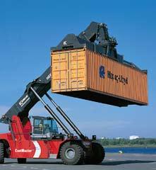
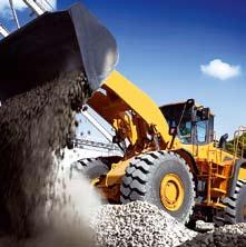
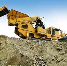
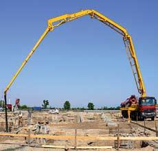
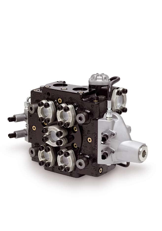
5 General Information The is a directional valve intended for machines such as large wheeled-loaders, mine loaders, fork-lift trucks, etc. It is designed for use in closed-centre (LS) hydraulic systems with variable pumps, and is suitable for tough operating conditions. Simple installation Good machine design and the right hydrau lic system gives a cost-effective installation, which in turn gives a competitive product. The pump and service ports in the are arranged in such a way that hosing and piping can be kept to an absolute minimum. The valve is equipped with double service ports at 180, which eliminates T-connectors and gives the shortest and simplest path to the cylinders. This also enables dimensions to be kept small, since only half the flow passes through each service port. Double pump s, located optimally for easy installation, enable the simple of a second pump. When the valve is mounted upright on the bottom plate good access for installation and service is obtained. Safety The is of robust construction. Many of the components are of the cartridge or module types, which facilitate servicing. It has both spool and poppet elements that give double safety in the case of hanging loads. The valve is also extremely well sealed, which prevents unintentional load sinking. Design The is a monoblock valve and is of LS design for variable pumps. It is cast in high quality material to enable it to withstand high pressures without deformation. The valve is of the spool type to give safe and precise regulation of the flow. To ensure tight sealing in the case of hanging loads, there is also a poppet element which, together with the spool, effectively blocks the hanging load. The poppet elements are controlled via a logic system and opened by pilot pressure. The poppet element also functions as a Load-hold check valve and as a prioritizing poppet on a port. The gallery system in the valve housing is generously dimensioned to give minimal pressure drop. This enables low pressure regeneration in order to save energy and avoid cavitation. Essential characteristics Excellent sealing: service ports closed by means of poppet valves. Not sensitive to temperature shocks: poppet-valve concept gives relatively large clearance between spool and bore. Good energy efficiency: low pressure drops for high function speeds; low energy consumption. Easy to install: designed with simple installation in mind. Optional float-position function: builtin, pressure-controlled float-position function eliminates the need for external components and signals. Great precision: low hysteresis gives precise control and good operator comfort. Pressure compensated lift and lowering functions Easy to service Long service life: efficient port-relief and anti-cavitation valves reduce the number of pressure peaks and cavitations in the system, thus prolonging the life of the machine. 5 Parker Hannifin
 Service port max. 400 bar* (5800 psi) Tank, static max. 20 bar (290 psi) Pressure in drain line recommended 1 bar (14.")
6 Technical Data Lifting eye Sequence valve Tank Spool section 1 Spool actuators PC-FPC Spool section 2 Load-hold check valve Pump Connection pipe at float position function For other s, see dimensional drawings on pages 16 to 23 Pressure Pump max. 375 bar* (5440 psi) Service port max. 400 bar* (5800 psi) Tank, static max. 20 bar (290 psi) Pressure in drain line recommended 1 bar (14.5 psi) Flow rate (recommended) Return from work port 1000 l/min (264 US gpm) at p =30 bar (435 psi) To work port 500 l/min** (132 US gpm) at p =20 bar (290 psi) Leakage from service port to tank From A- or B-port: max. 20 cm 3 /min (1.22 in 3 /min) at 100 bar (1450 psi), oil temperature 50 C (122 F) and viscosity 30 mm 2 /s (cst), fitted with Load-hold check valves. Installation While the valve can be mounted in any direction, it is best mounted upright (i.e. with lifting eye upwards) to give good access for servicing and enable simple handling. The base must be flat and stable to avoid stressing the valve on mounting. Filtration Filtration must be arranged so that Target Contamination Class 20/18/14 according to ISO 4406 is not exceeded. For the pilot circuit, Target Contamination Class 18/16/13 according to ISO 4406 must not be exceeded. Temperature Oil temperature, working range +20 to +90 C*** (68 to 194 F) Cold start The valve O-rings are of nitrile rubber as standard. In case of demands for high temperature resistance, please contact Parker for further information. Hydraulic fluids Best performance is obtained using mineral-base oil of high quality and cleanness in the hydraulic system. Hydraulic fluids of type HLP (DIN 51524), oil for automatic gearboxes Type A and engine oil type API CD can be used. Viscosity, working range mm 2 /s**** Technical information in this catalogue is applicable at an oil viscosity of 30 mm 2 /s and temperature of 50 C (122 F) using nitrile rubber seals. * Stated pressures are maximum absolute shock pressures at 10-bar tank pressure. ** Depending on choice of spool *** Product operating limits are broadly within the above range, but satisfactory operation within the specification may not be accomplished. Leakage and response will be affected when used at temperature extremes and it is up to the user to determine acceptability at these levels. **** Performance efficiency will be reduced if outside the ideal values. These extreme conditions must be evaluated by the user to establish suitability of the products performance. Weight Valve complete with spool actuator for hydraulic servo and with float position option: 95 kg (210 lb). 6 Parker Hannifin
7 Technical Information Connections Pump, tank and service-port s are of the SAE flange type. Valve block M6 [09] U6 [09] Connection (see pages 8, 9, 16-23) Flange/Thread (M-version) Flange/Thread (U-version) Pump, P SAE 1 1/4" -H* M14 SAE 1 1/4 -H* M14 Service ports A1, B1, A2, B2 SAE 1" -H* M12 SAE 1" -H* M12 Tank, T SAE 1 1/2" -S** M12 SAE 1 1/2" -S** M12 LS, Ps, psl, pl, pss, ps, D - M14x1,5-9/16-18 UNF Additional s A2, B2-1 1/16-12 UN - 1 1/16-12 UN Add. pump and gauge port T - M18x1,5-3/4-16 UNF All other gauge ports - M14x1,5-9/16-18 UNF Valve block M3 [09] U3 [09] Connection (see pages 8, 9, 16-23) Flange/Thread (M-version) Flange/Thread (U-version) Pump, P SAE 1 1/4" -S** M10 SAE 1 1/4" -S** M10 Service ports A1, B1, A2, B2 SAE 1 1/4" -S** M10 SAE 1 1/4" -S** M10 Tank, T SAE 1 1/2" -S** M12 SAE 1 1/2" -S** M12 LS, Ps, psl, pl, pss, ps, D - M14x1,5-9/16-18 UNF Additional s A2, B2-1 1/16-12 UN - 1 1/16-12 UN Add. pump and gauge port T - M18x1,5-3/4-16 UNF All other gauge ports - M14x1,5-9/16-18 UNF * High pressure (400 bar/6000 psi) ISO 6162 ** Standard pressure (340 bar/3000 psi) ISO 6162 Pressure drop Pressure drop measured with fully open spool intended for max. flow. p (bar) Pressure drop - P1/P2 to service port A/B p (bar) Pressure drop - service port to tank q (l/min) Pressure drop from pump P1/P2 to service port A/B q (l/min) Pressure drop from service port A/B to tank T. 7 Parker Hannifin
8 Hydraulic circuit diagram psl B1 A1 pl B2 A2 LS D B2 A2 T P D T P P pss ps Hydraulic circuit diagram for hydraulic remote controlled valve Pos. Function 1 Counter pressure valve 2 Section 1 3 Sequence valve, A1 4 Load-hold check valve, A1 5 Port relief valve, A1 6 Load-hold check valve, B1 7 Sequence valve, B1 8 Port relief valve, B1 9 LS drain 10 Section 2 Pos. Function 11 Float position device 12 Sequence valve, B2 13 Load-hold check valve, B2 14 Sequence spool float position 15 Check valve, priority 16 Restrictor, priority 17 Port relief valve, B2 18 Load-hold check valve, A2 19 Sequence valve, A2 20 Port relief valve, A2 8 Parker Hannifin
9 Hydraulic circuit diagram B1 A1 B2 A2 LS D p p B2 A2 p p T P D T P P Hydraulic circuit diagram for electro hydraulic remote controlled valve Pos. Function 1 Counter pressure valve 2 Section 1 3 Sequence valve, A1 4 Load-hold check valve, A1 5 Port relief valve, A1 6 Load-hold check valve, B1 7 Sequence valve, B1 8 Port relief valve, B1 9 LS drain 10 Section 2 Pos. Function 11 Sequence valve, B2 12 Load-hold check valve, B2 13 Port relief valve, B2 14 Load-hold check valve, A2 15 Sequence valve, A2 16 Port relief valve, A2 9 Parker Hannifin
10 Technical Information Connections [09] Also see table on page 7. M6 M3 U6 U3 Connections with metric threads. SAE 6000 psi Connections with metric threads. SAE 3000 psi Connections with UNF threads. SAE 6000 psi Connections with UNF threads. SAE 3000 psi p (bar) Pressure drop over counter pressure valve q (l/min) Counter pressure function [10] The valve can be equipped with a counter pressure valve in the tank to ensure that oil from the cylinders is used primarily to replenish the system. This is possible thanks to the generous gallery dimensions and anti-cavitation valves. The valve is factory set. MX MF5 MF9 No counter pressure valve in tank gallery Counter pressure valve set to 5 bar at 20 l/min Counter pressure valve set to 9 bar at 20 l/min Counter pressure symbol. See also complete circuit diagram, page 8 and 9, pos. 1. Load signal system [11] When a spool is actuated, a signal corresponding to the weight of the load is directed to the LS. When both spools are actuated, the greater of the two signals is directed to the LS. To enable the signal to be changed, it is drained continuously to tank via the load-signal drainage (LD), at approx. 0.8 l/min. LD Load-signal drainage, set to 0,8 l/min LS-drain Surface treatment (painted) [12] P X Default value - unless otherwise stated valve will be supplied painted with a single coat of black primer Unpainted For full corrosion protection, the valve must be painted with an outer coat. Prioritizing function [16] Section 1 can be pressure prioritized over section 2. This means that if there is a light load on section 2, heavier loads can be handled with section 1, e.g. so that an empty bucket can be tilted up at the same time as the main loading arms are lowered (prioritizing pressure approx. 50 bar). Prioritization is automatic and is controlled via pilot signal logic. PR1 Port A1 has priority over port B2 / Without prioritizing function (only M3 / U3 [09] ) A05 Prioritizing function blocked (only M6 / U6 [09] ) Priority function 10 Parker Hannifin
11 Technical Information Choice of spool The spool is the most important link between the actions of the machine operator and the movement of the controlled function. Parker therefore goes to great lengths to optimize spools for different flows, load conditions and functions. This ongoing development work results in the continual introduction of new spools. For this reason, it is not practical to list in this catalogue the different spools available at any one time. For assistance in the choice of spool, we therefore ask you to contact Parker directly. Spool function [21, 41] Parker spools are divided into different groups depending on their basic functions. D Double-acting spool for, e.g. double-acting cylinder. Blocked in the neutral position. D Db Dm PT T Db Double-acting spool with drainage B to T, which prevents pressure build-up in the B-port in the neutral position. The spool is used as a double spool in combination with, e.g. an over-centre valve. EA EAa Dm Double-acting spool with drainage A to T and B to T, which prevents pressure build-up in the neutral position. The spool is used as a double-acting spool in combination with, e.g. an overcentre valve. EA EAa Single-acting spool for, e.g. single-acting cylinder. Blocked in the neutral position. Service port B blocked. Single-acting spool for, e.g. single-acting cylinder. Blocked in the neutral position. Service port B blocked. Drainage of service port A to tank. M F A1B1 PT T A2B2 M Double-acting spool for, e.g. hydraulic motor. Service ports connected to tank (float position) in the neutral position. F Double-acting spool with fourth position in which both service ports are connected to tank (float position). Blocked in the neutral position. Spool designations [22, 42] Every spool is given a letter code, which is stamped on the spool. This facilitates identification of the spool when servicing is carried out. Area relationships [25, 45] The area relationship for the section in question is calculated by dividing the cylinder area connected to the B-port by the cylinder area connected to the A-port. When the big side of the cylinder is connected to the A-port, the area relationship is less than 1. The area relationship for a motor is Parker Hannifin
.")
 Connection thread: M14x1,5 or 9/16-18 UNF FPC FPC PC-FPC Both section 1 and section 2 have hydraulic, proportionally controlled, spring-centred spool actuators with a fourth")
12 Spool actuators PC PC PC pilot PC pilot Also see dimensional drawings on pages 16 to 19 for location of all s. PC-PC Both section 1 and section 2 have hydraulic, proportionally controlled, spring-centred spool actuators. Best controlled by a PCL4 remote control valve (see catalogue HY /UK). Breakaway pressure:* Final pressure:* 6.5 bar 18 bar (max 35 bar) Connection thread: M14x1,5 or 9/16-18 UNF FPC FPC PC-FPC Both section 1 and section 2 have hydraulic, proportionally controlled, spring-centred spool actuators with a fourth position for shifting the spool into the float position. Breakaway pressure:* Final pressure:* Pressure for float position: 6.5 bar 18 bar min 24 bar (max 35 bar) Connection thread: M14x1,5 or 9/16-18 UNF * The breakaway pressure refers to the pressure needed for the directional valve to open the pump to work port. The final pressure is the lowest pressure needed to effect full actuation of a spool in the directional valve. With the FPC spool actuator, the float position is obtained by further increasing the final pressure from max. 18 bar to min. 24 bar. The foregoing data must be taken into consideration when choosing control units, since the opening pressure of the control unit must be lower than the breakaway pressure of the spool actuator in order to avoid jerky starting and stopping. However, the control unit s final pressure must be higher than the final pressure of the directional valve in order to ensure that the spools can be fully actuated. 12 Parker Hannifin


13 Spool actuators EC EC D Also see dimensional drawings on pages 20 to 23 for location of all s. EC-EC Both section 1 and section 2 have electro-hydraulically, proportionally controlled, spring-centred spool actuators. The EC spool actuator is best controlled by means of a Parker electric remote-control system (see catalogue HY /UK). Voltage 12 V 24 V Breakaway current:* max 660 ma max 330 ma Final current:* min 1100 ma min 570 ma EC-FEC Both section 1 and section 2 have electro-hydraulically, proportionally controlled, spring-centred spool actuators. FEC is a proportionally controlled, spring-centred spool actuator with a fourth position for shifting the spool into the float position. The FEC spool actuator is best controlled by means of a Parker electric remote-control system (see catalogue HY /UK). Voltage 12 V 24 V Breakaway current:* max 660 ma max 330 ma Final current:* min 1100 ma min 570 ma Float position current: max ma max. 730 ma min ma min. 660 ma Solenoid (PS25): max 1450 ma, max 730 ma, 100% ED 100% ED Coil resistance at +20 C: 4,7 Ω 20,8 Ω Inductance: 8,8 mh 36,1 mh Tank pressure: max 15 bar max 15 bar Connection thread: M14x1,5 or 9/16-18 UNF Connector Type [4] The connector of the solenoid is of type: A AMP Junior-Timer type C D Deutsch type DT06-2P The connector must be ordered separately. FEC FEC * The breakaway current refers to the current needed for the directional valve to open the pump to work port. The final current is the lowest current needed to effect full actuation of a spool in the directional valve. With the FEC spool actuator, the float position is obtained by further increasing the final current, see table. The foregoing data must be taken into consideration when choosing control units, since the opening current of the control unit must be lower than the breakaway current of the spool actuator in order to avoid jerky starting and stopping. However, the control unit s final current must be higher than the final current of the directional valve in order to ensure that the spools can be fully actuated. 13 Parker Hannifin
![Technical Information Port relief valves [32A/B, 52 A/B] In spool sections the cartridge can be used as a combined portrelief and anti-cavitation valve in the service ports to protect the valve and](/docs-images/80/81379030/images/14-0.jpg "consumer from high system pressure and pressure surges. The cartridge is a direct-acting pressure relief valve with a fast response and good pressure characteristic.")

14 Technical Information Port relief valves [32A/B, 52 A/B] In spool sections the cartridge can be used as a combined portrelief and anti-cavitation valve in the service ports to protect the valve and consumer from high system pressure and pressure surges. The cartridge is a direct-acting pressure relief valve with a fast response and good pressure characteristic. The interchangeable cartridge is factory set. The make-up function enables oil to flow from the tank gallery to the service-port side in the event of negative pressure in the service ports, in order to prevent cavitation. Anti-cavitation valve type N2. Port relief valve type PA. No port-relief or anti-cavitation valve fitted. Connection service port to tank gallery is blocked, type Y2. Port relief valve type PAY. No port relief valve fitted. Service port connected to valve s tank gallery, type X2. 14 Parker Hannifin
15 Technical Information Port relief valve PA Combined port-relief and anti-cavitation valve fitted. Valve is factory set. PAY N2 Y2 X2 Port relief valve without anti-cavitation function fitted. Valve is factory set. Only anti-cavitation function fitted. No port-relief or anti-cavitation valve fitted. Connection service port to tank gallery is blocked. No port relief valve fitted. Service port connected to valve s tank gallery. p (bar) Port relief valve characteristics Pressure settings [33 A/B, 53 A/B] Setting range: bar. Pressure settings are made at a flow of 20 l/min through the valve. Load-hold check valve [34 A/B, 54 A/B] The valve is normally equipped with pilot operated Load-hold check valves for operations that demand low leakage. These check valves are optional if the machine is equipped with outer Load-holding valves q (l/min) N X3 Fitted with Load-hold check valve Without Load-hold check valve p (bar) Anti-cavitation characteristics Tank - service port B Tank - service port B2 Connectors Connectors are not included with spool actuators, and should be ordered separately as per the lists below or ordered from your local connector supplier. Spool actuators EC, FEC Suitable connectors for option A in pos [4] are: AMP Junior-Timer type C, , Bosch Assembly kits complete with pins and seals can be ordered on following kit numbers: 1 off K off K off K off K827 For more information, see catalogue HY /UK. Suitable connectors for option D in pos [4] are: Deutsch type DT06-2S q (l/min) 15 Parker Hannifin
16 Dimensional Drawings Hydraulic remote controlled (PC - PC) M3 and U3 51 (2.01) 218 (8.58) 167 (6.57) 135 (5.31) 103 (4.06) E mm (inch) Service port B2 Service port B1 201 (7.91) 152 (5.98) (4.06) 103 (4.06) 167 (6.57) (2.24) (4.25) Pump 103 Service port A1 Service port A2 Gauge port T Pilot s Tank Gauge port B2 260 (10.24) Gauge port B1 16 Parker Hannifin
17 Dimensional Drawings Hydraulic remote controlled (PC - PC) M3 and U3 127 (5.04) E mm (inch) 100 (3.97) (1.07) (2.38) 108 (4.29) 158 (6.27) (4.45) 151 (5.99) 201 (7.98) 110 (4.37) (1.71) (0.71) (0.99) (0.95) (3.30) 107 (4.25) 127 (5.04) 161 (6.39) (2.02) (5.36) 218 (8.65) 275 (10.92) 108 (4.29) Additional port P Additional port B2 Service port B2 Service port B1 Pump (9.21) 94 (3.73) 78 (3.10) (1.71) (0.67) Drain port D Additional port A2 Load signal LS Mounting hole M10 (4x) depth 20 (0.78) Service port A2 Service port A1 Gauge port A2 Gauge port A1 PC Pss PC Ps 17 Parker Hannifin
18 Dimensional Drawings Hydraulic remote controlled (PC - FPC) / (PC - PC) M6 and U6 51 (2.01) 218 (8.58) 167(6.57) 135 (5.31) 82 (3.25) E mm (inch) Only at FPC PC Pl PC Psl 103 (4.06) 167 (6.57) 57 (2.24) 201 (7.91) 152 (5.98) (4.06) Service port B2 Service port B1 Pump Service port A1 Service port A2 Gauge port T Tank Gauge port B2 260 (10.24) Gauge port B1 18 Parker Hannifin
19 Dimensional Drawings Hydraulic remote controlled (PC - FPC) / (PC - PC) M6 and U6 100(3.97) (1.07) 27 E mm (inch) Service port B2 Additional port P 43 (1.71) (9.21) Additional port B2 Service port B1 Pump 60 (2.38) (3.89) (4.45) 158 (6.27) 151 (5.99) (1.71) (4.29) (7.98) Drain port D (0.99) (0.95) (3.30) Additional port A2 Load signal LS Mounting hole M10 (4x) depth 20 (0.78) 135 (5.36) 107 (4.25) Service port A2 218 (8.65) 161(6.39) 275 (10.92) (2.02) 51 Service port A1 Gauge port A2 Gauge port A1 PC Ps PC Pss 19 Parker Hannifin
20 Dimensional Drawings Electro-hydraulic remote controlled (EC - EC) M3 and U3 E mm (inch) 218 (8.58) 167 (6.57) 135 (5.31) 103 (4.06) 51 (2.01) Service port B1 Service port B2 201 (7.91) 152 (5.98) (4.06) Pump 103 Service port A1 Gauge port T Service port A2 103 (4.06) 167 (6.57) Tank 57 (2.24) Gauge port B2 260 (10.24) Gauge port B1 20 Parker Hannifin
21 Dimensional Drawings Electro-hydraulic remote controlled (EC - EC) M3 and U3 127 (5.04) 125 (4.96) 100 (3.97) (1.07) 27 E mm (inch) 115 (4.57) 73 (2.90) 43 (1.71) 18 (0.71) (2.38) 108 (4.29) 158 (6.27) (4.45) 151 (5.99) 201 (7.98) Additional port P Additional port B2 Service port B2 Service port B1 Pump (0.67) (9.21) (3.89) (3.81) (2.46) (1.71) Drain port D PS (0.99) (0.95) (3.30) 107 (4.25) 127 (5.04) 130 (5.16) Additional port A2 Load signal LS Mounting hole M10 (4x) depth 20 (0.78) Service port A2 (2.02) (5.36) 218 (8.65) 275 (10.92) Service port A1 161 (6.39) Gauge port A2 Gauge port A1 Connector Type [4] A AMP Junior-Timer type C D Deutsch type DT06-2P 21 Parker Hannifin
22 Dimensional Drawings Electro-hydraulic remote controlled (EC - FEC) / (EC - EC) M6 and U6 51 (2.01) 218 (8.58) 167 (6.57) 135 (5.31) 82 (3.25) E mm (inch) Only at FEC 103 (4.06) 167 (6.57) 57 (2.24) 60 Service port B1 Service port B2 201 (7.91) 151 (5.94) 103 (4.06) Pump Service port A1 Gauge port T Service port A2 Tank Gauge port B2 260 (10.24) Gauge port B1 22 Parker Hannifin
23 Dimensional Drawings Electro-hydraulic remote controlled (EC - FEC) / (EC - EC) M6 and U6 127 (5.04) 125 (4.96) 100 (3.97) (1.07) 27 E mm (inch) Service port B2 73 (2.90) (1.71) (0.71) Additional port P Additional port B2 Service port B1 Pump (9.21) 62 (2.46) (1.71) (0.67) 232 Drain port D PS (0.99) (0.95) (3.30) 107 (4.25) 127 (5.04) 130 (5.16) (2.38) 60 (4.29) 108 (6.27) 158 (3.89) 98 EAdditional port A2 Load signal LS Mounting hole M10 (4x) depth 20 (0.78) Service port A2 (2.02) (5.36) 218 (8.65) 275 (10.92) (4.45) 151 (5.99) 112 (7.98) 201 Service port A1 161 (6.39) Gauge port A2 Gauge port A1 Connector Type [4] A AMP Junior-Timer type C D Deutsch type DT06-2P 23 Parker Hannifin
24 Parker Worldwide AE UAE, Dubai Tel: parker.me@parker.com AR Argentina, Buenos Aires Tel: AT Austria, Wiener Neustadt Tel: +43 (0) parker.austria@parker.com AT Eastern Europe, Wiener Neustadt Tel: +43 (0) parker.easteurope@parker.com AU Australia, Castle Hill Tel: +61 (0) AZ Azerbaijan, Baku Tel: parker.azerbaijan@parker.com BE/LU Belgium, Nivelles Tel: +32 (0) parker.belgium@parker.com BR Brazil, Cachoeirinha RS Tel: BY Belarus, Minsk Tel: parker.belarus@parker.com CA Canada, Milton, Ontario Tel: CH Switzerland, Etoy Tel: +41 (0) parker.switzerland@parker.com CL Chile, Santiago Tel: CN China, Shanghai Tel: CZ Czech Republic, Klecany Tel: parker.czechrepublic@parker.com DE Germany, Kaarst Tel: +49 (0) parker.germany@parker.com DK Denmark, Ballerup Tel: parker.denmark@parker.com ES Spain, Madrid Tel: parker.spain@parker.com FI Finland, Vantaa Tel: +358 (0) parker.finland@parker.com FR France, Contamine s/arve Tel: +33 (0) parker.france@parker.com GR Greece, Athens Tel: parker.greece@parker.com HK Hong Kong Tel: HU Hungary, Budapest Tel: parker.hungary@parker.com IE Ireland, Dublin Tel: +353 (0) parker.ireland@parker.com IN India, Mumbai Tel: IT Italy, Corsico (MI) Tel: parker.italy@parker.com JP Japan, Fujisawa Tel: +(81) KR South Korea, Seoul Tel: KZ Kazakhstan, Almaty Tel: parker.easteurope@parker.com LV Latvia, Riga Tel: parker.latvia@parker.com MX Mexico, Apodaca Tel: MY Malaysia, Shah Alam Tel: NL The Netherlands, Oldenzaal Tel: +31 (0) parker.nl@parker.com NO Norway, Ski Tel: parker.norway@parker.com NZ New Zealand, Mt Wellington Tel: PL Poland, Warsaw Tel: +48 (0) parker.poland@parker.com PT Portugal, Leca da Palmeira Tel: parker.portugal@parker.com RO Romania, Bucharest Tel: parker.romania@parker.com RU Russia, Moscow Tel: parker.russia@parker.com SE Sweden, Spånga Tel: +46 (0) parker.sweden@parker.com SG Singapore Tel: SK Slovakia, Banská Bystrica Tel: parker.slovakia@parker.com SL Slovenia, Novo Mesto Tel: parker.slovenia@parker.com TH Thailand, Bangkok Tel: TR Turkey, Istanbul Tel: parker.turkey@parker.com TW Taiwan, Taipei Tel: UA Ukraine, Kiev Tel parker.ukraine@parker.com UK United Kingdom, Warwick Tel: +44 (0) parker.uk@parker.com US USA, Cleveland (industrial) Tel: US USA, Lincolnshire (mobile) Tel: VE Venezuela, Caracas Tel: ZA South Africa, Kempton Park Tel: +27 (0) parker.southafrica@parker.com HYGE Ed Parker Hannifin Corporation. All rights reserved. European Product Information Centre Free phone: (from AT, BE, CH, CZ, DE, DK, EE, ES, FI, FR, IE, IL, IS, IT, LU, MT, NL, NO, PL, PT, RU, SE, UK, ZA) Fax: US Product Information Centre Free phone: Catalogue HY /UK. POD 09/2009 PC Your local authorized Parker distributor
PRS6 Auxiliary Valves
 Pressure Reducing Valves General Subject to alteration without prior notice. The curves and diagrams in this catalogue are typical examples only. While the contents of the catalogue are updated continuously,
VP04 Remote Control. Pneumatic Proportional Remote Control Valve
 Remote Control Pneumatic Proportional Remote Control Valve Catalogue Information Catalogue layout This catalogue has been designed to give a brief overview of the, and to make it easy for you to study
Transair: Advanced pipe systems For Nitrogen Applications
 Transair: Advanced pipe systems For Nitrogen Applications aerospace climate control electromechanical filtration fluid & gas handling hydraulics pneumatics process control sealing & shielding NITROGEN
Auxiliary Valve PRS6 Pressure Reducing Valve. Catalogue HY /UK June 2003
 Auxiliary Valve Pressure Reducing Valve June 2003 General Subject to alteration without prior notice. The curves and diagrams in this catalogue are typical examples only. While the contents of the catalogue
K220LS Mobile Directional Control Valve
 Proportional, Load Sensing, Pre-compensated Catalogue layout This catalogue has been designed to give a brief overview of valves, and to make it easy for you to study and choose from the different options
K220LS Mobile Directional Control Valve
 Proportional, Load Sensing, Pre-compensated Catalogue layout This catalogue has been designed to give a brief overview of valves, and to make it easy for you to study and choose from the different options
Directional Control Valves
 aerospace climate control electromechanical filtration fluid & gas handling hydraulics pneumatics process control sealing & shielding Directional Control Valves Series VA13 and VA15 3- and 5-port valves.
Remote Control VP04 Pneumatic Proportional Remote Control Valve zrc02. Catalogue HY /UK December, 2004
 Remote Control Pneumatic Proportional Remote Control Valve zrc02 Catalogue HY17-8356/UK December, 2004 Catalogue Information Catalogue layout This catalogue has been designed to give a brief overview of
Auxiliary Valve QDS6 Sequence Valve, 3-way. Catalogue HY /UK June 2003
 Auxiliary Valve equence Valve, 3-way Catalogue HY17-8542/UK June 2003 General ubject to alteration without prior notice. he curves and diagrams in this catalogue are typical examples only. While the contents
Directional Control Valves
 aerospace climate control electromechanical filtration fluid & gas handling hydraulics pneumatics process control sealing & shielding Directional Control Valves Series VA13 and VA15 3- and 5-port valves.
HPRV Proportional Relief Valve. Catalog 4190-HPRV
 HPRV Proportional Relief Valve Catalog 419-HPRV Contents Page 3... Introduction Page 4... Seal & Spring Options Page 5... Dimensions Page 6... Materials of Construction Page 7... How to Order 2 Introduction
Auxiliary Valve QDS6 Sequence Valve, 3-way. Catalogue HY /UK September 2005
 Auxiliary Valve equence Valve, 3-way Catalogue HY17-8542/UK eptember 2005 General ubject to alteration without prior notice. he curves and diagrams in this catalogue are typical examples only. While the
High Precision Regulators R210 / R220 / R230 Series
 High Precision Regulators R210 / R220 / R230 Series Catalogue no. PDE2542TCUK-ca WARNING FAILURE OR IMPROPER SELECTION OR IMPROPER USE OF THE PRODUCTS AND/OR SYSTEMS DESCRIBED HEREIN OR RELATED ITEMS CAN
Auxiliary valve QDS6 Sequence valve, 3-way. Catalogue (GB) (US) October 1998
 (US) October 1998") Auxiliary valve Sequence valve, 3-way Catalogue 9129 8542-02 (GB) 9129 8542-06 (US) October 1998 Sequence valve, 3-way Applications The sequence valve is designed to open or close a hydraulic pilot signal
Auxiliary valve Sequence valve, 3-way Catalogue 9129 8542-02 (GB) 9129 8542-06 (US) October 1998 Sequence valve, 3-way Applications The sequence valve is designed to open or close a hydraulic pilot signal
Xpress L90LS Directional Control Valve. Catalog HY /UK December, 2001
 Xpress L90LS Directional Control Valve Catalog HY17-8525/UK December, 2001 Catalogue HY17-8525/UK Technical Information Xpress - general information Xpress is a valve-customization service that enables
Update of trade weights data underlying the EERs and HCIs
 August 2017 Update of trade weights data underlying the EERs and HCIs The trade weights underlying the calculation of the effective exchange rates (EERs) of the euro and the harmonised competitiveness
Parker Tube Fabricating Equipment. Catalog TFE
 Parker Tube Fabricating Equipment Catalog 4190 - TFE Contents Small Bore Expert Training Tube Fabricating Equipment Page 3 Page 4 Page 6 Page 8 Page 10 Small Bore Expert Training Tube Benders Cutting &
ASB Accumulator Safety Blocks
 ASB Accumulator Safety Blocks For working pressures up to 350 bar Catalogue HY07-1241/UK Note: In line with our policy of continuing product improvement, specifications in this catalogue are subject to
Breathable Compressed Air
 aerospace climate control electromechanical filtration fluid & gas handling hydraulics pneumatics process control sealing & shielding Breathable Compressed Air ENGINEERING YOUR SUCCESS. Typical Hazardous
Directional Control Valve P70
 Directional Control Valve Open or Closed Centre Proportional Valve Series Catalogue HY17-8546/UK January, 2007 Catalogue Information Catalogue layout This catalogue is designed to give an overview of the
Summary Charts Scenario 3 - Low Change Scenario
 7/26/2016 U:\POUPU000.2015g_TD model 9\20160723TDM9\TDM_9p_Model_3_Sum_.Scen03_E70_20160726.xlsx Page 1 Summary Charts Scenario 3 - Low Change Scenario Equivalent domestic postage 70% priority domestic
Operating Instructions UCA Charging & Gauging Kit. For use with Piston, Bladder & Diaphragm Accumulators. Hydraulics. Effective: 01 July 2001
 Operating Instructions Charging & Gauging Kit Effective: 01 July 2001 For use with Piston, Bladder & Diaphragm Accumulators Warning FAILURE OR IMPROPER SELECTION OR IMPROPER USE OF THE PRODUCTS AND/OR
Summary Charts Scenario 1 - Base Scenario
 7/26/2016 U:\POUPU000.2015g_TD model 9\20160723TDM9\TDM_9p_Model_3_Sum_.Scen01_E70_20160726.xlsx Page 1 Summary Charts Scenario 1 - Base Scenario Equivalent domestic postage 70% priority domestic postage
THE WORLD COMPETITIVENESS SCOREBOARD 2011
 THE WORLD COMPETITIVENESS SCOREBOARD 2011 98.557 94.063 92.588 92.011 90.782 90.219 89.259 87.824 86.475 86.418 86.313 85.707 84.380 84.120 81.629 81.619 81.100 80.278 79.799 78.499 77.599 77.101 76.827
Directional Control Valve P70 Open or Closed Centre Proportional Valve Series. Catalogue HY /UK July, 2005
 Directional Control Valve Open or Closed Centre Proportional Valve Series Catalogue HY17-8546/UK July, 2005 Catalogue Information Catalogue layout This catalogue is designed to give an overview of the
Bladder Accumulators. EBV - ELG from 20 to 80 bar
 - ELG from 20 to 80 Main Features Operation principle Operation of the Parker Olaer gas loaded bladder accumulator is based on the considerable difference in compressibility between a gas and a liquid,
F130 Mobile Directional Control Valve
 Proportional, Open or Closed Centre Catalogue Description Catalogue layout This catalogue is designed to give an overview of the CF directional valve and to show how it can be customised to meet your needs
Proportional Pressure-Relief Cartridge Valve, Size 2...4
 Proportional Pressure-Relief Cartridge Valve, Size... Q max = l/min (6 gpm), p max = bar (58 psi) Direct acting, electrically operated Description proportional pressure-relief valves are direct acting
Inverse Prop. Pressure-Relief Cart., Size 2 4
 Inverse Prop. Pressure-Relief Cart., Size Q max = l/min (6 gpm), p max = bar (58 psi) Direct acting, electrically operated Description inverse proportional pressure-relief valves are direct acting screw-in
Industrial Hydraulic Valves. Directional Control, Pressure Control, Sandwich, Subplates & Manifolds, Accessories. Catalog HY /US
 Industrial Hydraulic Valves Directional Control, Pressure Control, Sandwich, Subplates & Manifolds, Accessories Catalog HY14-2500/US Industrial Hydraulic Valves WARNING USR RSPONSIBILITY FAILUR OR IMPROPR
HydroCOM: High energy savings and excellent controllability
 HydroCOM: High energy savings and excellent controllability Almost all applications require efficient capacity control systems Most of them simply waste energy, are slow and inaccurate. HydroCOM, however,
Inverse Proportional Pressure-Relief Cartridge, Size 10
 Inverse Proportional Pressure-Relief Cartridge, Size 1 Q max = 12 l/min, p max = 3 bar Seated pilot, spool-type main stage, damped design 1 Description inverse-proportional pressure-relief valves are size
Proportional Pressure-Relief Cartridge Valve, Size 2...4
 Proportional Pressure-Relief Cartridge Valve, Size... Q max = l/min, p max = 3 bar Direct acting, electrically operated 1 Description proportional pressure-relief valves are direct acting screw-in cartridges
Inverse Proportional Pressure-Relief Cart., Size 2 4
 Inverse Proportional Pressure-Relief Cart., Size Q max = l/min, p max = 5 bar Direct acting, electrically operated 1 Description inverse proportional pressure-relief valves are direct acting screw-in cartridges
Prop. 3-Way Pressure-Reducing Cart., Size 5 / SAE 08
 Prop. -Way Pressure-Reducing Cart., Size / SAE 8 Q max = 1 l/min (4 gpm), p max = bar (6 psi) Direct acting, electrically operated 1 Description proportional -way pressure-reducing cartridges are size
Max Sort Sortation Option - Letters
 Max Sort Sortation Option - Letters Western Europe Prices Product Code PS5 PS6 Austria* 0.330 7.550 0.330 7.400 Belgium* 0.370 3.700 0.370 3.540 Denmark* 0.620 5.350 0.620 4.215 Finland* 0.385 4.400 0.385
Shock Adsorbers. Series MC-SC
 aerospace climate control electromechanical filtration fluid & gas handling hydraulics pneumatics process control sealing & shielding Shock Adsorbers Series Catalogue PDE54TCUK July 011 WARNING FAILURE
F130 Mobile Directional Control Valve
 Proportional, Open or Closed Centre Catalogue Description Catalogue layout This catalogue is designed to give an overview of the CF directional valve and to show how it can be customised to meet your needs
Monoblock Directional Control Valve RMB 202
 Monoblock Directional Control Valve RMB 202 Key valve features RMB 202 is a 2-section mono block valve, especially designed for front-end loaders. The valve is prepared for quick connecting couplings,
Applications. What moves your world
 Digital Control Proportional Valves Series D92 High-performance pressure control valve with high dynamics and the ability to easily and exactly tune the pressure controller gain The pq-proportional valves
Inverse Proportional Pressure-Relief Cart., Size 2 4
 Inverse Proportional Pressure-Relief Cart., Size Q max = l/min, p max = 35 bar Direct acting, electrically operated Description Compact construction for cavity type AL 3/-6 UNF Operated by a proportional
Air Preparation System P3L Lite Series. Fully Modular with 1/4 Body Ports
 Air reparation System 3L Lite Series Fully Modular with 1/4 Body orts Catalogue DE661TCUK March 01 WARIG FAILURE OR IMROER SELECTIO OR IMROER USE OF THE RODUCTS AD/OR SYSTEMS DESCRIBED HEREI OR RELATED
directional control valve series cv691
 directional control valve series cv691 Contents Page 3 Page 4 Page 5 Page 6-7 Page 8 Page 9 Page 10 Page 11-12 General Information Technical Data Performance Curves Dimensions Relief Valve Advantages
Electrically Operated Pressure-Relief Cartridge, Size 10
 Electrically Operated Pressure-Relief Cartridge, Size 1 Q max = 14 l/min (37 gpm), p max = bar (5 psi) seated pilot stage, spool-type design, with remote contral port Z Series WUVPOC-2, WUVPLC-2 1 Description
Leak-Free Load-Control Valve SAE ½ psi flange
 Leak-Free Load-Control Valve SE ½ - 6000 psi flange Q max = 150 l/min [40 gpm], p max = 420 bar [6000 psi] leak-proof, two-stage hydraulic, SE-flange design 12--S... 1 Description Two-stage load-control
L90LS Mobile Directional Control Valve
 Proportional, Load Sensing, Pre-compensated Catalogue Information Catalogue layout In addition to general information and basic technical data, this catalogue contains descriptions of the many optional
Proportional Throttle Cartridges, Size 16
 Proportional Throttle Cartridges, Size 16 Q max = 5 l/min, p max = 5 bar, Q N max = 14 l/min at p 1 bar Two-Stage, with Seat-Valve Shut-Off 1 Description Normally closed Seat-valve shut-off from 1 Compact
PVK OPEN LOOP PUMPS. Bulletin E
 PVK OPEN LOOP PUMPS Bulletin 47025-E Table of Contents Performance Assurance page 3 Features and Benefits page 4-5 Specifications page 6 Pump Controls page 7 Table of Contents Curves Performance page 8
VPPL VARIABLE DISPLACEMENT AXIAL-PISTON PUMPS FOR INTERMEDIATE PRESSURE SERIES 10
 / ED VPPL VARIABLE DISPLACEMENT AXIAL-PISTON PUMPS FOR INTERMEDIATE PRESSURE SERIES OPERATING PRINCIPLE The VPPL are variable displacement axial-piston pumps with variable swash plate, suitable for applications
Leak free Pipe Rupture Valve for Excavators
 Leak free Pipe Rupture Valve for xcavators Series motion and progress Reference: 3 P 9575 1/11.6 Classification: 43.325.355...325.35 1/17 Contents Page 1 General description................................................................
Directional Control Valve L90LS Proportional, Load-Sensing and Pressure Compensated. Catalogue HY /UK July, 2005
 Directional Control Valve Proportional, Load-Sensing and Pressure Compensated July, 2005 Catalogue Information Catalogue layout In addition to general information and basic technical data, this catalogue
AREA TOTALS OECD Composite Leading Indicators. OECD Total. OECD + Major 6 Non Member Countries. Major Five Asia. Major Seven.
 Reference series Composite leading indicators OECD Composite Leading Indicators AREA TOTALS 7-03- 19 OECD Total 19 OECD + Major 6 Non Member Countries 19 Major Seven 19 Major Five Asia 19 Euro area 19
INVERS. Solenoid coil 24VDC 12 VDC Exm Exd Explosion protection marking:
 direct operated INVERSE function available Q max = 2 l/min p max = bar INVERS Description EPDB The direct operated proportional pressure relief valve is built as a slip-in cartridge fitted in a connecting
European Research Council
 European Research Council ERC Starting Grants 217 Outcome: Indicative statistics Reproduction is authorised provided the source 'ERC' is acknowledged. NB: In these graphs, 'grantee' refers to a candidate
VGU. Charging Set Vérificateur Gonfleur
 Charging Set Vérificateur Gonfleur Description (GB) SAFETY INSTRUCTIONS AND RECOMMENDATIONS: 1. Before any use of the tool, carefully read the directions and safety instructions in this guide. 2. In any
SDM to 8 sections monoblock valve D1WWDA02A
 SDM 1 SDM1 1 to 8 sections monoblock valve D1WWDA2A SDM1 Additional information This folder shows the product in the most standard configurations. Please contact Sales Dpt. for more detailed information
Load Controls Screw In Cartridge Valves Pressures to 350 bar (5000 psi) Flows to 190 l/min (50 USgpm)
 Flows to 190 l/min (50 USgpm)") Vickers Cartridge Valves Load Controls Screw In Cartridge Valves Pressures to 50 bar (5000 psi) Flows to 90 l/min (50 USgpm) Rev. 2/99 722 Contents MODEL DESCRIPTION TYP. APPLICATION PRESSURE bar (psi)
Vickers Cartridge Valves Load Controls Screw In Cartridge Valves Pressures to 50 bar (5000 psi) Flows to 90 l/min (50 USgpm) Rev. 2/99 722 Contents MODEL DESCRIPTION TYP. APPLICATION PRESSURE bar (psi)
MARIE SKŁODOWSKA-CURIE ACTIONS STATISTICS INDIVIDUAL FELLOWSHIPS
 MARIE SKŁODOWSKA-CURIE ACTIONS STATISTICS INDIVIDUAL FELLOWSHIPS Dernière mise à jour : Février 2019 1 EF ST EF CAR/RI SE GF European Fellowships Standard European Fellowships CAR/RI Society and Enterprise
1 LS unloading (control valve, orifice, none) 2 LS max pressure relief. 3 Spool type
 2 LS max pressure relief. 3 Spool type") Flow Control Valve Series LVM.. high flow rates (8 l/min) flow rates are unaffected by temperature change or when the higher load pressure alternates between the outlet ports proportional flow-sharing
Flow Control Valve Series LVM.. high flow rates (8 l/min) flow rates are unaffected by temperature change or when the higher load pressure alternates between the outlet ports proportional flow-sharing
damage due to improper handling, carelessness, or normal wear and tear damage due to tampering by persons lacking Porsche Design authorisation
 WARRANTY TERMS WARRANTOR Porsche Lizenz- und Handelsgesellschaft mbh & Co. KG, Grönerstraße 5, 71636 Ludwigsburg, Germany Every Porsche Design Timepiece is manufactured from the highest-quality materials
Function. Valve Size. Pilot Oil. p min. Bold: Designates Tier I products and options.
 Catalog HY14-255/US echnical Information ilot Operated ressure Reducing Valves Series VMY*6 General Series VMY*6 valves consist of the main stage with valve spools and the pilot stage with the proportional
Directional Controls
 Vickers Directional Controls Lever Operator Directional Control Valves DG17S-8-**-10 DG17S4-10 **-50 NF D08/D10, ISO-4401-08/10 Released 5/94 681 able of Contents General Information..................................................................................
Cartridge Valves Technical Information. Pilot operated check valves. Quick reference
 Quick reference Pilot to Open Model No. Description Flow* Pressure Page P RPC 4 NCS4/ Pilot Operated Check Valve, Pilot to Open l/min [ US gal/min] RPC 6 NCS6/ 5 l/min [7 US gal/min] CP45- SDC- l/min RPC
Double Pilot Operated Cartridge Check Valve, Size 8
 Double Pilot Operated Cartridge Check Valve, Size 8 Q max = 7 l/min (19 gpm), p max = 35 bar (5 psi) pilot operated, two-stage, spring-closed cartridge-type poppet valve Compact design for cavity type
Piston Accumulators. A Series 250 and 350 bar
 250 and 350 bar Introduction and eatures enefits enefits 2 4 1 3 8 10 9 7 1, 2 & 3. Shell and Caps Effective heat dissipation is vital for long seal life. Compact, rugged steel shell and end caps allow
Logic Elements Screw-in Cartridge Valves Pressures to 290 bar (4200 psi) Flows to 303 l/min (80 USgpm)
 Flows to 303 l/min (80 USgpm)") Vickers artridge Valves Logic Elements Screw-in artridge Valves Pressures to 9 bar ( psi) Flows to l/min (8 USgpm) Revised 9/98 7 ontents MODEL DESRIPTION TYPIL PPLITION PRESSURE bar (psi) RTED FLOW l/min
Vickers artridge Valves Logic Elements Screw-in artridge Valves Pressures to 9 bar ( psi) Flows to l/min (8 USgpm) Revised 9/98 7 ontents MODEL DESRIPTION TYPIL PPLITION PRESSURE bar (psi) RTED FLOW l/min
Fixed Displacement Plug-In Motor A2FE
 www.phphyds.com Series 6, axial tapered piston, bent axis design for mounting in mechanical gearboxes Sizes 28...355 Nom. Pressure up to 400 bar Peak Pressure up to 450 bar he fixed displacement plug-in
BW0500AO. ByWire Elements BW0500AO Element 4/3 with side ports IBW0500 Interface
 ywire Elements Element 4/3 with side ports IW5 Interface efore use, carefully read the GENERL INSTRUCTIONS FOR USE OF DIRECTIONL CONTROL VLVES 398SW5EN - 5--8 Technical data Nominal flow 5 l/min 3. US
LV LOADER DIRECTIONAL CONTROL VALVES INSTALLATION & USER GUIDE
 LV LOADER DIRECTIONAL CONTROL VALVES INSTALLATION & USER GUIDE SPECIFICATIONS: 10 gpm (38 lpm) Nominal Capacity. Rated up to 4000 psi (275 bar). Port Sizes-Inlet/Outlet #8SAE (3/4-16). Work Ports #8SAE
Premium T-Shirt. Premium T-Shirt -KIDS. T-Shirt Lady Fashion. Price Public 29,00 Availability: 5 to 7 work days
 Premium T-Shirt Price Public 29,00 Cotton Oficial KEYSI T-shirt Premium T-Shirt -KIDS Price Public 24,00 KIDS Cotton Oficial KEYSI T-shirt T-Shirt Lady Fashion Price Public 29,00 Cotton Oficial KEYSI T-shirt
STATISTICS
 DGAGRI-G2 23 Novembre 2017 W O R K I N G D O C U M E N T Horticultural Products FLOWERS AND ORNAMENTAL PLANTS STATISTICS 2006-2016 This statistical document has been prepared by Unit G.2 of DG AGRI, in
Full Range Pressure Compensating Variable Flow Control
 Engineering & Manufacturing Solutions Specifications: See flow chart for capacity. Rated for 3000 psi (207 bar). Weighs 7- ¾ lbs. (3.52 kg). 30-Micron Filtration Recommended. Torque to turn side lever
Optimization of a Proven Technology
 Optimization of a Proven Technology Second Generation closed-circuit breathing apparatus Symbiose The new BG 4 closed-circuit breathing apparatus is a symbiosis of reliable Dräger technology and practical
Directional Controls
 Vickers Directional Controls Directional Control Valves DG3V-3-*-60 Hydraulic Operated DG17V-3-*-60 Lever Operated DG18V-3-*-60 Air Operated DG20V-3-*-60 Cam Operated DG21V-3-*-60 Plunger Operated CETOP
4/3 Directional valve elements L85L1...(EDC-LV) with manual lever operated control with flow sharing control (LUDV concept) L85L1...
 with manual lever operated control with flow sharing control (LUDV concept) L85L1...") 4/3 Directional valve elements L8L1...(EDC-LV) with manual lever operated control with flow sharing control (LUDV concept) L8L1...(EDC-LV) RE 1831-17 Edition: 2.216 Replaces: 7.12 Size 6 Series Maximum
4/3 Directional valve elements L8L1...(EDC-LV) with manual lever operated control with flow sharing control (LUDV concept) L8L1...(EDC-LV) RE 1831-17 Edition: 2.216 Replaces: 7.12 Size 6 Series Maximum
MDC Series. Marine Grade 4-Way Directional Control Valve With Or Without Flow Control MDCF16TH304H MDC16TH404HB
 Engineering & Manufacturing Solutions Specifications: MDC rated for -4 gpm (-151 lpm) MDCF rated for -3 gpm (-114 lpm) Rate for 3 PSI (27 bar) Port Sizes #16 SAE (1-5/16-12) all ports Weighs 16 lbs. (7.3
NITROGEN CHARGING KIT type PC 11.1 E 04-11
 NITROGEN CHARGING KIT type PC 11.1 E 04-11 11.1.1 TECHNICAL DATA MAX OPERATING PRESSURE (PS): 600 BAR PRESSURE TEST (PT): 1.43 PS SCALE OF PRESSURE GAUGE: 4-10 - 16-25 - 60-100 - 250 (std.) - 400-600 bar
E 328 E 498 Tank top mounting Connection up to G1½ / -24 SAE and SAE 2 Nominal flow rate up to 600 l/min / gpm
 Return-Suction Filters E 8 E 98 Tank top mounting Connection up to G½ / - SE and SE Nominal flow rate up to 6 l/min / 8. gpm Description pplication For operation in units with hydrostatic drives, when
NITROGEN CHARGING KIT type PC 11.1 E 01-12
 NITROGEN CHARGING KIT type PC 11.1 E 01-12 11.1.1 TECHNICAL DATA MAX OPERATING PRESSURE (PS): 600 BAR PRESSURE TEST (PT): 1.43 PS SCALE OF PRESSURE GAUGE: 4-10 - 16-25 - 60-100 - 250 (std.) - 400-600 bar
R S 280 is a modular parallel sect. Directional Control Valve RS RS In relation to its flow capacity its installation
 Directional Control Valve RS 280 3 RS 2802 3102RS28001 R S 280 is a modular parallel sect nal valve. Suitable applications are medium sized and big truck loaders, medium sized backhoe loaders and other
L125 SERIES POST-COMPENSATED SECTIONAL LOAD SENSE VALVE
 L15 SERIES POST-COMPENSATED SECTIONAL LOAD SENSE VALVE TAKE CONTROL Take control with Muncie Power Products L15 directional control valve. The L15 is constructed with high-grade, iron castings and nickel-plated
Medium-sized vessels water connection. White paper
 Medium-sized vessels water connection White paper Flamco B.V. January 2017 Medium-sized vessels water connection In practice you will find expansion vessels with the water connection on bottom, and with
Displacement 12, , Maximum flow rate (at 1450 rpm) bar.
 bar.") 00/07 ED PVD VARIABLE DISPLACEMENT VANE PUMPS SERIES 0 OPERATING PRINCIPLE The PVD pumps are variable displacement vane pumps with a mechanical type of pressure compensator. They allow instantaneous adjustment
00/07 ED PVD VARIABLE DISPLACEMENT VANE PUMPS SERIES 0 OPERATING PRINCIPLE The PVD pumps are variable displacement vane pumps with a mechanical type of pressure compensator. They allow instantaneous adjustment
Displacement. from 2 up to 6 sections balanced, unbalanced from 0.8 to 31 ccm FLOW DIVIDERS
 Displacement from 2 up to 6 sections balanced, unbalanced from 0.8 to 31 ccm FLOW DIVIDERS DP Catalogue of flow dividers DP TABLE OF CONTENTS GENERAL DESCRIPTION........................................................................................................
FLUID POWER FLUID POWER EQUIPMENT TUTORIAL OTHER FLUID POWER VALVES. This work covers part of outcome 2 of the Edexcel standard module:
 FLUID POWER FLUID POWER EQUIPMENT TUTORIAL OTHER FLUID POWER VALVES This work covers part of outcome 2 of the Edexcel standard module: UNIT 21746P APPLIED PNEUMATICS AND HYDRAULICS The material needed
Proportional Directional Valve System
 roportional Directional Valve System Sectional Design and Flow Sharing rinciple Reference: 31--959-EN-3 Stand: 9.216 1/2 2/2 31--959-EN-3/9.216 Contents age 1 General... 5 1.1 Description... 5 1.2 Advantages...
PIN Flash 18 - Background tables
 PIN Flash 18 - Background tables Definition of deaths on urban/rural rural roads How the urban/rural distinction is made in the statistics that your country provides to CARE CARE Deaths on rural roads
Pilot Operated Check Valves Catalog Quick Reference
 Quick Reference Pilot to Open Model No. Description Flow* Pressure Page RPC NCS/3 Pilot Operated Check Valve, Pilot to Open.5 l/min [5. US gal/min] RPC NCS/3 35 l/min [9.3 US gal/min] CP5- SDC-3 3 l/min
I. World trade in Overview
 I. Table I.1 Growth in the volume of world merchandise exports and production by major product group, 1995-3 ( change) 1995-21 22 23 World merchandise exports 7. -.5 3. 4.5 Agricultural products 3.5 2.5
BUTTERFLY VALVES. Toll Free (877) - ICFLUID -2-
 - ICFLUID -2-") BUTTERFLY VALVES 1. General HyrdoWer is a globally recognized manufacturer of power unit accessories. They have become specialists in the design of Butterfly Valves and Hydraulic Compensators. The shut
BUTTERFLY VALVES 1. General HyrdoWer is a globally recognized manufacturer of power unit accessories. They have become specialists in the design of Butterfly Valves and Hydraulic Compensators. The shut
WORKHOLDING APPLICATION BOOKLET
 WORKHOLDING APPLICATION BOOKLET Applications and advantages of using minibooster hydraulic pressure intensifiers MINIMUM SIZE MAXIMUM POWER B-GB Workholding 2018.04 1 of 20 2 of 20 B-GB Workholding 2018.04
TERMINAL BLOCK SUMMARY
 TERMINAL BLOCK SUMMARY TERMINAL BLOCK SUMMARY TERMINAL BLOCK SUMMARY FEEDTHROUGH TERMINALS FUSE TERMINALS DISCONNECT TERMINALS MICRO TERMINALS CIRCUIT BREAKERS PRODUCT INFORMATION Feedthrough Terminals
BERMAD Fire Protection Hydraulic Control Valves
 BERMAD Fire Protection Hydraulic Control Valves Control Solutions with the Power to Protect BERMAD - The Company Since its foundation in 1965, BERMAD has focused its efforts on innovation, quality and
PRESSURE SEQUENCE VALVE TYPE UZK
 PRESSURE SEQUENCE VALVE TYPE UZK Size 10, 20, 30 31,5 MPa up to 450 dm 3 /min WK 450 414 04. 2000r. Pressure sequence valves type UZK are used for switching a system or part of a system off when a set
UPA All fluids. Full flow All stainless steel
 UPA All fluids Full flow All stainless steel High-quality, efficient... Applications Quick connections for fluid circuits: - on distribution manifolds, - on fillers, - in your washing plants, - for your
Upgrading Bio-Plex Manager 4.1, 5.0, or 6.0 Software to Bio-Plex Manager 6.1 Software
 Upgrading Bio-Plex Manager 4.1, 5.0, or 6.0 Software to Bio-Plex Manager 6.1 Software For technical support, call your local Bio-Rad office, or in the US, call 1-800-424-6723. Bio-Rad Laboratories, Inc.,
PTS1120TSJB PTS2120TSTSJB
 Engineering & Manufacturing Solutions Specifications: 18 gpm (68.0 lpm) Nominal Capacity. Rated up to 3000 psi (207 bar). Port Sizes: -Inlet/Outlet #12 SAE. -Work Ports #10 SAE. 10 Micron Filtration Recommended.
Confidence through experience. Track record as of 30 June 2012
 Confidence through experience Track record as of 30 June 2012 Harvesting the full potential of wind Confidence is built through experience. During more than 30 years in the wind industry we have installed
Global Construction Outlook: Laura Hanlon Product Manager, Global Construction Outlook May 21, 2009
 Global Construction Outlook: Short-term term Pain, Long-term Gain Laura Hanlon Product Manager, Global Construction Outlook May 21, 2009 What This Means for You The world is set to be hit this year with
UPB All fluids. Full flow All stainless steel
 UPB All fluids Full flow All stainless steel High-quality, efficient... Applications Quick connections for the following circuits: - draining, - filling, - fluid transfer, - etc. Fluids Wide range of fluids,