Annex 1 Gas circulation / purification system
|
|
|
- Eleanore Rice
- 5 years ago
- Views:
Transcription
 These detectors operate with different gas fillings: ultra-clean hydrogen in TPC and Ar+1%CH 4 in the tracker.")
1 Annex 1 Gas circulation / purification system In the proposed experiment, a high pressure hydrogen TPC and a large aperture Forward Tracker are placed in one vessel which could stand for pressures up to 25 bar (Fig.1) These detectors operate with different gas fillings: ultra-clean hydrogen in TPC and Ar+1%CH 4 in the tracker. The main body of the detector is made of normal steel which is not clean enough for the purposes of this experiment. Therefore, TPC and PC have individual clean volumes (made of stainless steel with thin beryllium and capton windows) surrounded by technical Argon (Fig.1). So, there are three different gas volumes where the pressure should be permanently equalized. Also, this pressure should be stable, and its value should be known with 0.01% absolute precision. The measurements will be performed at 20 bar and at 4 bar gas pressure. In order to avoid the losses of the ionization electrons during the drift time, the contamination of the H 2 gas by any electro-negative gas (O 2, H 2 O) should be reduced to a level below 1 ppm. This will be achieved by continuous H 2 purification with a special cryogenic gas purification system which eliminates gas impurities down to ~ 0.1 ppm. The system satisfying the above formulated requirements has been designed at PNPI. This design is based on the experience from operation of a hydrogen gas circulation/purification system previously constructed for the MuCap experiment at PSI [1]. Fig. 1. Schematic view of the TPC & FT detector with three gas volumes (H2, Ar+1%CH4, and Ar) in a common high pressure vessel. 1

2 Fig. 2. Simplified diagram of the gas circulation/purification system. Fig.2 shows a simplified diagram of the gas system designed for this experiment. Fig.3 presents the complete technical design of this system. It consists of three independent subsystems. 1. The hydrogen subsystem for TPC, volume about 1 cubic meter. The gas circulation is maintained by compressor C1. This subsystem: Purifies hydrogen in TPC down to < 1 ppm impurities level with a gas flaw of 15 normal liters per minute; Stabilizes hydrogen pressure in the detector with stability 2 mbar in the range 4-20 bar with the help of mass-flow controllers MFC1 and MFC2 and reserve volumes RV1 and RV2 suppressing the pressure oscillations before and after compressor C1;. Gives possibility to analyze the gas purity in TPC on a sub ppm level using a water analyzer and an oxygen analyzer;. Evacuates hydrogen into the hydrogen reserve volume with typical filling/evacuation time of hours. 2. The Argon+methane subsystem for the Forward Tracker operating in the same way as the hydrogen subsystem. The gas purification is adopted for the argon+methane gas mixture and includes periodically replacing of some fraction of the gas mixture by a fresh gas mixture. 3. The Argon supply subsystem does not use gas circulation. The pressure in this subsystem is regulated by adding and venting argon via electromagnetic valves. This pressure is equalized with the pressure in TPC@FT during all operations with the gases (circulation, filling and evacuation of hydrogen and arogon+methan gas mixture). 2
3 Slow control system provides minimization (1-2 mbar) of the differential pressure between all subsystems during normal gas circulation and during filling-evacuation procedure. Fig. 3. Complete technical design of the gas circulation/purification system MV manual valve SV remotely operated valve PT pressure transmitter (sensor) for absolute and differential pressure measurements MFC mass-flow controller PSV release safety valve RV reserve volume PCV reduction valve CV check valve PIS pressure indicator CO capillary throttle C - compressor Reference 1. A circulating hydrogen ultra-high purification system for the MuCap experiment. V.A. Andreev et al. NIM A578 (2007)
4 Annex 2 Test run with a TPC prototype A2 hall, 720 MeV electron beam, August- September 2017, The main goal of the test run was to investigate performance of the TPC in the electron beam. In particular, one had to answer the following questions: How much the recoil proton energy resolution is deteriorated in presence of the electron beam with intensity up to 2 MHz? What is the background in TPC and occupancy of the read out channels? Would it be possible to operate TPC in the self-triggering mode? Also, it was important to obtain the electron beam with requested parameters: strongly reduced intensity ( 2MHz, 100 khz, 10 khz), 0.5 mrad (sigma) divergence, 0.5 mm (sigma) size, stable beam spot position and intensity. In addition, the pixel detectors were to be tested for control of the beam size and position. The experimental setup used in this test run was a TPC constructed within the program FAIR at GSI as an ACTAR2 prototype of the Active Target for the R3B experiment. Previously, it has been used in a test experiment at GSI with 700 MeV/u heavy ions beams. This TPC is similar to the TPC in our proposal (though smaller in size and with lower pressure), and it could help to answer the formulated above questions. Normally, this TPC operates with hydrogen gas filling up to 10 bar pressure, but it was filled with the gas mixture of He+4%N 2 in this run because of safety restrictions to work with hydrogen at this stage of construction of the experimental setup. However, as it was shown by our MC simulation, the ionization properties of this gas mixture are similar to those in hydrogen. Therefore, the obtained results could be used for predictions for the hydrogen TPC performance designed for the main experiment. A schematic view of the layout of the ACTAR2 prototype is shown in Fig 1. The system of the TPC electrodes the cathode, the grid, and the sectioned plane of anodes is placed inside a 40 liters cylindrical aluminum vessel. The semi-spherical beam windows of beryllium, 0.5 mm thick, 70 mm in diameter are mounted on the forward and backward flanges of the vessel. The anode-grid distance is 3 mm, the grid-cathode distance (the drift gap) is 220 mm. The field uniformity in the drift gap is formed by a set of 11 field shaping rings. The grid is made of 55 μm steel wires wound with 1 mm step on a stainless steel ring (204 mm internal diameter). The anode outer diameter is 200 mm. The anode electrode is split into 66 segments (Fig. 2). The measurements were performed with 10 bar and 5 bar gas pressure. The potentials on the cathode and on the grid, as well as the corresponding drift velocities are shown in Table 1. The anode is at zero potential. 4
. Fig. 2. Layout of the ACTAR2 prototype anodes.")
5 Table1 ACTAR2 prototype operational conditions in the test run. Gas pressure HV cathode HV grid Drift velocity Cathode-grid Drift velocity Grid-anode 10 bar - 14 kv mm/µs 6 mm/µs 5 bar - 9 kv mm/µs 9 mm/µs Fig. 1. Schematic view of the ACTAR2 prototype (side view). Fig. 2. Layout of the ACTAR2 prototype anodes. An 241 Am α-source is deposited on the cathode of the chamber opposite to the black spot on the anode number 7. The outer diameter of the anode plane is 200 mm. The central pad is 20 mm in diameter. Signals from all anodes are read out by independent electronics channels including preamplifiers, amplifiers, and Flash-ADCs (14 bit, 250 MHz). The signal shaping was 5
 Fig. 3. Signal at the output of the amplifier corresponding to a delta function input signal.")
6 optimised to get maximal signal-to-noise ratio. The resulted energy resolution was around 20 kev in all anode channels. Fig. 3 illustrates the shaping of the signals in the amplifiers (reaction on a delta function input signal) Fig. 3. Signal at the output of the amplifier corresponding to a delta function input signal. The beam tracking detectors were placed upstream of the TPC. These were 4 planes of 3x3 mm 2 pixel detectors (0.05 mm thickness, 100 x 80 µm 2 pixels). In addition, there were one scintillator upstream and one scintillator downstream of TPC. The experimental setup was implemented in the GIANT4 MC model (Fig.4) Fig. 4. The experimental setup as implemented in the GIANT4 Monte Carlo model. The experimental setup was installed in A2 hall downstream of the Cristal Ball/Taps setup. (Fig.5). A temporary electron beam line was constructed specially for this 6
, and divergence was 1mrad, which is close to the requirements of the experiment.")

7 experiment. The beam was focused on the input of the ACTAR2 setup. The parameters of the beam were measured with the pixel detectors (Fig.6). According to these measurements, the size of the beam spot was 250 µm (sigma), and divergence was 1mrad, which is close to the requirements of the experiment. Critical for this experiment was stability of the electron beam at unusually for MAMI low beam intensity (2MHz, 100 khz, and 10 khz). All these options were successfully tested in the run. It was demonstrated that MAMI can provide practically ideal electron beams for this experiment. The only concern was some long term instability of the beam spot. Therefore, it should be under control in the main experiment with feed back to the accelerator control room. Fig.5. Plan of A2 hall. The ACTAR2 setup is installed downstream of the Cristal Ball/Taps setup. A temporary electron beam line was constructed for this test run. Also shown is a new electron beam line designed especially for this experiment. 7
.")

8 Fig. 6. Beam telescope - four planes of pixels ( top left). Beam spot as seen by pixels (top right). Pixel map projections in Y0 (bottom left) and X0 (bottom right ) planes. The x-axis in the figure is the pixel numbers. (the pixel width is 80 µm and 100 µm for Y0 and X0 planes, respectfully). Recoil energy resolution Every beam particle produces ionization in TPC along its track with fluctuations caused mostly by emission and absorption of delta electrons. With the total drift time 100 µs and the beam intensity 2 MHz, the ionization produced by ~200 particles remains permanently in the TPC volume. This results in the beam ionization noise in addition to the electronics noise. Such processes are included in the GIANT4 MC model. With this model, the expected beam ionization noise was calculated for the ACTAR2 TPC. Fig.7 shows the simulated 1.5 MeV recoil signals at the central anode channel mixed with the beam ionization noise at 1.5 MHz and 0.7 MHz beam rates.the measured width of the signal amplitude distribution gives the beam ionization noise. To obtain the total noise, one should add the electronics noise which is 20 kev (sigma) in our case. 8
9 Fig.7. Simulated 1.5 MeV signals on top of the beam ionization noise for 1.5 MHz (left) and 0.7 MHz (right) beam rates. The MC simulation was performed for various beam rates and experimental conditions. The obtained results are presented in Fig.8 a,b,c. Fig.8a. Beam ionization noise in function on the beam rate calculated for the He + 4%N 2 gas mixture ( 10 bar) and for pure hydrogen ( 10 bar and 20 bar). Drift gap 220 mm. Drift velocity 2.75 mm/µs. 9
10 Fig.8b. Beam ionization noise in function on the beam rate calculated for drift gaps 220 mm and 350 mm He + 4%N 2 gas mixture (10 bar). Drift velocity 2.75 mm/µs. Fig.8c. Beam ionization noise in function on the beam rate calculated for various drift velocities. He + 4%N 2 gas mixture ( 10 bar). drift gap 220 mm. The results of the MC simulations could be summarized as follows: The beam noise is increasing with beam rate as root square of the rate; The beam noise is nearly proportional to the gas pressure; The beam noise is increasing slightly with the total drift gap; The beam noise is increasing slightly with the drift velocity; The beam noise in hydrogen is less than in the He+4%N 2 mixture by ~ 20%. The measurements of the noise in the test run have been done with pulse generator signals sent simultaneously to the inputs of all anode channels. The extraction of the signals and determination of the width was done with the same algorithm as in the MC studies. The measurements were performed at 10 bar and 5 bar gas pressure at various beam rates. These measurements showed that the beam noise appears mostly in the central anode pad 65 and too much less extent on the nearest ring (pad 66). The noise on all other pads is practically insensitive to the beam rate. The results of the noise measurements on the central pad are presented in Fig.9 together with the MC results. 10
11 Fig.9. Comparison of the noise at the central pad measured at various beam rates with MC calculations. He + 4%N 2 gas mixture (5 bar and 10 bar). Drift gap 220 mm. Drift velocity 2.75 mm/µs for 10 bar and 3.14 mm/µs for 5 bar gas pressure. Note that the calculated beam ionization noise was summed up with the electronics noise in this figure for comparison with the experimental data. One can see that the experimental results are in reasonable agreement with the Monte Carlo calculations. Based on this agreement, we can use the MC model for prediction of the beam noise conditions in our main experiment. The results are presented in Fig. 10. Fig.10. MC prediction of the beam ionization noise on the central pad for the main experiment. Pure hydrogen. 20 bar and 4 bar gas pressure. Drift gap 400 mm. Drift velocity 4 mm/µs. According to these calculations, The expected noise on the central pad in the main experiment is ~ 90 kev at 20 bar and ~ 30 kev at 4 bar hydrogen gas pressure. TPC rates in self-triggering mode The rates of the self-triggers were measured with the following definition of the trigger signal. The thresholds in each anode channel were set at 300 kev. The trigger was generated when there was at least one signal exceeding this threshold. After that, the information was read out from all anode channels. Note that the energy scale was calibrated by the position of the 241 Am alpha peak in the ADC channels. 11
12 The following results have been obtained at 1.6 MHz (10 bar pressure): Total rate of self-triggers Signals from the central pad with no signals from other pads Signals from the central pad in coincidence with any other pad 8 Hz 5.6 Hz 0.6 Hz The observed number of self-triggers includes also the real e 4 He elastic scattering as well as the inelastic reactions on 4 He and Nitrogen. An example of such events is presented in Fig.11 showing a long range track started from the central pad. Fig.11. Display of a long range track observed in the TPC. The calculated rate of the e 4 He elastic scattering events in the covered Q 2 range (recoil 4 He energy 300 kev) is 3.5Hz, the majority of these events being within the central pad. That means that the observed self-trigger rate is determined mostly by the physics reactions with only little contribution from the beam ionization noise. This statement is supported by direct measurement of the amplitude spectrum of the signals from the central pad (Fig.12). 12
13 Fig. 12. Amplitude distribution of the signals from the central pad. Scale is in the ADC channels,1 ch=22 kev. The red curve fit with 1/t 2 distribution combined with a Gaussian centered at 300 kev. In the main experiment, the self trigger rate will be determined by the rate of the ep-elastic cross section in the selected Q 2 range. With the beam rate 2 MHz and the threshold at 300 kev, it will be ~ 30 Hz at 20 bar and ~ 6 Hz and 4 bar hydrogen gas pressure. Note that the threshold at the central pad should be probably increased in the 20 bar runs up to ~ 450 kev due to higher beam ionization noise ( five σ noise =~90 kev) that will reduce the trigger rate to ~ 20 Hz. Anyhow, we can formulate a very important conclusion for planning the read out system in the main experiment: For triggering, one can use the self-trigger from TPC with the mean rates 50 Hz. Conclusions from the test run MAMI accelerator provides practically an ideal electron beam for this experiment. The beam ionization noise produced in TPC by the electron beam is in agreement with the Monte Carlo simulations. No unexpected sources of the background in TPC has been manifested. This allowed to make predictions for the noise and background conditions in the main experiment. For triggering, one can use the self-trigger from TPC with the mean rates 50 Hz. The above conclusions have been drawn from measurements with TPC filled with the 4He +4%N 2 gas mixture. It would be important to repeat these measurements with hydrogen gas in TPC, resolving for that the safety problems. Another important task for the next test run is testing and calibration of the beam counters which should operate in the 2 MHz beam with minimum dead time to provide high precision information on the absolute beam rate. 13
14 Participants in the test run and data analysis Mainz: Patrik Adlarson, Marco Dehn, Peter Drexler, Andreas Thomas, Frederik Wauters, Vahe Sokhoyan, Achim Denig, Michael Ostrick, Niklaus Berger, Oleksandr Kostikov Maik Biroth,Edoardo Mornacchi, Jurgen Ahrens. PNPI: Alexey A. Vorobyov, Alexander Vasilyev, Petr Kravtsov,Marat Vznuzdaev, Kuzma Ivshin, Alexander Solovyev, IvanSolovyev, Alexey Dzyuba, Evgeny Maev, Alexander Inglessi,Gennady Petrov GSI: Peter Egelhof, Oleg Kiselev College of William and Mary: Keith Griffioen, Timothy Hayward 14
15 Annex 3 Study of gas gain in a CSC prototype at high pressure The FT consists of two pairs of Cathode Strip Chambers X 1 /Y 1 and X 2 /Y 2. Each chamber is a symmetric MWPC with 2.5 mm gap between the cathode and the anode planes. The size of the chamber is 600x600 mm 2. The readout is from both cathode planes. The anode wire plane contains 30 µm wires spaced by 3 mm. Both cathode planes are made with 100 µm wires wound with 0.5 mm step. The cathode wires are orthogonal to the anode wires in one cathode plane and inclined by 45 deg. in the other cathode plane. The wires in the inclined cathode plane are grouped into 10 mm strips. In the cathode plane with orthogonal to the anode wires, 2 mm strips are formed by joining together 4 wires. The width of all strips should be identical within ± 20 µm. This allows determination of the center-of gravity of each detected signal with a precision ~1% of the strip width (σ proj ~ 30 µm) assuming the signal to noise ratio S/N 100 and the electronics amplification uniform within 1% in each readout channel. The ionization produced in a CSC plane by a relativistic particle is ~ 1000 electrons at 20 bar pressure. The electronics noise is ~ 1000 electrons. Therefore, to obtain the ratio S/N 100, the CSC gas gain should be ~100. However, the detected charge is only ~30% of the total charge. Therefore, the gas gain should be at least 300 but better It is not trivial to obtain such gas gain at 20 bar pressure with 600 mm long anode wires. In particular, it is not possible in pure hydrogen. That is why we shall use the Ar +CH 4 gas mixture. There is very limited information on gas amplification at high gas pressure. To our knowledge, there were only studies of gas gains in a proportional cylindrical counter performed by an Australian group in They could reach the 10 3 gas gain at 28 bar pressure in the gas mixture Ar + 2% CH 4 (Figure below). Still it was an open question if this result could be reproduced in multiwire proportional chambers. For that purpose, we have performed some tests using a small size prototype of the CSC designed for the Forward Tracker (Fig.1) with the gas mixture Ar+ 1% CH4. 15
 and also with cosmic muons. Fig.")

16 Fig.1. CSC prototype prepared for measuring gas gain at high pressure. The measurements have been done with a 55 Fe x-ray source (6 kev) and also with cosmic muons. Fig. 2 shows the amplitude spectrum measured with the 55 Fe x-rays at 20 bar pressure HV= 6100 V. The peak position corresponds to 10 3 gas gain. Fig Fe source photons amplitude spectrum in 99%Ar+1%CH4 gas mixture at 20 bar. Peak position in 880 ch corresponds to the GG


17 Fig.3. Amplitude spectrum measured with cosmic muons (left) and with 55 Fe x-rays (right). P=5 bar. HV=2950V. GG =600 corresponds to channel 700. Fig.3 shows comparison of the amplitude spectrum measured with the 55 Fe x-rays with that measured with cosmic rays at 5 bar pressure. The initial ionizations are comparable for both cases. However, the mean amplitude in the cosmic ray spectrum proved to be by ~20% lower due to different reaction of the amplifier on continuous tracks from muons and short tracks from x-rays. Conclusions: These tests demonstrated possibility to reach the necessary gas gain GG=300 in terms of detected charge at 20 bar pressure. 17
18 Annex 4. Trigger, readout, and selection of true ep collisions Trigger The choice of the trigger is one of the critical points in the experiment. Fortunately, we have possibility to use the TPC recoil proton signals for triggering the readout system. This is the most safe and effective triggering option. As it was demonstrated in the test run, the background in TPC produced by the electron beam is rather low. The self-trigger rate from TPC operating at 10 bar pressure was ~ 8Hz at the beam intensity 1.6 MHz, the trigger being defined as any signal exceeding the 300 kev level in any of 66 anode pads. Most of this rate is due to elastic e 4 He scattering (~3.5 Hz ) and from inelastic reactions on 4 He and Nitrogen. That means that in the main run with hydrogen in TPC, the self trigger rate would be determined mostly by the ep elastic scattering events. The expected rate of such events is N ep_elastic = 30 Hz with the threshold set at 300 kev at P=20 bar and 6 Hz at P=4 bar. Readout The presented here readout scheme was designed specially for this experiment. The main features of this system: Triggering by signals from TPC (self-triggering). The maximal average trigger rate: 50 Hz. After receiving a trigger signal, the information from all detectors appeared in a regulated time interval (up to 655 µs) before arrival of the trigger is readout from the pipeline and sent to DAQ. The number of readout channels: 24 channels from TPC and 1920 channels from Forward Tracker. The readout system provides continuous data flow without dead time. This readout scheme is based on some previous developments at the PNPI Electronics department. Fig.1 presents the designed readout scheme. The basic element of this readout system is a 48-channel ASF48et board (Fig.2) designed specially for this experiment. At present, one such board is constructed and is under tests. Selection of true ep collisions The trigger is a recoil signal (T R 0.3 MeV) detected in TPC at time t R. The maximal drift time in TPC is 100 µs. Therefore, any beam electron which appeared in TPC in the time interval t R -100 µs t t R should be considered as a candidate for the recoil parent particle. The electron beam intensity is electrons per second. That means that the average number of the ep candidates at this stage is 200. The selection of the true ep scattering event is needed for finding the correct Z- coordinate of the ep collision vertex. This selection can be done off-line in the following steps of the analysis of the registered data. Selection step1. Beam detector&forward Tracker coincidence. Our MC calculations show that each electron entering TPC can create charge particles in the FT acceptance (from 20 mrad to 450 mrad) with a probability 2.3% while the beam particles are concentrated in the central dead zone of the FT. That means that 18

19 the coincidence (within 5 ns resolution time of FT) will reduce the number of the ep candidates by a factor of 40. Still 5 candidates in average will remain. Selection step 2. Tracing back of the electron trajectory. The remaining candidates with arrival times t i (determined by BD) correspond to different coordinates of the ep vertex: Z i = W( t i - t R ) where W is the drift velocity. Tracing back the electron trajectory determined by the FT1 and FT2 planes, one can determine the Z back coordinate and compare it with Z i. The precision of Z back determination depends on the angle θ e of the electron trajectory. It is about 5 mm (sigma) for θ e =25 deg. and ~ 2cm (sigma) for 5 deg. Correspondingly, the rejection power of this method varies from factor 20 down to factor 5 ( the difference Z back Z i on a level 4 sigma). So one can expect the reduction of the false candidates at least by a factor of 5. What remains is one false candidate in average per one true ep event. Selection step 3. Correlation θ e -T R. The θ e -T R correlation provides a powerful background rejection. Together with the previous selection steps, this allows to select the true ep events on a very high confidence level with ~100% detection efficiency. Fig.1 The readout scheme for TPC@ FT detector 19
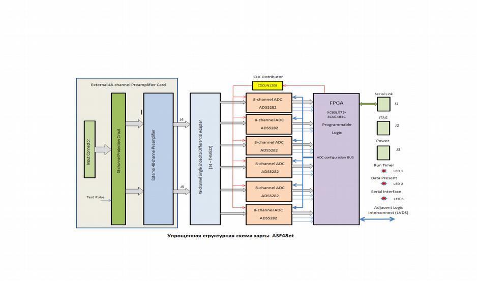
20 Fig.2 Simplified structure scheme of the ASF48et board
21 Annex 5 Calibration of the recoil proton energy scale The calibration of the TPC t-scale foreseen in this experiment relates the observed signals from TPC (S TPC ) with the absolute t-values determined from the measured θ e distributions. The calibration will be done using the whole set of collected real experimental data. For that, we select a bin S TPC in the 2D plot S TPC - θ e and look at the corresponding θ e distribution. This will be a peak at θ em with a tail to larger angles due to the energy losses of the electron before the ep collision. However, the maximum of the spectrum at θ em (with corrections for the energy losses before the ep-collision) should correspond to the undisturbed incident beam energy ε e thus allowing to determine the t- value corresponding to the selected S TPC bin. This procedure is illustrated below by MC simulation of the ep elastic scattering events at 500 MeV/c beam momentum. The beam electrons entered TPC through a 5mm Be window. Fig.1 shows the total energy of the electrons in the ep collision point at different z TPC. Fig. 1. Total energy E* of the electrons in the collision point after traversing the TPC window (0.5mm Be) and hydrogen gas ( 20 bar pressure). The initial electron momentum 500 MeV/c. One can see in these distributions well defined peaks shifted from the initial electron energy by up to 400 kev at the TPC end (Z=400 mm). 21
22 Now we can fix the energy of the recoil proton and look at the angular distribution of the scattered electrons. Fig.2 shows an example of such distribution for TR =10 MeV and z= 10 mm. Shown are two options of measuring the scattering angle. In the first option, the angle is determined by the known vertex in TPC and the X1/Y1 coordinates measured by the first CSC station. In the second option, the angle is determined independently from TPC using X1/Y1 and X2/Y2 coordinates from the CSC stations. Both options give identical result θe = mrad instead of expected θe = mrad. If one calculate the transfer momentum with this angle without correction for the electron energy loss before the collision, in this case the ratio of thus determined transfer momentum to the real transfer momentum will be 1+1.2x10⁻³. However, one can apply this correction calculated by MC. In this case the ratio becomes equal to x10-4. This result is already acceptable for the t-scale calibration. One can improve the agreement even further by taking into account the asymmetry in angular distribution of the scattered electrons caused by radiation losses. As it is shown in Fig.3, the radiation tail slightly shifts the peak value to larger angles. If we take into account this shift, then the ratio of the transfer momentum determined in this procedure to the real transfer momentum will be x10-4. One should stress again that such calibration will be done directly in the course of data analysis using the whole set of collected experimental data. Therefore, any small changes in the experiment in the parameters determining the measured recoil energy (such as signal shaping) will be automatically taken into account. Conclusion With the described method, the t-scale ( T R scale) calibration can be done with 0.02% relative precision. The cited in the proposal 0.04% precision takes also into account the systematic errors in the linear scales in the cathode planes in CSCs. Fig.2. Angular distribution of electrons scattered in TPC at z=10 mm with selected transfer momentum T R =10 MeV. MC simulation. 22
23 Fig.3. Comparision of angular distributions of scattered electrons and muons. The tail in the electron spectrum results in a mrad shift in the average angle determined in the selected θ- region. 23
Long term stability tests of INO RPC prototypes
 Long term stability tests of INO RPC prototypes While the problem of sudden aging in the glass RPC prototypes is being investigated, a few RPCs of dimension 40 cm 30 cm were fabricated, using glass procured
Performance of a triple-gem detector for high rate charged particle triggering
 Performance of a triple-gem detector for high rate charged particle triggering G. Bencivenni a,p.desimone a,f.murtas a, M. Poli Lener a1, W. Bonivento b, A. Cardini b,c.deplano b,d.pinci b,c, D. Raspino
Detecting sound wave of bubbles produced in a boiling liquid
 Detecting sound wave of bubbles produced in a boiling liquid Angela Galvez Abstract This experiment attempted to detect the sound wave produced by bubbles in boiling water and liquid nitrogen as an application
The Resistive Plate Chamber detectors at the Large Hadron Collider experiments. Danube School, September 8-13, 2014 Novi Sad
 The Resistive Plate Chamber detectors at the Large Hadron Collider experiments Roberto Guida PH-DT-DI Danube School, September 8-13, 2014 Novi Sad Ionization chambers Ionizing particles are producing primary
Design and Construction of a GEM-TPC Prototype for R&D Purposes
 Design and Construction of a GEM-TPC Prototype for R&D Purposes 2003 IEEE NSS - Satellite Workshop on Micro-Pattern Detectors for Time Projection Chambers Portland, Oregon (USA) 19-25 October, 2003 1)
Drift-Chamber Gas System Controls Development for the CEBAF Large Acceptance Spectrometer
 Drift-Chamber Gas System Controls Development for the CEBAF Large Acceptance Spectrometer M. F. Vineyard, T. J. Carroll, and M. N. Lack Department of Physics University of Richmond, VA 23173 ABSTRACT The
Analysis of RPC Performance with Different Gas Mixture
 Analysis of RPC Performance with Different Gas Mixture Cern Summer Student Programme Report Xing FAN xfan@icepp.s.u-tokyo.ac.jp 11/Sep/2015 Supervisor: Beatrice Mandelli (CERN PH-DT) 1 Introduction 1.1
The MINERνA Experiment
 The MINERνA Experiment -Brian G Tice- Rutgers, The State University of New Jersey On behalf of the MINERνA collaboration MINERνA Workshop on Electron-Nucleus Scattering XII Marciana Marina, Isola d Elba
Vacuum Simulations of the KATRIN Experiment
 Vacuum Simulations of the KATRIN Experiment Marcel Krause (KATRIN collaboration) 31.03.2014 KIT University of the State of Baden-Wuerttemberg and National Research Center of the Helmholtz Association www.kit.edu
TPC Report. D. Karlen T2K ND280m meeting December 7, 2004 Rome
 TPC Report D. Karlen T2K ND280m meeting Rome Outline Review of current TPC concept as outlined in the TPC feasibility report (December 6, 2004) http://particle.phys.uvic.ca/~karlen/t2k Performance goals
arxiv: v1 [physics.ins-det] 6 May 2016
![arxiv: v1 [physics.ins-det] 6 May 2016](/thumbs/96/129283480.jpg "arxiv: v1 [physics.ins-det] 6 May 2016") Preprint typeset in JINST style - HYPER VERSION Effect of water vapor on the performance of glass RPCs in avalanche mode operation arxiv:15.67v1 [physics.ins-det] 6 May 16 K. Raveendrababu a,d, P. K. Behera
Preprint typeset in JINST style - HYPER VERSION Effect of water vapor on the performance of glass RPCs in avalanche mode operation arxiv:15.67v1 [physics.ins-det] 6 May 16 K. Raveendrababu a,d, P. K. Behera
RPC CHARACTERIZATION AND TESTING ( by S. Mathimalar, INO Student)
") RPC CHARACTERIZATION AND TESTING ( by S. Mathimalar, INO Student) Introduction: RPC are the Resistive Plate Chamber which consists of gas mixture in the gap between two glass plates (coated with pigment
RPC CHARACTERIZATION AND TESTING ( by S. Mathimalar, INO Student) Introduction: RPC are the Resistive Plate Chamber which consists of gas mixture in the gap between two glass plates (coated with pigment
On the possibilities for the readout of gas scintillation detectors for neutron scattering applications
 On the possibilities for the readout of gas scintillation detectors for neutron scattering applications G. Manzin Institut Laue Langevin, 6 rue Jules Horowitz, 38042 Grenoble, France Abstract A gaseous
Yoke Instrumentation: ILD Muon System / Tail Catcher. Valeri Saveliev IAM, RAS, Russia DESY, Germany 3 June, 2016
 Yoke Instrumentation: ILD Muon System / Tail Catcher Valeri Saveliev IAM, RAS, Russia DESY, Germany 3 June, 2016 ILD Muon System/Tail Catcher µ - µ + Events/0.2 [GeV] 150 + Zh µ µ - X 100 50 s = 250 GeV
AC : MEASUREMENT OF HYDROGEN IN HELIUM FLOW
 AC 2010-2145: MEASUREMENT OF HYDROGEN IN HELIUM FLOW Randy Buchanan, University of Southern Mississippi Christopher Winstead, University of Southern Mississippi Anton Netchaev, University of Southern Mississippi
arxiv: v1 [hep-ex] 18 Sep 2012
![arxiv: v1 [hep-ex] 18 Sep 2012](/thumbs/93/112954019.jpg "arxiv: v1 [hep-ex] 18 Sep 2012") Preprint typeset in JINST style - HYPER VERSION arxiv:109.3893v1 [hep-ex] 18 Sep 01 Performance of the Gas Gain Monitoring system of the CMS RPC muon detector and effective working point fine tuning S.
Preprint typeset in JINST style - HYPER VERSION arxiv:109.3893v1 [hep-ex] 18 Sep 01 Performance of the Gas Gain Monitoring system of the CMS RPC muon detector and effective working point fine tuning S.
Gases&Technology. Measurement of Impurities in Helium Using the Dielectric Barrier Discharge Helium Ionization Detector. FEATURE.
 Gases&Technology FEATURE Measurement of Impurities in Helium Using the Dielectric Barrier Discharge Helium Ionization Detector. B Y M A T T H E W M O N A G L E Abstract Bulk gases are often delivered to
ARTICLE IN PRESS. Nuclear Instruments and Methods in Physics Research A
 Nuclear Instruments and Methods in Physics Research A 602 (2009) 845 849 Contents lists available at ScienceDirect Nuclear Instruments and Methods in Physics Research A journal homepage: www.elsevier.com/locate/nima
Development of small, easy to build and low gas consumming timing RPCs
 Development of small, easy to build and low gas consumming timing RPCs LabCAF/Univ. de Santiago de Compostela, Spain. E-mail: miguel.morales@usc.es J.L. Rodríguez-Sánchez Department of Particle Phisics/Univ.
This test shall be carried out on all vehicles equipped with open type traction batteries.
 5.4. Determination of hydrogen emissions page 1 RESS-6-15 5.4.1. This test shall be carried out on all vehicles equipped with open type traction batteries. 5.4.2. The test shall be conducted following
Effects of the electric field on the electron drift velocity in a double-gem detector in different gas mixtures
 Radiation Measurements 9 () 9 www.elsevier.com/locate/radmeas Effects of the electric field on the electron drift velocity in a double-gem detector in different gas mixtures P.R.B. Marinho a,, G.P. Guedes
Relative Dosimetry. Photons
 Relative Dosimetry Photons What you need to measure! Required Data (Photon) Central Axis Percent Depth Dose Tissue Maximum Ratio Scatter Maximum Ratio Output Factors S c & S cp! S p Beam profiles Wedge
EXPERIMENTAL RESULTS OF GUIDED WAVE TRAVEL TIME TOMOGRAPHY
 18 th World Conference on Non destructive Testing, 16-20 April 2012, Durban, South Africa EXPERIMENTAL RESULTS OF GUIDED WAVE TRAVEL TIME TOMOGRAPHY Arno VOLKER 1 and Hendrik VOS 1 TNO, Stieltjesweg 1,
Laser-Induced Bubbles in Glycerol-Water Mixtures
 Laser-Induced Bubbles in Glycerol-Water Mixtures Allison R. McCarn, Erin M. Englert, and Gary A. Williams Department of Physics and Astronomy, University of California, Los Angeles, California 90095, USA
A Study of Spatial Resolution of GEM TPC with Ar-CF 4 -ic 4 H 10 Gas Mixtures
 A Study of Spatial Resolution of GEM TPC with Ar-CF 4 -ic 4 H 10 Gas Mixtures H.Kuroiwa 1, K.Fujii 1, M.Kobayashi 1, T.Matsuda 1, R.Yonamine 1, A.Aoza 2, T.Higashi 2, A.Ishikawa 2, A.Sugiyama 2, H.Tsuji
Technical Specifications of Hydrogen Isotope Handling and Recovery System
 SECTION - C TECHNICAL SPECIFICATIONS OF STORES AND DRAWINGS. Technical Specifications of Hydrogen Isotope Handling and Recovery System INSTITUTE FOR PLASMA RESEARCH GANDHINAGAR, GUJARAT 382428 ANNEXURE-I
DEVICES FOR FIELD DETERMINATION OF WATER VAPOR IN NATURAL GAS Betsy Murphy MNM Enterprises 801 N. Riverside Drive Fort Worth, Texas 76111
 INTRODUCTION Water vapor in natural gas has more than a substantial effect on the quality of the gas stream. Without quality measurement of water vapor the gas is basically not saleable. Contracts are
A NOVEL SENSOR USING REMOTE PLASMA EMISSION SPECTROSCOPY FOR MONITORING AND CONTROL OF VACUUM WEB COATING PROCESSES
 A NOVEL SENSOR USING REMOTE PLASMA EMISSION SPECTROSCOPY FOR MONITORING AND CONTROL OF VACUUM WEB COATING PROCESSES F. Papa 1, J. Brindley 2, T. Williams 2, B. Daniel 2, V. Bellido-Gonzalez 2, Dermot Monaghan
780S Ultra High Purity Series
 Smart Ultra High Purity Thermal Gas Mass Flow Meter Features Measures mass flow directly, no seperate temperature or pressure inputs required Field adjustment of critical flow meter settings via on-board
A Longterm Aging Study of the Honeycomb Drift Tubes of HERA-B Using a Circulated and Purified CF -Gas Mixture
 A Longterm Aging Study of the Honeycomb Drift Tubes of HERA-B Using a Circulated and Purified CF -Gas Mixture 4 M. Capeáns, K. Dehmelt, M. Hohlmann, B. Schmidt a c b b c a CERN (Geneva) b DESY (Hamburg)
Marc McMullen. Physics Detector Support Group
 Marc McMullen Physics Detector Support Group Hall B Gaseous Detectors 1. Drift Chamber (DC) 2. Low Threshold Cherenkov Counter (LTCC) 3. High Threshold Cherenkov Counter (HTCC) 4. Silicon Vertex Tracker
Gas Leak Measurement of TRT Barrel Module
 DUKHEP01-07-02 Gas Leak Measurement of TRT Barrel Module Shannon Watson, Seog Oh Department of Physics Duke University Durham, NC, 27708, USA 1. Introduction One of the requirements for the TRT module
SiPM readout experience and prospects
 SiPM readout experience and prospects Felix Sefkow DESY CALICE collaboration ALCPG workshop at Snowmass August 23, 2005 This talk SiPM mass production and tests Experience with multi-channel readout Future
Vibration Analysis and Test of Backup Roll in Temper Mill
 Sensors & Transducers 2013 by IFSA http://www.sensorsportal.com Vibration Analysis and Test of Backup Roll in Temper Mill Yuanmin Xie College of Machinery and Automation, Wuhan University of Science and
BEST KNOWN METHODS. Transpector XPR3 Gas Analysis System. 1 of 6 DESCRIPTION XPR3 APPLICATIONS PHYSICAL INSTALLATION
 BEST KNOWN METHODS Transpector XPR3 Gas Analysis System DESCRIPTION The Transpector XPR3 is a third-generation, quadrupole-based residual gas analyzer that operates at PVD process pressures and is the
ATLAS RPC QA results at INFN Lecce
 ATLAS RPC QA results at INFN Lecce M. Bianco,, I. Borjanovic, G. Cataldi, A. Cazzato,, G. Chiodini, M.R. Coluccia,, P. Creti, E. Gorini,, F. Grancagnolo, R. Perrino, M. Primavera, S. Spagnolo,, G. Tassielli,,
Gas System Status Report
 Gas System Status Report UGPS qualification Rome Control Electronics production schedule Gas circuit testing Software commands and safety Report from MIT B. Borgia TIM April 2006 Gas Circuit B. Borgia
The Royal Australian and New Zealand College of Radiologists. FRANZCR Examination Part I Radiation Oncology. Radiotherapeutic Physics.
 FRANZCR Examination Part I Radiation Oncology Radiotherapeutic Physics Candidate No.: The Royal Australian and New Zealand College of Radiologists FRANZCR Examination Part I Radiation Oncology Radiotherapeutic
Additives that prevent or reverse cathode aging in drift chambers with Helium-Isobutane gas *
 Computer Physics Communications 1 Computer Physics Communications Additives that prevent or reverse cathode aging in drift chambers with Helium-Isobutane gas * A. M. Boyarski Stanford Linear Accelerator
A high-sensitivity large volume cryogenic detector for radon in gas
 DOI: 10.1007/s10967-008-0730-7 Journal of Radioanalytical and Nuclear Chemistry, Vol. 277, No.1 (2008) 199 205 A high-sensitivity large volume cryogenic detector for radon in gas M. Wojcik, 1 * G. Zuzel
Badan Jadrowych Nuclear Research Institute. Report INR No. 739/XIX/D CERN LIBRARIES, GENEVA CM-P Differential Recombination Chamber
 Badan Jadrowych Nuclear Research Institute Report INR No. 739/XIX/D CERN LIBRARIES, GENEVA CM-P00100517 Differential Recombination Chamber by M. Zel'chinskij K. Zharnovetskij Warsaw, June 1966 Translated
Review of the Hall B Gas System Hardware. George Jacobs
 of the Hardware George Jacobs DSG Staff 2 Hall B Gas Utilities for detectors Drift Chamber (DC) Low Threshold Cherenkov Counter (LTCC) Micromegas Vertex Tracker (MVT) Forward Tagger (FT) Ring Imaging Cherenkov
Procedure of Xenon Transfer
 Procedure of Xenon Transfer Feng Zhou,MIT CC: Martina Green February 28, 2005 In this write up, we discuss the procedure on how to transfer xenon to a designed gas storage vessel that supplies xenon to
The Transition Radiation Detector of the AMS-02 Experiment
 The Transition Radiation Detector of the AMS-02 Experiment Simonetta Gentile Università di Roma La Sapienza, INFN (Italy) for: RWTH Aachen, MIT, KNU Daegu, IEKP Karlsruhe, Universita La Sapienza, & INFN
GIF++ A New Gamma Irradiation Facility
 EDMS No. Rev Validity 1280118 0.6 REFERENCE GIF++ Project 2013-01 CERN CH-1211 Geneve 23, Switzerland Date: 26/04/13 REQUIREMENTS GIF++ A New Gamma Irradiation Facility Abstract GIF++ (Gamma Irradiation
arxiv: v1 [physics.ins-det] 16 Aug 2014
![arxiv: v1 [physics.ins-det] 16 Aug 2014](/thumbs/90/101993511.jpg "arxiv: v1 [physics.ins-det] 16 Aug 2014") Preprint typeset in JINST style - HYPER VERSION RPC Gap Production and Performance for CMS RE4 Upgrade arxiv:1408.3720v1 [physics.ins-det] 16 Aug 2014 Sung Keun Park, Min Ho Kang and Kyong Sei Lee Korea
Preprint typeset in JINST style - HYPER VERSION RPC Gap Production and Performance for CMS RE4 Upgrade arxiv:1408.3720v1 [physics.ins-det] 16 Aug 2014 Sung Keun Park, Min Ho Kang and Kyong Sei Lee Korea
Introductory Lab: Vacuum Methods
 Introductory Lab: Vacuum Methods Experiments in Modern Physics (P451) In this lab you will become familiar with the various components of the lab vacuum system. There are many books on this topic one of
ADDENDUM IMPORTANT DOCUMENT INVITATION TO BID ADDENDUM. OPENING DATE & TIME: January 3, 2018 at 3:00PM
 Procurement Services ADDENDUM IMPORTANT DOCUMENT INVITATION TO BID ADDENDUM ITB NUMBER: 1708MC OPENING DATE & TIME: January 3, 2018 at 3:00PM ITB TITLE: X-Ray Photoelectron Spectroscopy System ADDENDUM
HumiSys HF High Flow RH Generator
 HumiSys HF High Flow RH Generator Designed, built, and supported by InstruQuest Inc. Versatile Relative Humidity Generation and Multi-Sensor System The HumiSys HF is a high flow version of the previously
Vacuum System at IUAC
 Vacuum System at IUAC A. Mandal Inter-University Accelerator Centre, Aruna Asaf Ali Marg, Post Box - 10502, New Delhi 110067, Fax:011-26893666. email: mandal@iuac.res.in Abstract: Vacuum technology is
Jefferson Lab Bubble Chamber Experiment Update and Future Plans. C(a,g) 16 O. Claudio Ugalde
 16 O. Claudio Ugalde") Jefferson Lab Bubble Chamber Experiment Update and Future Plans 12 C(a,g) 16 O Claudio Ugalde Collaboration Whitney Armstrong Melina Avila Kevin Bailey Tom O Connor Ernst Rehm Seamus Riordan Brad DiGiovine
Jefferson Lab Bubble Chamber Experiment Update and Future Plans 12 C(a,g) 16 O Claudio Ugalde Collaboration Whitney Armstrong Melina Avila Kevin Bailey Tom O Connor Ernst Rehm Seamus Riordan Brad DiGiovine
Preliminary results of Resistive Plate Chambers operated with eco-friendly gas mixtures for application in the CMS experiment
 Prepared for submission to JINST 13 th workshop on resistive plate chambers and related detectors 22-26 february 2016 ghent university, belgium Preliminary results of Resistive Plate Chambers operated
THE development of more advanced techniques in radiotherapy,
 1 A Geant4-based simulation of an accelerator s head used for Intensity Modulated Radiation Therapy F. Foppiano, B. Mascialino, M.G. Pia, M. Piergentili. Abstract We present a Geant4-based simulation,
The Gas Attenuator of FLASH
 INTRODUCTION The Gas Attenuator of FLASH K. Tiedtke, N. von Bargen, M. Hesse, U. Jastrow, U. Hahn The experimental hall of the FLASH user facility is located approximately 30m behind the last dipole magnet
Technical Data Sheet MF010-O-LC
 Technical Data Sheet MF010-O-LC - 1 - 1. Properties The oxygen measuring system MF010-O-LC determines the oxygen content in gas mixtures up to a temperature of 250 C. It is particularly suitable for the
Irrigation &Hydraulics Department lb / ft to kg/lit.
 CAIRO UNIVERSITY FLUID MECHANICS Faculty of Engineering nd Year CIVIL ENG. Irrigation &Hydraulics Department 010-011 1. FLUID PROPERTIES 1. Identify the dimensions and units for the following engineering
Experience with the ZEUS central tracking detector
 Computer Physics Communications 1 Computer Physics Communications Experience with the ZEUS central tracking detector David Bailey, a, * Richard Hall-Wilton b a H.H.Wills Physics Laboratory, Tyndall Avenue,
ETCHING OF COPPER COATED MYLAR TUBES WITH CF4 GAS. Karl M. Ecklund, Keith W. Hartman, Michael J. Hebert, Stanley G. Wojcicki
 SLAC-PUB-16219 ICFA INSTRUMENTATION B ULLETIN ETCHING OF COPPER COATED MYLAR TUBES WITH CF4 GAS Karl M. Ecklund, Keith W. Hartman, Michael J. Hebert, Stanley G. Wojcicki Department of Physics, Stanford
ELEVATION CORRECTION FACTORS FOR RADON MONITORS*
 ELEVATION CORRECTION FACTORS FOR E-PERM@ RADON MONITORS* P. Kotrappa and L. R. Stiefl Abstract-E-PERMm radon monitors are based on the principle of electret ion chambers and are usually calibrated in a
Exradin Ion Chambers. What attributes make Exradin the smart choice? EXRADIN Ion Chambers
 EXRADIN Ion Chambers Exradin Ion Chambers Exradin (EXacting RADiation INstrumentation) Ion Chambers have been built for over 33 years, are recognized by top research institutes and standards laboratories,
Practical approach and problems in in-situ RGA calibration
 Practical approach and problems in in-situ RGA calibration Oleg Malyshev and Keith Middleman Vacuum Science Group, ASTeC Accelerator Science and Technology Centre STFC Daresbury Laboratory UK Workshop
FPG8601 Force Balanced Piston Gauge
 FPG8601 Force Balanced Piston Gauge Reference Level Calibration System for very low pressure Pressure range: 0 to 15 kpa gauge, absolute and absolute differential Standard resolution: 0.010 Pa, high resolution
Proudly serving laboratories worldwide since 1979 CALL for Refurbished & Certified Lab Equipment Varian 310
 www.ietltd.com Proudly serving laboratories worldwide since 1979 CALL +847.913.0777 for Refurbished & Certified Lab Equipment Varian 310 310 LC/MS Manual System INCLUDES: 310-MS LC/MS triple quadrople
Acoustic Emission Testing of The Shell 0f Electromagnetic Valve
 17th World Conference on Nondestructive Testing, 25-28 Oct 2008, Shanghai, China Acoustic Emission Testing of The Shell 0f Electromagnetic Valve guozhen XU 1, yiwei CHEN 1, zhihua CAO 2 ABSTRACT Shanghai
CHAPTER 4 PRE TREATMENT PATIENT SPECIFIC QUALITY ASSURANCE OF RAPIDARC PLANS
 47 CHAPTER 4 PRE TREATMENT PATIENT SPECIFIC QUALITY ASSURANCE OF RAPIDARC PLANS 4.1 INTRODUCTION Advanced treatment techniques use optimized radiation beam intensities to conform dose distribution to the
Assembly and measurements of a mechanical prototype of the BIS MDT chamber
 ATLAS Internal Note MUON NO 243 9 June 1998 Assembly and measurements of a mechanical prototype of the BIS MDT chamber K. Ekonomou Physics Department, Aristotle University of Thessaloniki, Thessaloniki,
The Estimation Of Compressor Performance Using A Theoretical Analysis Of The Gas Flow Through the Muffler Combined With Valve Motion
 Purdue University Purdue e-pubs International Compressor Engineering Conference School of Mechanical Engineering The Estimation Of Compressor Performance Using A Theoretical Analysis Of The Gas Flow Through
7250 Sys. Ruska Multi-Range Pressure Calibration System. GE Sensing & Inspection Technologies. Features. Applications
 GE Sensing & Inspection Technologies 7250 Sys Ruska Multi-Range Pressure Calibration System Features Fully integrated multi-range pressure test and calibration systems Select either an eight range or the
Choosing a Quadrupole Gas Analyzer Application Note #9
 Choosing a Quadrupole Gas Analyzer Application Note #9 Modern-day contamination control requirements for gas phase processes are constantly pushing the limits of performance of quadrupole gas analyzers.
Vortex Meters for Liquids, Gas, and Steam
 A Measuring Principle Comes of Age: Vortex Meters for Liquids, Gas, and Steam Dipl.-Hyd. Oliver Seifert, Product Management Vortex Meters at Flowtec AG, and Ellen-Christine Reiff, M.A., Editor s Office,
Assembly and Testing of RPCs in Pakistan. Hafeez Hoorani National Centre for Physics
 Assembly and Testing of RPCs in Pakistan Hafeez Hoorani National Centre for Physics 1 Layout Introduction RPCs in CMS RPC: From Lab to Detector Assembly Testing QA & QC Installation and Commissioning 2
Cover Page for Lab Report Group Portion. Pump Performance
 Cover Page for Lab Report Group Portion Pump Performance Prepared by Professor J. M. Cimbala, Penn State University Latest revision: 02 March 2012 Name 1: Name 2: Name 3: [Name 4: ] Date: Section number:
LINEAR TRANSFORMATION APPLIED TO THE CALIBRATION OF ANALYTES IN VARIOUS MATRICES USING A TOTAL HYDROCARBON (THC) ANALYZER
 ANALYZER") LINEAR TRANSFORMATION APPLIED TO THE CALIBRATION OF ANALYTES IN VARIOUS MATRICES USING A TOTAL HYDROCARBON (THC) ANALYZER Michael T Tang, Ph.D. Grace Feng Greg Merideth Rui Huang Matheson Gas Applied Lab
LINEAR TRANSFORMATION APPLIED TO THE CALIBRATION OF ANALYTES IN VARIOUS MATRICES USING A TOTAL HYDROCARBON (THC) ANALYZER Michael T Tang, Ph.D. Grace Feng Greg Merideth Rui Huang Matheson Gas Applied Lab
UK Opportunities in SiD Calorimetry
 UK Opportunities in SiD Calorimetry Paul Dauncey Imperial College London 7 Sept 2007 Paul Dauncey - Calorimetry 1 Overview SiD is designed for particle flow Calorimeters will be optimised using particle
Flow in a shock tube
 Flow in a shock tube April 30, 05 Summary In the lab the shock Mach number as well as the Mach number downstream the moving shock are determined for different pressure ratios between the high and low pressure
Vortex flowmeters. Product family introduction Principle of operation Product review Applications Key product features
 Vortex flowmeters introduction Product review s Key product features This document should not be duplicated, used, distributed, or disclosed for any purpose unless authorized by Siemens. Page 1 Vortex
Performance of the Liquid Hydrogen Target
 Performance of the Liquid Hydrogen Target Presented by Chad Gillis Indiana University at NPDGamma Collaboration Meeting July 2012, Oak Ridge, Tennessee Since upgrading the target for operation at the SNS,
Standard Operating Manual
 Standard Operating Manual ARC12M Sputter Copyright 11.2015 by Hong Kong University of Science & Technology. All rights reserved. Page 1 Contents 1. Picture and Location 2. Process Capabilities 2.1 Cleanliness
Guideline for RMO Key comparison for Air kerma rate in 60 Co gamma radiation
 Guideline for RMO Key comparison for Air kerma rate in 60 Co gamma radiation This intercomparison will be carried out under the lead of KRISS with the cooperation of ARPANSA. This comparison has been approved
The Helium Leak Detector
 The Helium Leak Detector Helium Leak Detector Main Components The main components of a helium leak detector are: 1. The analyzed, which enables to separate the tracer gas from other gases inside leak detector.
EUROPEAN LABORATORY FOR PARTICLE PHYSICS STUDY OF AGEING AND GAIN LIMITS OF MICROSTRIP GAS CHAMBERS AT HIGH RATES
 EUROPEAN LABORATORY FOR PARTICLE PHYSICS CERN-PPE/96-20 8 November, 996 STUDY OF AGEING AND GAIN LIMITS OF MICROSTRIP GAS CHAMBERS AT HIGH RATES B. Boimska, R. Bouclier, M. Capeáns, S. Claes 2, W. Dominik,
Analysis of Pressure Rise During Internal Arc Faults in Switchgear
 Analysis of Pressure Rise During Internal Arc Faults in Switchgear ASANUMA, Gaku ONCHI, Toshiyuki TOYAMA, Kentaro ABSTRACT Switchgear include devices that play an important role in operations such as electric
Paper 2.2. Operation of Ultrasonic Flow Meters at Conditions Different Than Their Calibration
 Paper 2.2 Operation of Ultrasonic Flow Meters at Conditions Different Than Their Calibration Mr William Freund, Daniel Measurement and Control Mr Klaus Zanker, Daniel Measurement and Control Mr Dale Goodson,
MACH ONE MASS FLOW CONTROLLER. MACH ONE SERIES flow control. MASS FLOW CONTROLLERS at the speed of sound.
 MACH ONE MASS FLOW CONTROLLER MACH ONE SERIES flow control MASS FLOW CONTROLLERS at the speed of sound. MACH ONE SERIES MASS FLOW CONTROLLER FLOW CONTROL AT THE SPEED OF SOUND The Mach One revolutionary
Ion-atom interactions in a gas jet - coupling of a gas catcher to a linear RFQ cooler
 Ion-atom interactions in a gas jet - coupling of a gas catcher to a linear RFQ cooler Emil Traykov, IPHC, SIMION Day, GANIL 11/06/2015 Several existent add-on models allow the inclusion of a gas-ion interaction
ITTC Recommended Procedures and Guidelines
 Page 1 of 6 Table of Contents 1. PURPOSE...2 2. PARAMETERS...2 2.1 General Considerations...2 3 DESCRIPTION OF PROCEDURE...2 3.1 Model Design and Construction...2 3.2 Measurements...3 3.5 Execution of
Pressure & Vacuum Measurement. Series 370. Solutions. Stabil-Ion Vacuum gauge and Controller
 w w w. m k s i n s t. c o m Pressure & Vacuum Measurement Solutions Series 370 Stabil-Ion Vacuum gauge and Controller Features & Benefits All-metal, rack-mount controller for Stabil-Ion and Convectron
Using PV Diagram Synchronized With the Valve Functioning to Increase the Efficiency on the Reciprocating Hermetic Compressors
 Purdue University Purdue e-pubs International Compressor Engineering Conference School of Mechanical Engineering 21 Using PV Diagram Synchronized With the Valve Functioning to Increase the Efficiency on
The Principles of Vacuum Technology
 The Principles of Vacuum Technology Vacuum Terminology Vacuum units Vacuum regimes How to measure vacuum. Gauge designs. How to create vacuum Pump classifications and designs UHV compatibility considerations
PIG MOTION AND DYNAMICS IN COMPLEX GAS NETWORKS. Dr Aidan O Donoghue, Pipeline Research Limited, Glasgow
 PIG MOTION AND DYNAMICS IN COMPLEX GAS NETWORKS Dr Aidan O Donoghue, Pipeline Research Limited, Glasgow A model to examine pigging and inspection of gas networks with multiple pipelines, connections and
SUPERSONIC GAS TECHNOLOGIES
 SUPERSONIC GAS TECHNOLOGIES Vladimir Feygin, Salavat Imayev, Vadim Alfyorov, Lev Bagirov, Leonard Dmitriev, John Lacey TransLang Technologies Ltd., Calgary, Canada 1. INTRODUCTION The 3S technology is
Measuring mass flows in hermetically sealed MEMs & MOEMs to ensure device reliability
 Measuring mass flows in hermetically sealed MEMs & MOEMs to ensure device reliability R. C. Kullberg*, D. J. Rossiter** Oneida Research Services, Inc., 8282 Halsey Road, Whitesboro, NY13492 Abstract Many
MODEL GT820 OXYGEN SENSOR
 INSTRUCTION MANUAL MODEL GT820 OXYGEN SENSOR 70046 The information and technical data disclosed by this document may be used and disseminated only for the purposes and to the extent specifically authorized
INSTRUMENTS A THERMAL MASS FLOW SENSOR USING A CONSTANT DIFFERENTIAL TEMPERATURE ABOVE THE AMBIENT GAS TEMPERATURE
 TELEDYNE HASTINGS TECHNICAL PAPERS INSTRUMENTS A THERMAL MASS FLOW SENSOR USING A CONSTANT DIFFERENTIAL TEMPERATURE ABOVE THE AMBIENT GAS TEMPERATURE Proceedings of FEDSM 98 1998 ASME Fluids Engineering
The TOTEM Gas System
 Total Cross Section, Elastic Scattering and Diffraction Dissociation at the LHC EDMS No.: TOTEM-DI-ER-0001 TOTEM Experiment document No.: IN-2000/02 The TOTEM Gas System M. Bozzo (1), M. Castoldi (2),
A variable-pressure constant-volume method was employed to determine the gas permeation
 Electronic Supplementary Material (ESI) for RSC Advances. This journal is The Royal Society of Chemistry 2015 S.1. Gas permeation experiments A variable-pressure constant-volume method was employed to
Plasma. Argon Production Helium Liquefaction Truck Loading Pure Gas Bottling
 SERVOPRO Plasma The SERVOPRO Plasma is a Plasma Emission Detector based analyser designed to continuously measure Nitrogen in pure Argon for process and quality control in Argon production within Cryogenic
Integral type Differential pressure flowmeter VNT Series
 Integral type Differential pressure flowmeter VNT Series OUTLINE VH series Wafer-Cone differential pressure flowmeter and high precision differential pressure transmitter are integrated into one flowmeter.
Detector Carrier Gas Comments Detector anode purge or reference gas. Electron Capture Nitrogen Maximum sensitivity Nitrogen Argon/Methane
 Gas requirements Gases for packed columns The carrier gas you use depends upon the type of detector and the performance requirements. Table 520-1 lists gas recommendations for packed column use. In general,
Title: Standard Operating Procedure for Measurement of Ethylene (C 2 H 4 ) in Ambient Air by Reduced Gas Detection (RGD)
 in Ambient Air by Reduced Gas Detection (RGD)") Procedure No: SOP-026 Revision No: 1.0 January 24, 2011 Page No.: 1 of 10 1. INTRODUCTION AND SCOPE To obtain timely data for the purpose of air quality assessment, air quality trend reporting and to meet
Procedure No: SOP-026 Revision No: 1.0 January 24, 2011 Page No.: 1 of 10 1. INTRODUCTION AND SCOPE To obtain timely data for the purpose of air quality assessment, air quality trend reporting and to meet