1. Welcome to systec Controls. 2. Table of Contents
|
|
|
- Valentine Cook
- 5 years ago
- Views:
Transcription
1 Installation Guide 1
2 1. Welcome to systec Controls Congratulations on your purchase of a deltaflow dynamic pressure probe, a highly precise measurement tool of superior quality which delivers the best possible results under even the most challenging conditions. In order to take the very best advantage of these qualities, it is important that you install and connect your deltaflow properly. If it is installed incorrectly, even the best tool on the market cannot operate to its full potential. Please read the Installation and Maintenance Guide carefully and call on our support staff for assistance if any questions arise. We will be more than happy to review your installation requirements and advise you regarding where and how to install your deltaflow for the best possible results. 2. Table of Contents 1. Welcome to systec Controls Table of Contents Selecting an Appropriate Sampling Site Weld-In Stud Orientation Gaseous Media Liquid Media Steam Media Installing the Weld-in Stud Installing the Opposite support Installing Pulse Conduits / Connecting the Differential Pressure Transducer Steam Media Liquid Media Gas Media Splitting Range, Bi-directional, or Redundant Multiple Transmitters for the deltaflow Zero Point Calibration at Differential Pressure Transducer after Installation Zero Point Calibration for Gas Media Zero Point Calibration for Liquid and Steam Media Additional Tips for Installing the DF25-Quicklock Additional Tips for Installing the DF8 / DF10 or DF12/DF25 with spool pieces Additional Tips for Using the LSP1 Air Flushing System Integrated Pressure and Temperature Sensors Iceproofing / Weatherproof Housing Maintenance Troubleshooting Additional Information Questions? Flow meters made by systec...16 Required qualifications of installation / maintenance staff The installation, commissioning and maintenance of this product have to be done by qualified personel which has been accepted by the plant operator. The qualified personal has to read and to understand this manual. Before using deltaflow in corrosive and/or abrasive media the resistance of the material of deltaflow and it s components has to be proven by the user or the plant operator. Systec Controls offers assistance by choosing proper materials but can not assume liability. The user or plant operator has to follow his national regulations for installation, commissioning, service and maintenance. Liability regulations systec Controls does not assume liability if deltaflow is not used fort he intended purpose or if this manual has not been respected or if unqualified personel have done the required work or if deltaflow or one of its components has changed without written agreement of systec Controls. The liability will expire in that case. 2
3 3. Selecting an Appropriate Sampling Site To reach the optimum degree of precision, the deltaflow needs to be allowed the inlet and outlet path lengths outlined in the table below. The values in the gray shaded fields apply if ImproveIT is used to calculate the adjustment of the measurement values. The fields surrounded by double lines display the standard values. Installation Position Anticipated Precision Without ImproveIT Adjustment With ImproveIT Adjustment Level Inlet A Outlet B Inlet A Outlet B 0.5% 14 x DI 3 x DI 7 x DI 3 x DI A B 1.0% 7 x DI 3 x DI 4 x ID 3 x ID 2.0 % 4 x DI 2 x DI 1 x DI 2 x DI 0.5% 18 x DI 3 X DI 7 x DI 3 x DI A A B B 1.0% 9 x DI 2 x DI 4 x ID 3 x ID 2.0 % 5 x DI 2 x DI 2 x DI 1 x DI 0.5% 14 x DI 3 x DI 1.0% 7 x DI 3 x DI 2.0 % 4 x DI 2 x DI 0.5% 14 x DI 3 x DI 1.0% 7 x DI 3 x DI A B 2.0 % 4 x DI 2 x DI 0.5% 36 x DI 6 x DI 1.0% 24 x DI 4 x DI A B 2.0 % 12 x Di 3 x DI 0.5% 24 x DI 6 X DI 12 x DI 3 x DI A B 1.0% 17 x DI 4 x DI 7 x D 3 x D 2.0 % 9 x DI 3 x DI 2 x DI 2 X DI 3

 toward the point of the probe.")
4 4. Weld-In Stud Orientation You must select the appropriate orientation for your stud based on the media, the conduit, and the model design of your deltaflow Gaseous Media Installation Position Vertical conduit, connection head at right angle Horizontal conduit, connection head at right angle Horizontal conduit, straight connection head. Illustration Comment The stud is installed in a horizontal position or with a slight decline (maximum 3 ) toward the point of the probe. Leads to the differential pressure transducer are trailed upwards. This ensures that any condensation can run off without obstruction. The stud is installed in a horizontal position or with a slight decline (maximum 3 ) toward the point of the probe. Leads to the differential pressure transducer are trailed upwards. This ensures that any condensation can run off without obstruction. The probe is installed vertically from either the top or the bottom of the conduit, or at an angle of a maximum of +/- 30. Leads to the differential pressure transducer are trailed upwards. This ensures that any condensation can run off without obstruction Liquid Media Installation Position Vertical conduit, connection head at right angle Horizontal conduit, connection head at right angle Horizontal conduit, straight connection head. Illustration Comment The stud is installed in a horizontal position or with a slight incline (maximum 3 ) toward the point of the probe. Leads to the differential pressure transducer are trailed downwards. This ensures that the deltaflow can be ventilated with no difficulties. The stud is installed in a horizontal position or with a slight incline (maximum 3 ) toward the point of the probe. Leads to the differential pressure transducer are trailed downwards. This ensures that the deltaflow can be ventilated properly. The probe is installed upside down, or at an angle of a maximum of +/- 30. The leads to the differential pressure transducer are trailed downwards. Gas bubbles can escape from the deltaflow without obstruction Steam Media Installation Position Horizontal Conduit Vertical Conduit Illustration Comment The probe is installed horizontally or with a slight decline (max. 3 ) toward the point of the probe. The leads to the dp transducer are trailed downwards. Excess condensation flows back into the conduit and evaporates there. When installing, it is very important to make sure that the condensation containers are aligned and level (use a spirit level)! The probe is installed horizontally or with a slight decline (maximum 3 ) toward the point of the probe. The leads to the transducer are trailed downwards. Excess condensation flows back into the conduit and evaporates there. When installing, it is very important to make sure that the condensation containers are aligned and perfectly level (use a spirit level)! 4

5 5. Installing the Weld-in Stud Your deltaflow purchase comes complete with an appropriate weld-in stud. The dimensions of the weld-in stud have a significant impact on metering precision. Please use the stud that came with your deltaflow and please do not alter the stud in any way! The standard height of the weld-in stud is 125 mm. For installations where insulation thicknesses are >100mm, special probes with extended studs are provided by systec. Please contact systec if there is any question regarding this equipment. Cutting Ring Stud The standard height of the cutting ring stud h1 (without swivel nut) is 125mm, h2 (with swivel nut, after tightening approx. 137mm). Other stud heights are available from systec. Flange Stud The standard height of the flange stud h is 125 mm. Other stud heights are available from systec. To install the weld-in stud, please determine and mark the installation point, then bore a 28 mm hole (for deltaflow model DF25) or a 53.5mm hole (DF44) or a 60 mm hole (DF50) into the conduit. For DF12 see separate chapter 12. If your deltaflow includes an opposite support, determine the positioning of the opposite support and bore another hole into the opposite wall of the conduit. Directions for determining the position of the opposite support can be found below, under Item 6. Flange holes for the weld-in stud must be positioned parallel to the direction of the conduit. Remove all paint and rust in the area surrounding the welding site and select a welding filler appropriate to the material of the stud and the conduit material. The welding fillers recommended below are not mandatory. Please confirm your choice of an appropriate welding filler with your welding expert, or contact systec Controls. Recommended Welding Fillers (Böhler) Conduit Material Stud Material WIG Electrodes Oxyacetylene Carbon Steel (St 35.8) Carbon Steel (ST35.8) DMO-IG Fox EV50 BW XII Carbon Steel (St 35.8) Stainless Steel (1.4571) A7-A-IG Fox A7-A-IG - Stainless Steel (1.4571) Stainless Steel (1.4571) SAS4-IG Fox SAS4-IG - You will find a stamp imprinted on the stud identifying the material the stud is made of, or the material will be indicated in the sales confirmation. If you are unsure about the material of the stud, the conduit, or the welding filler, please consult your welding expert or contact us. Tack-weld the weld-in stud to this location and adjust it carefully, considering the correct installation orientation and recommended slope. To be sure that the stud is positioned correctly, it is a good idea to temporarily install the probe into the stud once the stud has been tack-welded to the conduit. Please be sure to remove the probe before you finish welding the stud. The probe should extend all the way through the diameter of the conduit, and may even touch the opposite wall of the pipe (this is not true if an opposite support is being installed). If the probe is too short or too long, please re-measure the conduit (exterior diameter and wall thickness) and the stud (length), note the probe s serial number (DF...) and contact your sales agent or systec Controls directly before proceeding to install the equipment. Use a brush to remove any punk or tarnish, and take appropriate steps to protect both stud and conduit from rust. 5


6 6. Installing the Opposite support Some deltaflow models are equipped with opposite supports; opposite supports are standard on DN 1000 and larger. The opposite support is an integral part of the product and must not be altered. Standard opposite support for deltaflow DF25: In addition to the standard opposite support, there are several other optional designs. If you are not sure, note the serial number of your deltaflow and contact your agent or directly systec Controls. One way to determine the point on the conduit opposite the stud is to use a piece of writing paper. Without folding, wrap the paper around the pipe and position the overlap of the two edges at the center of the weld-in stud. Use a pencil to mark the point of overlap on the paper. Remove the paper from the pipe and fold the marked length (circumference) in half. Mark this halfway point as well. Put the paper back to the pipe in the previous position. Mark the halfway point on the conduit, where the opposite support will be installed. For the opposite support, drill a hole 28mm (for deltaflow model DF25) or 78mm (for deltaflow model DF50) in diameter into the conduit. Remove all paint and rust in around the welding points and select a welding filler material appropriate to the opposite support and the conduit. We recommend that you first tack-weld the stud into the conduit, adjust the positioning, and then temporarily install the deltaflow. Next plug the opposite support onto the deltaflow so you can be sure it is positioned correctly, and then carefully tack-weld the bearing onto the conduit. Finally, uninstall the deltaflow and weld the stud and opposite support firmly into place. Gegenlager DF25/DF34/DF44 Opposite Support D25/DF34/DF44 7. Installing Pulse Conduits / Connecting the Differential Pressure Transducer On your deltaflow you will find a label indicating the flow direction and the polarity of the differential pressure connections. Please attach the + and connections to your dp transducer as indicated on the label depending on the direction of your flow. There will be + and indicators on the transducer as well. 6
 and that the pulse conduits are installed with a steady decline toward the")

7 7.1. Steam Media The deltaflow for steam comes equipped with condensation containers. The differential pressure is carried to the transmitter via a condensate column. When installing, be sure that the condensation containers are installed in a horizontal position (use a spirit level) and that the pulse conduits are installed with a steady decline toward the transmitter. Separate Mounting If the deltaflow is purchased without installation block or three-way manifold, the impulse conduits must be installed onsite. In this situation, the differential pressure transducer is generally installed in combination with a multidirectional valve assembly on a wall or mounting frame. The impulse conduits between the deltaflow and the dp transducer must maintain a consistent downward slope and should have an interior diameter of a minimum of 8mm. The length of the impulse conduits can be determined at will, but be sure to position the conduits close to each other and parallel in order to prevent differences Direct Mounting If the deltaflow is purchased with an installation block and multi-directional valve assembly, the dp transducer can be mounted directly to the probe and no additional conduits are necessary Liquid Media When using the deltaflow for liquids, the differential pressure is carried to the dp transmitter through the liquid. Gas bubbles within the pulse conduits result in metering errors. For this reason, it is important to install and connect the dp transducer in such a way as to allow gas bubbles to rise to the conduit pipes. Separate Mounting d If the deltaflow is purchased without installation block or three-way manifold, the impulse conduits must be installed onsite. In this situation, the differential pressure transducer is generally installed in combination with a multi-directional valve assembly on a wall or mounting frame. The impulse conduits between the deltaflow and the dp transducer must maintain a consistent downward slope and should have an interior diameter of a minimum of 8mm. The length of the impulse conduits can be determined at will, but be sure to position the conduits close to each other and parallel in order to prevent differences in temperature and density between the two conduits. Direct Mounting If the deltaflow is purchased with an installation block and multi-directional valve assembly, the dp transducer can be mounted directly to the probe and no additional conduits are necessary. 7


8 7.3. Gas Media Condensates within your deltaflow can disrupt the metering of gasses. For this reason, it is important to connect the dp transducer in such a way as to allow condensation to drain freely toward the point of the probe. Separate Mounting dp If the deltaflow is purchased without installation block or three-way manifold, the impulse conduits must be installed onsite. In this situation, the differential pressure transducer is generally installed in combination with a multidirectional valve assembly on a wall or mounting frame. The impulse conduits between the deltaflow and the dp transducer must maintain a consistent upward slope and should have an interior diameter of a minimum of 8mm. The length of the impulse conduits can be determined at will. Direct Mounting dp If the deltaflow is purchased with an installation block and multi-directional valve assembly, the dp transducer can be mounted directly to the probe and no additional conduits are necessary. 8. Splitting Range, Bi-directional, or Redundant ant Multiple Transmitters for the deltaflow For specific applications such as metering flow in two directions (bi-directional), automatic split range for large flow metering ranges (Splitting Range), or multiple metering (redundant) deltaflow can be equipped with multiple transducers. This can be done using either direct mounting or separate mounting methods. For automatic splitting range and redundant metering, transducers with different sampling ranges are connected in parallel configuration. For bi-directional metering, the + and connections at the transducer need to be switched to compensate for the negative flow. Separate Mounting (Gas) Direct Mounting (Liquid) dp dp The direct mounting process can be made quick and easy by using the optional double oval flanges available from systec. With these flanges, most dp transducers can simply be attached one below the other. (The example depicts 3 model SYS4422 transducers mounted in this way.) 8
9 9. Zero Point Calibration at Differential Pressure Transducer after Installation In order to ensure the high degree of precision manifested by the deltaflow flow metering system under even the most minimal flow conditions, it is recommended that you perform a zero point calibration of the dp transducer after installation. Conditions during transportation, installation procedures, changes in temperature, and static pressure all have an influence on the zero point of your dp transducer, so it is best if you perform the zero point calibration after the conduit has been filled and when actual operational pressure is in effect. It is also possible to check the zero point calibration on the dp transducer from time to time after the initial startup, and to adjust it as needed. Manufacturers of dp transducers recommend maintenance checks every two to five years. In metering conditions involving extremely small differential pressures (i.e. when metering flue gas flows) and wide variations in ambient temperatures (i.e. outdoor applications), it might be advisable to perform these maintenance checks more frequently Zero Point Calibration for Gas Media dp close open If you have installed a three or five-way manifold between your deltaflow and your dp transducer, then close both of the process valves (outer) and then open the bypass valve (middle). This creates the physical balance between + and, and the differential pressure is zeroed out. If there is no three or five-way manifold in your setup, be sure that there is no flow present in your conduit before performing the calibration procedure. We recommend that you close off all valves leading into your conduit. If your system includes a primary shut-off, you can close it and then open both of the ventilation valves at the transmitter. Both sides of the dp transducer are thus depressurized against the ambient environment, and the differential pressure is zeroed out. Finally, perform a zero point calibration at your transmitter. You should find detailed instructions for this procedure in your transmitter documentation. On most transmitters you will find a button, a magnetic switch, or a potentiometer labeled ZERO which will allow you to perform the calibration. In some cases it may be necessary to attach an amperemeter to the outlet path of your dp transducer in order to monitor the calibration. Many dp transmitters include a display for monitoring purposes. Some models of transmitters are even equipped with a calibration mode to adjust for factors related to the installation situation as well as a separate calibration mode for the zero point. Please refer to your transmitter documentation for details Zero Point Calibration for Liquid and Steam Media If you are metering flows in liquid or in steam, you must be sure that your deltaflow is completely filled with the liquid or the condensate before performing the zero point calibration. If the deltaflow is not completely full (it is 100% ventilated=there is 0% air remaining in the meter), the zero point calibration will be flawed. To ventilate, open all shut-offs between the deltaflow and the transmitters (except the bypass). If care was taken during installation and pipe assembly to ensure that the probe was installed with a steady decline, the deltaflow will eventually ventilate itself automatically when used in a full conduit. For metering liquids, allow approximately one hour for this to happen; for steam applications, allow approximately 2 hours. If the conduit is not completely full, or if you do not want to wait so long, you can also fill the deltaflow manually. To do this, remove the ventilation screws at the dp transducers and force the medium throught the transmitters upwards into the conduit. If you have installed a three or five-way manifold between the deltaflow and the dp transducer, then close both of the process valves (outer) and open the bypass valve (center). This creates the physical balance between + and, and the differential pressure is zeroed out. If there is no three or five-way manifold in your setup, be sure that there is no flow present in your conduit before performing the calibration procedure. We recommend that you close off all valves leading into your conduit. 9

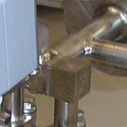
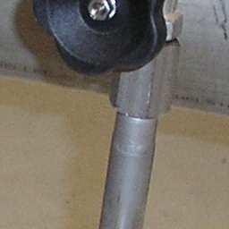
10 Finally, perform a zero point calibration at your transmitter. You should find detailed instructions for this procedure in your transmitter documentation. On most transmitters you will find a button, a magnetic switch, or a potentiometer labeled ZERO which will allow you to perform the calibration. In some cases it may be necessary to attach an amperemeter to the outlet path of your dp transducer in order to monitor the calibration. Many dp transmitters include a display for monitoring purposes. Some models of transmitters are even equipped with a calibration mode to adjust for factors related to the installation situation as well as a separate calibration mode for the zero point. Please refer to your transmitter documentation for details. 10. Additional Tips for Installing the DF25-Quicklock The DF25 Quiklock is available in two models: with flanged ball fittings or with weld-in ball fittings. For either model, the weld-in studs should be removed from the rest of the probe before installation and should be welded in separately. Please take note of the issues discussed above in the section Installing the Weld-in Stud. Detach the studs here before installing We recommend to mark the position of the extracted probe to ensure a secure operation. In case of changing the probe, the position of the extracted probe is known. That is important and makes sure that the probe is completely extracted and thus the ball valve can be unrestricted and secure shut. That is needed to prevent damages from the ball valve, probe and working process. An extracting during the regular plant operation can only be done with the situation suited protection equipment. (Protection suit, safety glasses, face shield, and so on) If the security is ensured, the sequence is as follows: 1. Loosen the sleeve, marked in the picture above with 1 2. Changing loosen of the nuts, marked in picture above with 2. In some cases the pressure in the tube pushes the probe automatically out of the tube. To prevent damages at the sleeve a cant is to be avoided. 3. As soon as the probe reached the marked position or is as far out of the tube that the ball valve can not cause damage, the ball valve can be shut. 4. After closing the ball valve the probe can be completely removed by changing loosen the nuts. See in above picture at 2. Attantion: By extracting the probe there is possibly a pressure left. Thus the medium can escape explosively on the sleeve. Sutied protective measures has to be considered. 10

11 11. Additional Tips for Installing the DF8 / DF10 or DF12/DF25 with spool pieces The DF8 and the DF10 consist of spool pieces in which the probe (or in some cases the orifice) is purchased preinstalled. DF12 and DF25 are optionally available with spool piece. The DF10 and the DF8 but also the DF12 and DF25 (available with spool pieces as an option) are available with various connection options for tying into your conduit system, such as flanges, weld-on ends, or threaded connections. The correct orientation of the probe or the orifice depends on the configuration of the dp connections and should be easy to determine visually. When determining the correct orientation of the sampling range, please follow the same instructions as were given in the section Weld-in Stud. Orientation above. It is as vital for the DF8 and the DF10 as it is for the DF12/DF25 that there is proper ventilation or the drainage of condensates. 12. Additional Tips for using DF12 (without spool piece) The deltaflow DF12 is available with spool piece (see chapter 11) as well as stand-alone probe. In that case the DF12 can be mounted using flange or cut ring stud or can be welded into the pipe directly. Please check following drawings for proper installation DF12 Flange-type 11
12 DF12 weld-in type DF12 with cut-ring stud 12


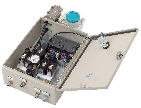
13 13. Additional Tips for Using the LSP1 Air Flushing System The deltaflow is especially resistant to dirty conditions. When metering media that are particularly high in particulate content, however, it may become necessary to perform periodic cleanings of the deltaflow. We recommend using the LSP1 Air Flushing System for this purpose. The LSP is installed between the deltaflow and the dp transducer and is supplied with auxiliary power and compressed air. The LSP is configured to use the compressed air to automatically flush out the deltaflow unit. This ensures the continuous, maintenance-free functionality of the deltaflow even under extreme conditions. Further detailed information is available in the LSP1 spec sheets Integrated Pressure and Temperature Sensors material for insertion, such as copper paste. Integrated temperature measurement is available with and without transducer. If your deltaflow is equipped with a temperature transducer, please take time to become familiar with its description. If desired, the deltaflow can be equipped with optional integrated pressure and temperature sensors and a proper connection box (for easy wiring) Temperature is measured either by a miniature PT100 resistance thermometer or a Type K thermocouple. These are located in a sealed immersion sleeve inside the deltaflow and can be removed under pressure for testing or replacement purposes. To do this, the locknut must be completely opened, and the element can then be withdrawn. Any replacement element must be exactly the same length as the original element and its exterior diameter may measure no more than 2 mm. Please use an appropriate lubricant Pressure is measured by means of a G ½ stud with counterrotated threads located on the stud; for steam it is attached to a siphon and, if desired, an optional Manometer shut-off valve. Insert the sealing gaskets and screw the transducer into the stud. A connection diagram for the pressure transducer is included in the transducer package. systec generally supplies absolute pressure transducers (0..1.6bara) for sampling ranges near the ambient pressure and gauge pressure transducers for higher pressures. Please refer to the equipment label or the sales confirmation document the pressure range should be indicated on both of these. Pre-installed pressure or differential pressure transducers must be tested for integrity after installation. Jostling during transportation can result in leaks or other compromises of integrity. Please retighten any joins that may have become loosened. 13
 for integrated pressure transmitter and temperature sensor (thermocouple Type K) with transmitter 15. Iceproofing / Weatherproof Housing Important!")

14 Wiring (in connection box) for integrated pressure transmitter and PT100-temperature sensor with transmitter (first picture) or without transmitter (second picture) Examples for wiring (in connection box) for integrated pressure transmitter and temperature sensor (thermocouple Type K) with transmitter 15. Iceproofing / Weatherproof Housing Important! Freezing can result in measurement errors and can damage the cells of differential pressure transducers. If the probe is to be installed out-of-doors, it may be necessary to provide some sort of heating unit or a weatherproof housing to ensure that temperatures do not fall below freezing. Please ask us. If you use a deltaflow with a weatherproof box, please pay attention to the connection diagram included in the package. All sealing surfaces and threaded connections must be checked for leaks after installation and must be retightened if necessary Maintenance If the deltaflow is used in media with pollution levels ranging from mild to normal, it will continue to function without any maintenance at all. When the deltaflow is used in applications containing especially high levels of pollution, we recommend using the LSP1 air flushing system. If you are unsure, please ask your dealer or contact systec Controls. 14
15 17.. Troubleshooting The sections below contain a few tips for troubleshooting. We are happy to help you with any difficulties you may encounter please take advantage of our support services. There is no display on my metering system. Has the primary shut-off been opened? Is the dp transducer correctly connected to the electrical source? Is the dp transducer correctly connected mechanically? (Refer to the Installing Pulse Conduits / Connecting the Differential Pressure Transducer section above.) Does the dp transducer register >4mA? If yes, then check your electrical evaluation equipment. My metering system comes up with values that are too high or too low: Has the necessary straight inlet path been provided? (Refer to Selecting an Appropriate Sampling Site chapter.) Is the orientation of the weld-in stud correct? (Refer to Weld-in Stud Orientation chapter.) Are the construction dimensions of the weld-in stud correct? (Refer to Installing the Weld-in Stud chapter.) Is the transducer correctly calibrated? Do the conduit dimensions correspond exactly to the label on your deltaflow? Are the calculations for your deltaflow correct (deltacalc calculation sheet)? You can download our calculation program from our web page free of charge. Does the characteristic curve of the dp transducer correspond to the evaluation (mathematical root extraction)? Have obstructions been installed into the conduit upstream from your deltaflow? Did calculations compensate for ventilation and/or condensation draw during impulse conduit installation? Are differential pressure, pressure, and temperature calculated correctly in the evaluation software? Was a zero-point calibration performed at the dp transducer? (Refer to Zero Point Calibration at the dp Transformer After Installation chapter) My deltaflow does not fit into the conduit: Has the right seal been included? Do the dimensions of the conduit correspond exactly to the sizes listed on your deltaflow label? Does the weld-in stud have the correct dimensions? (Standard dimensions for flange studs are 125mm high above the pipe wall; other studs are available in customized sizes.) Did you reach the opposite support with your deltaflow (opposite support is not standard equipment)? 18.. Additional Information Additional reports and brochures can be obtained through your sales representative or directly from systec Controls. They can also be downloaded free of charge from our website. You will find additional information about the deltaflow, as well as other pertinent information, in the following documents: deltaflow Data sheets deltaflow Calculation Basics deltaflow Brochure deltacalc Evaluation Software 19.. Questions? No one knows the deltaflow better than we do! Take advantage of our expertise we are happy to help you. We have a network of associates in our field sales staff within Germany, and sales representatives in many other countries who stand ready to assist you. To find systec representatives in your area, please consult our web page: Or simply call our headquarters in Puchheim (Germany): systec Controls Hotline: +49-(0)
.DN6000 (236 ) Fluid temperature: -40.")
 Gas")

16 20. Flow meters made by systec systec Controls offers a wide range of precise flow meters made in Germany. The table below gives you some examples. Please vist us at controls.de to get information about our full range of flow meters. deltawavec: ultrasonic clamp-on flow meter for liquids Features Pipe sizes: DN10 (1/3 ).DN6000 (236 ) Fluid temperature: C Media: All common liquids like water, waste water, oil Accuracy: Up to 1% Principle: Ultrasonic time-of-flight Benefits + Non-intrusive, hygienic measurement + Integrated heat measurement as standard + Quick and easy mounting under operation + Quick-setup, large and convenient display + Good value deltaflowc: Mass flow meter for gases Features Pipe sizes: DN20 DN6000 (and bigger) Gas temperature: C Gas pressure: 10 bar Accuracy: Class 2% and 4% available Media: Gases, non-explosive Benefits + Multivariable with pressure/temperature/dp-sensors + 2 Analog outputs for mass flow and temperature or pressure + Ultra-fast: Up to 4000 measurements per second + Good value (starts at 780 ) deltaflow: Averaging pitot tube Features Pipe sizes: mm (models DF8/DF12/DF25/DF44) Pressure: 0 690bar Media: Gas, Steam, Liquids Temperatur: C Ex / ATEX, PED certified Integrated pressure / temperature sensors (optional) Benefits + Precise measurement (<1%) + maintenance-free for most applications + Very low pressure loss + Drift-free measurement 16
17 Notes 17
deltaflowc deltaflowc Venturi or Probe
 deltaflowc Mass Flowmeter for Gases - Multivariable with ultra fast dp, p and T-sensors - Compact, accurate and user-friendly - Ideal for OEMs deltaflowc Venturi or Probe Precise mass flow metering deltaflowc
deltaflowc deltaflowc Gas Massflowmeter Venturi- and Probe Type
 deltaflowc Mass Flowmeter for Gases - Multivariable with ultra fast dp-, p- and T-Sensors - Compact, accurate and user-friendly - Ideal for OEMs deltaflowc Gas Massflowmeter Venturi- and Probe Type Precise
detaflow deltaflow DF44 Data Sheet Flow metering for Gas, Steam and
 detaflow Flow metering for Gas, Steam and deltaflow DF44 Data Sheet Telefon 089-80906-0, Telefax 089-80906-200 http://www.systec-controls.de Overview Operational Conditions Pressure rating: PN160-200 ca.
deltaflowc deltaflowc Venturi or Probe
 deltaflowc Mass Flowmeter for Gases Multivariable with ultra fast dp, p and Tsensors Compact, accurate and userfriendly Ideal for OEMs deltaflowc Venturi or Probe Precise mass flow metering deltaflowc
SERIES 500 VARIABLE RANGE PNEUMATIC DIFFERENTIAL PRESSURE TRANSMITTER
 Man500e 09/2006 Installation Operation and Maintenance Instructions SERIES 500 VARIABLE RANGE PNEUMATIC DIFFERENTIAL PRESSURE TRANSMITTER INDEX 1. INSTALLATION 2. COMPRESSED AIR SUPPLY 3. FLOW MEASURE
detaflow deltaflow DF25 Data Sheet Flow metering for Gas, Steam and Liquid
 detaflow Flow metering for Gas, Steam and Liquid deltaflow DF25 Data Sheet Telefon 089-80906-0, Telefax 089-80906-200 http://www.systec-controls.de Rev. 1.0 en Overview Operational Conditions 0 250 bar
The Discussion of this exercise covers the following points:
 Exercise 5-3 Wet Reference Leg EXERCISE OBJECTIVE Learn to measure the level in a vessel using a wet reference leg. DISCUSSION OUTLINE The Discussion of this exercise covers the following points: Measuring
Ball Float Steam Trap UNA 43 PN 16/CL 125/JIS 10K UNA 46 PN 40/CL 150/CL 300/JIS 10K/JIS 20K DN 80, 100, 150, 3", 4", 6"
 Data Sheet 819584-00 Issue Date: 01/17 Ball Float Steam Trap UNA 43 PN 16/C 125/JIS 10K UNA 46 PN 40/C 150/C 300/JIS 10K/JIS 20K DN 80, 100, 150, 3", 4", 6" UNA 43 hl, UNA 46 hl UNA 43 v, UNA 46 v with
Operating and maintenance manual Filter and reducing station Series / 1.0
 Operating and maintenance manual Filter and reducing station Series 961 04.2017 / 1.0 Original instructions ARCA Regler GmbH. All rights reserved. Cover picture background: Freepik.com ARCA Regler GmbH
Combination Air Valve
 Combination Air Valve For Sewage and Wastewater Model C50 Installation, Operation and Maintenance Manual (IOM) Table of Contents General... Page 2 Safety... Page 2 Operational Data... Page 3 Materials
Exercise 5-2. Bubblers EXERCISE OBJECTIVE DISCUSSION OUTLINE. Bubblers DISCUSSION. Learn to measure the level in a vessel using a bubbler.
 Exercise 5-2 Bubblers EXERCISE OBJECTIVE Learn to measure the level in a vessel using a bubbler. DISCUSSION OUTLINE The Discussion of this exercise covers the following points: Bubblers How to measure
better measurement Simply a question of SCHMIDT Flow Sensor SS The cost-effective alternative in pressurised systems up to 10 bars.
 Simply a question of better measurement SCHMIDT Flow Sensor SS 20.261 The cost-effective alternative in pressurised systems up to 10 bars. Compressed air technology Industrial processes A cost analysis
PC3_ and PC4_ Pipeline Connectors
 1283050/4 IM-P128-06 ST Issue 4 PC3_ and PC4_ Pipeline Connectors Installation and Maintenance Instructions 1. Safety information 2. Description PC30 shown 3. Installation 4. Welding of pipeline connector
DTG - LCD Digital Temperature Gauge USER MANUAL
 DTG - LCD USER MANUAL Page 1 of 7 USERS GUIDE page 1. Description 3 2. Function 3 3. Safety Instruction 3 3.1. Safety Conventions 3 3.2. Proper Use 3 4. Installation 4 4.1. Unpacking 4 4.2. Storage 4 4.3.
ASME and PED Requirements for Drum Level Instrumentation. Presented by: Amir Hedayatnia Clark-Reliance Corp.
 ASME and PED Requirements for Drum Level Instrumentation 2017 Presented by: Amir Hedayatnia Clark-Reliance Corp. Topics Gage Glasses and Remote Reading Instruments ASME Code Section I Requirements for
GM Series Dual-Block Multi-Function Gas Control Valves
 Installation Sheets Manual 121 Gas Combustion Combination Controls and Systems Section G Technical Bulletin GM Issue Date 0297 GM Series Dual-Block Multi-Function Gas Control Valves Figure 1: GM Series
Mounting and operating instructions EB 2530 EN. Self-operated Pressure Regulator. Pressure Reducing Valve Type M 44-2
 Self-operated Pressure Regulator Pressure Reducing Valve Type M 44-2 Type M 44-2, connection G 1 4, K VS = 0.15 Type M 44-2, connection G 1, K VS = 6 Fig. 1 Type M 44-2 Pressure Reducing Valve Mounting
Type BBS-03, BBS-05, BBS-06, BBS-25
 Type BBS-03, BBS-05, BBS-06, BBS-25 Sterile connection elements Sterile Verbindungselemente Raccords union stériles Operating Instructions Bedienungsanleitung Manuel d utilisation 1. THE OPERATING INSTRUCTIONS
Bubble Tube Installations
 Instruction MI 020-328 September 2013 Bubble Tube Installations For Liquid Level, Density, and Interface Level Measurements 2 Contents Introduction... 5 Abbreviations... 5 Principle of Operation... 5 Alternative
Integral type Differential pressure flowmeter VNT Series
 Integral type Differential pressure flowmeter VNT Series OUTLINE VH series Wafer-Cone differential pressure flowmeter and high precision differential pressure transmitter are integrated into one flowmeter.
FPD175 Compact orifice carrier assembly
 ABB MEASUREMENT & ANALYTICS OPERATING INSTRUCTION FPD175 Compact orifice carrier assembly The smart solution for remote applications. Measurement made easy Installation, commissioning and operating / maintenance
Control Valve with ZK Radial Stage Nozzle ZK 210. Original Installation Instructions English
 Control Valve with ZK Radial Stage Nozzle ZK 210 EN English Original Installation Instructions 810691-00 Contents Important Notes Page Usage for the Intended Purpose... 3 Safety Note... 3 Warning... 4
M45 ISO Ball Valve DN25 to 150 Installation and Maintenance Instructions
 BAC 13310 IM-P133-42 ST Issue 2 M45 ISO Ball Valve DN25 to 150 Installation and Maintenance Instructions 1. General safety information 2. General product information 3. Installation 4. Commissioning 5.
Combination Air Valve Model
 Combination Air Valve Model Model C10 /C11 Installation, Operation and Maintenance Manual (IOM) Table of Contents General...Page 2 Safety...Page 2 Operational Data...Page 3 Materials and Connections...Page
Vortex flowmeters. Product family introduction Principle of operation Product review Applications Key product features
 Vortex flowmeters introduction Product review s Key product features This document should not be duplicated, used, distributed, or disclosed for any purpose unless authorized by Siemens. Page 1 Vortex
Assembly Drawing: W-311B-A01, or as applicable Parts List: W-311B-A01-1, or as applicable Special Tools: , , &
 REDQ Regulators Model 411B Barstock Design Powreactor Dome Regulator OPERATION AND MAINTENANCE Contents Scope..............................1 Installation..........................1 General Description....................1
Engineering Data Sheet
 Page 1 of 6 CE MARKING AND THE PRESSURE EQUIPMENT DIRECTIVE 97/23/EC Valves must be installed into a well designed system and it is recommended that the system be inspected in accordance with the appropriate
Flowmeter. Original operating manual DFM
 Flowmeter Original operating manual Series DFM 165 350 Version BA-2016.08.09 EN Print-No. 300 458 TR MA DE Rev002 ASV Stübbe GmbH & Co. KG Hollwieser Straße 5 32602 Vlotho Germany Phone: +49 (0) 5733-799-0
THE MF-400 SERIES. Operating and Service Manual. Series includes all variants of MF-400/401
 THE MF-400 SERIES Operating and Service Manual Series includes all variants of MF-400/401 Issue A October 2013 1 TABLE OF CONTENTS 1. Description... 3 2. Installation... 3 3. Operation... 4 4. Special
k valve 2 (50)HF 2½ (65)SF installation guide aylesbury For valve sizes (DN): tel fax
HF 2½ (65)SF installation guide aylesbury For valve sizes (DN): tel fax") aylesbury k valve installation guide For valve sizes (DN): 2 (50)HF 2½ (65)SF 3 (80)RB IMPORTANT Please keep for future reference. PLEASE READ THESE INSTRUCTIONS CAREFULLY AND REFER TO ANY DIAGRAMS BEFORE
aylesbury k valve installation guide For valve sizes (DN): 2 (50)HF 2½ (65)SF 3 (80)RB IMPORTANT Please keep for future reference. PLEASE READ THESE INSTRUCTIONS CAREFULLY AND REFER TO ANY DIAGRAMS BEFORE
Rapidmain Installation Guide
 Rapidmain Installation Guide Aluminium Compressed Air Pipe Work Installation Guide Trafalgar Court, Waterloo Ind Estate, Widnes Cheshire. UK. Ref: Rapidmain installation guide 4b Index 1. Rapidmain fittings:
Installation and Operation Manual
 Installation and Operation Manual WIKA FLR-SBDF / BLR-SBDF Magnetic Level Transmitter (Please retain for future usage) Contact: Gayesco-WIKA USA, L.P. 229 Beltway Green Boulevard Pasadena, TX 77503 www.wika.com
DK46 - DK800 Supplementary instructions
 DK46 - DK800 Supplementary instructions Variable area flowmeter Device category II2G with electrical internals Additional Ex manual KROHNE CONTENTS DK46 - DK800 1 Safety instructions 3 1.1 General... 3
Installation Manual , Rev BB December Micro Motion H-Series Hygienic Coriolis Flow and Density Sensors
 Installation Manual 20002346, Rev BB December 2010 Micro Motion H-Series Hygienic Coriolis Flow and Density Sensors Safety and approval information This Micro Motion product complies with all applicable
Installation, operating and maintenance Instructions for Seemag bypass level indicator
 Issue: S Date: 05-09-14 Type G35 General information The Seetru bypass magnetic level indicator, abbreviate SEEMAG, serves to show the filling level of fluids in tanks, basins, tubes etc. The Seemag operates
Installation and Maintenance Instruction Manual
 Installation and Maintenance Instruction Manual Bi-metal Thermometer Model A and E in a configuration - pursuant to ASME B40.200: ##=E#=### or ##=ERT#=### - pursuant to EN 13190: ###=A#=### or ##=ART#=###
CARTRIDGE FILTERS TECHNICAL MANUAL MT 080. Installation, commissioning and maintenance instructions. 08/02 Edition
 CARTRIDGE FILTERS TECHNICAL MANUAL MT 080 Installation, commissioning and maintenance instructions 08/02 Edition 1 2 CONTENTS 1.0 PAGE INTRODUCTION 1.1 MAIN FEATURES 1.2 OPERATION 1.3 CLOSING OF HEAD WITH
Mounting and Operating Instructions EB 9520 EN. Differential Pressure and Flow Meter Media 05
 Differential Pressure and Flow Meter Media 05 Fig. 1 Media 05, indicating unit with differential pressure cell, with valve block and pressure gauge (right) Mounting and Operating Instructions EB 9520 EN
Armatures for analytical probes
 Armatures for analytical probes For many different types of installations and applications Large range of probe holders General purpose, water treatment, food & beverage, pharmaceutical applications Type
Orifice Plate Flow Meter
 Orifice Plate Flow Meter FOFT Measuring Principle The principle of measuring the differential pressure is based on the fact that a differential pressure is created across that section of a pipe where its
Installation Operation Maintenance
 682 Seal Cooler New generation seal cooler to meet and exceed the seal cooler requirements stated in the 4th Edition of API Standard 682 Installation Operation Maintenance Experience In Motion Description
THE HF-300 SERIES. Operating and Service Manual. Series includes all variants of HF-300/301
 THE HF-300 SERIES Operating and Service Manual Series includes all variants of HF-300/301 Issue A July 2015 1 TABLE OF CONTENTS 1. Description... 3 2. Installation... 3 3. Operation... 4 3.1. Spring Loaded...
Vortex Flow Meter Wafer or Flange Connection. - Steam - Liquid - Gas
 Vortex Flow Meter Wafer or Flange Connection - Steam - Liquid - Gas Working Principle & Circuit Diagram Working Principle When a column body placed in flowing fluids in pipe, a series of vortices will
Installation, Operation, and Maintenance Manual
 Installation, Operation, and Maintenance Manual Welker The information in this manual has been carefully checked for accuracy and is intended to be used as a guide for the installation, operation, and
Contents. 1. General information BROEN BALLOMAX Steel Ball Valves Approvals Quality Management...2
 Contents 1. General information...2 1.1 BROEN BALLOMAX Steel Ball Valves...2 1.2 Approvals...2 1.3 Quality Management...2 2. Preoperational Instructions and Precautions...2 3. Plates...3 4. Transport and
Ball Float Steam Trap UNA 45 MAX, UNA 46 MAX, UNA 46A MAX PN 40/Class 300 DN 40, 50, 65
 Data Sheet 819346-02 Issue Date: 05/17 Ball Float Steam Trap UNA 45 MAX, UNA 46 MAX, UNA 46A MAX PN 40/Class 300, 50, 65 UNA 45hl MAX, UNA 46hl MAX, UNA 46Ahl MAX UNA 45v MAX with cover for mounting electrode
Best Practice Guide, Servomex 2700
 For full installations details refer to the. Best Practice Guide, Servomex 2700 Mounting: General Guidelines: Servomex 2700 Control Units and air supplies (utilities units) should, ideally, be mounted
The Discussion of this exercise covers the following points: Range with an elevated or suppressed zero Suppressed-zero range Elevated-zero range
 Exercise 4-3 Zero Suppression and Zero Elevation EXERCISE OBJECTIVE In this exercise, you will learn the effect that mounting a pressure transmitter above or below the reference level has on the hydrostatic
Model 130M Pneumatic Controller
 Instruction MI 017-450 May 1978 Model 130M Pneumatic Controller Installation and Operation Manual Control Unit Controller Model 130M Controller is a pneumatic, shelf-mounted instrument with a separate
Level MEASUREMENT 1/2016
 Level MEASUREMENT 1/2016 AGENDA 2 A. Introduction B. Float method C. Displacer method D. Hydrostatic pressure method E. Capacitance method G. Ultrasonic method H. Radar method I. Laser method J. Level
The Discussion of this exercise covers the following points:
 Exercise 3-2 Orifice Plates EXERCISE OBJECTIVE In this exercise, you will study how differential pressure flowmeters operate. You will describe the relationship between the flow rate and the pressure drop
How to specify a product. Process Sensors and Mechanical Instruments
 How to specify a product Process Sensors and Mechanical Instruments Keep the overview. Here is some guideline information on how to specify our products. Intended as supplementary help to specification
Mounting and Operating Instructions EB 2172 EN. Series 43 Temperature Regulators. Type 43-5 and Type Type Type 43-6
 Series 43 Temperature Regulators Type 43-5 and Type 43-7 Type 43-6 Type 43-6 Type 43-7 with flanged valve body, DN 32 to 50 Type 43-5 Type 43-7 with welding ends Mounting and Operating Instructions EB
* * Data Sheet and Operating Manual. Digital manometer ME01 ## # 87 # HL S#### Dust explosion protection Zone 22.
 *09005087* DB_BA_EN_ME01_S Rev.A 12/16 *09005087* d e v e l o p i n g s o l u t i o n s Data Sheet and Operating Manual ME01 Digital manometer Table of Contents ME01 ## # 87 # HL S#### Dust explosion protection
The M-Series Eletta Flow Meter High accuracy DP Flow Meter with multiple functions
 The M-Series Eletta Flow Meter High accuracy DP Flow Meter with multiple functions Flow Meter with multiple functions for gases and liquids M3 The M-series Flow Meter, with its versatile and user-friendly
Installation and Use Manual
 Installation and Use Manual EMASMB & LMASMB Surface Mount Bottle Filling Stations Model EMASMB IMPORTANT THIS IS AN INDOOR APPLICATION ONLY! ALL SERVICE TO BE PERFORMED BY AN AUTHORIZED SERVICE PERSONNEL.
INSTRUCTION MANUAL Pressure Relief Device LPT
 INSTRUCTION MANUAL Pressure Relief Device LPT 5COV475800 LPT REV00 CONTENT: 1 SAFETY 1.1 Safety instructions 2 1.2 Specified applications 2 1.3 Safety notes on the equipment operation 2 2 PRESSURE RELIEF
Spiratec ST14, ST16 and ST17 Sensor Chambers and sensors
 0862050/1 IM-P086-18 MI Issue 1 Spiratec ST14, ST16 and ST17 Sensor Chambers and sensors Installation and Maintenance Instructions 1. Safety Information 2. General product information 3. Installation 4.
Maximum 0.85 MPa pressure setting Long-life, high flow perfect for balancer applications
 Outstanding performance in extremely low pressure and low pressure ranges from 0.003 to. Realizing high performance, energy saving, and compact size. Realize precise pressure control in a pressure range
Inverted Bucket Steam Trap IB 16A-7
 Inverted Bucket Steam Trap IB 16A-7 Original Installation Instructions 819114-02 Contents Preface... 3 Availability... 3 Text layout... 3 Safety... 3 Usage for the intended purpose... 3 Basic safety notes...
RHPS Series RD(H)F40 User Manual. Read the complete manual before installing and using the regulator.
F40 User Manual. Read the complete manual before installing and using the regulator.") RHPS Series RD(H)F40 User Manual Read the complete manual before installing and using the regulator. 2 WARNING Before removing a regulator from the system for service, you must depressurize system purge
RHPS Series RD(H)F40 User Manual Read the complete manual before installing and using the regulator. 2 WARNING Before removing a regulator from the system for service, you must depressurize system purge
PAPR Flow Tester. instructions. part no WARNING
 PAPR Flow Tester part no. 488903 instructions WARNING This manual, including warnings and cautions inside, must be carefully read and followed by all persons who use or maintain the product, including
Differential Pressure Regulator Type Type 45-6 (0.1 to 1 bar, DN 15) Mounting and Operating Instructions EB 3226 EN
 Mounting and Operating Instructions EB 3226 EN") Differential Pressure Regulator Type 45-6 Type 45-6 (0.1 to 1 bar, DN 15) Mounting and Operating Instructions EB 3226 EN Edition March 2008 Contents Contents Page 1 Design and principle of operation...................
Differential Pressure Regulator Type 45-6 Type 45-6 (0.1 to 1 bar, DN 15) Mounting and Operating Instructions EB 3226 EN Edition March 2008 Contents Contents Page 1 Design and principle of operation...................
General page Straight unions page Angle unions page Tee and L-unions page Gauge connection unions page 42
 C 2610-00 Table of contents General page 3-13 DILO unions for pressure ranges from 100 320 bar Straight unions page 14-25 Weld-on tube unions page 14-16 Screw-in tube unions page 17-25 with metric / Whitworth-
KTM OM-2 SPLIT BODY FLOATING BALL VALVES INSTALLATION AND MAINTENANCE INSTRUCTIONS
 Before installation these instructions must be fully read and understood SECTION 1 - STORAGE 1.1 Preparation and preservation for storage All valves should be properly packed in order to protect the parts
RS(H)10,15 USER MANUAL. Read the complete manual before installing and using the regulator.
10,15 USER MANUAL. Read the complete manual before installing and using the regulator.") RS(H)10,15 USER MANUAL Read the complete manual before installing and using the regulator. WARNING INCORRECT OR IMPROPER USE OF THIS PRODUCT CAN CAUSE SERIOUS PERSONAL INJURY AND PROPERTY DAMAGE. Due to
RS(H)10,15 USER MANUAL Read the complete manual before installing and using the regulator. WARNING INCORRECT OR IMPROPER USE OF THIS PRODUCT CAN CAUSE SERIOUS PERSONAL INJURY AND PROPERTY DAMAGE. Due to
Mounting and Operating Instructions EB 3007 EN. Self-operated Pressure Regulators. Differential Pressure Regulators (opening) Type Type 42-25
 Type Type 42-25") Self-operated Pressure Regulators Differential Pressure Regulators (opening) Type 42-20 Type 42-25 Type 42-20 Differential Pressure Regulator Type 42-25 Differential Pressure Regulator Mounting and Operating
Self-operated Pressure Regulators Differential Pressure Regulators (opening) Type 42-20 Type 42-25 Type 42-20 Differential Pressure Regulator Type 42-25 Differential Pressure Regulator Mounting and Operating
INSTRUCTION MANUAL COMPACT PRESS. SWITCHES SERIES PCS & PCA
 COMPACT PRESS. SWITCHES SERIES PCS & PCA WEATHERPROOF SERIES PCS SERIES PCA EXPLOSIONPROOF B B A A B = Cable entry A = Pressure connection WEIGHT 1kg dimensions in mm B = Cable entry A = Pressure connection
INSTRUCTION MANUAL. January 23, 2003, Revision 0
 INSTRUCTION MANUAL Model 810A In-Vitro Test Apparatus for 310B Muscle Lever January 23, 2003, Revision 0 Copyright 2003 Aurora Scientific Inc. Aurora Scientific Inc. 360 Industrial Parkway S., Unit 4 Aurora,
Un-Pressurized Orefice Fittings FIO EZ. Parts List and Operation Instructions TECHNICAL MANUAL. Dn 2-6 Class Lbs
 Un-Pressurized Orefice Fittings FIO EZ Parts List and Operation Instructions TECHNICAL MANUAL Dn 2-6 Class 150-600 Lbs US US 2 FIO EZ - MT 108-US - 05-2016 FIO EZ Important Instructions US Pietro Fiorentini
ALU-CD 12, ALU-CD 25, ALU-CD 35, ALU-CD
 Operating Manual ALU-CD 12, ALU-CD 25, ALU-CD 35, ALU-CD 50 und ALU-CD 60 KGW - ISOTHERM Gablonzer Straße 6 76185 Karlsruhe Germany Tel: 0049 / 721 95897-0 Fax: 0049 / 721 95897-77 Internet: www.kgw-isotherm.com
Electro-Pneumatic Converter YT-940 SERIES
 Electro-Pneumatic Converter YT-940 SERIES PRODUCT MANUAL VERSION 1.00 Contents 1. Introduction 3 1.1 General information for the users. 3 1.2 Manufacturer Warranty 3 1.3 Explosion Proof Warning. 4 2. Product
Preferred Instruments Danbury, CT USA
 Tank Level Sensor Model TG-EL-WF-xx Installation & Operation Instructions SDI-TG-EL-WF March 6, 2006 Preferred Instruments Danbury, CT USA www.preferredinstruments.com CONTENTS Installation Pg. 2 Calibration
Wafer Check Valve. Contents. User s Manual. (1) Be sure to read the following description of our product warranty 1
 Be sure to read the following description of our product warranty 1") Serial No. H-V066-E-3 Wafer Check Valve User s Manual Contents (1) Be sure to read the following description of our product warranty 1 (2) General operating instructions 2 (3) General instructions for
Serial No. H-V066-E-3 Wafer Check Valve User s Manual Contents (1) Be sure to read the following description of our product warranty 1 (2) General operating instructions 2 (3) General instructions for
Instruction Manual Differential Pressure Transmitter
 DE61 Instruction Manual Differential Pressure Transmitter Table of Contents 1. Safety Instructions 2. Intended Applications 3. Product Description and Functions 4. Installation 5. Commissioning 6. Maintenance
Pressure Reducing Valve for Steam Type 2333 A
 Pressure Reducing Valve for Steam Type 2333 A Fig. 1 Type 2333 A 1. Design and principle of operation The pressure reducing valve consists of a balanced control valve and a closing actuator equipped with
Installation, Operation and Maintenance Manual for Back Pressure Regulator
 Installation, Operation and Maintenance Manual for Back Pressure Regulator Model 8860 2009 Groth Corporation IOM-8860 Rev. B 12541 Ref. ID: 95565 Page 2 of 13 Table of Contents I. INTRODUCTION 3 II. DESIGN
Bermad Pressure Reducing. Model: 42T
 Bermad Pressure Reducing Pilot Operated Pressure Control Valve Model: 42T Installation Operation Maintenance Manual (IOM) REV. 27.7.17 Page 1 of 12 Safety First BERMAD believes that the safety of personnel
Instruction Manual Differential Pressure Transmitter
 DE13 Instruction Manual Differential Pressure Transmitter Table of Contents 1. Safety Instructions 2. Intended Applications 3. Product Description and Functions 4. Installation 5. Commissioning 6. Maintenance
TD45 Thermodynamic Steam Trap Installation and Maintenance Instructions
 0685255/1 IM-P068-47 ST Issue 1 TD45 Thermodynamic Steam Trap Installation and Maintenance Instructions 1 General safety information 2 General product information 3 Installation 4 Commissioning 5 Operation
THE BP-301 SERIES. Operating and Service Manual. Series includes all variants of BP-301 (LF 0.1Cv / MF 0.5Cv)
") THE BP-301 SERIES Operating and Service Manual Series includes all variants of BP-301 (LF 0.1Cv / MF 0.5Cv) Issue B October 2015 1 TABLE OF CONTENTS 1. Description... 3 2. Installation... 3 3. Operation...
THE BP-301 SERIES Operating and Service Manual Series includes all variants of BP-301 (LF 0.1Cv / MF 0.5Cv) Issue B October 2015 1 TABLE OF CONTENTS 1. Description... 3 2. Installation... 3 3. Operation...
Mounting and Operating Instructions EB EN. Type Supply Pressure Regulator. with increased air capacity
 Type 4708-45 Supply Pressure Regulator with increased air capacity Translation of original instructions Mounting and Operating Instructions EB 8546-1 EN Edition March 2016 Note on these mounting and operating
SCA Series Inverted Bucket Steam Traps
 0770050/5 IM-P077-06 ST Issue 5 SCA Series Inverted Bucket Steam Traps Installation and Maintenance Instructions 1. General safety information 2. General product information 3. Installation 4. Commissioning
TECHNICAL DATA. Q = C v P S
 Page 1 of 13 1. DESCRIPTION The Viking 6 Model G-6000 Dry Valve Riser Assembly consists of a small profile, light weight, pilot operated valve that is used to separate the water supply from the dry sprinkler
GILMONT ACCUCAL FLOWMETERS
 OPERATING MANUAL GILMONT ACCUCAL FLOWMETERS 28W092 Commercial Ave. Barrington, IL U.S.A. 60010-2392 (847) 381-4888 (847) 381-7053 (Fax) 800-962-7142 www.barnant.com e-mail: barnant@barnant.com A-1299-0766
COMPACT TRIPLE WALL OUTLET STATION MODEL INSTALLATION AND OPERATING INSTRUCTIONS
 COMPACT TRIPLE WALL OUTLET STATION MODEL 6255-1 INSTALLATION AND OPERATING INSTRUCTIONS To assure safe operation and conformation to local fire codes, all Porter Outlet Stations are designed to be used
Steam Trap BK BK 212-ASME. Original Installation Instructions English
 Steam Trap BK 212.. BK 212-ASME EN English Original Installation Instructions 810609-02 1 Contents Page Important Notes Usage for the intended purpose... 3 Safety note... 3 Danger... 3 Attention... 3 Application
INSTRUCTIONS AND MAINTENANCE MANUAL SERIES: K
 INSTRUCTIONS AND MAINTENANCE MANUAL 05/09/2014 SERIES: K cmo@cmo.es http://www.cmo.es Page 1 ASSEMBLY DESCRIPTION Machinery Directive: DIR 2006/42/EC (MACHINERY) Pressure Equipment Directive: DIR 97/23/EC
Target disk flowmeter Series DP. Instructions manual DP65 DP500. R-MI-DP Rev.: 4 English version
 Target disk flowmeter Series DP Instructions manual DP65 DP500 R-MI-DP Rev.: 4 English version PREFACE Thank you for choosing the flowmeter series DP from Tecfluid S.A. This instruction manual allows the
Installation & Operation Manual Proven Quality since 1892
 Content 1. ERIKS operating companies 2. Product description 3. Requirements for maintenance staff 4. Transport and storage 5. Function 6. Application 7. Installation 8. Maintenance 9. Service and repair
Gilflo ILVA and Gilflo ILVA with Mass Flow Transmitter and Compact Stem Flowmetering Systems
 3377150/13 IM-P337-04 MI Issue 13 Gilflo ILVA and Gilflo ILVA with Mass Flow Transmitter and Compact Stem Flowmetering Systems Installation and Maintenance Instructions Gilflo ILVA Gilflo ILVA with mass
C-Flow Coriolis Mass Flow Meters
 Coriolis Mass Flow Meters Ready for Take Off The New Compact C-Flow Küppers Elektromechanik GmbH The C-Flow The C-Flow Coriolis Mass Meters consist of two components: KCE Transmitter KCM Transducer 2 KEM
INSTALLATION INSTRUCTIONS MANUAL ON/OFF SAFETY VALVE/PILOT KIT MODEL GA9050A-1 (F0235)
") P/N 126905-01 Rev. B 11/2016 INSTALLATION INSTRUCTIONS MANUAL ON/OFF SAFETY VALVE/PILOT KIT MODEL GA9050A-1 (F0235) For All Single, Dual and Triple Burner Natural and Propane/LP Gas Logs P126905-01 For
P/N 126905-01 Rev. B 11/2016 INSTALLATION INSTRUCTIONS MANUAL ON/OFF SAFETY VALVE/PILOT KIT MODEL GA9050A-1 (F0235) For All Single, Dual and Triple Burner Natural and Propane/LP Gas Logs P126905-01 For
Flow meter. bellow vaporizer. APL valve. Scavenging system
 Introductory Lecture Series: The Anesthesia Machine PORNSIRI WANNADILOK Objectives Anesthesia Machine Ventilators Scavenging Systems System Checkout 1 Flow meter ventilator bellow vaporizer Corrugated
Wedge Type Flow Meter Installation and Operation Manual
 Wedge Type Flow Meter Installation and Operation Manual 358-EN Please read and save these instructions. Wedge Type Flow Meter PLEASE READ THIS FIRST! The purpose of this document is to provide guidance
Pressure Dump Valve Service Kit for Series 3000 Units
 Instruction Sheet Pressure Dump Valve Service Kit for Series 000 Units. Overview The Nordson pressure dump valve is used to relieve hydraulic pressure instantly in Series 00, 400, 500, and 700 applicator
5 Gallon Pressure Pot with HVLP Spray Gun and Hose
 California Air Tools 5 Gallon Pressure Pot with HVLP Spray Gun and Hose Model No. 365 Technical Data Type of feed.pressure Maximum pressure in the tank... 0,413Mpa (60PSI) Working pressure in the tank.0,
Per Section I of the ASME
 notifies the control room or other Maintenance Safer & Easier remote locations that a probe column The system s intelligence can BOILER INSPECTION GUIDELINES FOR distinguish dirty probes from BOILER INSPECTION
Radar, Ultrasonic and RF Level Transmitters
 Radar, Ultrasonic and RF Level Transmitters Both measures the time it takes the wave to travel between the transmitter and that reflected wave off the surface of the material to reach the transmitter again.
Johnston Invar Coupling Johnston Invar Coupling
 Johnston Invar Coupling Rev.10 (2017.07) AvdS Page 1 of 8 Table of contents I. STRUCTURE OF THE MANUAL / CLARIFICATION... 3 II. SAFETY AND HEALTH CONCERNS... 4 1 GENERAL REMARK... 5 2 ASSEMBLY INSTRUCTIONS...