ORLANDO srl. Chiavari (Ge) Italia Tel: Italia Fax: Italia
|
|
|
- Erica Eustacia Gibbs
- 5 years ago
- Views:
Transcription


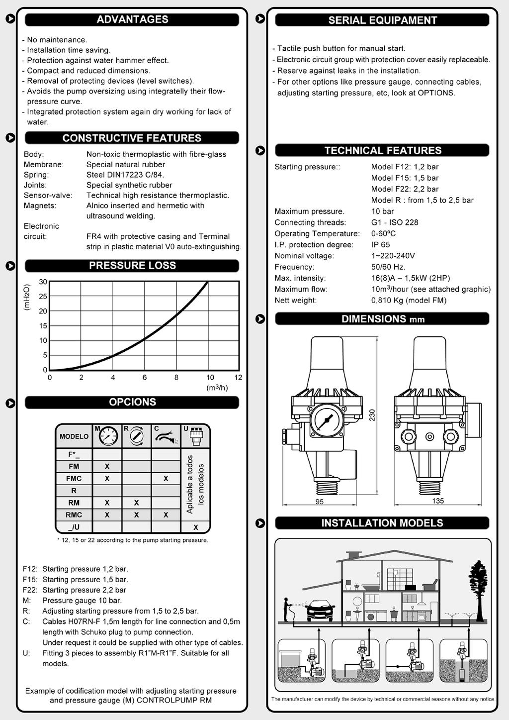
1 Chiavari (Ge) Italia Tel: Italia Fax: Italia orlando@orlando.it TO PRESSCONTROL WT -PRESSURE REGULATOR FOR ELECTRIC PUMPS TO PRESSCONTROL WTD PRESSURE REGULATOR FOR DIESEL TO PRESSCONTROL SK: Circuit board for Presscontrol CA H 05...: Cable for Presscontrol
2 Chiavari (Ge) Italia Tel: Italia Fax: Italia orlando@orlando.it PRESSCONTROL is a device with a new concept that guarantees optimal control of pumps for home use. Deriving from a hydraulic and electronic logics project, it is capable of simultaneously detecting both the pressure and the flow, as well as automatically managing the pump operation. It replaces the traditional expansion tank system, protecting the pump in the case of a water shortage. Far more compact than traditional systems, it is totally reliable, resistant, and easy to install. Applications and Performance Replaces the traditional expansion tank system. Starts and stops the pump in accordance with the opening and closing of the taps. Maintains constant pressure during delivery. Stops the pump in the case of water shortage, protecting it from dry running. Attenuates the effects of water hammering. Maintenance-free. Technical Features - Electrical Parts Monophase power supply voltage : 230V Acceptable voltage variations ± 10% Frequency : Hz Maximum current 8 (8) A Maximum power : 1,5 kw (2 HP) The electronic board accepts minimum voltage variations of 207V and maximum variations of 253V with a frequency of 50/60 Hz. It supports a rated current for resistive loads of up to 16 A, and a rated current for inductive loads of up to 8 A. It is capable of controlling a monophase motor with a maximum power of 1.5 kw equivalent to 2HP Electronic Board Varistor on the line protecting against voltage peaks. Varistor protecting against relay contacts. Relay with two complete 16A contacts in parallel for piloting the monophase motors of up to 2HP. The boards are subjected to burn-in treatment at 50 C for 24 hours with on/off cycles guaranteeing perfect operation in limit conditions and each are individually tested. Technical Features - Electrical Board Box Type 1C device A device that works in such a way as to interrupt the electrical circuit by means of a microswitch (the circuit is opened and closed by relays). Protection degree IP65 The number 6 indicates that the electronic board is completely dust-proof. The number 5 indicates that the electronic board is protected against jets of water arriving from any direction. Maximum operating temperature 65 C The device is built to work in an environment in which the temperature may reach 65 C. Technical Features - Hydraulic Parts Maximum operating pressure 10 bar (1 MPa) Standards establish that that device must: Resist for one minute without any visible loss of pressure equal to twice the maximum operating pressure (20 bar). Resist for one minute at a pressure equal to four times the maximum operating pressure (40 bar). It must also be demonstrated that the device can release a pressure equal to four times the maximum operating pressure (40bar) without dropping in such a way as to be hazardous for humans.
3 Testing of Hydraulic Parts Chiavari (Ge) Italia Tel: Italia Fax: Italia orlando@orlando.it The hydraulic parts of each device are tested individually by means of electronic instruments that detect and memorise the pressure and flow values. In particular, the tests control the following by means of a PLC: Watertight sealing at maximum pressure and therefore the absence of leaks. The intervention value of the pressure gauge (restarting). The value of the minimum flow below which the flow switch stops the pump. Intervention of the stopping function in the event of dry running of the pump. Starting and stopping of the pump. Examples of the components are tested individually to ascertain compliance with the requested technical features. A percentage of the assembled hydraulic parts are tested on test rigs in limit conditions of continuous operation to ascertain their duration over time. COMPONENTS: Body, non-return valve, rear part and safety valve are moulded in 30% fibreglass reinforced polyamide 6 (PA6GF30). This allows for obtaining a high resistance to wear and pressure. The diaphragm is moulded in EPDM ( Ethylene Propylene Diene Monomer). This guarantees exceptional reliability and durability. The flow valve, pressure gauge rod and the diffuser are all in brass (OT58). The dimensional stability of the metal guarantees the operation of the components. The spring is made in UNI 3823 steel wire. The stabilisation process guarantees the operation of the pressure switch, essential for the pump start-up precision and the plant pressure adjustment. The dimensions and structure of the same allow for considerably reducing the effects of water hammering. The box containing the electrical part is moulded in shockproof self-extinguishing polystyrene (PSau). The use of prime materials and top-of-the-range components allows for achieving high levels of dimensional stability, resistance to wear and bursting, and duration over time as opposed to other products made with poorer quality materials and components often not admitted by the EEC standards
4 INSTALLATION: The device can be mounted either directly onto the pump or between the pump and the first tap. If the input pressure of the device exceeds 10 bar (1 MPa), install a pressure reducer between the pump and the device itself. No tap must be mounted between the pump and the device. It is essential to mount the device with the flow arrows pointing upwards (fig. A). It is recommended to connect the output of the device to the plant by means of a ball valve and flexible tube (fig. B). Before starting the device check that the pump is correctly primed. Chiavari (Ge) Italia Tel: Italia Fax: Italia orlando@orlando.it Select the Calibration The PRESSCONTROL comes in three different versions which only vary in their restart pressure calibrations: 1,2 bar (0,12 MPa) 1,5 bar (0,15 MPa) 2,2 bar (0,22 MPa) The restart pressure value is factory-calibrated and cannot be modified. ATTENTION Before installing check that the technical features of the device, pump and system are all compatible. In particular, the pressure generated by the pump must normally be at least 1 bar (0.1 MPa) higher than the restart pressure of the device otherwise the pump will fail to work. 1,2 bar (0,12 MPa) Restart Pressure Calibration The pressure of the pump must be a minimum of 2.5 bar (0.25 MPa), and a maximum of 10 bar (0.1 MPa). The water column between the device and the highest tap must not exceed 10 metres. 1,5 bar (0,15 MPa) Restart Pressure Calibration The pressure of the pump must be a minimum of 3 bar (0.30 MPa), and a maximum of 10 bar (0.1 MPa). The water column between the device and the highest tap must not exceed 15 metres. 2,2 bar (0,22 MPa) Restart Pressure Calibration The pressure of the pump must be a minimum of 3.5 bar (0.35 MPa), and a maximum of 10 bar (0.1 MPa). The water column between the device and the highest tap must not exceed 22 metres.
5 Chiavari (Ge) Italia Tel: Italia Fax: Italia orlando@orlando.it Electrical Wiring It is recommended to always foresee the installation of a omnipolar switch with minimum opening of the contacts, equal to three millimetres, upstream from the device. The monophase pumps (230 V) with motor powers of up to 1. 5 kw (2 HP) can be connected directly to the device, whereas the same pumps with powers exceeding 1.5 kw (2 HP), and all the three-phase pumps (400 V) must be connected to the device by means of a remote control switch. Check the mains voltage and the nameplate data of the pump motor. Use H05 or H07 type cables with a section of 3x1 mm2. Ascertain that the device is connected to the earthing system. Electrical Wiring Direct connection of the 230V monophase motors with an input not exceeding 1.5 kw (2 HP). The use of a remote control switch is not necessary. Electrical Wiring Connection by means of a remote control switch for 230V monophase motors with an input exceeding 1.5 kw (2 HP). Electrical Wiring Connection by means of a remote control switch for 400V3N three-phase motors.
6 Start Up A panel is located on the front of the device that displays the operating phases of the system via the use of pilot lights. Green light: Power On (voltage), yellow light: Pump On, red light: Failure. On connecting to the electrical mains the green pilot light turns on and the yellow one signals the start up of the pump. The pump keeps operating for several seconds in order to allow the system to gain pressure. Should this time be insufficient, the red pilot light will turn on. In this case keep the red Restart button pressed in and wait with a tap opened for the red light to turn off. Once the tap has been closed, the device stops the pump and moves into standby with the green light turned on, ready to carry out all the following command and control operations in full autonomy. Operation - System Operation On opening a tap, the device starts the pump which remains in operation for the same time the tap remains open Tap open Presence of flow Presence of pressure Pump running. Operation - System Under Pressure On closing the tap, the device restores the maximum pressure to the system, stops the pump and returns to the standby position. System closed Absence of flow Presence of pressure Pump stopped Operation - System Stopped In the event of a water shortage during aspiration, the device will recognise the fault, signal the same with the red pilot light Failure, and stop the pump to protect it from dry running. After eliminating the causes of the stopping it is sufficient to press the red Restart button to restore normal operation. In case of a temporary electricity cut-off the device will automatically start up again when the power returns. Tap open Absence of flow Absence of pressure Pump stopped
7 Chiavari (Ge) Italia Tel: Italia Fax: Italia orlando@orlando.it Checking the Operation In the case of faults it is recommended to apply a ball valve to the output of the PRESSCONTROL. This allows for testing the operation of the pump and the device and excluding the system by means of the valve for the purpose of troubleshooting and removing the cause of the malfunctioning.


8 Chiavari ( Ge) Italia Tel: Italia Fax: Italia orland o@ orlan do.it w w.o rlando.it CB FSCB 15: :CONTROLPUMP
9


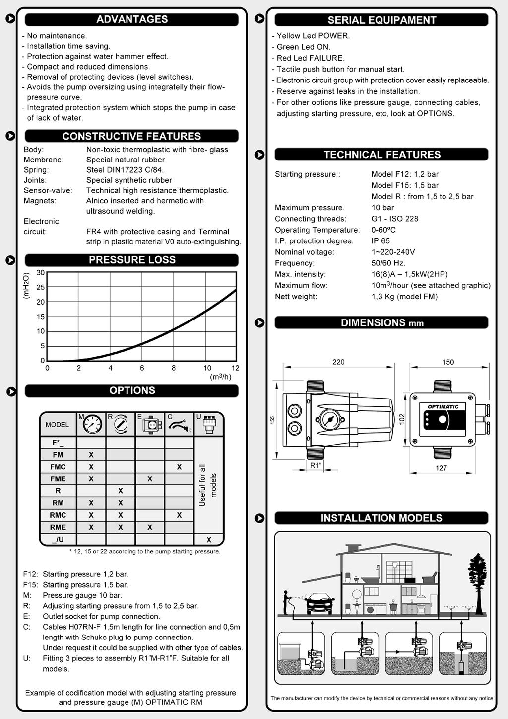
10 Chiavari (Ge) Italia Tel: Italia Fax: Italia orland o@ orlan do.it w w.o rlando.it Our code: CB OPTIMATIC M
11

12 Chiavari (Ge) Italia Tel: Italia Fax: Italia orland o@ orlan do.it w w.o rlando.it TO MASS CONTROL 114: MASCONTROL is the high-powered version of the Presscontrol. The hydraulic parts have been enlarged and foresee 1¼ unions which allow for reducing the pressure losses and offer the advantage of greater flow rate. The electrical parts are structured in such a way as to be able to control monophase pumps with up to 3 HP without the use of remote control switches. These features increase the use possibilities. Applications and Performance Replaces the traditional expansion tank system. Starts and stops the pump in accordance with the opening and closing of the taps. Maintains constant pressure during delivery. Stops the pump in the case of water shortage, protecting it from dry running. Overcomes the effects of water hammering. Maintenance-free. Technical Features - Electrical Parts Monophase power supply voltage: 230V Acceptable voltage variations ± 10% Frequency Hz Maximum current 30 (16) A Maximum power 2,2 kw (3 HP) The electronic board accepts minimum voltage variations of 207V and maximum variations of 253V with a frequency of 50/60 Hz. It supports a rated current for resistive loads of up to 30 A, and a rated current for inductive loads of up to 16 A. t is capable of controlling a monophase motor with a maximum power of 2.2 kw equivalent to 3HP

13 Chiavari (Ge) Italia Tel: Italia Fax: Italia orland o@ orlan do.it Electronic Board w w.o rlando.it Varistor on the line protecting against voltage peaks. Varistor protecting against relay contacts. Relay with two complete 30A contacts in parallel for piloting the monophase motors of up to 3HP. The boards are subjected to burn-in treatment at 50 C for 24 hours with on/off cycles guaranteeing perfect operation in limit conditions and each are individually tested. Technical Features - Electrical Board Box Insulation class II The electrical part of the device is insulated from the outside due to being housed in a sealed box only accessible via the use of tools. Type 1C device A device that works in such a way as to interrupt the electrical circuit by means of a microswitch (the circuit is opened and closed by relays). Protection degree IP65 The number 6 indicates that the electronic board is completely dust-proof. The number 5 indicates that the electronic board is protected against jets of water arriving from any direction. Maximum operating temperature 65 C The device is built to work in an environment in which the temperature may reach 65 C. Technical Features - Hydraulic Parts Maximum operating pressure 10 bar (1 MPa) Standards establish that that device must: Resist for one minute without any visible loss of pressure equal to twice the maximum operating pressure (20 bar). Resist for one minute at a pressure equal to four times the maximum operating pressure (40 bar). It must also be demonstrated that the device can release a pressure equal to four times the maximum operating pressure (40bar) without dropping in such a way as to be hazardous for humans. Testing of Hydraulic Parts The hydraulic parts of each device are tested individually by means of electronic instruments that detect and memorise the pressure and flow values. In particular, the tests control the following by means of a PLC: Watertight sealing at maximum pressure and therefore the absence of leaks. The intervention value of the pressure gauge (restarting). The value of the minimum flow below which the flow switch stops the pump. Intervention of the stopping function in the event of dry running of the pump. Starting and stopping of the pump. Examples of the components are tested individually to ascertain compliance with the requested technical features. A percentage of the assembled hydraulic parts are tested on test rigs in limit conditions of continuous operation to ascertain their duration over time. COMPONENTS:
14 Chiavari (Ge) Italia Tel: Italia Fax: Italia orland o@ orlan do.it w w.o rlando.it Materials Body, non-return valve, rear part and safety valve are moulded in 30% fibreglass reinforced polyamide 6 (PA6GF30). This allows for obtaining a high resistance to wear and pressure. The diaphragm is moulded in EPDM ( Ethylene Propylene Diene Monomer). This guarantees exceptional reliability and durability. The flow valve, pressure gauge rod and the diffuser are all in brass (OT58). The dimensional stability of the metal guarantees the operation of the components. The spring is made in UNI 3823 steel wire. The stabilisation process guarantees the operation of the pressure switch, essential for the pump start-up precision and the plant pressure adjustment. The dimensions and structure of the same allow for considerably reducing the effects of water hammering. The box containing the electrical part is moulded in shockproof self-extinguishing polystyrene (PSau). The use of prime materials and top-of-the-range components allows for achieving high levels of dimensional stability, resistance to wear and bursting, and duration over time as opposed to other products made with poorer quality materials and components often not admitted by the EEC standards. Installation The device can be mounted either directly onto the pump or between the pump and the first tap. If the input pressure of the device exceeds 10 bar (1 MPa), install a pressure reducer between the pump and the device itself. No tap must be mounted between the pump and the device. It is essential to mount the device with the flow arrows pointing upwards (fig. A). It is recommended to connect the output of the device to the system by means of a ball valve and flexible tube (fig. B). Before starting the device check that the pump is correctly primed. Selecting the Calibration The MASCONTROL comes in three versions which only vary in their restart pressure calibrations: 1,2 bar (0,12 MPa) 1,5 bar (0,15 MPa) 2,2 bar (0,22 MPa) The restart pressure value is factory-calibrated and cannot be modified. The restart pressure calibration value is indicated on the rear of the device. ATTENTION Before installing check that the technical features of the device, pump and system are all compatible. In particular, the pressure generated by the pump must normally be at least 1 bar (0.1 MPa) higher than the restart pressure of the device otherwise the pump will fail to work.
15 1,2 bar (0,12 MPa) Restart Pressure Calibration The pressure of the pump must be a minimum of 2.5 bar (0.25 MPa), and a maximum of 10 bar (0.1 MPa). The water column between the device and the highest tap must not exceed 10 metres. 1,5 bar (0,15 MPa) Restart Pressure Calibration The pressure of the pump must be a minimum of 3 bar (0.30 MPa), and a maximum of 10 bar (0.1 MPa). The water column between the device and the highest tap must not exceed 15 metres. 2,2 bar (0,22 MPa) Restart Pressure Calibration The pressure of the pump must be a minimum of 3.5 bar (0.35 MPa), and a maximum of 10 bar (0.1 MPa). The water column between the device and the highest tap must not exceed 22 metres. Electrical Wiring It is recommended to always foresee the installation of a omnipolar switch with minimum opening of the contacts, equal to three millimetres, upstream from the device. The monophase pumps (230 V) with motor powers of up to 2.2 kw (3 HP) can be connected directly to the device, whereas the same pumps with powers exceeding 2.2 kw (3 HP), and all the three-phase pumps (400 V) must be connected to the device by means of a remote control switch. Check the mains voltage and the nameplate data of the pump motor. Use H05 or H07 type cables with a section of 3x1 mm2. Ascertain that the device is connected to the earthing system. Electrical Wiring Direct connection of the 230V monophase motors with an input not exceeding 2.2 kw (3 HP). The use of a remote control switch is not necessary. Electrical Wiring Connection by means of a remote control switch for 230V monophase motors with an input exceeding 2.2 kw (3 HP). Electrical Wiring Connection by means of a remote control switch for 400V3N three-phase motors.

16 Chiavari (Ge) Italia Tel: Italia Fax: Italia orland o@ orlan do.it w w.o rlando.it Start Up A panel is located on the front of the device that displays the operating phases of the system via the use of pilot lights. Green light: Power On (voltage), yellow light: Pump On, red light: Failure. On connecting to the electrical mains the green pilot light turns on and the yellow one signals the start up of the pump. The pump keeps operating for several seconds in order to allow the system to gain pressure. Should this time be insufficient, the red pilot light will turn on. In this case keep the red Restart button pressed in and wait with a tap opened for the red light to turn off. Once the tap has been closed, the device stops the pump and moves into standby with the green light turned on, ready to carry out all the following command and control operations in full autonomy. Operation - System Operation Operation - System Operation On opening a tap, the device starts the pump which remains in operation for the same time the tap remains open. Tap open Presence of flow Presence of pressure Pump running Operation - System Under Pressure On closing the tap, the device restores the maximum pressure to the system, stops the pump, and returns to the standby position. Tap closed Absence of flow Presence of pressure Pump stopped
17 Operation - System Stopped In the event of a water shortage during aspiration, the device will recognise the fault, signal the same with the red pilot light Failure, and stop the pump to protect it from dry running. After eliminating the causes of the stopping it is sufficient to press the red Restart button to restore normal operation. In case of a temporary electricity cut-off the device will automatically start up again when the power returns. Tap open Absence of flow Absence of pressure Pump stopped Chiavari (Ge) Italia Tel: Italia Fax: Italia orland o@ orlan do.it w w.o rlando.it Checking the Operation In the case of faults it is recommended to apply a ball valve to the output of the MASCONTROL. This allows for testing the operation of the pump and the device and excluding the system by means of the valve for the purpose of troubleshooting and removing the cause of the malfunctioning

18 Chiavari (Ge) Italia Tel: Italia Fax: Italia orland o@ orlan do.it w w.o rlando.it TO CONTROLPRES: PRESSURE REGULATOR Apart from the performance of the MASCONTROL, this new device allows for reducing and adjusting the maximum pressure generated by the pump. This allows for obtaining the desired pressure in the system without applying a pressure reducer. In fact, the device accepts an input pressure of a maximum of 12 bar which can be reduced and adjusted from between a minimum of 3 bar and a maximum of 6.5 bar. The hydraulic part has been enlarged and foresees 1¼ unions which allows for reducing the load loss and offers the advantage of greater flow rate. The electrical part is structured in such a way as to be able to control monophase pumps with up to 3 HP without the use of remote control switches. These overall features make CONTROLPRES unique and increase its use possibilities. Applications and Performance Reduces the maximum pressure generated by the pump. Adjusts the system pressure within the established field. Replaces the traditional expansion tank system. Starts and stops the pump in accordance with the opening and closing of the taps. Maintains constant pressure during delivery. Stops the pump in the case of water shortage, protecting it from dry running. Overcomes the effects of water hammering. Maintenance-free.
19 Chiavari (Ge) Italia Tel: Italia Fax: Italia orland o@ orlan do.it Technical Features - Electrical parts w w.o rlando.it - Monophase power supply voltage : 230V - Acceptable voltage variations ± 10% - Frequency : Hz - Maximum current : 30 (16) A - Maximum power : 2,2 kw (3 HP) The electronic board accepts minimum voltage variations of 207V and maximum variations of 253V with a frequency of 50/60 Hz. It supports a rated current for resistive loads up to 30 A, and a rated current for inductive loads up to 16 A. It is capable of controlling a monophase motor with a maximum power of 2.2 kw equivalent to 3HP. Electronic Board Varistor on the line protecting against voltage peaks. Varistor protecting against relay contacts. Relay with two complete 30A contacts in parallel for piloting the monophase motors up to 3HP. The boards are subjected to burn-in treatment at 50 C for 24 hours with on/off cycles guaranteeing perfect operation in limit conditions and each individually tested. Technical Features - Electrical Board Box Insulation class II The electrical part of the device is insulated from the outside due to being housed in a sealed box only accessible via the use of tools. Type 1C device A device that works in such a way as to interrupt the electrical circuit by means of a microswitch (the circuit is opened and closed by relays). Protection degree IP65 The number 6 indicates that the electronic board is completely dust-proof. The number 5 indicates that the electronic board is protected against jets of water arriving from any direction. Maximum operating temperature 65 C The device is built to work in an environment in which the temperature may reach 65 C. Technical Features - Hydraulic Parts Maximum operating pressure 12 bar (1.2 MPa) Standards establish that the device must: Resist for one minute without any visible loss of pressure equal to twice the maximum operating pressure (24 bar). Resist for one minute at a pressure equal to four times the maximum operating pressure (48 bar). It must also be demonstrated that the device can release a pressure equal to four times the maximum operating pressure (48 bar) without dropping in such a way as to be hazardous for humans. Minimum system pressure 3 bar (0,30 MPa). Maximum system pressure 6.5 bar (0,65 Mpa) Materials Body, non-return valve, rear part and knob are moulded in 30% fibreglass reinforced polyamide 6 (PA6GF30). This allows for obtaining a high resistance to wear and pressure. The diffuser diaphragm and gasket are moulded in EPDM ( Ethylene Propylene Diene Monomer ). This guarantees exceptional reliability and durability. The flow valve, pressure gauge rod and the diffuser are all in brass (OT58). The dimensional stability of the metal guarantees the operation of the components. The spring is made in UNI 3823 steel wire. The stabilisation process guarantees the operation of the pressure switch, essential for the pump start-up precision and the system pressure adjustment. The dimensions and structure of the same allow for considerably reducing the effects of water hammering. The box containing the electrical part is moulded in shockproof self-extinguishing polystyrene (PSau). The use of prime materials and top-of-the-range components allows for achieving high levels of dimensional stability, resistance to wear and bursting and duration over time as opposed to other products made with poorer quality materials and components often not admitted by the EEC standards.

20 Chiavari ( Ge) Italia Tel: Italia Fax: Italia orland o@ orlan do.it Testing of Hydraulic Parts w w.o rlando.it The hydraulic parts of each device are tested individually by means of electronic instruments that detect and memorise the pressure and flow values. In particular, the tests control the following by means of a PLC: Watertight sealing at maximum pressure and therefore the absence of leaks. The intervention value of the pressure gauge (restarting). The value of the minimum flow below which the flow switch stops the pump. Intervention of the stopping function in the event of dry running of the pump. Starting and stopping of the pump. Examples of the components are tested individually to ascertain compliance with the requested technical features. A percentage of the assembled hydraulic parts are tested on test rigs in limit conditions of continuous operation to ascertain their duration over time. Operation - System Operation On opening a tap, the device starts the pump which remains in operation for the same time the tap remains open. Tap open Presence of flow Presence of pressure Pump running Installation The device can be mounted either directly onto the pump or between the pump and the first tap. The input pressure of the device must not exceed 12 bar (1.2 MPa). No tap must be mounted between the pump and the device. It is essential to mount the device with the flow arrows pointing upwards (fig. A). It is recommended to connect the output of the device to the system by means of a ball valve and flexible tube (fig. B). Before starting the device check that the pump is correctly primed. Adjustment knob (fig. D). The pressure gauge of the device allows for ascertaining the pressure value of the system (fig. C). Operation - System Under Pressure On closing the tap, the device restores the maximum pressure to the system, stops the pump and returns to the standby position. System closed Absence of flow Presence of pressure Pump stopped
21 Operation - System Stopped In the event of a water shortage during aspiration, the device will recognise the fault, signalling the same with the red pilot light Failure, and stopping the pump to protect it from dry running. After eliminating the causes of the stopping it is sufficient to press the red Restart button to restore normal operation. In case of a temporary electricity cut-off the device will automatically start up when the power returns. Tap open Absence of flow Absence of pressure Pump stopped Chiavari ( Ge) Italia Tel: Italia Fax: Italia orland o@ orlan do.it w w.o rlando.it Adjusting the Pressure of the System Open a tap to start up the pump, close it again and wait for the pump to stop in order to read the system pressure on the pressure gauge, which is normally factory-calibrated at 3 bar. To adjust the pressure open the tap again, turn the knob in a clockwise direction to increase the pressure, and in an anticlockwise direction to reduce it, close the tap and with the pump stopped read the pressure set on the pressure gauge. Repeat this operation until the desired pressure value is reached. The system pressure (P2) must be approximately 1.5 bar lower than the pump pressure (P1), and approximately 1 bar higher than the pressure in the water column feeding the Controlpres (P3). If the pressure of the pump (P1) fails to reach the values indicated in the pressure adjustment table, the pump will stop working. In the event of the height of the water column (P3) being higher than the values indicated in the pressure adjustment table, the pump will turn on without starting to operate. To overcome this shortcoming either position the device higher up in order to recreate the conditions specified above, or set a higher system pressure (P2).
22 Adjustment Example P1 - Pressure pump (maximum 12 bar) P2 - System pressure (maximum 6,5 bar) P3 - Water column pressure P4 - Tap pressure How to deliver a 3 bar pressure to the tap located at a height of 30 m: pressure requested by the tap = 3 bar = P4 tap height 30 m = 3 bar = P3 The system pressure (P2) must be adjusted to 6 bar, seeing that P2 = P4 + P3. T he pump pressure (P1) must be a minimum of 7.5 bar, seeing that P1 = P2 + 1,5 bar. Adjustament Table To help the installer adjust the device, the manual illustrates the pressure values generated by the pump and the height of the water column in relation to the pressure that it is necessary to obtain in the system (for the sake of simplicity these are listed in 0.5 bar steps without taking intermediate values into account). Pressure of the system adjusted to 3.0 bar (0.30 MPa) The pressure of the pump must be a minimum of 4.5 bar (0.45 MPa), and a maximum of 12 bar (1.2 MPa). The water column between the device and the highest tap must not exceed 12 metres. Pressure of the system adjusted to 3.5 bar (0.35 MPa) The pressure of the pump must be a minimum of 5.0 bar (0.50 MPa), and a maximum of 12 bar (1.2 MPa). The water column between the device and the highest tap must not exceed 16 metres. Pressure of the system adjusted to 4.0 bar (0.40 MPa) The pressure of the pump must be a minimum of 5,5 bar (0.55 MPa), and a maximum of 12 bar (1.2 MPa). The water column between the device and the highest tap must not exceed 20 metres. Pressure of the system adjusted to 4.5 bar (0.45 MPa) The pressure of the pump must be a minimum of 6.0 bar (0.60 MPa), and a maximum of 12 bar (1.2 MPa). The water column between the device and the highest tap must not exceed 25 metres. Pressure of the system adjusted to 5.0 bar (0.50 MPa) The pressure of the pump must be a minimum of 6.5 bar (0.65 MPa), and a maximum of 12 bar (1.2 MPa). The water column between the device and the highest tap must not exceed 30 metres. Pressure of the system adjusted to 5.5 bar (0.55 MPa) The pressure of the pump must be a minimum of 7.0 bar (0.70 MPa), and a maximum of 12 bar (1.2 MPa). The water column between the device and the highest tap must not exceed 35 metres. Pressure of the system adjusted to 6.0 bar (0.60 MPa) The pressure of the pump must be a minimum of 7.5 bar (0.75 MPa), and a maximum of 12 bar (1.2 MPa). The water column between the device and the highest tap must not exceed 40 metres. Pressure of the system adjusted to 6.5 bar (0.65 MPa) The pressure of the pump must be a minimum of 8.0 bar (0.80 MPa), and a maximum of 12 bar (1.2 MPa). The water column between the device and the highest tap must not exceed 45 metres.
: a primary chamber (C1) which contains the maximum pressure generated by the")
23 How Controlpres Reduces and Adjusts the Pressure The reduction and adjustment of the pressure are obtained by exploiting the pressure reducer system. The CONTROLPRES body is subdivided into two chambers (separated or communicating with a diffuser fitted with a shutter): a primary chamber (C1) which contains the maximum pressure generated by the pump (P1); a secondary chamber (C2) where the pressure (P2) is reduced and adjusted to the value necessary in the system. When the pump has stopped, the chambers do not communicate as the diffuser is closed due to the pressure in the primary chamber being higher than that of the secondary chamber. When the pump is operating, the chambers communicate as the diffuser is more or less open due to the fact that a pressure differential is created between the primary chamber and the secondary chamber depending on the adjustment. The pressure differential is determined by the force of the spring that can be reduced or increased by turning the adjustment knob of the device. In this way the desired pressure is obtained in the system, which is in any case lower than the pressure generated by the pump and can be adjusted between a minimum of 3 bar and a maximum of 6.5 bar. IMPORTANT: The CONTROLPRES does not have a fixed restart pressure calibration. The restart pressure value increases with the increasing of the pressure value set on the system and decreases with a reduction of the same.

24 Checking the Operation In the case of faults it is recommended to apply a ball valve to the output of the CONTROLPRES. This allows for testing the operation of the pump and the device and excluding the system by means of the valve for the purpose of troubleshooting and removing the cause of the malfunctioning. By closing the ball valve it is also possible to read the effective pressure obtained with the adjustment on the pressure gauge. Electrical Wiring It is recommended to always foresee the installation of a omnipolar switch with minimum opening of the contacts, equal to three millimetres, upstream from the device. The monophase pumps (230 V) with motor powers of up to 2.2 kw (3 HP) can be connected directly to the device, whereas the same pumps with powers exceeding 2.2 kw (3 HP) and all the three-phase pumps (400 V), must be connected to the device by means of a remote control switch. Check the mains voltage and the nameplate data of the pump motor. Use H05 or H07 type cables with a section of 3x1.5 mm 2. Ascertain that the device is connected to the earthing system. Direct connection of the 230V monophase motors with an input not exceeding 2.2 kw (3 HP). The use of a remote control switch is not necessary. Connection by means of a remote control switch for 230V monophase motors with an input exceeding 2.2 kw (3 HP). Connection by means of a remote control switch for 400V3N three-phase motors. Advantages of the Controlpres The CONTROLPRES is the only product on the market that apart from controlling the pump also reduces and adjusts its pressure. It manages monophase pumps with powers of up to 3 HP, avoiding the use of remote control switches, offering savings for the tap and tap-friendly installation for the plumber (who need not resort to intervention by electricians). Its special technical feature of reducing and adjusting the pressure ensures an additional economic advantage as it overcomes the need to install a pressure reducer and eliminates subsequent costs.

25 Chiavari ( Ge) Italia Tel: Italia Fax: Italia orland o@ orlan do.it w w.o rlando.it TO ECOPRESS: Just like PRESSCONTROL, ECOPRESS also replaces the traditional expansion tank system, automatically managing the pump operation and simultaneously detecting the pressure and flow. It maintains a constant pressure during use and protects the pump from dry running. The compact dimensions, simplified control panel and tapfriendliness all make ECOPRESS the ideal accessory for controlling small pumps for home and gardening use. Applications and Performance Replaces the traditional expansion tank system. Starts and stops the pump in accordance with the opening and closing of the taps. Maintains constant pressure during delivery. Stops the pump in the case of water shortage, protecting it from dry running. Overcomes the effects of water hammering. Maintenance-free. Technical Features - Electrical parts - Monophase power supply voltage : 230V - Acceptable voltage variations : ± 10% - Frequency :50-60 Hz - Maximum current :10 (6) A - Maximum power : 1,1 kw (1,5 HP) The electronic board accepts minimum voltage variations of 207V and maximum variations of 253V with a frequency of 50/60 Hz. It supports a rated current for resistive loads of up to 10 A, a rated current for inductive loads of up to 6. It is capable of controlling a monophase motor with a maximum power of 1.1 kw equivalent to 1.5 HP. Electronic Board Varistor on the line protecting against voltage peaks. Varistor protecting against relay contacts. Relay with two complete 16A contacts in parallel for piloting the monophase motors up to 1.5 HP. The boards are subjected to burn-in treatment at 50 C for 24 hours with on/off cycles guaranteeing perfect operation in limit conditions and each individually tested.
. Protection degree IP65 The number 6 indicates that the electronic board is completely dust-proof.")
26 Technical Features - Electrical board box Type 1C device A device that works in such a way as to interrupt the electrical circuit by means of a microswitch (the circuit is opened and closed by relays). Protection degree IP65 The number 6 indicates that the electronic board is completely dust-proof. The number 5 indicates that the electronic board is protected against jets of water arriving from any direction. Maximum operating temperature 60 C The device is built to work in an environment in which the temperature may reach 60 C. Technical Features - Hydraulic parts Maximum operating pressure 10 bar (1 MPa) Standards establish that that device must: Resist for one minute without any visible loss of pressure equal to twice the maximum operating pressure (20 bar). Resist for one minute at a pressure equal to four times the maximum operating pressure (40 bar). It must also be demonstrated that the device can release a pressure equal to four times the maximum operating pressure (40bar) without dropping in such a way as to be hazardous for humans. Testing of Hydraulic Parts The hydraulic parts of each device are tested individually by means of electronic instruments that detect and memorise the pressure and flow values. In particular, the tests control the following by means of a PLC: Watertight sealing at maximum pressure and therefore the absence of leaks. The intervention value of the pressure gauge (restarting). The value of the minimum flow below which the flow switch stops the pump. Intervention of the stopping function in the event of dry running of the pump. Starting and stopping of the pump. Examples of the components are tested individually to ascertain compliance with the requested technical features. A percentage of the assembled hydraulic parts are tested on test rigs in limit conditions of continuous operation to ascertain their duration over time. COMPONENTS:
. This guarantees exceptional reliability and durability.")
27 Materials Body, non-return valve, rear part and safety valve are moulded in 30% fibreglass reinforced polyamide 6 (PA6GF30). This allows for obtaining a high resistance to wear and pressure. The diffuser diaphragm and gasket are moulded in EPDM ( Ethylene Propylene Diene Monomer ). This guarantees exceptional reliability and durability. The flow valve, pressure gauge rod and the diffuser are all in brass (OT58). The dimensional stability of the metal guarantees the operation of the components. The spring is made in UNI 3823 steel wire. The stabilisation process guarantees the operation of the pressure switch, essential for the pump start-up precision and the system pressure adjustment. The dimensions and structure of the same allow for considerably reducing the effects of water hammering. The box containing the electrical part is moulded in shockproof self-extinguishing polystyrene (PSau). The use of prime materials and top-of-the-range components allows for achieving high levels of dimensional stability, resistance to wear and bursting and duration over time as opposed to other products made with poorer quality materials and components often not admitted by the EEC standards. Selecting the Calibration The ECOPRESS comes in three different versions which only vary in their restart pressure calibrations: 1,2 bar (0,12 MPa) 1,5 bar (0,15 MPa) 2,2 bar (0,22 MPa) The restart pressure value is factor-calibrated and cannot be modified. The restart pressure calibration value is indicated on the rear of the device. ATTENTION Before installing check that the technical features of the device, pump and system are compatible. In particular, the pressure generated by the pump must normally be at least 1 bar (0.1 MPa) higher than the restart pressure of the device otherwise the pump will fail to work. 1.2 bar (0.12 MPa) Restart Pressure Calibration The pressure of the pump must be a minimum of 2.5 bar (0.25 MPa), and a maximum of 10 bar (0.1 MPa). The water column between the device and the highest tap must not exceed 6 metres. 1.5 bar (0.15 MPa) Restart Pressure Calibration The pressure of the pump must be a minimum of 3 bar (0.30 MPa), and a maximum of 10 bar (0.1 MPa). The water column between the device and the highest tap must not exceed 8 metres. 2.2 bar (0.22 MPa) Restart Pressure Calibration The pressure of the pump must be a minimum of 3.5 bar (0.35 MPa), and a maximum of 10 bar (0.1 MPa). The water column between the device and the highest tap must not exceed 10 metres.
28 Electrical Wiring It is recommended to always foresee the installation of a omnipolar switch with minimum opening of the contacts, equal to three millimetres, upstream from the device. The monophase pumps (230 V) with motor powers of up to 1.1 kw (1.5 HP) can be connected directly to the device, whereas the same pumps with powers exceeding 1.1 kw (1.5 HP) all the three-phase pumps (400 V), must be connected to the device by means of a remote control switch. Check the mains voltage and the nameplate data of the pump motor. Use H05 or H07 type cables with a section of 3x1 mm 2. Ascertain that the device is connected to the earthing system. Direct connection of the 230V monophase motors with an input not exceeding 1.1 kw (1.5 HP). The use of a remote control switch is not necessary. Connection by means of a remote control switch for 230V monophase motors with an input exceeding 1.1 kw (1.5 HP). Connection by means of a remote control switch for 400V3N three-phase motors.


29 CHIAVARI (GE ) - ITALIA Tel.: ITALIA Fax: ITALIA orlando@orlando.it IT BRIO: IT BRIO M


30 CHIAVARI (GE ) - ITALIA Tel.: ITALIA Fax: ITALIA orlando@orlando.it

31 CHIAVARI (GE ) - ITALIA Tel.: ITALIA Fax: ITALIA orlando@orlando.it LIQUID FLOW SWITCH FS FF82: Casing in shock-proof thermoplastic AISI 301 stainless steel blades for pipes from G1" to G8" Direct fixing by threaded connection G1"


32 CHIAVARI (GE ) - ITALIA Tel.: ITALIA Fax: ITALIA orlando@orlando.it


33 CHIAVARI (GE ) - ITALIA Tel.: ITALIA Fax: ITALIA orlando@orlando.it Codice FS Flow switch CALEFFI 1
34
35
36 CHIAVARI (GE ) - ITALIA Tel.: ITALIA Fax: ITALIA orlando@orlando.it


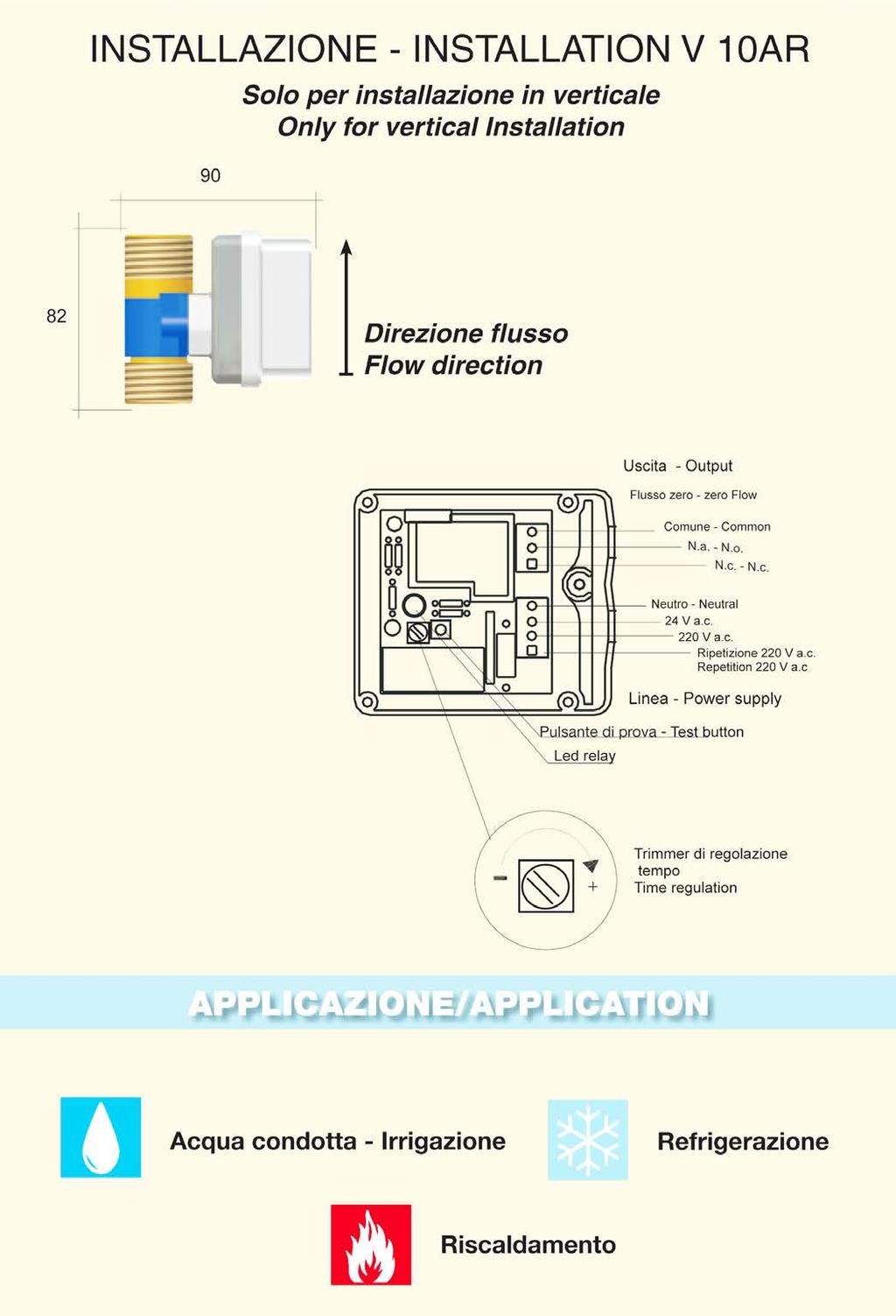
37 CHIAVARI (GE ) - ITALIA Tel.: ITALIA Fax: ITALIA orlando@orlando.it MT FLOW MATIC H 10 AR
38


39 CHIAVARI (GE ) - ITALIA Tel.: ITALIA Fax: ITALIA orlando@orlando.it MT FLOW MATIC V 10 AR MT FLOW MATIC V PLC
40

41 Chiavari (Ge) Italia Tel.: Italy Fax: Italy orlando@orlando.it INVERTER FOR PUMPS FEATURES: Single-phase Inverter 230V-50Hz for single-phase pumps up to 1,5 HP ( 8,5 Ampere max) Wall installation through 4 holes Automatic setting of the working parameters ( electric & mechanical parameters of the pump connected to the inverter are self-entered ) Cover of thermo-resistant glazed PC Dissipator of extruded aluminium Diaphragm panel with key to adjust the pressure ( + - ) and additional functions setting ( advanced set) Micro-led pressure gauge for the pressure display on the diaphragm panel Supplied with pressure transducer with 1/4 Gas screw Cable with Schuko single-phase plug for direct connection to the mains Cable with Schuko single-phase plug for direct connection to the electric pump IP 65 Protection against dry running with automatic reset of the working after a possible stop. Protection against no delivery working Protection against overvoltage Protection against extreme motor absorption Feeding within the range V 50/60 Hz Speed adjustment range up to 10% of the nominal pump's speed Use, maintenance and installation manual


 and it is easy to be installed even on old systems as there is no need to remove the")
42 Chiavari (Ge) Italia Tel.: Italy Fax: Italy orlando@orlando.it The Pump inverter is an electronic device with frequency converter specifically designed for the control in feedback of surface single-phase pumps, submersible or suitable to pump warm or refrigerated water not depending on the flow or the pressure. It replaces the control systems traditionally used in booster pump sets ( pressure switches/ pressure regulators ) and it is easy to be installed even on old systems as there is no need to remove the existing control systems. Motor rpm are being adjusted according to the system requirement, enabling a substantial energy savings above all at the intermediate deliveries. It constantly assures the pressure required by the user and a soundproof working thanks to progressive starting and soft stop, helping to eliminate the water hammering and to have a huge reduction of the starting current. Moreover the control logic of the inverter protects the pump against dry running and anomalous electrical and mechanical pump's conditions. The Pump Inverter allows a medium energy saving a 40% ( compared to the standard on-off systems) during working and a further savings thanks to the stand-by position with stopped pump. INSTALLATION OF E NEW SYSTEM Electric pump connected hydraulically 1) Close the delivery outlet 3) Install the pressure trasducer 4) Connect the Inverter to the Electric pump 6) Press start 2) Remove the drain plug on the Pump casing 5) Connect the Inverter to the mains

 Disconnect the cable feeding The pressure switch 6)")
 Remove the pressure gauge 5) Install the pressure")
43 Chiavari (Ge) Italia Tel.: Italy Fax: Italy orlando@orlando.it INSTALLATION ON OLD SYSTEMS WITH THE PUMP CONTROLLED BY PRESSURE SWITCH Old system controlled by pressure switch 3) Disconnect the cable feeding The pressure switch 6) Connect the inverter to the Electric pump 1) Close the delivery outlet 2) Disconnect the feeding cable from the mains 4) Remove the pressure gauge 5) Install the pressure transducer 7) Connect the inverter to the mains 8) Press START

 Disconnect the cable feeding the Pressure regulators 6)")
 Connect the inverter to the mains 2) Disconnect the feeding cable")
44 Chiavari (Ge) Italia Tel.: Italy Fax: Italy orlando@orlando.it INSTALLATION ON OLD SYSTEMS WITH THE PUMP CONTROLLED BY PRESSURE REGULATOR Old system controlled by pressure regulator 3) Disconnect the cable feeding the Pressure regulators 6) Connect the Inverter to the electric pump 1) Close the delivery outlet 4) Remove the drain plug on the Pump casing 7) Connect the inverter to the mains 2) Disconnect the feeding cable From the mains 5) Install the pressure transducer 8) Press START
45 Chiavari (Ge) Italia Tel.: Italy Fax: Italy orlando@orlando.it
46 Chiavari (Ge) Italia Tel.: Italy Fax: Italy orlando@orlando.it

47 PROFESSIONAL USE For every inverter: it is supplied n.1 K16 pressure trasnducer - The storage temperature must be kept Between 20 C and + 60 C - Ambient temperature must be between 0 C and + 40 C

48 PROFESSIONAL USE For every inverter: it is supplied n.1 K16 pressure trasnducer - The storage temperature must be kept Between 20 C and + 60 C - Ambient temperature must be between 0 C and + 40 C

49 PROFESSIONAL USE For every inverter: it is supplied n.1 K16 pressure trasnducer - The storage temperature must be kept Between 20 C and + 60 C - Ambient temperature must be between 0 C and + 40 C
KIT. Small Automatic Water Boosters KIT MODELS
 KIT Small Automatic Water Boosters The electronic controller KIT orders the automatic start and stop of the water pump when opening or closing any tap or valve in the installation. There are four main
Installation, Operation and Maintenance Instructions for Electronically Controlled Pressurisation Units
 Installation, Operation and Maintenance Instructions for Electronically Controlled Pressurisation Units Models: EPS Single Pump EPT Twin Pump EPS-HP EPT-HP Single Pump High Pressure Twin Pump High Pressure
Pressure independent control valve (PICV) FLOWMATIC
 FLOWMATIC") Pressure independent control valve (PICV) FLOWMATIC 145 series FM 21654 003 01262/19 GB replaces dp 01262/17 GB Function The pressure independent control valve is a device composed of an automatic flow
Pressure independent control valve (PICV) FLOWMATIC 145 series FM 21654 003 01262/19 GB replaces dp 01262/17 GB Function The pressure independent control valve is a device composed of an automatic flow
ECONORESS ELECTRONIC EPS & EPT - ENHANCED PRESSURISATION SET INSTALLATION OPERATION & MAINTENANCE DOCUMENTATION
 ECONORESS ELECTRONIC EPS & EPT - ENHANCED PRESSURISATION SET INSTALLATION OPERATION & MAINTENANCE DOCUMENTATION OCT2010 STOKVIS ENERGY SYSTEMS 96R WALTON ROAD EAST MOLESEY SURREY KT8 0DL TEL: 020 87833050
Components for air preparation and pressure adjustment. OUT port position ( ) connected Rear side. of IN port. Air tank. directly.
 connected Rear side. of IN port. Air tank. directly.") Components preparation and pressure adjustment ABP Overview ABP is a component that enables boosting by s only up to twice primary pressure (.0MPa max.) in combination with using air tank but not using
Components preparation and pressure adjustment ABP Overview ABP is a component that enables boosting by s only up to twice primary pressure (.0MPa max.) in combination with using air tank but not using
Installation, Operation and Maintenance Instructions for Electronically Controlled Pressurisation Units Digital Range
 Installation, Operation and Maintenance Instructions for Electronically Controlled Pressurisation Units Digital Range Models: DS 126 Single Pump / Single System DT 126 Twin Pump / Single System DS 160
AUTOMATIC HOSE TEST UNIT, TYPE SPU
 VALVES AND FITTINGS UP TO 14,000 BAR TEST AND CONTROL EQUIPMENT H IGH PRESSURE TECHNOLOGY AUTOMATIC HOSE TEST UNIT, TYPE SPU Pressure range from 1 up to 10,000 bar User-friendly touch panel operation HIGH-PRESSURE
differential pressure regulating valve - threaded
 140-142 differential pressure regulating valve - threaded Introduction Differential pressure regulating valves (DPRV) maintain the differential pressure across a circuit or sub-branch at a set differential
Installation, use and maintenance instructions. Gas burner (5)
") Installation, use and maintenance instructions Gas burner MODEL GAS 4 TYPE 516 T80 291 (5) TECHNICAL FEATURES Thermal output 180-470 kw 154.800-404.200 kcal/h Fuel Natural gas Pci 8-10 kwh/m 3 = 7000-8600
Installation, use and maintenance instructions Gas burner MODEL GAS 4 TYPE 516 T80 291 (5) TECHNICAL FEATURES Thermal output 180-470 kw 154.800-404.200 kcal/h Fuel Natural gas Pci 8-10 kwh/m 3 = 7000-8600
Budget Range Operators Handbook
 Budget Range Operators Handbook BAMBI AIR COMPRESSORS LTD 152 Thimble Mill Lane Heartlands Birmingham B7 5HT United Kingdom Tel: 0121 322 2299 Fax: 0121 322 2297 Email: sales@bambi-air.co.uk www.bambi-air.co.uk
INSTRUCTION MANUAL COMPACT PRESS. SWITCHES SERIES PCS & PCA
 COMPACT PRESS. SWITCHES SERIES PCS & PCA WEATHERPROOF SERIES PCS SERIES PCA EXPLOSIONPROOF B B A A B = Cable entry A = Pressure connection WEIGHT 1kg dimensions in mm B = Cable entry A = Pressure connection
CCT-7320/ROC-2313 Reverse Osmosis Controller
 CCT-7320/ROC-2313 Reverse Osmosis Controller 1 General The instrument is a combined control instrument of a reverse osmosis controller and an on-line conductivity instrument. It can perform the operation
System Pressure Manager Standard & System Pressure Manager Plus
 System Pressure Manager Standard & System Pressure Manager Plus Installation, Commissioning & Servicing Instructions Note: THESE INSTRUCTIONS MUST BE READ AND UNDERSTOOD BEFORE INSTALLING, COMMISSIONING,
Multiple Pressure Booster Systems With Variable Speed Controller Type BL
 Multiple Pressure Booster Systems With Variable Speed Controller Type BL General Characteristics - Single or multistage pumps - Horizontal or vertical mounting - Total head 30m ~ 250m - Material construction:
Data Sheet Issue A
 Features 1. Differential latching clappertype, lighweight, dependable construction. 2. Low Air Pressurized System, 8 psi -to- 26 psi (0,6 bar to- 1,8 bar) 3. Reset externally. Cover removal is not required.
EXH. Specifications. Descriptions. Min. working pressure MPa
 Functional explanation Primary pressure flowed from passes through check valve on side, and flows in chamber A and B. Primary pressure also passes through pressure adjustment section and switching valve,
Chemical Feed Equipment Floor-Mounted Gas Dispenser - Series CH4200
 Specification Bulletin (rev.01) Series CH4200 Chemical Feed Equipment Floor-Mounted Gas Dispenser - Series CH4200 Easy, fast& accurate digital with 11 points calibration Laser sensor offering actual feed
Measurement of Low GAS & Liquid Flows
 Measurement of Low GAS & Liquid Flows The Measurement Measurement with a float in a tapered borosilicate glass tube. Series 2100 with a 100 mm flow tube Series 2150 with a 150 mm flow tube Series 2300
Filling valves AL, ALM Series Automatic filling units ALOMDIW, ALOMDNW Series
 Filling valves AL, ALM Series Automatic filling units ALOMDIW, ALOMDNW Series Main features Designed for automatic filling of sealed heating systems and for protection of the water mains from risk of contamination.
Self-operated Pressure Regulators for special applications
 Self-operated Pressure Regulators for special applications Type 2357-31 Pressure Build-up Regulator with safety function and integrated excess pressure valve Application Pressure regulators for cryogenic
INSTRUCTION MANUAL FOR MODEL 7360V VERTICAL CURING CHAMBER Revision E May
 INSTRUCTION MANUAL FOR MODEL 7360V VERTICAL CURING CHAMBER Revision E May 2015 98-0520 S/N 2001 N. Indianwood Ave. Tulsa, Oklahoma 74012 U.S.A. TEL: (918) 250-7200 FAX: (918) 459-0165 E-mail: chandler.sales@ametek.com
VR46.5V(A)/VR86.5V(A) SERIES
/VR86.5V(A) SERIES") VR46.5V(A)/VR86.5V(A) SERIES COMACT COMBINATION GAS CONTROS WITH INTEGRATED 1:1 GAS/AIR REGUATOR FOR AUTOMATIC IGNITION SYSTEMS SECIFICATIONS INSTRUCTION SHEET Subject to change without notice. rinted
VR46.5V(A)/VR86.5V(A) SERIES COMACT COMBINATION GAS CONTROS WITH INTEGRATED 1:1 GAS/AIR REGUATOR FOR AUTOMATIC IGNITION SYSTEMS SECIFICATIONS INSTRUCTION SHEET Subject to change without notice. rinted
TECHNICAL DATA. Q = C v P S
 Page 1 of 13 1. DESCRIPTION The Viking 6 Model G-6000 Dry Valve Riser Assembly consists of a small profile, light weight, pilot operated valve that is used to separate the water supply from the dry sprinkler
1. PARTS INTRODUCTION ELECTRICAL NOTES INSTALLATION 5/6. 5. START UP 6/7. 6. MAINTENANCE 7/8/9. 7. PRESSURE SWITCH ADJUSTMENTS 9/10.
 CONTENTS 1. PARTS 3. 2. INTRODUCTION 4. 3. ELECTRICAL NOTES 5. 4. INSTALLATION 5/6. 5. START UP 6/7. 6. MAINTENANCE 7/8/9. 7. PRESSURE SWITCH ADJUSTMENTS 9/10. 8. ELECTRICAL CONNECTIONS 10/11. 9. SPECIFICATIONS
Model DDX-LP Dry Pipe Valve System 8 (200mm) Features. Differential latching clapper-type, lighweight, dependable construction.
 Features. Differential latching clapper-type, lighweight, dependable construction.") Bulletin 335 Model DDX-LP Dry Pipe Valve System 8 (200mm) Bulletin 335 Features 1. 2. 3. 4. 5. 6. 7. 8. 9. 10. 11. 12. Differential latching clapper-type, lighweight, dependable construction. Low Air Pressurized
Bulletin 335 Model DDX-LP Dry Pipe Valve System 8 (200mm) Bulletin 335 Features 1. 2. 3. 4. 5. 6. 7. 8. 9. 10. 11. 12. Differential latching clapper-type, lighweight, dependable construction. Low Air Pressurized
CALEFFI. Ball zone valves. series /03 GB
 all zone valves series cert. n ISO / Function Zone valves are used to automatically shut-off the flow of carrier fluid distributed to a system. Specifically: -In central heating systems, they support the
TECHNOLOGIES. M Series. Positive return metering pumps [API675]
![TECHNOLOGIES. M Series. Positive return metering pumps [API675]](/thumbs/90/101415964.jpg "TECHNOLOGIES. M Series. Positive return metering pumps [API675]") M Series Positive return metering pumps [API675] Hydraulic double diaphragm metering pump in AISI 316L stainless steel A line of plunger and hydraulic double diaphragm metering pumps designed according
M Series Positive return metering pumps [API675] Hydraulic double diaphragm metering pump in AISI 316L stainless steel A line of plunger and hydraulic double diaphragm metering pumps designed according
3 GALLON, OILLESS PANCAKE COMPRESSOR INSTRUCTIONS. Item #31289
 3 GALLON, OILLESS PANCAKE COMPRESSOR INSTRUCTIONS Item #31289 The EASTWOOD 3 GALLON, OILLESS PANCAKE COMPRESSOR, with an Integral Air Regulator, efficiently supplies all compressed air requirements for
GRUNDFOS DATA BOOKLET. Hydro Solo-E. Complete pressure boosting systems 50/60 Hz
 GRUNDFOS DATA BOOKLET Complete pressure boosting systems 5/6 z Contents Product data Performance range 3 Operating conditions Inlet pressure Type key Product range 5 Construction 5 Installation 5 Mechanical
Operating instructions Safety Rope Emergency Stop Switches ZB0052 / ZB0053 ZB0072 / ZB0073
 Operating instructions Safety Rope Emergency Stop Switches UK ZB0052 / ZB0053 ZB0072 / ZB0073 7390878 / 02 03 / 2011 Contents 1 Safety instructions...3 2 Installation / set-up...4 2.1 Applications...4
Art PRESSURE REDUCER
 FUNCTION ICMA pressure reducers are devices that reduce and stabilize the incoming pressure from the water supply. Pressure reducers allow correct use on domestic systems, reducing malfunctions due to
TEK-SUB 4800B. Submersible Level Transmitter. Flow Level Temperature Pressure Valves Analyzers Accessories TekValSys LEVEL
 Technology Solutions TEK-SUB 4800B Submersible Level Transmitter LEVEL Flow Level Temperature Pressure Valves Analyzers Accessories TekValSys Introduction The Tek-Sub 4800B Submersible Level Transmitter
Installation, Operation and Maintenance Instructions for Electronically Controlled Pressurisation Units
 Installation, Operation and Maintenance Instructions for Electronically Controlled Pressurisation Units Micro-S / Micro-S Digital Wall Hung Unit Please fulfil all listed requirements prior to and during
FLOW. State of the Art ELECTRONIC PUMPS CONTROLLERS. * Electronic starters. * Inverters. * Protection devices YOURWATER UNDER CONTROL
 PRODUCT CATALOGUE State of the Art * Electronic starters * Inverters * Protection devices For * Stable Pressure Control * Dry Run Protection * Energy Saving * Water Saving YOURWATER UNDER CONTROL DPI Trading
Hydro Dome GRUNDFOS INSTRUCTIONS
 GRUNDFOS INSTRUCTIONS Hydro Dome Installation and operating instructions Montage- und Betriebsanleitung Notice d installation et d entretien Istruzioni di installazione e funzionamento Instrucciones de
Cover Page for Lab Report Group Portion. Pump Performance
 Cover Page for Lab Report Group Portion Pump Performance Prepared by Professor J. M. Cimbala, Penn State University Latest revision: 02 March 2012 Name 1: Name 2: Name 3: [Name 4: ] Date: Section number:
Installation and Maintenance Manual. ECO Filtration Unit with 6-way-Top-Mount-Valve. Art. Nr
 Installation and Maintenance Manual ECO Filtration Unit with 6-way-Top-Mount-Valve Art. Nr. 300100 300101 300102 Important Details: - Using of this filtration unit for swimming pools and its guard band
Model 130M Pneumatic Controller
 Instruction MI 017-450 May 1978 Model 130M Pneumatic Controller Installation and Operation Manual Control Unit Controller Model 130M Controller is a pneumatic, shelf-mounted instrument with a separate
TECHNICAL DATA 3 MODEL G-3000 DRY VALVE RISER ASSEMBLY
 Page 1 of 13 1. DESCRIPTION The Viking 3 Model G-3000 Dry Valve Riser Assembly is equipped with a small profile, light weight, pilot operated valve that is used to separate the water supply from the dry
TECHNICAL DATA. Q = C v P S
 January 6, 2012 Preaction 348a 1. Description Viking supervised Surefire Preaction Systems utilize the Viking G-6000P Valve. The small profile, lightweight, pilot operated Viking G-6000P Valve comes complete
TECHNICAL DATA. Q= Cv S
 Page 1 of 13 1. DESCRIPTION The Viking 4 inch Model G-4000 Dry Valve Riser Assembly consists of a small profile, light weight, pilot operated valve that is used to separate the water supply from the dry
TECHNICAL DATA Q = C. v P S. 2 Model G-2000 Dry valve. Page 1 of 13
 Page 1 of 13 1. Description The Viking 2 Model G-2000 Dry Valve Riser Assembly consists of a small profile, light weight, pilot operated valve that is used to separate the water supply from the dry sprinkler
Mounting and Operating Instructions EB 3007 EN. Self-operated Pressure Regulators. Differential Pressure Regulators (opening) Type Type 42-25
 Type Type 42-25") Self-operated Pressure Regulators Differential Pressure Regulators (opening) Type 42-20 Type 42-25 Type 42-20 Differential Pressure Regulator Type 42-25 Differential Pressure Regulator Mounting and Operating
Self-operated Pressure Regulators Differential Pressure Regulators (opening) Type 42-20 Type 42-25 Type 42-20 Differential Pressure Regulator Type 42-25 Differential Pressure Regulator Mounting and Operating
ELADOS EDP L Diaphragm Metering Pump Type
 ELADOS EDP L Diaphragm Metering Pump Type 04800-06700 Motor-driven diaphragm pump with integrated frequency converter High reserves due to a powerful asynchronous motor High flexibility due to variably
Installation, commissioning and servicing instructions
 488.03 www.reece.com.au Pressure reducing s Installation, commissioning and servicing instructions Function Pressure reducing s are installed in residential water systems to reduce and stabilise inlet
VACUUM REGULATORS CONTENTS
 CAD drawing data catalog is available. ACCESSORIES GENERAL CATALOG AIR TREATMENT, AUXILIARY, VACUUM, AND FLUORORESIN PRODUCTS CONTENTS Small Regulators Features 759 Specifications, Order Codes, Flow Rate
Simple Set Max. Pressure Independent Control Valves 2 Way 2-1/ /09/18
 The Bray Simple Set Max is a flanged pressure independent control (PIC) valve designed for a wide variety of hot water and chilled water control applications. The SSM Series combines high rangeability
Gas density monitor With integrated transmitter Model GDM-100-TI
 SF 6 gas solutions Gas density monitor With integrated transmitter Model GDM-100-TI grid Products WIKA data sheet SP 60.05 for further approvals see page 5 Applications Gas density monitoring of closed
TECHNICAL DATA OBSOLETE
 April 9, 2009 Preaction 326a 1. DESCRIPTION Viking supervised Double-Interlocked Electric/Pneumatic Release Preaction Systems utilizing the Viking G-4000P Deluge Valve. The small profi le, lightweight,
CONDUCTIVITY POINT/S LEVEL SWITCH JAYCEEAQUA 4000 SERIES
 I N S T R U C T I O N - M A N U A L CONDUCTIVITY POINT/S LEVEL SWITCH JAYCEEAQUA 4000 SERIES FUNCTION: Conductivity level limit switches are based on the principle of measuring level through the electrical
Automatic Control Unit. Controlmatic E.2. Type Series Booklet
 Automatic Control Unit Controlmatic E.2 Type Series Booklet Legal information/copyright Type Series Booklet Controlmatic E.2 All rights reserved. The contents provided herein must neither be distributed,
Gas Check. Short testing time, with automatic start-up if no leakage was detected from previous operation.
 Quality Products at Competitive Prices Gas Check Automatic testing of the down-stream installation to check that all valves are closed and that pipework and fittings are gas tight before each system start-up.
PC10 Piezoresistive Silicon Pressure Sensor
 PC10 Piezoresistive Silicon Pressure Sensor Features With constant current and constant voltage excitation options Imported highly reliable pressure die Wide temperature compensation Normalized output
Features. Model DDX-LP Dry Pipe Valve System 4 (100mm), 6 (150mm) & 165mm Sizes
, 6 (150mm) & 165mm Sizes") Bulletin 357 Rev. E Model DDX-LP Dry Pipe Valve System 4 (100mm), 6 (150mm) & 165mm Sizes Bulletin 357 Rev. E Features 1. 2. 3. 4. 5. 6. 7. 8. 9. Differential-type valve, lightweight, dependable construction.
Bulletin 357 Rev. E Model DDX-LP Dry Pipe Valve System 4 (100mm), 6 (150mm) & 165mm Sizes Bulletin 357 Rev. E Features 1. 2. 3. 4. 5. 6. 7. 8. 9. Differential-type valve, lightweight, dependable construction.
TECHNICAL DATA. Q = C v P S
 Preaction 346a 1. Description The 6 Model G-6000P Electric Release Preaction System Riser Assembly can be used as a Single Interlock Preaction System with Electric Release, or as a Double Interlock Preaction
T EK-SUB 4800C 19 mm Submersible Level Transmitter
 Technology Solutions T EK-SUB 4800C 19 mm Submersible Level Transmitter Instruction Manual Document Number: IM-4800C www.tek-trol.com Table of Contents 1 Safety Instructions... 2 1.1 Intended Use... 2
Glass tube flowmeters Series 2000
 Glass tube flowmeters Series 2000 Variable area flowmeter for low flows of liquids and gases Short mounting length and compact construction, especially indicated for control panels Easy installation. No
MANUAL KPS Pressure Control Valve
 TetraTec Instruments GmbH Gewerbestrasse 8 71144 Steinenbronn Deutschland E-Mail: info@tetratec.de Tel.: 07157/5387-0 Fax: 07157/5387-10 MANUAL Pressure Control Valve *** VERSION 1.0 *** Update: 17.11.2006
High Performance BSP Dial Up Pattern Pressure Reducing Valve
 See our full range online at: www.vip-ltd.co.uk High Performance BSP Dial Up Pattern Pressure Reducing Valve VIP Product Code 31/0103 FUNCTION Pressure reducing valves are devices which, when installed
![[Instruments for vacuum measurement, checking and adjustment] 3](/thumbs/94/121874202.jpg "[Instruments for vacuum measurement, checking and adjustment] 3")
AIR DRIVEN. Gas Boosters & SYSTEMS. Accepting VISA, MasterCard and American Express
 AIR DRIVEN Gas Boosters & SYSTEMS Accepting VISA, MasterCard and American Express Gas Boosters AIR DRIVEN FROM 30 PSI TO 21,750 PSI MAXIMATOR Maximator gas boosters are an excellent alternative to high
Installation, operating and maintenance Instructions for Seemag bypass level indicator
 Issue: S Date: 05-09-14 Type G35 General information The Seetru bypass magnetic level indicator, abbreviate SEEMAG, serves to show the filling level of fluids in tanks, basins, tubes etc. The Seemag operates
By-pass valves Series 466 Thermatic - Series USVR
 By-pass valves Series 466 Thermatic - Series USVR Main features - Available in the following version : Female/Female series 466 1/2, 3/4, 1 Female/Male series USVR 3/4, 1, 1.1/4 - Conforms to standard:
Tightness controls TC 1 3 and TC 4
 Tightness controls TC 1 3 and TC 4 Test of both safety valves Short test period thanks to logical decision-making in the program sequence Adjustable test period which can be adapted to different systems
Installation and commissioning instructions 255 series and 256 series
 Installation and commissioning instructions 255 series and 256 series Table of contents 1 General information... 3 1.1 About these instructions... 3 1.2 About this product... 3 1.3 Appropriate usage...
TECHNICAL DATA. Q = C v P S
 January 6, 2012 Preaction 333a 1. Description Viking supervised Surefire Preaction Systems Utilize the Viking G-3000P Valve. The small profile, lightweight, pilot-operated Viking G-3000P Valve comes complete
VERTICAL AIR COMPRESSORS
 VERTICAL AIR COMPRESSORS MODEL NO: VE15C150, VE18C150, VE25C150 PART NO: 2226010, 2226020, 2226025 OPERATION & MAINTENANCE INSTRUCTIONS LS0715 INTRODUCTION Thank you for purchasing this CLARKE Vertical
Control & Maintenance. INT69 Diagnose INT69 TM Diagnose. Protect the heart of your system
 Control & Maintenance INT69 Diagnose INT69 TM Diagnose Protect the heart of your system R INT69 DIAGNOSE The widely known protective system INT69 and INT69 TM present on all Frascold compressors is now
Propane Conversion Kit Instructions
 604 8 0/ US/CA For heating engineers Propane Conversion Kit Instructions Logano G4 X gas-fired boiler This conversion kit and the accompanying instructions are for conversion of G4 X gas-fired boilers
TECHNICAL DATA. Q = C v P S
 January 6, 2012 Preaction 347a 1. Description Viking supervised Double-Interlocked Electric/Pneumatic Release Preaction Systems utilize the Viking G-6000P Valve. The small profile, lightweight, pilot operated
Blue River Technologies Port-A-Poly Mixer w/2.5 GPH LMI Pump And Secondary Water Dilution Line INSTALLATION AND OPERATION
 Blue River Technologies Port-A-Poly Mixer w/2.5 GPH LMI Pump And Secondary Water Dilution Line INSTALLATION AND OPERATION Install your Blue River Technologies Port-A-Poly mixing system in a clean dry area.
BUBBLER CONTROL SYSTEM
 BUBBLER CONTROL SYSTEM Description: The HDBCS is a fully automatic bubbler system, which does liquid level measurements in water and wastewater applications. It is a dual air compressor system with, air
better measurement Simply a question of SCHMIDT Flow Sensor SS The cost-effective alternative in pressurised systems up to 10 bars.
 Simply a question of better measurement SCHMIDT Flow Sensor SS 20.261 The cost-effective alternative in pressurised systems up to 10 bars. Compressed air technology Industrial processes A cost analysis
Pre-adjustable pressure reducing valves with self-contained cartridge
 Pre-adjustable pressure reducing valves with self-contained cartridge 535..H series ACCREDITED ISO 91 FM 15 15/17 GB replaces 15/1GB Function Pressure reducing valves are devices which, when installed
Data sheet Pressure switch type CS December 2001 DKACT.PD.P10.A B1119
 Pressure switch type CS December 2001 DKACT.PD.P10.A2.02 520B1119 Introduction Pressure switch type CS is part of the Danfoss pressure control range. All CS pressure switches have a built-in pressure-operated,
Calibrated or locked versions available. TREATMENT > Series MD regulators GENERAL DATA. New
 > Series MD regulators Series MD pressure regulators New Ports with interchangeable cartridges: threaded (1/8, 1/4, /8) or integrated with super-rapid fitting for tube with Ø 6, 8 and 10 mm Versions: single,
Automatic Control Unit. Controlmatic E. Type Series Booklet
 Automatic Control Unit Controlmatic E Type Series Booklet Legal information/copyright Type Series Booklet Controlmatic E All rights reserved. The contents provided herein must neither be distributed, copied,
Advanced Pump Control for Irrigation Applications
 Advanced Pump Control for Irrigation Applications Paul Nistler VFD Applications Engineer And Julian Atchia Director of Research and Development SJE Rhombus 22650 County Hwy 6 Detroit Lakes MN 56502 Executive
Electronic Single and Twin Pump System Pressure Managers
 Electronic Single and Twin Pump System Pressure Managers Installation, Commissioning & Servicing Instructions Note: THESE INSTRUCTIONS MUST BE READ AND UNDERSTOOD BEFORE INSTALLING, COMMISSIONING, OPERATING
Flamco Flamco-Fill STA Flamco-Fill STM
 STA STM Typ STA 5936 Typ STM 5937 GB Installation and operating instructions 1999, 2 Contents GB UK Limited P.O. Box 9, Washway Lane, St. Helens, Merseyside WA10 6FE United Kingdom Telephone: 01744 744744
TECHNICAL DATA. Q = C v P S
 January 6, 2012 Preaction 331a 1. Description Viking supervised Double-Interlocked Electric/Pneumatic Release Preaction Systems utilize the Viking G-3000P Valve. The small profile, lightweight, pilot-operated
Data Sheet Issue A
 Features 1. Differential-type valve, lightweight, dependable construction. 2. Low Air Pressurized System, 10 psi -to- 26 psi (0,7 bar -to- 1,8 bar). 3. Reset externally.cover removal is not required. 4.
HBLT-A1 LIQUID LEVEL SENSOR
 Instruction manual HBLT-A1 LIQUID LEVEL SENSOR for measuring liquid level in refrigerant vessels Instruction manual HBLT - A1 - Liquid level Transmitter (HBLT-A1-008-UK) 1 / 16 Contents Safety instructions...
Mounting and Operating Instructions EB EN. Type Supply Pressure Regulator. with increased air capacity
 Type 4708-45 Supply Pressure Regulator with increased air capacity Translation of original instructions Mounting and Operating Instructions EB 8546-1 EN Edition March 2016 Note on these mounting and operating
The Univentor 1250 Anaesthesia Unit
 THE UNIVENTOR 1200/1250 ANAESTHESIA UNIT The Univentor 1250 Anaesthesia Unit TABLE OF CONTENTS EDITION 1 Section 1 - WARRANTY & SERVICE 1.1. WARRANTY 2 1.2. DAMAGED SHIPMENTS 2 1.3. SERVICE 2 Section 2
L 100. Bubble-Tube Level System. Installation, Operation and Maintenance Instructions
 L 100 Bubble-Tube Level System Installation, Operation and Maintenance Instructions Figure 1 Contents Section Description Page 1.0 Introduction 2 2.0 Specifications 3 3.0 Installation 3 4.0 Warranty 6
Sullair Air Systems. *Assessment of the market for compressed air efficiency services. Technical report, U.S. Department of Energy, June 2001
 Sullair Air Systems The three most expensive components in operating a compressed air system are: inadequate, inefficient controls that waste energy; lost production due to an improperly maintained system;
Compact differential pressure switch Flameproof enclosure Ex d Models DE, DEC
 Mechatronic pressure measurement Compact differential pressure switch Flameproof enclosure Ex d Models DE, DEC WIKA data sheet PV 35.41 Process Compact Series Applications Differential pressure monitoring
Pressure transmitters EMP 2
 Data sheet Pressure transmitters EMP 2 The high accuracy pressure transmitter EMP 2 is designed for monitoring and control in marine and industial applications and offers a reliable pressure measurement,
UBEC 1AT. AUTO TANK Fill System Installation, Operation, & Setup Instructions
 Document Number: XE-ATA5PM-R1A UBEC 1AT AUTO TANK Fill System 08899155 Installation, Operation, & Setup Instructions Rev170906-EB-FRC PHYSICAL: 1302 WEST BEARDSLEY AVE ELKHART, IN 46514 WWW.ELKHARTBRASS.COM
Automatic Control Unit. Cervomatic EDP.2. Type Series Booklet
 Automatic Control Unit Cervomatic EDP.2 Type Series Booklet Legal information/copyright Type Series Booklet Cervomatic EDP.2 All rights reserved. The contents provided herein must neither be distributed,
Differential Pressure Control Valve (DPCV)
") Differential Pressure Control Valve (DPCV) PATENTED Technical Data and Installation Instructions Page 1 V2 The modulating valves ART 241 balance and control the differential pressure (DPCV) automatically
Differential Pressure Control Valve (DPCV) PATENTED Technical Data and Installation Instructions Page 1 V2 The modulating valves ART 241 balance and control the differential pressure (DPCV) automatically
36E DSI, HSI & Proven Pilot Two-Stage Combination Gas Valve INSTALLATION INSTRUCTIONS
 INLET PRESS TAP WTE-RODGERS 36E96-314 DSI, HSI & Proven Pilot Two-Stage Combination Gas Valve INSTALLATION INSTRUCTIONS Operator: Save these instructions for future use! FAILURE TO READ AND FOLLOW ALL
* * Data Sheet and Operating Manual. Digital manometer ME01 ## # 87 # HL S#### Dust explosion protection Zone 22.
 *09005087* DB_BA_EN_ME01_S Rev.A 12/16 *09005087* d e v e l o p i n g s o l u t i o n s Data Sheet and Operating Manual ME01 Digital manometer Table of Contents ME01 ## # 87 # HL S#### Dust explosion protection
Pressure Transmitters 36 F-27839
 Pressure Transmitters 36 F-27839 SPD310/SPD360 Air Differential schneider-electric.com 37 SPD310/SPD360 SPD310/SPD360 differential pressure transmitters are intended for use in air handling systems for
Pressure switch Type BCP
 Data sheet Pressure switch Type BCP The BCP type is a series of dedicated switches for safety and monitoring of steam and hot water boilers. The BCP incorporates a single-pole changeover microswitch where
INSTALLATION OPERATION MAINTENANCE
 Bermad Electrically Controlled On-Off Deluge Valve Model: 400E-3D INSTALLATION OPERATION MAINTENANCE Application Engineering BERMAD 1. Safety First BERMAD believes that the safety of personnel working
C-Flow Coriolis Mass Flow Meters
 Coriolis Mass Flow Meters Ready for Take Off The New Compact C-Flow Küppers Elektromechanik GmbH The C-Flow The C-Flow Coriolis Mass Meters consist of two components: KCE Transmitter KCM Transducer 2 KEM
Installation, commissioning and servicing instructions
 3838.10 www.caleffi.com Inclined pressure reducing s opyright 2018 aleffi 33 series Installation, commissioning and servicing instructions Function Pressure reducing s are installed in residential water
Temperature Controllers
 IM0004 April 2013 CONTENTS T-12 Thermostat PAGE Introduction 1 Scope 1 Description 1 Specification 1 Temperature Controllers 2 INTRODUCTION CAUTION Prior to installing, the instructions provided herein