/'J ' Isaacs-kidd midwater trawl. T u- ,vc# C-> SIO REFERENCE ^ina/ report: UNIVERSITY OF CALIFORNIA SCRIPP5 INSTITUTION OF OCEANOGRAPHY
|
|
|
- Silvia Anderson
- 5 years ago
- Views:
Transcription

1

2 0 M 1 X,vC# CO io a> 00 vy UNIVERSITY OF CALIFORNIA SCRIPP5 INSTITUTION OF OCEANOGRAPHY Q_ O C-> 1 y T u- 9 1 /'J ' Isaacs-kidd midwater trawl ^ina/ report: i; j'? oceanographic equipment report no JANUARY 1953 SIO REFERENCE 53-3
3 «r abstract The Isaacs-Kidd Midwater TrawJ collects bathypelagic biological specimens larger and more active than those taken by standard plankton nets. The trawl consists essentially of a net of special design attached to a wide, V-shaped, rigid diving vane. The vane keeps the mouth of the net open and exerts a depressing force, maintainii^ the trawl at depth for extended periods at towing speeds up to five kt. The inlet opening is imobstructed by the towing cable. The new trawl has been successfully tested to a depth of approximately 3700 m. It has already collected several species of bathypelagic fishes not reported from the Pacific before, and species new to scientific literature. This report describes the tests conducted to evaluate the device, discusses the results, and includes sections on conclusions and recommendations for further work., NOTE: This report supersedes the earlier report, A Midwater Trawl by John D. Isaacs and Lewis W. mdd, ^0_Reference_^ 51-51, 15 November 1951, a preliminary report issued wliile THeTrawl was still under development. The work on the Isaacs-Kidd Midwater Trawl has been sponsored jointly by three government agencies. They are the Bureau of Ships fcontractnobsr NE 12Q2air61, the Marine Research CommitleTof the State of California, and the U.S. Navy Office of Naval Research (Project NR Contract N6oii - in, T.O. VI)
4 ' V fl I* < I, INCED' University of California Scripps Institution of Oceanography Isaacs-kidd midwater trawi,j^final REPiitT J Designers John D. Isaacs Lewis W. Kidd (g)- V3A)Co^^~UWt Oceanographic Equipment Report No. 1 Report prepared by; \I^J Robert F./oevereux^ &dttrrr RobertCJWinsettill < D D'C'v EterasiiE JAU i2 19fT? EISHruib - fk.' Approved for distribution; Roger Revelle, Director Scripps Institution of Oceanography 3/f /OD y^' I


5 contents Page o v INTRODUCTION 1 DESCRIPTION 2 TESTS 7 Studies of the Trawl as a Towed Object 7 Studies of the Trawl as a Collecting Device 12 CONCLUSIONS 15 RECOMMENDATIONS 15 DRAWINGS illustrations Figure Page 1 The Isaac s-kidd Midwater TrawL 3 2 Comparison of IKMT and non-depressing net. 3 3 Comparison of towing cable angles, 10- and 15-foot IKMT. 9 4 Comparison of towing cable tensile loads, 10- and 15-foot IKMT. 9 5 Towing cable tensile load vs cable length, 9 6 Towing cable angle vs cable length Towing cable angle vs cable length Vertical depth vs horizontal distance astern 10 9 "Bob-tailed Snipe Eel" captured by the IKMT Argyropelecus affinis caught off Baja California Fang-Tooth captured by IKMT in the Coronado Trough, off San Diego. 13

6 introduction OceanograpbcTS have long felt the need for a collecting device intended specifically to collect bathypelagic biological midwater specimens larger and more active than these taken by standard plankton nets. Marine creatures living in the surface layers and on the bottom have been rather adequately sampled by existing apparatus but those which live between the surface and the bottom in deep water have to a large extent eluded systematic investigation for lack of an efficient collector. The Isaacs-Kidd Midwater Trawl, developed at University of California's Scripps Institution of Oceanography, in part answers this need. It has been successfully tested to a depth of approximately 3700 m (1900 fm). Although tests were conducted primarily for the purpose of studying the performance characteristics of the trawl itself, the device collected several species of bathypelagic fishes not previously reported from the Pacific, and species new to scientific literature. statement of the problem The problem was to design and perfect a self-depressing, deep running net for collecting bathypelagic specimens. It was decided that the net should be larger than those ordinarily used, should be capable of being towed at a higher velocity and should have good diving and stability characteristics with a minimum of sensitivity to changes in tow velocity. The inlet opening of the net should be unobstructed by the towing cable. The relationship between the horizontal and vertical dimensions of the inlet should remain constant during tow. The lower edge of the net should precede the upper edge while towing, on the assumption that creatures frightened by the trawl would tend to sound. development The first experimental model incorporated a flat steel sheet as the depressing vane and used the commercial shrimp fisherman's trynet as a collector. This preliminary investigation indicated that dihedral (in this case an upright V since the depressing surface is supported at each end) is necessary. I


7 The second model, closely resembling the trawl in its present form, proved very successful. Trials were continued in search of improvements. Previous work with depressors indicates that hydrofoil sections are not desirable for use as the trawl's depressing surface. description The Isaacs-KiddMidwater Trawl (IKMT), illustrated in Figure 1, consists essentially of a cone-like net of special design attached to a wide, V-shaped diving vane, the entire assembly being oriented by a towing bridle. The net terminates in a detachable container (the "cod end can" or an adaptation of the standard meter net) where specimens are retained until the trawl can be retrieved to the surface. The IKMT is towed by vessels, (as shown in Figure 2,) using steel cable. The trawl depresses itself to a depth related to cable length and towing speed. At depth the trawl collects, filters in, and retainsbathypelagic specimens. When the trawl is retrieved, specimens are removed from the cod end container for scientific study. Two models of the IKMT have been constructed, differing principally in size and material. The 15-foot trawl is essentially a scaled-up version of the 10-foot model. Principal dimensions and materials are tabulated below. 10-FOOT TRAWL 15-FOOT TRAWL BRIDLE VANE NET LINER COD END CAN material inch wire rope inch wire rope 1 spread (ft.) area (sq.ft.) weight (lb) ISO 400 material inch steel 0.75-inch marine plywood length (ft) inlet area (sq ft) 80 material material 2.5-inch stretch, no. 24 medium lay seine 0.5-inch stretch bait netting 2.5-inch stretch, no. 36 medium lay seine o.5-inch stretch bait netting i material steel aluminum 1 length (in) diameter (in) no. baffles none 2 1 f


8 ' TOWING CABLE COD CNO COMPRESSION STRUT TENSION MEMBER Figure I The Isaacs-Kidd Mldwater Trawl V <!!!! «V X WWXMMWWWMWKMMM^^MUXMMMMMMXKWyMMM^MMMWyMyWWWyhW \ v/^^^ CURVE FOR NON-DEPRESSING NET \ \ \ \ \ \% CURVE FOR DEPRESSING NE T \ N Figure 2 Comparison of Isoacs-Kidd Mldwater Trowl and non-depressing net
 are used throughout to prevent fouling and tearing the net in shipboard operations.")
9 the bridle The bridle of the trawl is made of wire rope. Sling links, wire rope sockets, and missing link connectors (all of which present no sharp or irregular projections) are used throughout to prevent fouling and tearing the net in shipboard operations. For connectors that must be opened frequently (for example in dismantling the trawl for stowing) standard screw-pin shackles with pin eyes removed are used. The shackles are wrapped and bound in canvas. Two legs of the bridle attach to the side arms of the vane. The third goes to the spreader bar (at the top panel of the net) and divides into two parts which attach to each end of the bar. The third leg may be altered in length to position the leading edge of the top panel of the net directly above the vane or at a point trailing that location. The bridle performs the dual function of orienting the vane and upper leading edge of the net and (as a towing bridle) of connecting the trawl to the towing cable. the vane The vane for the to-foot trawl is constructed from two sheets of 0. '25-in. steel plate 24 in. wide and 5 ft 3 in. long. The ends of the sheets are welded together at a 140-degree included angle to give 20 degrees dihedral. The vane for the 15-foot trawl is similar except that plywood is used instead of steel. The leading edge of the vane is reinforced with thick-wall steel tube as a load-carrying member. While being towed by the lower legs of the bridle and restrained by the haul lines of the net. the vane assumes an attitude which causes the entire trawl to be depressed to a depth related to cable length and towing speed. tht sidt arms Hinged at the ends of the vane are side arms fabricated from 1.5 x in. steel flatbar welded to form a triangle. In position as when towing, the tow point, formed by one corner of the triangle, is 29 in. above and 6 in. forward of the leading edge of the vane, measured from a line from the leading edge perpendicular to the hinge axis of the side arm.

10 The vane is attached to the bridle through the side arms. The side arms maintain the tow point in proper relation to the vane, in a fore and aft direction. To permit the bridle to exert a straight pull at the ends of the vane (i.e.. with absence of load-induced bending moment upon the vane resulting from misalignment) the side arms are hinged, permitting them to swing about an axis parallel to the logitudinal axis of the vane. With the side arms so hinged the vane can fold, if the vane tension member fails, without disturbing the tow point location in a fore and aft direction, the ttntlon mtmbtr A tension member of galvanized, improved plow-steel wire rope spans the underside of the vane from end to end and is separated from it at the center by a compression strut. The vane is made rigid, spanwise, by the tension member, A tumbuckle at one end of the tension member is used to take up slack. It is adjusted so that the tubular leading edge of the vane will assume some of the load in bending before the tension member becomes entirely taut. The tension member is the weakest link in the system of towing cable, bridle, and vane and is intended to part under excessive load, permitting the vane to fold. the comprettion strut The compression strut is a V-shaped member located at the center of the underside of the vane. The compression strut completes the vane and tension member structure. The contact point between the tension member and the compression strut is a segment of a wire rope thimble attached to the compression strut. The thimble segment prevents chafing resulting from tension member vibration. the spreader bar The spreader bar at the leading edge of the top panel of the net is constructed from black iron pipe. It performs the function of aiding the vane in keeping the inlet of the net open while towing. the net Nets for the 10-foot trawl are 31 ft long (i82 mesh} The net is approxumately conical in shape, tapering for three-quarters of its length toward the after end where it assumes an approximately tubular shape. From that point aft (known as the "cod end" of the net) the taper is much mere gradual, reducing in diameter from 25 in. to 16 in, in 8.5 ft.

11 Made of 2.5-in, stretch seine, the net is lined with 0.5-in. stretch bait netting from a point 3 ft forward of the cod end back to the terminus of the net. The net is reinforced by five haul lines of 0.5-in. manila rope, the forward ends of which become the attaching points of the net and the after ends of which are spliced to the cod end haul lines. The cod end haul lines are in. cotton rope. The cod end is maintained in its approximately tubular shape by steel rings. Points of attachment of the net are to the center and ends of the vane and tc each end of the spreader bar. Galvanized thimbles are spliced intc all the haul lines, except that to the center of the vane, approximately 1 ft ahead of the leading edge of the net. To make allowance for the attitude the vane assumes during tow, the haul line to the center of the vane is terminated immediately forward of the leading edge of the net. At the cod end all haul lines are terminated by bronze boat snaps which attach to the cod end can or meter net adaptor. The net liner is sewn to the haul lines at 1.5-in. intervals throughout the length of the liner. It is tacked to the net at random, one tack per 0.5-ft area. The cod end rings are sewn between the liner and the net. The function of the net is to separate specimens from the water taken in and conduct the creatures along the interior of the net, through the cod end, and into the cod end container, with minimum damage to the specimens and maximum filtering out of water. The reinforcing haul lines incorporated in the net also serve to prevent loss of the cod end container. the cod end container The cod end container for the 10-foot trawl is 9.5 in. square and 13.6 in. deep. It is completely open at the forward end. Side comers are rounded. The bottom, or after end, is perforated with forty-one in. holes and three hundred and twenty-six in. holes, spaced at random. The sides are perforated with ninety-eight in. holes in an area extending in. from the bottom, or after end, of the container. The container is inserted in the cod end of the net and held in place with drawstrings. The container retains the specimens in good condition, preventing their escape by permitting a steady inward flow of water while at the same time preventing the flow of water into the container from causing specimen-destroying turbulence or exhaust-port plugging and extrusion of the specimens. 6

12 mtttr ntt adaptation A standard meter net may be used in place of the cod end container by using a canvas adaptor section to match the 1-m diameter of the meter net inlet to the 16-in. diameter of the cod end terminus. The adaptation has proved very successful in preventing damage to specimens. tests studies of the trawl as a towed object The Isaacs-Kidd Midwater Trawl has undergone a number of performance tests, which are described and discussed in the following section and the results of which are graphically presented in the accompanying illustrations. inttrumtntotlon tests: The instrumentation described below was used in the performance 1) Tensile load on towing cable was recorded using the Dillon dynamometer, as calibrated at the factory. 2) Length of cable overboard was indicated by the meter wheel of the winch. 3) Speed-of-tow data were obtained over the measured nautical mile off the La Jolla range in two-way runs at approximately 250 m depth. All speeds were corrected for current. 4) Depth of trawl direct indications proved to be inconclusive using the only available depth recorder. All depths shown were calculated from cable angles. 5) Cable angles were determined using a protractor machinist's square. efftctt of tht ntt A liner of in. mesh net was installed the entire length of one of the 10-foot trawl nets. A short test using ln. towing cable indicated no appreciable change in performance characteristics. Drag and wire angles for various depths and towing speeds appeared to approximate those for the trawl with liner material in the cod end onlv.

13 The most recent work with the fully lined net is that in which the trawl was towed with0.5-in, cable. At 3 ki the performance characteristics approximated those demonstrated using: the in. cable. For speeds greater or less than 3 kt there was a measurable difference in angles between the two sizes of cable. cod end Tests indicate that it is necessary to have the liner material in the cod end sewn to the haul lines and tacked to the larger netting. Apparently there is considerable vibration in this turbulent area. The added inertia of the haul lines and large mesh provides a damping effect and helps to hold more rigid the funnel through which the specimens must pass to reach the cod end container. ship montuvtrabllity Maneuverability of a ship towing the trawl is limited only by the amount of towing cable used. With the trawl directly below the propeller wash a ship was put through a series of maneuvers sharp turns, acceleration and deceleration during performance tests. The trawl proved to be extremely stable under these conditions and demonstrated no tendency to surface or wander erratically. When operating with a short length of towing cable (40 to 100 m) it was found that shock load resulting from pitching of the ship adds considerably to tensile load on the towing cable. Care should be exercised in establishing the speed of tow, especially when peak cable loads approach the upper limit of the cable's safe working capacity. discussion of results In Figure 3 the towing cable depression angles plotted against towing speeds show the relative diving efficiency of the two trawls with respect to depth of trawl attainable with a given length of cable. For continuous operation a towing speed of not greater than 5 kt is recommended for the 10-foot model. At greater speeds the vane tension member showed signs of yielding. In Figure 4 the curves of cable tensile load vs towing speed indicate thai in, wire rope is a satisfactory towing cable for the 1 0-foot trawl Insufficient data have been gathered to establish the relationship of cable load vs cable length for the 10-foot model. The data that do exist are presented in Figure 5 to give a general idea of the cable loads encountered when the trawl is operated at considerable depth at a speed of 3.1 kt Under these conditions a cable load of 3,000 lb with 4,500 m cable length may be taken as a definite point, 8

 x IOO i 1 r i 1 Figure i> Towing cable tensile load vs coble length, at 3 1 knots")
14 1 u< \ Figure 3 Comparison of towing cable angles, IO-and IS- foot Isaacs-Kidd Midwater Trawl, using 40 meters of 3/8-inch coble n 1 i i I i 1 1 L > r rt -* -<! JS*^ V 15-FOOT TB»WL - ' *- ^r *~\ H ^ *-«^ 10-FOOT THAWL " TCMING SPEED («will Figure 4 Comparison of towing cable tensile loads, 10-and 15-foot Isaacs- Kidd Midwater Trawl, using 40 meters of 3/8 - inch coble 1 l! I - I I TOWWO 5MED 3 1 «HOTS. -#^ -r a i : [ f - _ i- * «10 20 TOWIKO C»«Lt LCNCTH (lfmilrl) x IOO i 1 r i 1 Figure i> Towing cable tensile load vs coble length, at 3 1 knots towing speed using 3/8-inch'cable, Isaacs-Kidd 10-toot Midwater Trawl
15 w 25* ". V! 1 i! i1 ii i 1 ^ Towins srteo s i knots! I 1 I LJ_ o X., 1! r T '! ; I o * 1 1 i! i T " 1 h i 1 I 1 i 1 i ; >200 WOO >600 >800 T0W)N6 CA8LC LENGTH I 1! Figure 6 Towing coble angle vs coble length,at 3.1 knots towing speed using 3/8>inch coble, 10'foot Isoocs-Kidd Midwater Trawl TOWING CA8LE LENGTH (imtcra) Figure 7 Towing cable ongle vs cable length, at 2 3 ond 4.3 knots using 3/B-inch coble, l5-foot Isoocs-Kidd Midwater Trawl TNMN IlOO 1200 > » HomzoHTAt distance astern Figure 8 Verticol depth vt horizontal distonce ostern showing length of 3/8- inch towing coble required, lo ond IS- foot Isoocs-Kidd Midwater Trawl

16 In Figures 6 and 7 cable angles vs cable length are presented for each model. Cable angles for the 10-foot trawl have been measured for cable lengths up to and including 5, 050 m. Angles for cables more than 1800 m long are not presented, however, because angles for lengths greater than 1800 m appear to be quite variable, depending upon how the tow is initiated. Two methods of initiating the tow have been used. Plan One, less satisfactory than Plan Two, goes as follows. 1) Launch trawl at bare steerage way. 2) When trawl reaches keel depth stream at speed greater than towing speed. Pay out desired length of cable as rapidly as possible, maintaining only enough tension to prevent kinks from developing in the cable. 3) When the desired cable length has been paid out, slow ship to towing speed. It has been found that with Plan One the cable will assume a relatively steady angle within five or ten minutes after towing speed has been set. As the tow proceeds, however, the cable angle increases very slowly. In eight or nine hours the cable angle may increase from, for example, 15 degrees initial an^le to 20 degrees. The increase indicates that the trawl and cable are slowly approaching ayi equilibrium condition where the trawl would be fishing at the maximum possible depth for a, iven speed and cable length. Plan Two, which is that normally used in making deep hauls, is as follows: 1) Launch Trawl as above. 2) Pay out cable as in Plan One. 3) When the desired cable length has been extended, reduce ship speed to a velocity somewhat lower than the predetermined towing speed. 4) Allow approximately 40 minutes to an hour at slow speed for cable and trawl to settle to a depth equal to or ^realer than equilibrium towing depth. 5) Increase ship speed to the predetermined towing speed. Time consumed in making a four-hour deep haul is reduced by Plan Two because less time is spent reaching the desired depth. II

17 Vertical depth vs distance astern, showing cable length required, is presented in Figure 8. oii growth During performance tests, contact was made with the ocean bottom on several occasions. The depth was known, and contact served to verify calculations of trawl depth from cable angle. Not only was the trawl not damaged but it collected rock specimens while in contact. It was decided to construct a bottom sampling dredge having self-depressing characteristics, patterned after the IKMT. The Diving Dredge, as the device has since come to be called, has proved to be a great advance over existing bottom sampling devices A summary report covering development of the dredge is in preparation. studies of the frawl as a collecting device No tests have been conducted specifically to determine how effective the IKMT fulfills its function as a collator of bathypelagic specimens. There are few criteria that may be uzed in judging the effectiveness of such a device. To attempt to set up a test to compare the IKMT with the few types of collectors used in midwater now and in the past presents problems of test control which are rather more than formidable. It is interesting to note, however, that during the tests which were conducted to investigate and evaluate only the physical behavior (performance) of the trawl, a number of specimens were taken in midwater which represent new species, and species previously unreported from the Pacific. Typical specimens are shown in Figures 9 through 11. In a test which was run to determine whether fast-moving speci - mens can elude the trawl, a quantity of anchovies were captured at 14 m depth, towing at 5 kt. In a similar near-surface run the 10-foot trawl was towed through a dense area of kelp. The trawl was retrieved completely filled with kelp. There was no damage to the vane or the net,, Since the performance tests were conducted, the IKMT has been placed in service. How well it accomplishes its purpose maybe judged from the following facts 12 1) In the short time the IKMT has been in use specimens have been taken which have eluded hundreds of tows using the conventional meter net.

!")
18 Figur* 9 "Bob-tolled Snipe Eel" (Cyema otrum) six inches long captured by the l»oact-kidd Mldwatcr Trawl at 3500 meters depth ott Bajo Colifornio. This fish was not known to exist in the north Pacific. Figure 10. Argyropeltcus affinis (one of the hatchet fish) caught at 2260 meters depth off Bajo California. Eyes point upward, light organs point ord %^ [' J**)!^*' r-^' ^ Figuren Fang-Tooth (Cauloltpis longidens) captured by the Isaacs-Kidd Midwater Trawl at 700 meters depth in the Coronado Trough, off San Diego 13
 The IKMT captures large numbers of adult specimens as well as juveniles where other devices have succeeded in taking only younger specimens.")

19 2) Individuals of species taken previously using other devices and recently captured using the IKMT have been larger in size, indicating that the larger and more powerful forms have difficulty escaping the trawl. 3) The IKMT captures large numbers of adult specimens as well as juveniles where other devices have succeeded in taking only younger specimens. A feature of the present design of the trawl (noticed during performance tests)is that a currentbarrier is created across the mouth of the net by the depressing action of the vane. It is felt that once a fast-swimming fish has passed through the barrier within the net its chances of escaping are considerably reduced. It has been noticed in experiments with various liners and cod end containers that if the flow into the cod end is relatively small, a greater percentage of the water in the current barrier is filtered through the top panel of the net. The location and extent of this filtering can be roughly estimated from the quantity of specimens caught on the coarse mesh in the top panel. As the flow into the cod end is increased, however, the quantity of water filtered through the top panel diminishes to a point where it can be said that filtering in the funnel portion is evenly distributed through 360 degrees about the longitudinal axis of the net. the ntt Tests were conducted to determine an optimum net length. After several experimental configurations the present length was established as standard. The tests were largely a matter of trial and error to select a net long enough to capture specimens without "saddle-bagging" numbers of them in the mesh and yet short enough to reduce drag to a reasonable value. A trawl with the net lined with fine mesh netting throughout its length has been tested. Although not enough hauls have been made using the fully lined net to study the quantity of catch relative to the standard liner's effectiveness, the fully lined net has demonstrated ability to take comparatively greater quantities of the smaller organisms. tht cod tnd contointr The ultimate solution to preserving specimens in the cod end was found to be a balance between filtering through the net liner material and flow through the cod end terminus. The balance was obtained by experiment, since such factors as rate of clogging, area of cod end opening, and netting size prevent formation of an empirical rule for flow. Flow into the cod end container is exhausted so as to minimize turbulence, circulation within the container, or any other water motion which might subject the specimens to abrasion from the container material. 14

 using a reasonable amount of cable.")
20 A standard meter net has been adapted to the trawl in place of the usual cod end can to capture the more delicate specimens. The adaptation has met with considerable preliminary success in taking specimens undamaged at speeds between 4 and 5 kt. conclusions In operation the IKMT has proved to be reliable and foolproof. It is very stable and is easily handled from a vessel of moderate size (using a suitable boom)in general sea conditions It is the only device developed so far which is efficient in collecting specimens at some depth at relatively high speed (4.6 kt) using a reasonable amount of cable. The IKMT reaches great depths using less cable, in less time than any conventional net because of its self-depressing characteristic. Conventional nets (essentially pure drag) depend upon weight of cable for their diving properties. For these reasons the IKMT is definitely the most effective device yet used to capture the larger and more active midwater creatures. Although there are larger and faster specimens yet to be taken at midwater depths, the IKMT has already captured approximately 20 new species of fish, several representing new genera and one probably representing a new family. A considerable number of specimens have been taken that were hitherto not known to exist in the eastern Pacific. The IKMT should prove extremely useful for investigating the scattering layer. The trawl would be useful in any survey in which collection of midwater vertebrates and invertebrates would be of sc ientific or military importance. recommendations future tests ducted: It is recommended that the following studies of the IKMT be con- 1) Calibrate the trawl using an accurate, reliable indicator for depths exceeding 2000 m, 15
 Investigate the possibility of exhausting water through a center open section of the cod end container while filtering water at the periphery of the container at a reduced rate.")
21 2) Investigate flow at net entrance and filtering rate through the coarse mesh of the net vs filtering rate through the cod end liner. 3) Investigate the possibility of exhausting water through a center open section of the cod end container while filtering water at the periphery of the container at a reduced rate. 4) Investigate methods of removing specimens from the relatively high velocity stream entering the cod end container and trapping them in still water collecting areas to obtain minimum specimen damage and maximum collecting efficiency. 5) Conduct tests to determine the effects of variation of vane dihedral upon diving efficiency, with improvement of high-speed performance as the objective» 6) Investigate the effectiveness of a larger trawl in capturing the larger and faster specimens at midwater depths» It is certain that the present trawl is not taking the large, fast squid - and probably is not taking certain fish. 7) Explode small charges from a cable 100 ft or so in front of the existing trawl in an attempt to capture some of the larger creatures, which would be stunned and swept into the net. modification of present trawl It is recommended that the following modifications be made to the existing configuration: 16 1) Incorporate some sort of closing arrangement whereby collection of specimens is stopped when the trawl is being retrieved. With the present arrangement it is difficult to be certain that specimens taken are exclusively from midwater level. (A similar opening device which would prevent fish from upper levels from entering the trawl as it settles to midwater depth would be desirable but is not considered a necessity») An alternative would be to permit selective sampling using a three-compartment cod end container for capture while descending, while at depth, and while retrieving. It is felt that by opening and closing each compartment, automatically or by messenger, many valuable specimens could be captured that would elude the trawl if the net were closed off except while at depth»

22 2) Investigate the possibilities of constructing the vane in a manner such that it could be folded by messenger. Retrieving the trawl from depths would be greatly simplified using such an arrangement. Depressing action would stop and the trawl could be retrieved without its diving deeper. Retrieving the trawl and stowing it aboard ship would be facilitated. 3) Enclose vane tension member in asteamlined rubber fairing. Continued use of the 10-foot trawl has indicated that there is considerable vibration in the tension member. The vibration causes fatigue failure in its elements and may frighten specimens. 4) Investigate the possibility of fabricating the depressing vanes of fiberglass laminate, reinforced with steel tubing. scientific use Indications are that the IKMT would be quite useful in a general faunal survey. It is expected to be extremely effective in determining whether different currents and water masses have distinct fauna. It is possible that racial differences will be found among fish from different water masses. Protracted complete coverage of the Pacific may disclose a geographic distribution of vertebrates and invertebrates and provide an index to the various water masses. Using the meter net cod end adaptation or a modified cod end container accomplishing the same purpose, it should be possible to form an idea of the life development of a species by taking juveniles as well as adults, all in good conditions. Specimens taken undamaged lend themselves more readily to physiological study. Especially significant in such a study of midwater specimens is the possibility of studying how these creatures have adjusted to the extremely high pressure and low oxygen tension existing at such depths. Since so many of the midwater specimens are but poorly known it will require extensive research to make identifications and prepare descriptions. development of other models A larger, more effective trawl of similar design is looked forward to with great anticipation. It is recommended that it should be 50 ft across the net inlet and 200-to 250 ft long for use from vessels the size of Scripps Institution's R/V Horizon. 17

23 The SO-foot trawl would be towed at a somewhat slower speed than are the 10-or 15-foot trawls. Luminescence, almost certainly a problem in taking specimens in the midwater area, should be considerably reduced in towing slowly with the large trawl» The slower towing speed should also reduce noise, which all trawls or nets create. A 5-foot trawl for use from smaller vessels bhould also developed. be latent possibilities Investigation should be made of the possibility of using the trawl (modified) for high-speed surface trawling for fast-moving, schooling fish. The modification would involve a configuration which would tow to one side and thus would not be sampling disturbed water directly astern of the towing ship. It would probably require development of a smaller trawl possessing great rigidity to withstand speed and the extreme and variable loads that would be imposed by surface waves. 18
24 hi lii ; i IS' 1 ill! I!i! I * r ^ II i * * i ii! E(i!
25


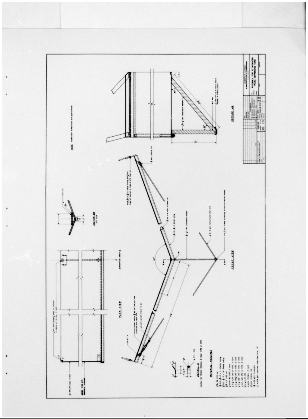
26 wmm MOTE,' Underlined dimensions ore apprmimate. Tom Point -/drill, I holt ' li ttttl bor, 4Zi cut Itngth I righf, I loft roq'i L Hingt out of j 00, fc 10 Sliflby tubing mith pin Hingt pin itcurtd to hingt by it'ö taptr pin ( ) II * UNIVERSITY OF CALIFORNIA SCRIPTS INSTITUTION OF OCtANOGRAPHT tie i Itooci a Kidd SIDE ARM FOR 10' MIDWATER DEPRESSING VANE
Isaacs Kidd Mid water Trawl
 2007 Standard Operating Procedures of Isaacs Kidd Mid water Trawl NAKARET YASOOK APINANT TARADOL TAWEESAK TIMKRUB NARONG REUNGSIVAKUL SOMBOON SIRIRAKSOPHON SOUTHEAST ASIAN FISHERIES DEVELOPMENT CENTER
(fig. 3) must be at the same temperature as the water in this chamber CALORIMETRIC STUDIES OF THE EXTREMITIES
 must be at the same temperature as the water in this chamber CALORIMETRIC STUDIES OF THE EXTREMITIES") CALORIMETRIC STUDIES OF THE EXTREMITIES II. EXPERIMENTAL APPARATUS AND PROCEDURES' By ROY KEGERREIS (Received for publication July 1, 1926) The calorimeter used in these experiments is a modification of
CALORIMETRIC STUDIES OF THE EXTREMITIES II. EXPERIMENTAL APPARATUS AND PROCEDURES' By ROY KEGERREIS (Received for publication July 1, 1926) The calorimeter used in these experiments is a modification of
Interceptors in theory and practice
 Interceptors in theory and practice An interceptor is a small vertical plate, usually located at the trailing edge on the pressure side of a foil. The effect is a completely different pressure distribution
GEAR TECHNOLOGY NOTE - Towed Gear
 GEAR TECHNOLOGY NOTE - Towed Gear This is where the fishing gear is towed through the water to overrun the target species. Main types of towed gear Beam Trawl Demersal Trawl Pelagic Trawl Pair Trawl Pair
PHASE 1 WIND STUDIES REPORT
 PHASE 1 WIND STUDIES REPORT ENVIRONMENTAL STUDIES AND PRELIMINARY DESIGN FOR A SUICIDE DETERRENT SYSTEM Contract 2006-B-17 24 MAY 2007 Golden Gate Bridge Highway and Transportation District Introduction
Cable Grid Testing 2018 Panama City Beach Trawl Diving and TED Testing
 NOAA FISHERIES Cable Grid Testing 2018 Panama City Beach Trawl Diving and TED Testing TIII Evaluation with NEFSC Flounder Trawl TII Evaluation with Kites TI Video Documentation Nicholas Hopkins 7/20/2018
***This summary does not include shad and herring net requirements.***
 South Carolina Department of Natural Resources Marine Resources Division Summary of Seine and Gill Net Laws (Saltwater) 2013-2014 This document should be kept on board all vessels using seines or gill
Technical Briefing Note
 Technical Briefing Note Subject Date Issued Revision Glossary of Terms 14th Nov 2017 Rev 3 The purpose of this Technical Briefing Note is to provide a glossary of terms commonly used in fall injury prevention
WIND CLIPPER KTS ILLUM SCALE INC DEC CLIPPER WIND SYSTEM
 CLIPPER WIND KTS ILLUM SCALE DEC INC CLIPPER WIND SYSTEM TABLE OF CONTENTS INTRODUCTION PRE-TEST OF INSTRUMENT INSTALLING THE MASTHEAD SENSOR UNIT INSTALLING THE DISPLAY NORMAL OPERATION CHANGING THE
DX2/DXX Operating Instructions
 CHECK LINE BY ELECTROMATIC DX2/DXX Operating Instructions CHECK LINE INSTRUMENTS ELECTROMATIC E Q U I P M E N T C O., I N C. 600 Oakland Ave., Cedarhurst, NY 11516 U.S.A. TEL: 516-295-4300 FAX: 516-295-4399
THOR 10 HAMMER CAGE INSTRUCTIONS
 75 " 7m 78 4" m 6" 8.8m 45 ".70m 4.9deg 6 4" 6m 44 4".67m 75 " 7m 9 4" 0m 44".m 497 4".64m The 70, Thor Hammer Cage, consists of four heavy duty aluminum net poles. The unique pole structure reduces the
Beavers are particularly adept at manipulating their
 Beavers are particularly adept at manipulating their environment to suit their needs. They instinctively build dams to raise water levels and increase the area covered by water. Beaver ponds provide security
Presented to the International Technical Rescue Symposium, November Abstract
 Presented to the International Technical Rescue Symposium, November 21 Presented by: Chuck Weber, PMI Quality Manager Abstract This paper presents the results of 162 individual drop tests performed at
(Received 9 September 1940)
") 257 J. Physiol. (I 94I) 99, 257-264 6I2.2II A METHOD OF RECORDING THE RESPIRATION BY J. H. GADDUM From the College of the Pharmaceutical Society, 17 Bloomsbury Square, London, W.C. 2 (Received 9 September
257 J. Physiol. (I 94I) 99, 257-264 6I2.2II A METHOD OF RECORDING THE RESPIRATION BY J. H. GADDUM From the College of the Pharmaceutical Society, 17 Bloomsbury Square, London, W.C. 2 (Received 9 September
river flow. Presented at International Technical Rescue Symposium. 6-8 November, Pueblo, CO. Gordon Smith can be contacted at
 Force on a Highline Caused by River Flow 1 Gordon R. Smith and Stephen R. Allen 2 International Technical Rescue Symposium Pueblo, Colorado, USA November 6-8, 2009 Abstract Seattle Mountain Rescue (SMR)
Ship Resistance and Propulsion Prof. Dr. P. Krishnankutty Ocean Department Indian Institute of Technology, Madras
 Ship Resistance and Propulsion Prof. Dr. P. Krishnankutty Ocean Department Indian Institute of Technology, Madras Lecture - 6 Bulbous Bow on Ship Resistance Welcome back to the class we have been discussing
Sampling Gears and other method. Teerapong Duangdee: Department of Marine Science, Faculty of Fisheries, Kasetsart University
 Sampling Gears and other method Teerapong Duangdee: Department of Marine Science, Faculty of Fisheries, Kasetsart University A) Sampling of fish larvae and eggs from nature Sampling of specimens from nature
Aerodynamic Terms. Angle of attack is the angle between the relative wind and the wing chord line. [Figure 2-2] Leading edge. Upper camber.
![Aerodynamic Terms. Angle of attack is the angle between the relative wind and the wing chord line. [Figure 2-2] Leading edge. Upper camber.](/thumbs/82/86661300.jpg "Aerodynamic Terms. Angle of attack is the angle between the relative wind and the wing chord line. [Figure 2-2] Leading edge. Upper camber.") Chapters 2 and 3 of the Pilot s Handbook of Aeronautical Knowledge (FAA-H-8083-25) apply to powered parachutes and are a prerequisite to reading this book. This chapter will focus on the aerodynamic fundamentals
Chapters 2 and 3 of the Pilot s Handbook of Aeronautical Knowledge (FAA-H-8083-25) apply to powered parachutes and are a prerequisite to reading this book. This chapter will focus on the aerodynamic fundamentals
Falcon 3 145, 170, 195 and Tandem Owner / Service Manual
 Falcon 3 145, 170, 195 and Tandem Owner / Service Manual January 2007 - Second Edition Removing The Sail From The Airframe And Short Packing The Glider Many maintenance and repair procedures will require
5200 Lawrence Place Hyattsville, Maryland 20781, USA Toll Free: Phone: Fax:
 5200 Lawrence Place Hyattsville, Maryland 20781, USA Toll Free: 1-888-416-0174 Phone: 301-277-3888 Fax: 301-277-3323 www.premierkites.com Congratulations on your purchase of the Osprey sport kite. The
For Review Only No Copying No Saving No Lending No Posting Online
 The following copyrighted samples are provided as a service for your review only. Copying, saving, lending, posting online or any general use of these files other than for the purpose provided is unlawful
Description of Underwater Noise Attenuation System Design Unit 2. New NY Bridge Project
 New NY Bridge Project Description of Underwater Noise Attenuation System (NAS) Design Unit 2 Description of Underwater Noise Attenuation System Design Unit 2 for the New NY Bridge Project Revision 1 May
Bottle Rocket Launcher P4-2000
 WWW.ARBORSCI.COM Bottle Rocket Launcher P4-2000 BACKGROUND: The Bottle Rocket Launcher allows for the exploration of launching rockets using commonly available materials such as plastic soda bottles and
List of Figures. List of Tables
 City of Columbia Engineering Regulations PART 19: SPECIFICATIONS FOR FENCING MATERIALS Table of Contents Paragraph Description Page No. 19.1 General 19-1 19.2 Construction Materials 19-1 List of Figures
Introduction. Biological Profile
 Introduction Porcupine Crab (Neolithodes grimaldii) inhabits the sea bed off the Coast of Newfoundland and Labrador in depths beyond 500 fathoms (fm). This large crab is often caught as a by-catch in the
II.E. Airplane Flight Controls
 References: FAA-H-8083-3; FAA-8083-3-25 Objectives Key Elements Elements Schedule Equipment IP s Actions SP s Actions Completion Standards The student should develop knowledge of the elements related to
CHAPTER 4: BEST MANAGEMENT PRACTICES FOR EROSION AND SEDIMENTATION CONTROL
 Figure 4.4m. Type III Floating Turbidity Barrier Source: American Boom and Barrier Corporation and Virginia Department of Transportation (DOT) Standard Sheets 71 4.4.6 Floating Turbidity Barrier Definition
Wind Flow Validation Summary
 IBHS Research Center Validation of Wind Capabilities The Insurance Institute for Business & Home Safety (IBHS) Research Center full-scale test facility provides opportunities to simulate natural wind conditions
Surface Rescue Swimmer School. Primary Rescue Devices and Procedures LT 4.3
 Surface Rescue Swimmer School Primary Rescue Devices and Procedures LT 4.3 2005 1 ENABLING OBJECTIVES Explain the functional operation of the following Rescue Devices per NTTP 3-50.1: 3 Double Rescue Hook
Experimental Analysis on Vortex Tube Refrigerator Using Different Conical Valve Angles
 International Journal of Engineering Research and Development e-issn: 7-067X, p-issn: 7-00X, www.ijerd.com Volume 3, Issue 4 (August ), PP. 33-39 Experimental Analysis on Vortex Tube Refrigerator Using
RESULTS FROM PARACHUTE SEA ANCHOR DRAG TESTS FOR A SPACE CAPSULE, Jan. 10, 2013
 FIORENTINO Technical Report FPA-152 Report Prepared for: America s next generation of spacecraft A spacecraft can be a diameter of 16.5-foot and weigh 18,000 lbs. at splashdown. When the parachute sea
MAKE YOUR OWN SERIES DROGUE. Drogue Kit Instructions downloadable #861310
 MAKE YOUR OWN SERIES DROGUE Drogue Kit Instructions downloadable #861310 Make Your Own Series Drogue 1 Table of Contents Overview 2 Cone Construction 3 Line Preparation 5 Cone Attachment 6 Bridle Attachment
Stevpris installation
 chaser Stevpris deployment for MODUs Introduction Typical methods for deployment and retrieval of Stevpris anchors with an anchor handling vessel (AHV) are described, focusing on the use of chasers for
Applying Hooke s Law to Multiple Bungee Cords. Introduction
 Applying Hooke s Law to Multiple Bungee Cords Introduction Hooke s Law declares that the force exerted on a spring is proportional to the amount of stretch or compression on the spring, is always directed
The Aerodynamic Drag of Parafoils
 The Aerodynamic Drag of Parafoils A. C. Carruthers and A. Filippone The University of Manchester Manchester M60 1QD United Kingdom Introduction The parafoil is an aerodynamic decelerator that uses the
Sprocket Selection Guidelines
 Sprocket Selection Guidelines Table 1 Information Necessary to Order Sprockets 1. Chain Size Number, type, or drawing number of the chain to be used on the sprocket. (The suitability of a sprocket depends
TOLL FREE: SIZING ( )
") Headquarters 915 Oberlin Rd. SW P.O. Box 810 Massillon, OH 44648 Tel: 330-837-4203 Southern Facility 7560 Industrial Highway P.O. Box 10157 Macon, GA 31297 Tel: 478-781-8725 WWW.MIDWESTERNIND.COM TOLL
Headquarters 915 Oberlin Rd. SW P.O. Box 810 Massillon, OH 44648 Tel: 330-837-4203 Southern Facility 7560 Industrial Highway P.O. Box 10157 Macon, GA 31297 Tel: 478-781-8725 WWW.MIDWESTERNIND.COM TOLL
Sourced from:
 Catch Comparison trials using a 400mm Square Mesh Panel Louise Jones SFF Data Analyst Sourced from: http://www.worldfishingtoday.com/newbuildings/default.asp?nyid=621277 Summary: The 400mm SMP alone is
2. Note that the ropes from the rigging board are secured in the cam cleats of the jib fairleads.
 VII 1. Place the hull, bow into wind, on its trailer, a soft surface, or a rigging board. We strongly recommend making a rigging board; it is simple and inexpensive and greatly simplifies rigging and working
Build This World Record Fuselage Model
 Build This World Record Fuselage Model Here You Have Complete Instructions and Plans to Build a Plane of Sure-fire Performance that Established a World Record at the 1932 National Airplane Model Competition
RIGGERS SAFETY SAFETY IS IN THE DETAILS FULL LINE CATALOG
 RIGGERS SAFETY SAFETY IS IN THE DETAILS FULL LINE CATALOG Riggers Safety is a California-based manufacturer of Personal Fall Arrest Systems (PFAS) and Fall Prevention Products. Our automated manufacturing
Best Practice Guidance for Assessing the Financial Performance of Fishing Gear: Industry-led gear trials
 Best Practice Guidance for Assessing the Financial Performance of Fishing Gear: Industry-led gear trials Prepared for The UK Fisheries Economic Network (UKFEN) by Seafish Introduction and Background Reducing
Activities for Measuring Acceleration and Deceleration due to Gravity and Friction. Grade Level: Middle School
 Activities for Measuring Acceleration and Deceleration due to Gravity and Friction Grade Level: Middle School Author: Ron Hurlbut - Illinois Math and Science Academy (rshurl@imsa.edu) Two activities are
Life Cycle Testing of 3x19 Wire Rope
 Life Cycle Testing of 3x19 Wire Rope Shipboard Scientific Support Equipment: Oceanographic Cable NSF Grant No. 0555000 Presented by Rick Trask (WHOI) Topics Results of Bending Fatigue Tests conducted on
Advantage Lockers & Bike
 Advantage Lockers & Bike Advantage Bike Racks & Lockers Inc. is the #1 supplier of Storage Lockers and Bike Racks to the Lower Mainland s residential construction industry. With 25+ years of experience
5200 Lawrence Place Hyattsville, Maryland 20781, USA Toll Free: Phone: Fax:
 5200 Lawrence Place Hyattsville, Maryland 20781, USA Toll Free: 1-888-416-0174 Phone: 301-277-3888 Fax: 301-277-3323 www.premierkites.com Congratulations on your purchase of the Wolf NG sport kite. The
ITTC Recommended Procedures and Guidelines
 Page 1 of 6 Table of Contents 1. PURPOSE...2 2. PARAMETERS...2 2.1 General Considerations...2 3 DESCRIPTION OF PROCEDURE...2 3.1 Model Design and Construction...2 3.2 Measurements...3 3.5 Execution of
Rocket Activity Foam Rocket
 Rocket Activity Foam Rocket Objective Students will learn about rocket stability and trajectory with rubber bandrpowered foam rockets. Description Students will construct rockets made from pipe insulating
GUIDELINES FOR USE GUARD
 GUIDELINES FOR USE GUARD G Guard Range of Load Arrestors Retractable Fall Arrest Safety Line for Protection of Machinery & Sensitive Loads GLOBESTOCK MILE OAK INDUST. ESTATE, MAESBURY ROAD, OSWESTRY, SHROPSHIRE
Preliminary design of a high-altitude kite. A flexible membrane kite section at various wind speeds
 Preliminary design of a high-altitude kite A flexible membrane kite section at various wind speeds This is the third paper in a series that began with one titled A flexible membrane kite section at high
Installation Operation Maintenance
 682 Seal Cooler New generation seal cooler to meet and exceed the seal cooler requirements stated in the 4th Edition of API Standard 682 Installation Operation Maintenance Experience In Motion Description
Trials of a Net Grid for the UK Nephrops trawl fisheries
 Trials of a Net Grid for the UK Nephrops trawl fisheries Tom Catchpole, Frank Armstrong, Stuart Masson, Dave Price, Mark O Brien & John Hingley June 2012 This work was funded by Defra Executive Summary
RIGGERS SAFETY SAFETY IS IN THE DETAILS FULL LINE CATALOG
 RIGGERS SAFETY SAFETY IS IN THE DETAILS FULL LINE CATALOG Riggers Safety is a California-based manufacturer of Personal Fall Arrest Systems (PFAS) and Fall Prevention Products. Our automated manufacturing
Bridge Plugs, Ball Drop & Caged Ball Plugs For Zone Isolation
 Bridge Plugs, Ball Drop & Caged Ball Plugs For Zone Isolation ADVANTAGE composite bridge plug, caged ball and ball drop (flow thru) frac plug provide a means to isolate multiple zones during high pressure
THE BRIDGE COLLAPSED IN NOVEMBER 1940 AFTER 4 MONTHS OF ITS OPENING TO TRAFFIC!
 OUTLINE TACOMA NARROWS BRIDGE FLOW REGIME PAST A CYLINDER VORTEX SHEDDING MODES OF VORTEX SHEDDING PARALLEL & OBLIQUE FLOW PAST A SPHERE AND A CUBE SUMMARY TACOMA NARROWS BRIDGE, USA THE BRIDGE COLLAPSED
Ground Release Shackle
 Operator Manual Subhead Advantages: In the process of installing Slide Rail, the shackle connecting the top of posts, panels, and sheeting must be removed manually. This is normally done by climbing on
Coiled Tubing string Fatigue Management in High Pressure Milling Operation- Case Study
 Coiled Tubing string Fatigue Management in High Pressure Milling Operation- Case Study Abstract: Paper Presenter: Ebrahim Rabbani 1 e.rabbani@mehranservices.com Ebrahim Rabbani, Danial Davoodi 2, Fatemeh
NOTES ON WATER HAMMER. 55
 NOTES ON WATER HAMMER. 55 NOTES ON WATER HAMMER. By A. B. Robison. When the flow conditions of a liquid in a pipe line are varied by the opening or closing of a valve or the equivalent, a change in the
COMPUTATIONAL FLOW MODEL OF WESTFALL'S LEADING TAB FLOW CONDITIONER AGM-09-R-08 Rev. B. By Kimbal A. Hall, PE
 COMPUTATIONAL FLOW MODEL OF WESTFALL'S LEADING TAB FLOW CONDITIONER AGM-09-R-08 Rev. B By Kimbal A. Hall, PE Submitted to: WESTFALL MANUFACTURING COMPANY September 2009 ALDEN RESEARCH LABORATORY, INC.
Chapter 2 Hydrostatics and Control
 Chapter 2 Hydrostatics and Control Abstract A submarine must conform to Archimedes Principle, which states that a body immersed in a fluid has an upward force on it (buoyancy) equal to the weight of the
Installation and Training Manual
 AirForce1 Tower Kit Installation and Training Manual FuturEnergy Limited Ettington Park Business Centre Stratford upon Avon CV37 8BT +44 (0)1789 451070 Table of Contents Safety Notes... 3 Parts Supplied
SAMPLE PAGE. Section 2... Wire Rope
 Section 2...................................................... Wire Rope Never use any kind of clip to directly connect two straight lengths of wire rope to form a continuous piece. Do not make up slings
2016 Physics Olympics Detailed Rules
 2016 Physics Olympics Detailed Rules The UNT Society of Physics Students has hosted their annual Physics Olympics for many years now. Over the years, many teams have competed in a variety of events that
Depth sensor. Product reference : REV 1. USER GUIDE and INSTALLATION GUIDE. nke Sailing competition
 Depth sensor Product reference : 90-60-456 REV 1 USER GUIDE and INSTALLATION GUIDE nke Sailing competition Z.I. Kerandré Rue Gutenberg 56700 HENNEBONT- FRANCE http://www.nke.fr After sale service n 33
Dynamic Positioning Control Augmentation for Jack-up Vessels
 DYNAMIC POSITIONING CONFERENCE October 9-10, 2012 Design and Control Session Dynamic Positioning Control Augmentation for Jack-up Vessels By Bradley Deghuee L-3 Communications 1 Introduction Specialized
Safe Work Practices (SWP) SWP (6) FALL PROTECTION PROGRAM
 SWP (6) FALL PROTECTION PROGRAM") SWP (6) FALL PROTECTION PROGRAM The following information on Fall Protection has been based around the BC OHS Regulations, standards, policies and guidelines. Prior to starting work outside of BC, the
SWP (6) FALL PROTECTION PROGRAM The following information on Fall Protection has been based around the BC OHS Regulations, standards, policies and guidelines. Prior to starting work outside of BC, the
EXERCISE AND INSTRUCTIONS
 TM XPULT EXERCISE AND INSTRUCTIONS Karl Ulrich Christian Terwiesch The Wharton School Department of Operations and Information Management University of Pennsylvania 500 Huntsman Hall Philadelphia, PA 19104
North American sealing solutions Bridge Plug Ball Drop Frac Plug Caged Ball Frac Plug
 North American sealing solutions Bridge Plug Ball Drop Frac Plug Caged Ball Frac Plug The North American Sealing Solutions composite bridge plug, caged ball and ball drop (flow thru) frac plug provide
2 Available: 1390/08/02 Date of returning: 1390/08/17 1. A suction cup is used to support a plate of weight as shown in below Figure. For the conditio
 1. A suction cup is used to support a plate of weight as shown in below Figure. For the conditions shown, determine. 2. A tanker truck carries water, and the cross section of the truck s tank is shown
Manual of Fisheries Survey Methods II: with periodic updates. Chapter 22: Guidelines for Sampling Warmwater Rivers with Rotenone
 Manual of Fisheries Survey Methods II: with periodic updates : Guidelines for Sampling Warmwater Rivers with Rotenone P. W. Seelbach, G. L. Towns, and D. D. Nelson Suggested citation: Seelbach, Paul W.,
Project to Refine a Prototype Unmanned, Tethered ADCP Platform for Measuring Streamflow
 Pagina 1 di 5 Project to Refine a Prototype Unmanned, Tethered ADCP Platform for Measuring Streamflow The use of trade, firm, or product names is for descriptive purposes only and does not imply endorsement
User Instructions 1789 Parapet Wall Anchor
 User Instructions 1789 Parapet Wall Anchor This manual is intended to meet the Manufacturer Instructions as required by ANSI Z359.1 and should be used as part of an employee training program as required
A Portable Vertical Gill-Net System
 INTERNAL REPORT 42 A Portable Vertical Gill-Net System N. W. Bartoo, R. G. Hanson, and R. S. Wydoski September 1972 University of Washington FOR REVIEW ONLY NOT FOR PUBLICATION A PORTABLE VERTICAL GILL-NET
Product Technical Bulletin #48
 AN INTEGRATED SOLUTIONS PROVIDER Product Technical Bulletin #48 Current-Carrying Capacity of R-Series Connectors AirBorn Proprietary Page 1 AN INTEGRATED SOLUTIONS PROVIDER R-Series Current-Carrying Capacity
Wind Energy Technology. What works & what doesn t
 Wind Energy Technology What works & what doesn t Orientation Turbines can be categorized into two overarching classes based on the orientation of the rotor Vertical Axis Horizontal Axis Vertical Axis Turbines
Proof load is the load applied in performance of a proof test. Proof test is a nondestructive tension test performed by the sling manufacturer or an
 1910.184 Slings (a) Scope. This section applies to slings used in conjunction with other material handling equipment for the movement of material by hoisting, in employments covered by this part. The types
Acceleration= Force OVER Mass. Design Considerations for Water-Bottle Rockets
 Acceleration= Force OVER Mass Design Considerations for Water-Bottle Rockets The next few pages are provided to help in the design of your water-bottle rocket. Read through this packet and answer the questions
Marine Kit 4 Marine Kit 4 Sail Smooth, Sail Safe
 Marine Kit 4 Marine Kit 4 Sail Smooth, Sail Safe Includes Basic ship Terminologies and Investigation Check list Index 1. Ship Terminology 03 2. Motions of a Floating Body...09 3. Ship Stability.10 4. Free
NAVIGATOR PROP BUILDING INSTRUCTIONS & PHOTOS
 NAVIGATOR PROP BUILDING INSTRUCTIONS & PHOTOS Science under the ice Ice sheet At regional competitions the ice is simulated by 8 ft x 4 ft ½-inch foam sheeting (Home Depot part #703990 [in store only],
Three different funding sources funded different facets of the research.
 Three different funding sources funded different facets of the research. In November 2014, the research team received monies from the N.C. Marine Fisheries Commission s Conservation Fund, with matching
Figure 1 - Parts Identification. Copyright 2002, DB Industries, Inc.
 User Instruction Manual Zorbit Energy Absorber Kits for Horizontal Lifeline Systems This manual is provided as the Maunfacturer s Instructions, and should be used as part of an employee training program
Field Manual. Simple by Design
 Simple by Design US Patents No. 6,481,300; No. 6,837,120; others pending Field Manual The HydraSleeve is a simple tool. In keeping with the Simple by Design motto, these are the basic instructions. Please
Aquatic Trap Instructions and Information
 Aquatic Trap Instructions and Information Crayfish, Crabs, Shrimp Traps Model 405 Repeating Crayfish Trap featuring trap doors on both ends. Trap doors act as funnels for crayfish to enter. One of the
INSTRUCTION MANUAL. January 23, 2003, Revision 0
 INSTRUCTION MANUAL Model 810A In-Vitro Test Apparatus for 310B Muscle Lever January 23, 2003, Revision 0 Copyright 2003 Aurora Scientific Inc. Aurora Scientific Inc. 360 Industrial Parkway S., Unit 4 Aurora,
6 UNIQUELY DIFFERENT METAL KILLER FISH TRAPS. William Blauser THE EVANS FRYIN PAN TRAP
 6 UNIQUELY DIFFERENT METAL KILLER FISH TRAPS William Blauser The 6 metal, killer fish traps that are the subject of this article are some of the author s favorites that he has collected over the previous
DB Bridge Plug. Features. Benefits. Applications
 DB Bridge Plug The WELLFIRST Premium Cast Iron Bridge Plug designed to run on electric line. Rated between 2000-10000-psi differential, and 300 F from above and below. Features Field Proven Design Constructed
Navigation with Leeway
 Navigation with Leeway Leeway, as we shall use the term, means how much a vessel is pushed downwind of its intended course when navigating in the presence of wind. To varying extents, knowledge of this
Conventional Ship Testing
 Conventional Ship Testing Experimental Methods in Marine Hydrodynamics Lecture in week 34 Chapter 6 in the lecture notes 1 Conventional Ship Testing - Topics: Resistance tests Propeller open water tests
b
 Empirically Derived Breaking Strengths for Basket Hitches and Wrap Three Pull Two Webbing Anchors Thomas Evans a and Aaron Stavens b a Montana State University, Department of Earth Sciences, PO Box 173480,
Physics P201 D. Baxter/R. Heinz
 Seat # Physics P201 D. Baxter/R. Heinz EXAM #1 September 20, 2001 7:00 9:00 PM INSTRUCTIONS 1. Sit in SEAT # given above. 2. DO NOT OPEN THE EXAM UNTIL YOU ARE TOLD TO DO SO. 3. Print your name (last name
Gerald D. Anderson. Education Technical Specialist
 Gerald D. Anderson Education Technical Specialist The factors which influence selection of equipment for a liquid level control loop interact significantly. Analyses of these factors and their interactions
Fall Protection Refresher Orientation. Fall Protection Refresher Orientation 1
 Fall Protection Refresher Orientation Fall Protection Refresher Orientation 1 Course Objectives! Understand the definitions of fall prevention, fall restraint, and fall arrest.! Understand the requirements
Model A Sleeve Valve Cement Retainer
 Ret. O.D. Model A Sleeve Valve Cement Retainer DIMENSIONAL DATA A B C D E F G H J K L M N P Q R 3.593 3.593 3.500 2.500 3.531 3.531 1.345 3.375.750.437 2.437 2.187 7.062 2.437 5.312 11.685 20.093 3.937
The Holding Power of Anchors
 The Holding Power of Anchors G 1 Taylor The essential principle in the action of all anchors is that a surface set at an acute angle to the ground will dig in if pulled horizontally. In order that an anchor
It should be noted that the symmetrical airfoil at zero lift has no pitching moment about the aerodynamic center because the upper and
 NAVWEPS -81-8 and high power, the dynamic pressure in the shaded area can be much greater than the free stream and this causes considerably greater lift than at zero thrust. At high power conditions the
HCMTCB MATERIALS SAMPLING & TESTING PERFORMANCE CHECKLIST
 HCMTCB MATERIALS SAMPLING & TESTING PERFORMANCE CHECKLIST Release Date: January 7, 2014 Sampling Coarse Aggregate PERFORMANCE CHECKLIST AASHTO T-2 Sampling of Aggregates Sampling From A Stockpile 1 When
CTB3365x Introduction to Water Treatment
 CTB3365x Introduction to Water Treatment D4b Aeration Doris van Halem Did you know that there are not just gasses in your glass of sparkling coke, but also in the tap water you drink? Welcome to the water
The author's TD Coupe, used as a towplane, and the Airhopper. The gas model is equipped with an automatic towline release.
 THE AIRHOPPER BY STANLEY ORZECK PLANS BY PAUL PLECAN An eight-foot sailplane either towed by a gas model or launched by hand tow. The author's TD Coupe, used as a towplane, and the Airhopper. The gas model
2010 International Snow Science Workshop
 HOW TO TURN A KIDS BIKE INTO A BOMB TRAM FOR AVALANCHE CONTROL WORK David Immeker* Heavenly Mountain Resort Professional Ski Patrol, South Lake Tahoe, California ABSTRACT: Bomb trams have been used for
Draft Indian Standard SAFES Part 2 Tests for Burglary Resistance (Fifth Revision)
") Draft For Comments Only Draft Indian Standard SAFES Part 2 Tests for Burglary Resistance (Fifth Revision) Not to be reproduced without the permission of Last date for receipt of BIS or used as a STANDARD
Draft For Comments Only Draft Indian Standard SAFES Part 2 Tests for Burglary Resistance (Fifth Revision) Not to be reproduced without the permission of Last date for receipt of BIS or used as a STANDARD