Users Group Conference 2018
|
|
|
- Nickolas Taylor
- 5 years ago
- Views:
Transcription
1 Users Group Conference 2018 Compressor Analysis Special Circumstances Tracy Wimberly Sr. Reciprocating Equipment Analyst, Windrock 1

2 Topics, top compressor questions Ultrasound Baseline Cat Eyes Leak Index VE Correction Toe Pressure and Slope Checks TDC Raw Sensor Points Backups Theoretical PV Models Clearance Calculation Models 2
3 Ultrasound Traces, how about some definition to the baselines 3
4 The Problem with a flat baseline? Leakage pattern may be missed. A flat line could indicate the gain was too low. Increasing the scale with a flat line baseline will sometimes only display a larger flat line. Stacking ult traces on a group plot will shrink the scale 4
5 Increase the Gain Increasing the gain may clip the peaks of the valve opening and closing. Clipping the peaks of the acoustic response is ok because it is not measuring the impacting of the valve opening or closing. 5
6 Valve Leaks While It Is Closed Some ultrasound traces can be very noisy in this area. The tapering of the baseline during compression and expansion can sometimes help detect leakage 6
7 Cat Eyes Named from the ultrasound pattern it can make on a PT/VT plot Can look like two cat eyes on the PT Acoustic response from gas passing by the rings Occurs at pressure reversal Quiet area Sometimes it is the only indicator of damage to the piston rings Best seen if collected on cylinder ends but can be seen on valve cap ultrasounds sensor points 7

8 Cat Eyes, with and without 8

9 Leak Index, making MD work for you! Leak Index is the indexing of the compression and expansion lines on the PV at the similar pressures The points created from the indexing will generate a curve If the compression line and expansion line do not have leakage then the curve will be a straight and flat line 9

10 Leak Index With Suction Leakage Suction leakage will cause the straight flat line to rise past zero on the left side and fall past zero on the right side The percentage number is an indicator of severity It is the percentage the line is off of zero 10

11 Leak Index With Discharge Leakage Discharge leakage will cause the straight flat line to fall past zero on the left side and rise past zero on the right side The percentage number is an indicator of severity It is the percentage the line is off of zero 11

12 Leak Index With Piston Ring Leakage Piston Ring leakage will cause a curved (hooked) line to rise past zero on the left side and fall past zero on the right side The percentage number is an indicator of severity for suction leakage It is the percentage the line is off of zero 12
13 Leak Index Diagnostics The Leak Index is how MD will make suction, discharge and piston ring leakage diagnostic calls Due to a very high number variables the analyst has to careful control three aspects of the Leak Index Smoothing of the Leak Index curve The percentage of the compression and expansion line it uses to make the curve The sensitivity of the warnings and alarms 13

14 Leak Index Software Options These changes can be made under the software setup tab High speed units will need up to 14 for smoothing Window is % away from the toe pressure 14
15 VE Correction, Rules to the Nuclear Option I call it the nuclear option because it is the last thing you should do when you are validating your data VE Correction can affect the integrity of the data VE Correction is for adjusting toe pressure, compensating for skinny VEs and adjusting VEs due to pulsation and inaccurate compression/expansion picks Channel Resonance Restriction between transducer and internal cylinder pressure High Speed delay 15
16 Rule #1, stay on the slope The slope of the compression and expansion line needs to be followed If pulsation has physically moved the line of the slope then you should follow where the slope should be 16
17 Rule #2, stay on the toe The toe pressure at 0 and 100% swept volume in some cases may cover a wide range of pressure Try to follow it to the opposite side and use both pressures 17
18 Rule #3, Check yourself before you The calculator and adjust clearance windows should be brought up at the same time you are moving the VEs This allows you to check to see if the data is making sense with flow balance and the suction\discharge clearance calculations Previous data, slopes of the theoretical compression and expansion and panel suction and discharge pressure are just a few things you can use 18

19 VE Corrected! 19
20 Toe Pressure and Slope Checks Toe and slope checks can be used to check for the correct theoretical model, the correct clearance and for general data validation and comparison The slope as a whole will typically be more accurate than the toe pressure 20

21 Equation of State (K) vs N Base, Top is K and bottom is N Base 21
22 Smooth Less & Adjust Toes, top CE suction toe pressure slightly high 22

23 Lessons Learn VE being moved can shift/control the theoretical compression or expansion line on the opposite side of the PV If you move the VE then you need to adjust clearances Some bugs still remain, Windrock is working them 23
24 TDC, the three big indicators Flow Balance Are all of the Flow Balances above 1 or below it? Leak Index How flat is the Leak Index Adjust Clearance Window The difference between the calculated suction and calculated discharge 24
25 TDC Confirmation Pitfalls Unhealthy cylinders Too much smoothing May have to stop smoothing significantly before yellow indicator All cylinder s data should make sense with the new TDC Must be able to explain why the indicators are abnormal Bad geometry and/or gas analysis Wrong models Bad data Restriction and high speed delay 25

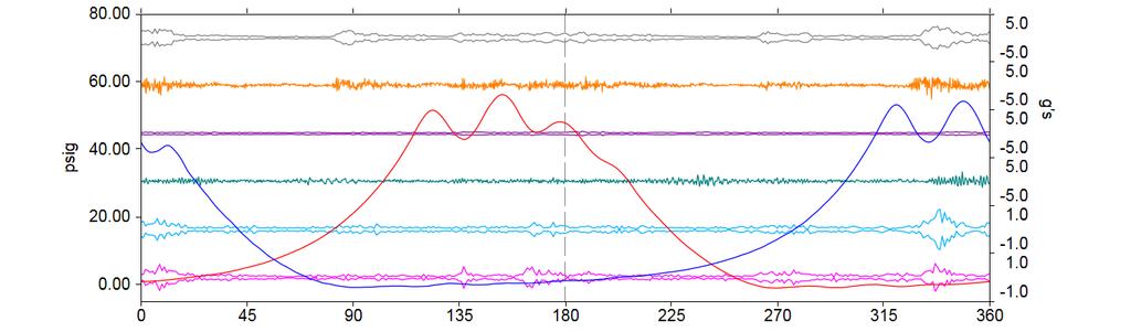
26 TDC -10 Degrees, note discharge toe pressure 26

27 TDC +10 Degrees, note discharge toe pressure 27

28 Correct TDC 28
29 Raw Sensor Points Backups It has come to my attention that some Raw vibration sensor points, in special circumstances, are not displaying vibration impacts normally The reason appears to be from modulated vibration Modulated impacts will make data interpretation difficult because it muffles the impacts Modulated vibration signatures have only been documented in a few cases These cases have been documented with setups that the user had used 4 samples per degree with medium to high speed compressors/engines. 29
30 Why is modulation a problem? Pattern interpretation is one of the 3 major techniques used for analysis Slight differences like sharp points and a few degrees can be the difference between identifying a problem or missing it. 30
31 FFT to back it up I am recommending adding a FFT acceleration sensor point to backup every Raw sensor point This is not for the FFT plot but to compare the time waveform to the Raw sensor point A Raw sensor point looks at 30 to 600,000 CPM Here is the setup I would recommend Accelerometer with the units displayed in Gs and peak. The sensitivity still at 100 and the auto box checked. The source will be standard. Channel 1 is used. The averages should be about lines, Hanning window and Fmax is at 600,000 CPM. Mode will be Linear + and TDC should also be selected. Setup would be very similar to a Raw sensor point but sampling less so less likely to have modulation 31
32 The Comparison, top is Raw and bottom is time waveform Bailey C-202 Compressor Comp Mn Brg 4 Accel Run 1 Time Waveform at RPM 04/17/ gs Time (milliseconds) 32
33 Navigating in WinTrans Click on FFT icon in MD Click on the Point Selection icon in WinTrans Make sure to change the plot from FFT to time waveform Scroll through the list and find the correct sensor point The time waveform length will be too long to see impacts Right key click on plot to adjust X axis Change to number to about milliseconds, so that only a few dotted line are in the time waveform Dotted lines are TDC marks 33
34 Other Things Reducing your Raw sensor points to 2 samples per degree with medium and high speed units Using the flat magnet in place of the rail magnet for Raw sensor points Both of these things are to reduce the mounting resonance frequency vibration which may play a part in the possible issue. Document all cases with major discrepancies between the Raw and acceleration time waveforms sensor points 34
35 Theoretical PV Models Windrock offers 4 theoretical PV models Specific Heats (Equation of State Model K Temperature) K Based (Adiabatic) N Based Averaged N Based The Specific Heats is the default and the most widely used 35
36 Facts Jack You don t need to know your compressor s thermodynamic process but the more you understand them the better your analysis will be Isothermal, Adiabatic or Polytrophic All compressors have variations of all of these thermodynamic processes and they can change Liquids dropping out, water jackets plugged up, significant gas makeup change and ambient heating or just a few things that can modify the thermodynamic process You do have to know which theoretical model will work best for your data 36
37 So Which One Do I Use? The answer is that you use the one that gives you the best results Theoretical model lines up with the actual data Has the best analysis capabilities Purpose is to see leakage An accurate gas analysis, good data and the correct geometry will make the Equation of State Model K Temperature model work well enough to do your analysis on most compressors 37
38 What Makes The Models Tic? The models are based off of the actual PV data K base models use the gas analysis N base models do not use gas analysis Bad gas analysis Gas composition changes frequently like flare gas units Gas behaves differently at high pressures like CO2 All of them use the set clearance to a degree Models do not change the slope of the compression and expansion, they change the VE which changes the slopes 38
39 The Down Side to N Based PV pattern interpretation of a leaking cylinder will change Some cases leakage that can be easily seen with K based models will not show up at all using the N models N based models force the model to fit the PV at the VE area Leakage can only be seen between the toes if it can be seen at all Should not use N models to set clearances And the Bug If N base models are used then changing the group plots will only show K base models unless you make it calculate. You can make it calculate by toggling the VE adjustment or Theoretical icon. However, changing the group plot will make it start over again. 39
40 Example #1 (Short & Fat PV) 40
41 Example #2 (Medium and Average) 41
42 Example #3 (Tall and Skinny PV) 42
43 The Point N Base Theoretical will bend your theoretical PV in way which you will not see valve leakage Leaking piston rings can still be seen because of the curve 43
44 That s A Plus The N Base Theoretical model Nonlinear curve from piston ring leakage will show up Can be used to verify gas analysis Can be used to verify TDC with compressor where the K base models fall short Can be used to finally make that theoretical model fit that PV. (For show only) 44
45 Average N Base To The Rescue The point to the Average N Base model is for the benefits of the N Base model but to still see that valve leakage Works just like the N Base model but the VE placement is average out so you can see the valve leakage The correct clearance calculation is critical However, if you are using the Adjust Clearance Window, the Average Clearance method or doing any verification then you should change your model to the specific heats model until the verification is completed and clearances are set It can exaggerate valve leakage (just like the average K) 45
46 Example #1 (Short and Fat PV), top is K and bottom is Average N 46
47 Example #2 (Medium and Average) bottom is the average N 47
48 Example #3 (Tall and Skinny PV), bottom is average N 48
49 Sum It Up Try to use the specific heats model Definitely use it to do most of your validation and to set clearances If you have a good gas analysis and the specific heats model is not showing valve leakage well then try the K Average If your gas analysis is suspect or the gas is constantly changing then try the N Average Watch out for late closing valves Windrock software does not know how to handle it Can affect TDC validation and clearance validation which is a domino effect 49
50 Clearance Calculation Models Windrock offers 2 models GPSA Calculations from the GPSA Engineering Data Book Calculations include the ratio of the suction Z value to the discharge Z value a based Calculations from the Southwest Research Institute s Technical Report 84-10a. Calculations do not include Z ratio. However, K valves are used Works well in cases of unusual compression like CO2 50


51 How Does It Work On CO2? 84-10a is bottom 51
52 Which One Should I Use? Before deciding which calculation to use Validate TDC, data and temperatures Choose the highest pressure cylinder that does not have leakage or need much VE Correction VERIFY that valves are not closing late and no piston rings are leaking Turn Smoothing down the lowest setting you can without significantly changing the toe pressure or the slopes. Use both methods Watch how the average moves the theoretical towards or away from the PV 52

53 Magic, GPSA was the winner! Time for the icing on the cake. 53

54 Thank You 54
June By The Numbers. Compressor Performance 1 PROPRIETARY
 June 15 2016 By The Numbers Compressor Performance 1 PROPRIETARY Compressor Performance Report Without an accurate TDC, the report information has no value! 2 PROPRIETARY Compressor Performance Report
ASK THE EXPERTS: The Characteristics and Applications of the Ultrasonic Sensor (Part 1 Compressors)
") June 2016 ASK THE EXPERTS: The Characteristics and Applications of the Ultrasonic Sensor (Part 1 Compressors) QUESTION: I recently had start-up assistance training on my Windrock analyzer. What are some
June 2016 ASK THE EXPERTS: The Characteristics and Applications of the Ultrasonic Sensor (Part 1 Compressors) QUESTION: I recently had start-up assistance training on my Windrock analyzer. What are some
Economic Benefits Of Compressor Analysis >
 Economic Benefits Of Compressor Analysis > Improving gas flow through a compressor maximizes value and revenue By EDWARD B. FLANAGAN, PE Edward B. Flanagan, PE, is the general manager at Windrock Inc.
Lab 1. Adiabatic and reversible compression of a gas
 Lab 1. Adiabatic and reversible compression of a gas Introduction The initial and final states of an adiabatic and reversible volume change of an ideal gas can be determined by the First Law of Thermodynamics
Sizing Pulsation Dampeners Is Critical to Effectiveness
 Sizing Pulsation Dampeners Is Critical to Effectiveness Pressure variation is an important consideration when determining the appropriate size pulsation dampener needed for an application. by David McComb,
Acoustical Modeling of Reciprocating Compressors With Stepless Valve Unloaders
 Acoustical Modeling of Reciprocating Compressors With Stepless Valve Unloaders Kelly Eberle, P.Eng. Principal Engineer keberle@betamachinery.com Brian C. Howes, M.Sc., P.Eng. Chief Engineer bhowes@betamachinery.com
Compressors. Basic Classification and design overview
 Compressors Basic Classification and design overview What are compressors? Compressors are mechanical devices that compresses gases. It is widely used in industries and has various applications How they
HKA TECHNOLOGIES INC. TEMPERATURE COMPENSATION
 HKA TECHNOLOGIES INC. TEMPERATURE COMPENSATION Different Methods of Air Leak Testing Conventional vs Bell Jar Pressure Decay and Differential Pressure Decay Mass Flow and Differential Mass Flow HKA mainly
Analytic and Experimental Techniques for Evaluating Compressor Performance Losses
 Purdue University Purdue e-pubs International Compressor Engineering Conference School of Mechanical Engineering 1976 Analytic and Experimental Techniques for Evaluating Compressor Performance Losses J.
Chromat Calibration Updated October 27th, 2017
 Chromat Calibration Updated October 27th, 2017 Calibrating the Chromatograph Performing the Chromat Calibration is highly recommended when starting a new well. The MLogger already has a default calibration
Lab #12:Boyle s Law, Dec. 20, 2016 Pressure-Volume Relationship in Gases
 Chemistry Unit 6:States of Matter & Basic Gas Laws Name Lab Partner Lab #12:Boyle s Law, Dec. 20, 2016 Pressure-Volume Relationship in Gases Purpose: The primary objective of this experiment is to determine
Boyle s Law: Pressure-Volume Relationship in Gases
 Boyle s Law: Pressure-Volume Relationship in Gases The primary objective of this experiment is to determine the relationship between the pressure and volume of a confined gas. The gas we will use is air,
Smart maintenance by using data analytics during industry 4.0. By Dr. TRINATH SAHOO
 Smart maintenance by using data analytics during industry 4.0 By Dr. TRINATH SAHOO What will be discussed Industry 4.0 concept. what is data analytics. Use of data analytics for machine prognosis. Question
67. Sectional normalization and recognization on the PV-Diagram of reciprocating compressor
 67. Sectional normalization and recognization on the PV-Diagram of reciprocating compressor Jin-dong Wang 1, Yi-qi Gao 2, Hai-yang Zhao 3, Rui Cong 4 School of Mechanical Science and Engineering, Northeast
Schedule of Requirements THERMODYNAMICS LABORATORY- CHEMICAL ENGINEERING DEPARTMENT
 S. No 1 Description Calorimeter The Unit should be designed for the accurate determination of the calorific value of liquid and solid hydrocarbons and other fuels. Specifications: A temperature-controlled
Specifications and information are subject to change without notice. Up-to-date address information is available on our website.
 www.smar.com Specifications and information are subject to change without notice. Up-to-date address information is available on our website. web: www.smar.com/contactus.asp LD302 - AssetView HMI LD302
Noise Characteristics Of A Check Valve Installed In R22 And R410A Scroll Compressors
 Purdue University Purdue e-pubs International Compressor Engineering Conference School of Mechanical Engineering 22 Noise Characteristics Of A Check Valve Installed In R22 And R41A Scroll Compressors M.
GLOSSARY OF TERMS. Adiabatic Compression Compression process when all heat of compression is retained in the gas being compressed.
 GLOSSARY OF TERMS Absolute pressure Total pressure measured from absolute zero i.e. a perfect vacuum. As a practical matter, gauge pressure plus atmospheric pressure. Absolute temperature Temperature measured
Sontek RiverSurveyor Test Plan Prepared by David S. Mueller, OSW February 20, 2004
 Sontek RiverSurveyor Test Plan Prepared by David S. Mueller, OSW February 20, 2004 INTRODUCTION Sontek/YSI has introduced new firmware and software for their RiverSurveyor product line. Firmware changes
Vibration Related Failures of Small-Bore Attachments
 Vibration Related Failures of Small-Bore Attachments Brian C. Howes, M.Sc., P.Eng Chief Engineer bhowes@betamachinery.com Chris B. Harper, P.Eng Project Engineer charper@betamachinery.com Beta Machinery
Pressure Indication of Twin Screw Compressor
 Purdue University Purdue e-pubs nternational Compressor Engineering Conference School of Mechanical Engineering 1990 Pressure ndication of Twin Screw Compressor K. Haugland The Norwegian nstitute of Technology
Please welcome for any correction or misprint in the entire manuscript and your valuable suggestions kindly mail us
 Problems of Practices Of Basic and Applied Thermodynamics First Law of Thermodynamics Prepared By Brij Bhooshan Asst. Professor B. S. A. College of Engg. And Technology Mathura, Uttar Pradesh, (India)
Boyle s Law. Pressure-Volume Relationship in Gases. Figure 1
 Boyle s Law Pressure-Volume Relationship in Gases The primary objective of this experiment is to determine the relationship between the pressure and volume of a confined gas. The gas we use will be air,
INDIAN INSTITUTE OF TECHNOLOGY ROORKEE NPTEL NPTEL ONLINE CERTIFICATION COURSE. Refrigeration and Air-conditioning
 INDIAN INSTITUTE OF TECHNOLOGY ROORKEE NPTEL NPTEL ONLINE CERTIFICATION COURSE Refrigeration and Air-conditioning Lecture-07 Vapour Compression Cycle-1 with Prof. Ravi Kumar Department of Mechanical and
The University of Hong Kong Department of Physics Experimental Physics Laboratory
 The University of Hong Kong Department of Physics Experimental Physics Laboratory PHYS2260 Heat and Waves 2260-1 LABORATORY MANUAL Experiment 1: Adiabatic Gas Law Part A. Ideal Gas Law Equipment Required:
Boyle s Law: Pressure-Volume Relationship in Gases. PRELAB QUESTIONS (Answer on your own notebook paper)
") Boyle s Law: Pressure-Volume Relationship in Gases Experiment 18 GRADE LEVEL INDICATORS Construct, interpret and apply physical and conceptual models that represent or explain systems, objects, events
Boyle s Law: Pressure-Volume Relationship in Gases Experiment 18 GRADE LEVEL INDICATORS Construct, interpret and apply physical and conceptual models that represent or explain systems, objects, events
The benefits of the extended diagnostics feature. Compact, well-proven, and flexible
 ABB MEASUREMENT & ANALYTICS TECHNICAL INFORMATION PositionMaster EDP300 Extended Diagnostics Compact, well-proven, and flexible The benefits of the extended diagnostics feature The PositionMaster EDP300
Experiment 11: The Ideal Gas Law
 Experiment 11: The Ideal Gas Law The behavior of an ideal gas is described by its equation of state, PV = nrt. You will look at two special cases of this. Part 1: Determination of Absolute Zero. You will
A Numerical Simulation of Fluid-Structure Interaction for Refrigerator Compressors Suction and Exhaust System Performance Analysis
 1131, Page 1 A Numerical Simulation of Fluid-Structure Interaction for Refrigerator Compressors Suction and Exhaust System Performance Analysis Shoufei Wu*, Zonghuai Wang Jiaxipera Compressor Co., Ltd.,
Boyle s Law: Pressure-Volume. Relationship in Gases
 Boyle s Law: Pressure-Volume Relationship in Gases The primary objective of this experiment is to determine the relationship between the pressure and volume of a confined gas. The gas we use will be air,
Performance Monitoring Examples Monitor, Analyze, Optimize
 Performance Monitoring Examples Monitor, Analyze, Optimize BETA's Performance Assessment service is a low cost remote monitoring service for reciprocating compressors, centrifugal compressors, engines,
Characterizers for control loops
 Characterizers for control loops By: F. G. Shinskey (May 1999) Introduction Commercial controllers such as the PID series (proportional, integral, derivative, and their combinations) are linear devices
Offshore Equipment. Yutaek Seo
 Offshore Equipment Yutaek Seo Flash Gas Compressor (East spar) Dehydration NGL recovery Slug catcher Separator Stabilization Booster compressor Gas export compression (Donghae-1 Platform) May 7 th Gas
ME1251 THERMAL ENGINEERING UNIT IV AIR COMPRESSORS
 ME1251 THERMAL ENGINEERING UNIT IV AIR COMPRESSORS UNIT-IV 4. 1 CONTENTS TECHNICAL TERMS 4.1 Classification of compressors 4.2 Positive Displacement compressors 4.2.1 Double acting compressor 4.2.2 Diaphragm
CFD Simulation and Experimental Validation of a Diaphragm Pressure Wave Generator
 CFD Simulation and Experimental Validation of a Diaphragm Pressure Wave Generator T. Huang 1, A. Caughley 2, R. Young 2 and V. Chamritski 1 1 HTS-110 Ltd Lower Hutt, New Zealand 2 Industrial Research Ltd
Specifications and information are subject to change without notice. Up-to-date address information is available on our website.
 www.smar.com Specifications and information are subject to change without notice. Up-to-date address information is available on our website. web: www.smar.com/contactus.asp FY302 AssetView IHM FY302 -
LABORATORY EXERCISE 1 CONTROL VALVE CHARACTERISTICS
 Date: Name: LABORATORY EXERCISE 1 CONTROL VALVE CHARACTERISTICS OBJECTIVE: To demonstrate the relation between valve stem position and the fluid flow through a control valve, for both linear and equal
The Estimation Of Compressor Performance Using A Theoretical Analysis Of The Gas Flow Through the Muffler Combined With Valve Motion
 Purdue University Purdue e-pubs International Compressor Engineering Conference School of Mechanical Engineering The Estimation Of Compressor Performance Using A Theoretical Analysis Of The Gas Flow Through
Lab 1c Isentropic Blow-down Process and Discharge Coefficient
 058:080 Experimental Engineering Lab 1c Isentropic Blow-down Process and Discharge Coefficient OBJECTIVES - To study the transient discharge of a rigid pressurized tank; To determine the discharge coefficients
Vibration Analysis and Test of Backup Roll in Temper Mill
 Sensors & Transducers 2013 by IFSA http://www.sensorsportal.com Vibration Analysis and Test of Backup Roll in Temper Mill Yuanmin Xie College of Machinery and Automation, Wuhan University of Science and
Boyle s Law: Pressure-Volume Relationship in Gases
 Boyle s Law: Pressure-Volume Relationship in Gases Experiment The primary objective of this experiment is to determine the relationship between the pressure and volume of a confined gas. The gas we use
Truck-mounted Mass Flow Metering for LPG Delivery
 Truck-mounted Mass Flow Metering for LPG Delivery Itron, Inc. 1310 Emerald Rd. Greenwood, SC 29646 Introduction The mathematician Gustave De Coriolis first described the Coriolis Effect, which is an inertial
REACTOR 40 MECHANICAL Configuration Guide
 REACTOR 40 MECHANICAL Configuration Guide Important Safety Information WARNING See the Important Safety and Product Information guide in the product box for product warnings and other important information.
Oil-Lubricated Compressors for Regenerative Cryocoolers Using an Elastic Membrane
 Oil-Lubricated Compressors for Regenerative Cryocoolers Using an Elastic Membrane E.C. Luo, Z.H. Wu, G.Y. Yu, J.Y. Hu, and W. Dai Technical Institute of Physics and Chemistry Chinese Academy of Sciences
Using PV Diagram Synchronized With the Valve Functioning to Increase the Efficiency on the Reciprocating Hermetic Compressors
 Purdue University Purdue e-pubs International Compressor Engineering Conference School of Mechanical Engineering 21 Using PV Diagram Synchronized With the Valve Functioning to Increase the Efficiency on
Standard HRiM Editing Techniques
 Standard HRiM Editing Techniques Opening the Study: Double click on the Sandhill Applications icon on the desktop. Click 'Analysis'. Click 'Select Patient': The path to find the patient file is: C:\Sandhill\Patients\EFT
OPTIMA 7 - BIOGAS Calibrating the gas sensors SENSOR ADJUSTMENT. Diamond Scientific 625 Peachtree St., Cocoa, Florida /Tel:
 SENSOR ADJUSTMENT The calibration of your OPTIMA 7 should be performed by experienced service personal only! MRU will not be responsible for any misuse or wrong interpretation of this calibration instruction.
PositionMaster EDP300 Extended Diagnostics. Compact, well-proven, and flexible
 Change from one to two columns Technical Information TI/EDP300_ED-EN Rev. A PositionMaster EDP300 Extended Diagnostics Compact, well-proven, and flexible The benefits of the extended diagnostics feature
Earlier Lecture. In the earlier lecture, we have seen Kapitza & Heylandt systems which are the modifications of the Claude System.
 17 1 Earlier Lecture In the earlier lecture, we have seen Kapitza & Heylandt systems which are the modifications of the Claude System. Collins system is an extension of the Claude system to reach lower
ACV-10 Automatic Control Valve
 ACV-10 Automatic Control Valve Installation, Operation & Maintenance General: The Archer Instruments ACV-10 is a precision automatic feed rate control valve for use in vacuum systems feeding Chlorine,
CONTROL VALVE WHAT YOU NEED TO LEARN?
 CONTROL VALVE WHAT YOU NEED TO LEARN? i) The control valve characteristics refers to the relationship between the volumetric flowrate F (Y-axis) through the valve AND the valve travel or opening position
Name Student Activity
 Open the TI-Nspire document Boyles_Law.tns. In this activity, you will use a Gas Pressure Sensor to measure the pressure of an air sample inside a syringe. Using graphs, you will apply your results to
RICK FAUSEL, BUSINESS DEVELOPMENT ENGINEER TURBOMACHINERY CONTROL SYSTEM DESIGN OBJECTIVES
 RICK FAUL, BUSINESS DEVELOPMENT ENGINEER TURBOMACHINERY CONTROL SYSTEM DESIGN OBJECTIVES The primary design objective for any turbomachinery control system should be to maintain or maximize machine and
Boyle s Law: Pressure-Volume Relationship in Gases
 Boyle s Law: Pressure-Volume Relationship in Gases Computer 6 The primary objective of this experiment is to determine the relationship between the pressure and volume of a confined gas. The gas we use
Manual for continuous distillation
 Manual for continuous distillation 1. Week 1: Objectives: Run the column at total reflux. When steady state is reached, take the sample from the top and bottom of the column in order to determine the overall
The Gas Laws: Boyle's Law and Charles Law
 Exercise 6 Page 1 Illinois Central College CHEMISTRY 130 Name The Gas Laws: Boyle's Law and Charles Law Objective The simple laws governing the properties of gases can be readily demonstrated experimentally.
Simulator For Performance Prediction Of Reciprocating Compressor Considering Various Losses
 Simulator For Performance Prediction Of Reciprocating Considering Various Losses Aditya S. Bawane 1, Dr. V.K. Bhojwani 2, Mitali B. Deshmukh 3 1 (Mechanical Engineering Department, JSCOE, S.P. Pune University,
Heat Engine. Reading: Appropriate sections for first, second law of thermodynamics, and PV diagrams.
 Heat Engine Equipment: Capstone, 2 large glass beakers (one for ice water, the other for boiling water), temperature sensor, pressure sensor, rotary motion sensor, meter stick, calipers, set of weights,
Reciprocating Compressor Diagnostics, Detecting Abnormal Conditions from Measured Indicator Cards
 Purdue University Purdue e-pubs nternational Compressor Engineering Conference School of Mechanical Engineering 1996 Reciprocating Compressor Diagnostics, Detecting Abnormal Conditions from Measured ndicator
ME-GI. MAN Diesel & Turbo. ME-GI Design, June 2012 Presentation for Croatian Register, 30 th August MAN Diesel & Turbo JNA/LDE
 2012 ME-GI MAN Diesel & Turbo ME-GI Design, June 2012 Presentation for Croatian Register, 30 th August 2012 1 Presentation Gas injection system Principles Control system, control system components Combustion
Unit 24: Applications of Pneumatics and Hydraulics
 Unit 24: Applications of Pneumatics and Hydraulics Unit code: J/601/1496 QCF level: 4 Credit value: 15 OUTCOME 2 TUTORIAL 9 ACCUMULATORS The material needed for outcome 2 is very extensive so there are
Air Displacement Pipetting Modules. Total Integrated Liquid Handling
 Air Displacement Pipetting Modules Total Integrated Liquid Handling Intelligent Liquid Handling For Better Results MOVING LIQUID IS EASY; PRECISION LIQUID HANDLING IS HARD Instrument manufacturers frequently
MIL-STD-883G METHOD
 STEADY-STATE LIFE 1. PURPOSE. The steady-state life test is performed for the purpose of demonstrating the quality or reliability of devices subjected to the specified conditions over an extended time
Application Note AN-107
 SPEC Sensor TM Characterization & Calibration Considerations Scope This document is provided to describe the considerations needed to characterize, calibrate, verify and validate the measurement performance
Compiled by: B Beard. Approved by: SH Carstens. Description of requirements and procedures for compact provers to be used as verification standards.
 1. Scope Description of requirements and procedures for compact provers to be used as verification standards. 2. Reference documents Trade Metrology Act SANS1698 3. Policy A. BASIC REQUIREMENTS Compact
Incorporating 3D Suction or Discharge Plenum Geometry into a 1D Compressor Simulation Program to Calculate Compressor Pulsations
 Purdue University Purdue e-pubs International Compressor Engineering Conference School of Mechanical Engineering 2012 Incorporating 3D Suction or Discharge Plenum Geometry into a 1D Compressor Simulation
#LZ400 LEAKALYZER. Water Loss Sensor INSTRUCTION MANUAL Country Dr. #190 St. Paul, MN
 #LZ400 LEAKALYZER Water Loss Sensor INSTRUCTION MANUAL 2885 Country Dr. #190 St. Paul, MN 55117 800-348-1316 www.leaktools.com Your Partner in Swimming Pool Water Conservation Product Purpose: 2 The Leakalyzer
Touch Screen Guide. OG-1500 and OG Part # T011
 Touch Screen Guide OG-1500 and OG-2000 Part # 9000000.T011 Effective 11/2010 External View Internal View 1. Transducer Banks 2. Oxygen Sensor 3. PLC These are the two manifolds with three (3) transducers
Development of a High Pressure, Oil Free, Rolling Piston Compressor
 Purdue University Purdue e-pubs International Compressor Engineering Conference School of Mechanical Engineering 1994 Development of a High Pressure, Oil Free, Rolling Piston Compressor S. J. Delmotte
GCMSD-Headspace Analysis SOP
 Before you start GCMSD-Headspace Analysis SOP Method and Sequences names are restricted to 50 characters (MSD program will crash otherwise) The GC oven and Injection Ports need to be cooled to 50 oc to
AN ANALYSIS ON HIGH PRESSURE DYNAMIC CALIBRATORS USED IN THE DEFENSE AREAS
 AN ANALYSIS ON HIGH PRESSURE DYNAMIC CALIBRATORS USED IN THE DEFENSE AREAS Sung Soo HongPresenter Agency for Defense Development, Taean, 357-942, South Korea sungsoo@add.re.kr Abstract Up to now, there
Capacity Modulation of Linear Compressor for Household Refrigerator
 Purdue University Purdue e-pubs International Compressor Engineering Conference School of Mechanical Engineering 2004 Capacity Modulation of Linear Compressor for Household Refrigerator Kyun Bum Heo LG
FIG: 27.1 Tool String
 Bring up Radioactive Tracer service. Click Acquisition Box - Edit - Tool String Edit the tool string as necessary to reflect the tool string being run. This is important to insure proper offsets, filters,
Guided Wave Testing (GWT)
") Guided Wave Testing (GWT) Use of guided wave testing for the detection and monitoring of corrosion under insulation Peter Philipp Independent GWT consultant Level 3 GUL Level 3 PCN GWT BINDT-ICorr. - 12/05/2013
Guided Wave Testing (GWT) Use of guided wave testing for the detection and monitoring of corrosion under insulation Peter Philipp Independent GWT consultant Level 3 GUL Level 3 PCN GWT BINDT-ICorr. - 12/05/2013
Draeger Fabius GS Pre-Use Check
 Draeger Fabius GS Pre-Use Check James H Philip MEE, MD, CCE 2011 James H Philip All rights reserved Remember to enter Machine # Fabius GS front view Fabius GS pre-use checkout procedure Fabius GS pre-use
Trial version. Gas Compression and Expansion. How can you calculate the energy used or made available when the volume of a gas is changed?
 Gas Compression and Expansion How can you calculate the energy used or made available when the volume of a gas is changed? Gas Compression and Expansion page: 1 of 10 Contents Initial Problem Statement
Circulating Water Pump Resonance
 Circulating Water Pump Resonance Monroe Voyles, Solutions Engineer ITT Goulds Pumps Seneca Falls, NY Author / Presenter Monroe Voyles III (225) 573 2445 monroe.voyles@itt.com Mechanical engineer with 20
Vapor Sorption Analyzer
 Vapor Sorption Analyzer Quick Start Guide 1. Getting Started Place the AquaLab VSA on a flat surface. Use the bubble level(figure 1: Adjustment and bubble level) and use the adjustable feet to level the
USING SIMULATION OF RECIPROCATING COMPRESSOR VALVE DYNAMICS TO IMPROVE ECONOMIC PERFORMANCE
 1 USING SIMULATION OF RECIPROCATING COMPRESSOR VALVE DYNAMICS TO IMPROVE ECONOMIC PERFORMANCE Brian Howes, M.Sc., P.Eng. Bryan Long, PhD, P.Eng. Beta Machinery Analysis Ltd. Calgary, Canada Reciprocating
Pump-Fan-Compressor Sizing
 Pump-Fan-Compressor Sizing Introduction This program determines the fluid transportation characteristics of dominant pipeline process systems containing no loops. In addition, it determines the yearly
Influencing Factors Study of the Variable Speed Scroll Compressor with EVI Technology
 Purdue University Purdue e-pubs International Compressor Engineering Conference School of Mechanical Engineering 2016 Influencing Factors Study of the Variable Speed Scroll Compressor with EVI Technology
Experiment P18: Buoyant Force (Force Sensor)
") PASCO scientific Physics Lab Manual: P18-1 Experiment P18: (Force Sensor) Concept Time SW Interface Macintosh file Windows file Newton's Laws 45 m 300/500/700 P18 P18_BUOY.SWS EQUIPMENT NEEDED CONSUMABLES
PASCO scientific Physics Lab Manual: P18-1 Experiment P18: (Force Sensor) Concept Time SW Interface Macintosh file Windows file Newton's Laws 45 m 300/500/700 P18 P18_BUOY.SWS EQUIPMENT NEEDED CONSUMABLES
FAULT CODE TROUBLESHOOTING INDEX
 FAULT CODE TROUBLESHOOTING INDEX 1. Display indicates Change Filters 2. Display indicates Drip Tray Full Continuous Alarm will Sound 3. Display indicates Cold Fault 4. Display indicates Hot Fault 5. Display
Design Enhancements on Dry Gas Seals for Screw Compressor Applications
 VDI-Berichte Nr. 1932, 2006 B 8 331 Design Enhancements on Dry Gas Seals for Screw Compressor Applications Dipl.-Ing C. Kirchner, Flowserve Dortmund GmbH & Co KG, Dortmund Introduction The development
Guideline No.M-05(201510) M-05 AIR COMPRESSOR. Issued date: 20 October China Classification Society
 M-05 AIR COMPRESSOR. Issued date: 20 October China Classification Society") Guideline No.M-05(201510) M-05 AIR COMPRESSOR Issued date: 20 October 2015 China Classification Society Foreword This Guideline constitutes the CCS rules, and establishes the applicable technical requirements
Guideline No.M-05(201510) M-05 AIR COMPRESSOR Issued date: 20 October 2015 China Classification Society Foreword This Guideline constitutes the CCS rules, and establishes the applicable technical requirements
Introductory Physics PHYS101
 Introductory Physics PHYS101 Dr Richard H. Cyburt Office Hours Assistant Professor of Physics My office: 402c in the Science Building My phone: (304) 384-6006 My email: rcyburt@concord.edu TRF 9:30-11:00am
Domain Decomposition Method for 3-Dimensional Simulation of the Piston Cylinder Section of a Hermetic Reciprocating Compressor
 Purdue University Purdue e-pubs International Compressor Engineering Conference School of Mechanical Engineering 2006 Domain Decomposition Method for 3-Dimensional Simulation of the Piston Cylinder Section
POLISH MARITIME RESEARCH 4(80) 2013 Vol 20; pp /pomr
 2013 Vol 20; pp /pomr") POLISH MARITIME RESEARCH 4(80) 2013 Vol 20; pp. 25-33 10.2478/pomr-2013-0037 The influence of efficiency of the cooling system on the thermodynamic parameters and performance of a two - stage VC 20.96
POLISH MARITIME RESEARCH 4(80) 2013 Vol 20; pp. 25-33 10.2478/pomr-2013-0037 The influence of efficiency of the cooling system on the thermodynamic parameters and performance of a two - stage VC 20.96
Tip Seal Behavior in Scroll Compressors
 Purdue University Purdue e-pubs International Compressor Engineering Conference School of Mechanical Engineering 2000 Tip Seal Behavior in Scroll Compressors C. Ancel Danfoss Maneurop P. Lamoine Danfoss
Analysis of Pressure Rise During Internal Arc Faults in Switchgear
 Analysis of Pressure Rise During Internal Arc Faults in Switchgear ASANUMA, Gaku ONCHI, Toshiyuki TOYAMA, Kentaro ABSTRACT Switchgear include devices that play an important role in operations such as electric
Sequence of Operations
 MAGNUM Condensing Unit Software 5580 Enterprise Pkwy. Fort Myers, FL 33905 Office: 239-694-0089 Fax: 239-694-0031 Sequence of Operations MAGNUM Chiller V8 software www.mcscontrols.com MCS Total Solution
In Response to a Planned Power Outage: PPMS EverCool II Shut Down and Re-start Procedure
 PPMS Service Note 1099-412 In Response to a Planned Power Outage: PPMS EverCool II Shut Down and Re-start Procedure Introduction: Loss of electricity to the PPMS EverCool II should not cause damage to
Using the CONVAL software for the petrochemical plant control valves checking. Case study
 Using the CONVAL software for the petrochemical plant control valves checking. Case study C. Patrascioiu, G. Stamatescu, C. Lazar Abstract In the paper there are presented the researches into field of
Workshop 302-compressor-anti-surge
 Workshop Objectives Workshop 302-compressor-anti-surge Illustrate how to create a simple anti-surge control on a compressor Workshop Description Flowsheeet: A feed stream at 1 bar with methane, ethane
Tutorial. BOSfluids. Relief valve
 Tutorial Relief valve The Relief valve tutorial describes the theory and modeling process of a pressure relief valve or safety valve. It covers the algorithm BOSfluids uses to model the valve and a worked
Linear Compressor Suction Valve Optimization
 Purdue University Purdue e-pubs International Compressor Engineering Conference School of Mechanical Engineering 2016 Linear Compressor Suction Valve Optimization Rinaldo Puff Embraco, Brazil, rinaldo.puff@embraco.com
RESPIRATORY PHYSIOLOGY, PHYSICS AND PATHOLOGY IN RELATION TO ANAESTHESIA AND INTENSIVE CARE
 Course n : Course 3 Title: RESPIRATORY PHYSIOLOGY, PHYSICS AND PATHOLOGY IN RELATION TO ANAESTHESIA AND INTENSIVE CARE Sub-category: Intensive Care for Respiratory Distress Topic: Pulmonary Function and
Three Columns Gas Chromatograph Analysis Using Correlation between Component's Molecular Weight and Its Response Factor
 Three Columns Gas Chromatograph Analysis Using Correlation between Component's Molecular Weight and Its Response Factor Anwar Sutan, Metco Services Ltd. Charles Johnson, Metco Services Ltd. Jason Laidlaw,
SPLIT HOPKINSON PRESSURE BAR OPERATIONS MANUAL 5/9/2014
 B Calibration of Split Hopkinson Pressure Bar Setup: Calibration is performed by comparing the wave speed of the initial pulse versus the reflected pulse and calculating the Energy Ratio. This ratio gives
Module No GETTING ACQUAINTED GENERAL GUIDE TIMEKEEPING
 Module No. 2196 2196-1 GETTING ACQUAINTED Congratulations upon your selection of this CASIO Pressure Monitor Watch (BP-1B, Module No. 2196). To get the most out of your purchase, be sure to carefully read