Specifications and information are subject to change without notice. Up-to-date address information is available on our website.
|
|
|
- Annabelle Pitts
- 5 years ago
- Views:
Transcription
1
2 Specifications and information are subject to change without notice. Up-to-date address information is available on our website. web:

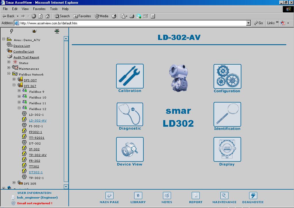
3 LD302 - AssetView HMI LD302 - ASSETVIEW HMI LD302 Home Page This manual describes the pages developed for LD302 maintenance using AssetView. The figure below shows the LD302 initial page and its options: Figure 1. LD302 Home Page The following sub-sections will describe each one of the pages developed for the device maintenance. 3

4 User s Manual LD302 Identification Page This page displays relevant information to the pressure transmitter. The user can easily identify and specify the transmitter in the physical plant. Figure 2. Identification Page Device TAG DEVICE TYPE DEVICE SERIAL NUMBER DEVICE REVISION HARDWARE REVISION DEVICE ID MANUFACTURER MAIN BOARD SERIAL NUMBER FIRMWARE REVISION DD REVISION ORDERING CODE Indicates the tag associated to the transmitter in the physical plant. The tag can have up to 32 characters. Identifies the transmitter type for a specific manufacturer. Indicates the transmitter serial number. Indicates the transmitter revision. Indicates the transmitter hardware revision. Indicates the transmitter identification code. This code can have up to 32 characters. Identifies the transmitter manufacturer. Indicates the serial number of the transmitter main board. Indicates the transmitter firmware revision. Indicates the DD revision. Indicates the transmitter ordering code. Sensor SENSOR TYPE SENSOR FLUID SENSOR RANGE CODE SENSOR ISOLATION MATERIAL SENSOR SERIAL NUMBER Indicates the transmitter sensor type. Indicates the fluid of the transmitter s sensor. Indicates the range code of the transmitter s sensor. Indicates the sensor isolation material. Indicates the transmitter sensor serial number. 4

5 LD302 - AssetView HMI Flange FLANGE TYPE FLANGE MATERIAL DRAIN/VENT MATERIAL O-RING MATERIAL Indicates the flange type. Indicates the flange material. Indicates the drain/vent material. Indicates the o-ring material. Remote Seal NUMBER OF REMOTE SEALS REMOTE SEAL TYPE REMOTE SEAL FLUID REMOTE SEAL ISOLATION MATERIAL Indicates the number of remote seals. Indicates the remote seal type. Indicates the remote seal fluid. Indicates the remote seal isolation material. LD302 Configuration Page There are some parameters in the LD302 transducer block that can be used in the predictive and proactive maintenance. It is possible to detect the performance decreasing by comparing the current parameters with the standard values and then schedule the maintenance. The user can check the general status diagnostic in the LD302 Diagnostic Page (refer to the next section). This status is generated according to the user configuration in the LD302 Configuration Page. For example, the Sensor Failure diagnostic may be caused by an overpressure in the sensor. Figure 3. Configuration Page 5
6 User s Manual Device Operation Mode Indicates the operation mode for the device: OOS AUTO MAN If this mode is selected, the value of the Mode Block parameter will be Out of Service for the Resource, Transducer and Analog Output blocks. If this mode is selected, the value of the Mode Block parameter will be Auto for the Resource, Transducer, Display and Analog Output blocks. If this mode is selected, the value of the Mode Block parameter will be Manual for the Analog Output block, and Auto for the Resource, Transducer and Display blocks. Measured Type Select the type of the measured variable: LEVEL PRESSURE FLOW Indicates the transmitter is measuring level. Indicates the transmitter is measuring pressure. Indicates the transmitter is measuring flow. Measurement Configuration AUTO ZERO CHARACTERIZATION FUNCTION LOW CUT OFF Enables and disables the zero cutoff. Enables and disables the pressure characterization curve. Indicates the function that acts in the Primary Value: Linear or Table. Indicates the value of the pressure cutoff. If the pressure value is lower than the value indicated by Low Cut Off, zero ( 0 ) will be displayed. Engineering Variable UNIT Engineering unit. 0% Value of the pressure corresponding to 0%, in EU. 100% Value of the pressure corresponding to 100%, in EU. Process Variable UNIT LOWER RANGE UPPER RANGE Unit of the process variable. Lower limit of the process variable. Upper limit of the process variable. Alert Configuration MAXIMUM OFFSET DEVIATION OVERPRESSURE LIMIT MAXIMUM GAIN DEVIATION MAXIMUM NUMBER OF OVERPRESSURE Indicates the maximum offset deviation before an alarm is generated. Defines the maximum overpressure limit before an alarm is generated. Defines the maximum gain before an alarm is generated. Defines the maximum number of overpressure before an alarm is generated. 6

7 LD302 - AssetView HMI LD302 Diagnostics Page The user can check the general status diagnostic in the LD302 Diagnostic Page. Figure 4. Diagnostic Page Device Status MAXIMUM PRESSURE MEASURED MAXIMUM TEMPERATURE MEASURED CURRENT OFFSET CURRENT SPAN Indicates the maximum pressure measured. Indicates the maximum temperature measured. Indicates the current calibrated offset. Indicates the current calibrated span. Diagnosis This field shows the continuous diagnostic status for the device, including the function block condition, the mechanical module condition and the sensor condition. POWER UP SENSOR FAILURE MEMORY FAILURE OUT OF SERVICE DEVICE NEEDS MAINTENANCE SOON DEVICE NEEDS MAINTENANCE NOW CALIBRATION ERROR Indicates that the device has executed the initial operation procedure. Indicates a failure in the sensor, such as overpressure. Indicates an electronic failure according to the internal checking procedure, such as an incorrect checksum detected in the main memory. Indicates that the function block is out of service. The internal diagnostic according to the user configuration or device internal checking has detected that the device will need maintenance soon. This diagnostic is related to overpressure in the sensor. The internal diagnostic according to the user configuration or device internal checking has detected that the device needs maintenance. This diagnostic is related to the sensor calibration. Indicates that an error occurred during the device calibration, or a calibration error has been detected while operating the device. 7

8 User s Manual BLOCK CONFIGURATION ERROR DATA INTEGRITY ERROR SOFTWARE ERROR ELECTRONICS FAILURE GENERAL ERROR Indicates that there is an error related to the XD_SCALE parameter in the AI function block. Indicates that data stored in the system may be no longer valid, for example, because the checksum of the data in the RAM memory has failed when compared to the data in the non-volatile memory. The software has detected an error that may have been caused by a deviation of a service routine, an interruption, a lost pointer, etc. An electronic component has failed. A general error related to the device has been detected. LD302 Calibration Page This page displays configuration data used in the calibration procedures. Pressure Calibration Information CALIBRATION UNIT SENSOR LOWER RANGE LIMIT SENSOR UPPER RANGE LIMIT MINIMUM SPAN CURRENT LOW POINT CALIBRATION Figure 5. Calibration Page Indicates the unit for the pressure calibration procedure. Indicates the lower limit for the range s sensor. Indicates the upper limit for the range s sensor. Indicates the minimum value allowed between the lower and upper points of the calibration. Indicates the current lower point of the pressure calibration. 8

9 LD302 - AssetView HMI CURRENT HIGH POINT CALIBRATION FACTORY LOW POINT CALIBRATION FACTORY HIGH POINT CALIBRATION PRESSURE MEASURED TEMPERATURE MEASURED Indicates the current higher point of the pressure calibration. Indicates the factory s lower point of the pressure calibration. Indicates the factory s higher point of the pressure calibration. Indicates the pressure measured by the device. Indicates the temperature measured by the device. Temperature Calibration Information CALIBRATION UNIT CALIBRATION TEMPERATURE Calibration Methods Indicates the unit for the temperature calibration procedure. Indicates the value of the last temperature calibration. NOTE When the transmitter is installed, it is recommended to run the Lower Pressure Calibration procedure to minimize the mounting. Please refer to the transmitter manual for further details. LOWER PRESSURE CALIBRATION: This method is used when calibrating the lower pressure point. The user can select the calibration unit and type the value of the pressure applied as reference value to the transmitter, observing the sensor limits and the minimum span. When this method is selected, a message appears warning the user that this procedure must be executed when the process stops or the plant control is set to manual. Figure 6. Configuring the Mode Block Click Yes, apply the pressure and wait for the sensor stabilization. Figure 7. Stabilizing the Pressure Click OK and the pressure measured will be shown. Figure 8. Confirming the Value of the Pressure 9


10 User s Manual If the value is correct, click Yes to conclude this procedure. Otherwise, click No and type the pressure value: Figure 9. New Pressure Value Click OK to apply the new pressure value, and then click Yes to confirm the alteration, as shown in Figure 8. The calibration procedure will be concluded. UPPER PRESSURE CALIBRATION: This method is similar to the Lower Pressure Calibration procedure described above. It is used when calibrating the pressure with the user s reference instead of the manufacturer s reference. Figure 10. Configuring the Mode Block Click Yes, apply the pressure, and wait for the sensor stabilization. Figure 11. Stabilizing the Pressure Click OK and the pressure measured will be shown. Figure 12. Confirming the Value of the Pressure If the value is correct, click Yes to conclude this procedure. Otherwise, click No, and type the pressure value: Figure 13. New Pressure Value 10

11 LD302 - AssetView HMI Click OK to apply the new pressure value, and then click Yes to confirm the alteration, as shown in Figure 12. The calibration procedure will be concluded. SENSOR CHARACTERIZATION: This method is used to correct the sensor reading in several points. Use an accurate and stable pressure source to guarantee that the accuracy is at least three times better than the transmitter accuracy. Figure 14. Configuring the Mode Block Click Next and wait for the pressure stabilization before performing the trim. The characteristic curve of the sensor can be slightly nonlinear at a certain temperature and for some ranges. This nonlinearity can be corrected by the Characterization Trim. The user can characterize the transmitter with the desired operating range to obtain a better accuracy. The characterization is determined from two up to five points. Apply the pressure to the transmitter and waits the sensor stabilization. Figure 15. Configuring the First Point The pressure measured will be shown. Type the first point value, and click Next Point. Apply pressure to the second point click Next Point, and then, successively up to the last point. Up to five points can be inserted. Click Finish to conclude the procedure. NOTE When more than two and less than five points are used, after insert them, and clicking Next the following figure will appear. In the Curve Y (%) and Curve X (%) tabs only the calibrated points will appear before clicking the Next option. 11


12 User s Manual Figure 16. Finishing the Points Configuration Type the location when the Sensor Characterization procedure is executed, and click Submit. Click Finish to conclude the procedure. TEMPERATURE CALIBRATION This method is used to calibrate the temperature sensor. Figure 17. Stabilizing the Temperature If the value is correct, click Next. Otherwise, type the correct temperature value, click Submit, wait for the sensor stabilization, and then click Next. The following figure will appear. 12


13 LD302 - AssetView HMI Figure 18. New Temperature Value Type the location when the Temperature Calibration procedure is executed, and click Submit. Click Finish to conclude the procedure. LD302 Display Page The user can save the data shown in the device's display. Figure 19. Display Page 13

14 User s Manual Display BLOCK TAG PARAMETER SUB INDEX MNEMONIC INC DEC DECIMAL POINT NUMB ACCESS ALPHA NUM Shows the tags list of the available instantiated blocks. Shows the list of available parameters to be displayed in the LCD for the selected block in the Block Tag option. Indicates the sub-index of the selected parameter. Indicates the mnemonic of the selected parameter in the Parameter option. Indicates the value to be added or subtracted when acting the parameter via local adjustment. Indicates the number of digits after the decimal point that will be shown in the LCD. The user can select the access type of the selected parameter: monitoring or action. Indicates if the alphanumeric field will be used for mnemonic or for value. LD302 Device View Page The user can monitor the device's data opening the Device View page. Figure 20. Device View Page 14
Specifications and information are subject to change without notice. Up-to-date address information is available on our website.
 www.smar.com Specifications and information are subject to change without notice. Up-to-date address information is available on our website. web: www.smar.com/contactus.asp FY302 AssetView IHM FY302 -
Ultima. X Series Gas Monitor
 Ultima X Series Gas Monitor Safety Manual SIL 2 Certified " The Ultima X Series Gas Monitor is qualified as an SIL 2 device under IEC 61508 and must be installed, used, and maintained in accordance with
2600T Series Pressure Transmitter Models 264DC Differential and 264HC Gage Level Transmitters. Kent-Taylor
 INDUSTRIAL INSTRUMENTS AND CONTROLS SPECIALIST Kent-Taylor 2600T Series Pressure Transmitter Models 264DC Differential and 264HC Gage Level Transmitters Features Include Base accuracy : ±0.075% Span limits
HART Communications Board
 - HART Communications Board (Highway Addressable Remote Transducer) User Manual Document No. Sensidyne, LP. 1000 112 th Circle N, Suite 100 St. Petersburg, Florida 33716 USA 800-451-9444 +1 727-530-3602
Data Sheet T 8389 EN. Series 3730 and 3731 Types , , , and. EXPERTplus Valve Diagnostic
 Data Sheet T 8389 EN Series 3730 and 3731 Types 3730-2, 3730-3, 3730-4, 3730-5 and Type 3731-3 Electropneumatic Positioners EXPERTplus Valve Diagnostic Application Positioner firmware to detect potential
Hydro-Control V User Guide
 Hydro-Control V User Guide Hydronix Part no: HD0193 Version 2.3.0 Revision date: July 2006 1 COPYRIGHT Neither the whole or any part of the information contained in nor the product described in this documentation
USER MANUAL. Intelligent Diagnostic Controller IDC24-A IDC24-AF IDC24-AFL IDC24-F IDP24-A * IDP24-AF * IDP24-AFL * IDP24-F * 1/73
 USER MANUAL Intelligent Diagnostic Controller IDC24-A IDC24-AF IDC24-AFL IDC24-F IDP24-A * IDP24-AF * IDP24-AFL * IDP24-F * *) Require software ID: DID-SW-001 1/73 Table of contents 1 General... 3 1.1
How to specify a product. Process Sensors and Mechanical Instruments
 How to specify a product Process Sensors and Mechanical Instruments Keep the overview. Here is some guideline information on how to specify our products. Intended as supplementary help to specification
Using Modbus Protocol with the ALTUS Net Oil Computer. Instruction Manual
 Using Modbus Protocol with the ALTUS Net Oil Computer Instruction Manual November 2000 Using Modbus Protocol with the ALTUS Net Oil Computer Instruction Manual November 2000 For technical assistance,
Device Description User Manual Logix 520MD Positioners
 Device Description User Manual Logix 520MD Positioners GENERAL INFORMATION... 3 INTRODUCTION... 3 QUALIFIED PERSONNEL... 3 USING THIS DOCUMENT... 3 TERMS CONCERNING SAFETY... 3 1 STATUS... 4 1.1 CMD SOURCE...
2600T Series Pressure Transmitters Plugged Impulse Line Detection Diagnostic. Pressure Measurement Engineered solutions for all applications
 Application Description AG/266PILD-EN Rev. C 2600T Series Pressure Transmitters Plugged Impulse Line Detection Diagnostic Pressure Measurement Engineered solutions for all applications Increase plant productivity
The M-Series Eletta Flow Meter High accuracy DP Flow Meter with multiple functions
 The M-Series Eletta Flow Meter High accuracy DP Flow Meter with multiple functions Flow Meter with multiple functions for gases and liquids M3 The M-series Flow Meter, with its versatile and user-friendly
Differential Pressure Transmiter
 Differential Pressure Transmiter Description The is an economical alternative to established differential pressure transmitters. It combines state of the art electronics and a high performance sensor;
Installation and Operation Manual
 Manual Static pressure transducer with controller Differential static pressure transducer with analog output and optional PI control mode Large diaphragm element with differential transformer Transducer
955730_1 4/17/18. FlowSense Operator s Guide For Gen2 20/20 SeedSense Displays
 955730_1 4/17/18 FlowSense Operator s Guide For Gen2 20/20 SeedSense Displays Contents System Setup and Operation...3 Configuring Monitor for FlowSense...3 FlowSense Setup...4 Liquid Alerts...8 Monitoring
Series 3730 and Series 3731 EXPERTplus Valve Diagnostics with Partial Stroke Test (PST)
") Series 3730 and Series 3731 EXPERTplus Valve Diagnostics with Partial Stroke Test (PST) Application Positioner firmware for early detection of control valve faults giving maintenance recommendations. Valid
Series 3730 and Series 3731 EXPERTplus Valve Diagnostics with Partial Stroke Test (PST) Application Positioner firmware for early detection of control valve faults giving maintenance recommendations. Valid
BIOGAS COMBUSTION PLANT MAINTENANCE MANUAL
 BIOGAS COMBUSTION PLANT MAINTENANCE MANUAL (PLANT MAINTENANCE MANUAL) Puente Gallego Landfill, Rosario (Argentina) ARIA.BIZ S.A. Montevideo 589, 7 floor 1019 Capital federal Argentina Tel: +54 11 5171
DTG - LCD Digital Temperature Gauge USER MANUAL
 DTG - LCD USER MANUAL Page 1 of 7 USERS GUIDE page 1. Description 3 2. Function 3 3. Safety Instruction 3 3.1. Safety Conventions 3 3.2. Proper Use 3 4. Installation 4 4.1. Unpacking 4 4.2. Storage 4 4.3.
Fisher FIELDVUE DVC6200f Digital Valve Controller PST Calibration and Testing using ValveLink Software
 Instruction Manual Supplement DVC6200f Digital Valve Controller Fisher FIELDVUE DVC6200f Digital Valve Controller PST Calibration and Testing using ValveLink Software The test procedure contained in this
Safety Manual VEGAVIB series 60
 Safety Manual VEGAVIB series 60 NAMUR Document ID: 32005 Contents Contents 1 Functional safety... 3 1.1 General information... 3 1.2 Planning... 4 1.3 Adjustment instructions... 6 1.4 Setup... 6 1.5 Reaction
Description of Device Parameters Proline Prowirl 200 HART. Vortex flowmeter. Products Solutions Services. Main menu Language.
 GP01019D/06/EN/02.15 71308256 Valid as of version 01.02.zz (Device firmware) Products Solutions Services of Device Parameters Proline Prowirl 200 HART Vortex flowmeter XXXXXXXXX 20.50 Main menu 0104-1
IDL01. Battery Powered Precision Digital Gauge for Leak Testing. Stainless Steel Sensor. class 0.05
 IDL0 Battery Powered Precision Digital Gauge for Leak Testing Stainless Steel Sensor class 0.05 Nominal pressure from 0 00 mbar up to 0... 00 bar Special characteristics modular sensor concept data logger
BAPI Pressure Line of Products - FAQs
 Table of Contents 1. Several manufacturers produce pressure transmitters, why should I purchase from BAPI?... p. 2 2. BAPI makes several styles of pressure transmitters. What are the features of each?...
These Terms and conditions apply to audit trails incorporated in weighing and measuring devices and systems 1.
 Title: Terms and Conditions for the Approval of Metrological Audit Trails Effective Date: 2006-03-16 Page: 1 of 9 Revision: 1.0 Application These Terms and conditions apply to audit trails incorporated
Datasheet: K-30 ASCII Sensor
 Datasheet: K-30 ASCII Sensor The K30 ASCII sensor is a low cost, infrared and maintenance free transmitter module intended to be built into different host devices that require CO2 monitoring data. The
Instructions for SMV 3000 Multivariable Configuration (MC) Data Sheets
 Data Sheets") Instructions for SMV 3000 Multivariable Configuration (MC) Data Sheets Similar to the TC option for ST 3000 transmitters, the MC option for the SMV 3000 provides a service to our customers which results
Instructions for SMV 3000 Multivariable Configuration (MC) Data Sheets Similar to the TC option for ST 3000 transmitters, the MC option for the SMV 3000 provides a service to our customers which results
Model EXAxt AV550G. Averaging Oxygen Analyzer
 Model EXAxt AV550G Averaging Oxygen Analyzer Oxygen Measurement and Flyash Oxygen % vs cell EMF The O2 mation, model AV550, averaging oxygen analyzer was designed with a focus Calibration 1 on practical
Safety Manual VEGAVIB series 60
 Safety Manual VEGAVIB series 60 Contactless electronic switch Document ID: 32002 Contents Contents 1 Functional safety... 3 1.1 General information... 3 1.2 Planning... 4 1.3 Adjustment instructions...
Flow and Energy Measurement F-5400 THERMAL MASS FLOW METER
 THERMAL MASS FLOW METER s Series Thermal Mass Flow Meters provide accurate and reliable flow measurement for natural gas, compressed air, and other industrial gas applications. Natural Gas Compressed Air
Pneumatic high-pressure controller Model CPC7000
 Calibration technology Pneumatic high-pressure controller Model CPC7000 WIKA data sheet CT 27.63 Applications Automotive and avionics industry Industry (laboratory, workshop and production) Transmitter
GasSense NDIR User Manual
 INDEX INDEX... 1 1. OVERVIEW... 2 2. TECHNICAL DATA... 3 3. SPECIFICATIONS... 4 4. PRODUCT DESCRIPTION... 5 4.1 Mechanical details... 5 4.2 Piping... 7 4.3 Connections... 7 5. INSTALLATION... 10 6. CALIBRATION
RAM Operation Manual
 RAM 4021-1 Operation Manual Worldwide Manufacturer of Gas Detection Solutions TABLE OF CONTENTS RAM 4021-1 For Your Safety... 2 Description... 2 Setup Mode... 3 Lights/Alarms... 3 Operation... 4 Calibration...
AMS 6916 Board mount pressure sensor with ratiometric analog output
 FEATURES Piezoresistive pressure sensor with amplified analog output Calibrated and temperature compensated Ratiometric voltage output, 0.5 4.5 V Digital signal conditioning, 12 bit output resolution Differential,
Special Documentation Proline Promass 80, 83
 SD00077D/06/EN/14.14 71272498 Products Solutions Services Special Documentation Proline Promass 80, 83 Functional safety manual Coriolis mass flow measuring system with 4 20 ma output signal Application
The benefits of the extended diagnostics feature. Compact, well-proven, and flexible
 ABB MEASUREMENT & ANALYTICS TECHNICAL INFORMATION PositionMaster EDP300 Extended Diagnostics Compact, well-proven, and flexible The benefits of the extended diagnostics feature The PositionMaster EDP300
COMPRESSOR PACK SUCTION CONTROLLER TYPE: LP41x
 Electrical Installation Requirements Care should be taken to separate the power and signal cables to prevent electrical interference and possible damage due to inadvertent connection. SUPPLY E L N LN2
ACV-10 Automatic Control Valve
 ACV-10 Automatic Control Valve Installation, Operation & Maintenance General: The Archer Instruments ACV-10 is a precision automatic feed rate control valve for use in vacuum systems feeding Chlorine,
Vehicle- or rack-mounted liquefied gas meters, pump supplied
 Purpose This inspection procedure outline (IPO) defines the minimum tests which must be performed to ensure that basic volumetric measuring devices comply with the legislation. Application Rack/fixed metering
AMT-Ex Dewpoint Transmitter
 AMT-Ex Dewpoint Transmitter Instruction Manual Alpha Moisture Systems Alpha House 96 City Road Bradford BD8 8ES England Tel: +44 1274 733100 Fax: +44 1274 733200 email: mail@amsytems.co.uk web: www.amsystems.co.uk
RAM Operation Manual. Worldwide Manufacturer of Gas Detection Solutions
 RAM 4021 Operation Manual Worldwide Manufacturer of Gas Detection Solutions TABLE OF CONTENTS RAM 4021 For Your Safety... 2 Description.... 2 Setup Mode.... 2 Lights/Alarms.... 3 Operation.... 4 Calibration....
Intelligent SUNTEX DC-5310(RS) Dissolved Oxygen Transmitter
 Dissolved Oxygen Transmitter") Intelligent SUNTEX DC-5310(RS) Dissolved Oxygen Transmitter Overview C % ppm 4~20mA Analog Output ppb Power Supply 100~240 VAC mg/l Dimensions 96 x 96 x 132mm RS-485 Digital Output (for DC-5310-RS only)
Intelligent SUNTEX DC-5310(RS) Dissolved Oxygen Transmitter Overview C % ppm 4~20mA Analog Output ppb Power Supply 100~240 VAC mg/l Dimensions 96 x 96 x 132mm RS-485 Digital Output (for DC-5310-RS only)
SIL Safety Manual. ULTRAMAT 6 Gas Analyzer for the Determination of IR-Absorbing Gases. Supplement to instruction manual ULTRAMAT 6 and OXYMAT 6
 ULTRAMAT 6 Gas Analyzer for the Determination of IR-Absorbing Gases SIL Safety Manual Supplement to instruction manual ULTRAMAT 6 and OXYMAT 6 ULTRAMAT 6F 7MB2111, 7MB2117, 7MB2112, 7MB2118 ULTRAMAT 6E
Continuous Gas Analysis In situ laser gas analyzers TÜV and MCERTS add-on for LDS 6 operating instructions Compact Operating Instructions
 Continuous Gas Analysis In situ laser gas analyzers Compact Operating Instructions 1 LDS 6 TÜV/MCERTS certified analyzers for NH3/H2O, NH3 and H2O 1.1 Operation requirements Please observe the following:
For Multi-Parameter Meters see mvx
 Design Features VORTEX IN-LINE FLOW METERS For Multi-Parameter Meters see m Principles of Operation n No moving parts to wear or fail. n Electronics can be remotely mounted up to 30.5 m (0 ft). n No fluid
BUBBLER CONTROL SYSTEM
 BUBBLER CONTROL SYSTEM Description: The HDBCS is a fully automatic bubbler system, which does liquid level measurements in water and wastewater applications. It is a dual air compressor system with, air
COMPARISON OF DIFFERENTIAL PRESSURE SENSING TECHNOLOGIES IN HOSPITAL ISOLATION ROOMS AND OTHER CRITICAL ENVIRONMENT APPLICATIONS
 COMPARISON OF DIFFERENTIAL PRESSURE SENSING TECHNOLOGIES IN HOSPITAL ISOLATION ROOMS AND OTHER CRITICAL ENVIRONMENT APPLICATIONS APPLICATION NOTE LC-136 Introduction Specialized spaces often times must
Vehicle-mounted meters, pump supplied
 Purpose This inspection procedure outline (IPO) defines the minimum tests which must be performed to ensure that basic volumetric measuring devices comply with the legislation. Application Vehicle-mounted
RAM 4021-PR. Operation Manual. Worldwide Manufacturer of Gas Detection Solutions
 RAM 4021-PR Operation Manual Worldwide Manufacturer of Gas Detection Solutions TABLE OF CONTENTS RAM 4021-PR For Your Safety... 2 Description.... 2 Setup Mode.... 2 Lights/Alarms.... 3 Operation.... 4
Scoreboard Operator s Instructions MPC Control
 Scoreboard Operator s Instructions MPC Control Some features on the keyboard overlay may not be included on the particular model being operated. Since 1934 Retain this manual in your permanent files 1/21/2011
RAM Operation Manual. Worldwide Manufacturer of Gas Detection Solutions
 RAM 4021 Operation Manual Worldwide Manufacturer of Gas Detection Solutions TABLE OF CONTENTS RAM 4021 For Your Safety... 2 Description.... 2 Setup Mode.... 2 Lights/Alarms.... 3 Operation.... 4 Calibration....
For Multi-Parameter Meters see mvx
 VORTEX IN-LINE FLOW METERS Design Features For Multi-Parameter Meters see mvx Principles of Operation VX No moving parts to wear or fail. Electronics can be remotely mounted up to 30.5 m (0 ft). No fluid
Design Envelope Booster. Sequence of operation
 Design Envelope Booster Sequence of operation File No: 62.835 Date: february 11, 2015 Supersedes: 62.835 Date: july 11, 2014 sequence of operation Design Envelope Booster 2 general The packaged domestic
Instruction Manual. BZ7002 Calibration Software BE
 Instruction Manual BZ7002 Calibration Software BE6034-12 Index _ Index Index... 2 Chapter 1 BZ7002 Calibration Software... 4 1. Introduction... 5 Chapter 2 Installation of the BZ7002... 6 2. Installation
For a similar sensor with o-ring mounting, refer to the 85BSD digital output pressure sensor.
 Weldable or threaded process fittings Pressure/temperature read-out Digital output ASIC calibrated Absolute, gage Cable/connector option Low power option DESCRIPTION The 85BSD is a small profile, media
Pegas 4000 MF Gas Mixer InstructionManual Columbus Instruments
 Pegas 4000 MF Gas Mixer InstructionManual Contents I Table of Contents Foreword Part I Introduction 1 2 1 System overview... 2 2 Specifications... 3 Part II Installation 4 1 Rear panel connections...
RAM 4021-DPX Operation Manual
 RAM 4021-DPX Operation Manual Worldwide Manufacturer of Gas Detection Solutions TABLE OF CONTENTS ABL 4021-DPX / RAM 4021-DPX For Your Safety... 3 Description... 3 Setup Mode... 4 Lights/Alarms... 4 Operation...
Electronic gas volume corrector model DGVC-04
 Electronic gas volume corrector model DGVC-04 1. Introduction The following user s manual gives information about the installation, configuration, usage and storage of the electronic gas volume corrector
PTG100 Precision Test Gauge
 PTG100 Precision Test Gauge User Manual PD1007 Rev B 03/28/2014 Palmer Instruments Inc. 234 Old Weaverville Road Asheville, NC 28804 Toll Free: 800-421-2853 Phone: 828-658-3131 Fax: 828-658-0728 Email:
86BSD Backside Digital Output
 Stainless steel with O-ring seal Pressure/temperature read-out Backside digital output ASIC calibrated Absolute, gage Cable/connector option Low power option DESCRIPTION The 86BSD is a small profile, media
Features. Description
 Features Fast response flow meter ideal for inert gas and liquid mass flow measurement applications Smart electronics permit field adjustment of critical flow meter settings Field validation of flow meter
Neles ValvGuard VG9000H Rev 2.0. Safety Manual
 Neles ValvGuard VG9000H Rev 2.0 Safety Manual 10SM VG9000H en 11/2016 2 Neles ValvGuard VG9000H Rev 2.0 Safety Manual Table of Contents 1 General information...3 1.1 Purpose of the document... 3 1.2 Description
YT-3300 / 3301 / 3302 / 3303 / 3350 / 3400 /
 Smart positioner YT-3300 / 3301 / 3302 / 3303 / 3350 / 3400 / 3410 / 3450 Series SIL Safety Instruction. Supplement to product manual July. 2015 YTC Ver 1.06 1 Table of contents 1 Introduction... 3 1.1
Portable Gas Monitor GX User Maintenance Manual (H4-0050)
") H4E-0050 Portable Gas Monitor GX-8000 User Maintenance Manual (H4-0050) Need of Maintenance and Servicing This gas monitor must be maintained in a normal state at all times to prevent accidents due to
H4E-0050 Portable Gas Monitor GX-8000 User Maintenance Manual (H4-0050) Need of Maintenance and Servicing This gas monitor must be maintained in a normal state at all times to prevent accidents due to
BUYER S GUIDE AQUAlogger 530WTD
 OCEAN & ENVIRONMENTAL BUYER S GUIDE AQUAlogger 530WTD Wireless Temperature and Depth Logger AQUAlogger 530WTD The AQUAlogger 530WTD has an innovative design that includes the ability to transfer stored
G200 Analyzer Range. Operating Manual
 G200 Analyzer Range Operating Manual G200 N 2 0 0-1,000ppm G210 N 2 0 0-100% VIASENSOR 850 South Via Lata Suite 112 Colton, CA 92324 USA Toll Free: 855 VIASENSOR Tel: +1 (909) 783-9472 Fax: +1 (909) 825-0591
Race Screen: Figure 2: Race Screen. Figure 3: Race Screen with Top Bulb Lock
 Eliminator Competition Stand Alone Mode - Instruction Manual Main Menu: After startup, the Eliminator Competition will enter the Main Menu. Press the right/left arrow buttons to move through the menu.
Location of CC Number if not located with the identification:
 This checklist is used for Technical Policy U. Evaluating electronic digital indicators submitted separate from a measuring element. This section is intended for lab testing only. Is permanence necessary?
WHITEPAPER. Integrated process monitoring of dosing pressures
 Integrated process monitoring of dosing pressures Detect and avoid errors during dosing with the flowplus 16 dosing pressure monitoring system and flowscreen Fig. 1: flowplus 16 relative pressure sensor
sitrans p Instruction Manual Edition 10/2003
 Instruction Manual Edition 10/2003 sitrans p Transmitters for pressure, differential pressure and flow, level, absolute pressure from pressure series 7MF4*33-... s 7MF4*33-... Edition 10/2003 Instruction
Doc. no.dit om005 PRODUCT NAME. IO-Link/ELECTRO-PNEUMATIC REGULATOR. MODEL / Series / Product Number ITV*0*0-IO****-X395
 Doc. no.dit-69900-om005 PRODUCT NAME IO-Link/ELECTRO-PNEUMATIC REGULATOR MODEL / Series / Product Number ITV*0*0-IO****-X395 This is the operation manual for the IO-Link compliant ITV. For other contents
Pneumatic high-pressure controller Model CPC7000
 Calibration technology Pneumatic high-pressure controller Model CPC7000 WIKA data sheet CT 27.63 Applications Healthcare and avionics industry Industry (laboratory, workshop and production) Transmitter
combustion efficiency monitoring General Purpose Applications Flue gas oxygen analyzers Combustion & Environmental Monitoring An Company
 combustion efficiency monitoring Flue gas oxygen analyzers General Purpose Applications Combustion & Environmental Monitoring An Company Flue Gas Oxygen Genesis is a range of flue gas analyzers for measuring
REASONS FOR THE DEVELOPMENT
 7 Series 7 Series +24VDC VDC OUTPUT MICROPROCESS. E P IN EXH OUT 7 Series 7 ø,8 8 7 Series 9 5 8 9 7 Series Display features The proportional regulator has a 3 /2 digit display and a three-pushbutton
ACCURATE PRESSURE MEASUREMENT FOR STEAM TURBINE PERFORMANCE TESTING
 ACCURATE PRESSURE MEASUREMENT FOR STEAM TURBINE PERFORMANCE TESTING Blair Chalpin Charles A. Matthews Mechanical Design Engineer Product Support Manager Scanivalve Corp Scanivalve Corp Liberty Lake, WA
Life Cycle Benefits: Maintenace (Control Valve Diagnostic and Field Device Diagnostic Management)
") Life Cycle Benefits: Maintenace (Control Valve Diagnostic and Field Device Diagnostic Management) Yasushi Kudo Yamatake Corporation Aaron Chen Azbil Taiwan Contents I. Prologue II. Possibilities of CV
Life Cycle Benefits: Maintenace (Control Valve Diagnostic and Field Device Diagnostic Management) Yasushi Kudo Yamatake Corporation Aaron Chen Azbil Taiwan Contents I. Prologue II. Possibilities of CV
Copyright 2004 by the Thomas G. Faria Corporation, Uncasville CT No part of this publication may by reproduced in any form, in an electronic
 Copyright 2004 by the Thomas G. Faria Corporation, Uncasville CT No part of this publication may by reproduced in any form, in an electronic retrieval system or otherwise, without the prior written permission
Instruction Manual Dräger MSI P7 and MSI P7 plus
 Dräger MSI GmbH Rohrstraße 32 58093 Hagen Tel.: +49-2331 / 9584-0 Fax: +49-2331 / 9584-29 e-mail: info@draeger-msi.de D 923; Edition 2011-01-01 Content 1. General Hints Page 4 2. The Instrument 2.1 Front
A4s Operation Manual
 A4s Operation Manual Safety Instruction Please read this manual carefully, also with related manual for the machinery before use the controller. For installing and operating the controller properly and
SDI mA Pressure Transducer (Submersible + Dry) Model WL2100 Operating Manual
 Model WL2100 Operating Manual") SDI-12 + 4-20mA Pressure Transducer (Submersible + Dry) Model WL2100 Operating Manual (Submersible) WL2100W (Dry) WL2100D QUALITY SYSTEM ISO: 9001 CERTIFIED HYQUEST SOLUTIONS PTY LTD 48-50 Scrivener St,
SDI-12 + 4-20mA Pressure Transducer (Submersible + Dry) Model WL2100 Operating Manual (Submersible) WL2100W (Dry) WL2100D QUALITY SYSTEM ISO: 9001 CERTIFIED HYQUEST SOLUTIONS PTY LTD 48-50 Scrivener St,
PRODUCT CONFORMITY CERTIFICATE
 PRODUCT CONFORMITY CERTIFICATE This is to certify that the Endura AZ20 / AZ30 measuring system Manufactured by: ABB Ltd Oldends Lane Stonehouse Gloucestershire GL10 3TA has been assessed by Sira Certification
PX3005. Rangeable Industrial Pressure Transmitter M-5721/1018
 PX3005 Rangeable Industrial Pressure Transmitter INTRUCTION HEET -5721/1018 hop online at omega.com e-mail: info@omega.com For latest product manuals: omegamanual.info ! Pressure / differential pressure
Basic Nitriding Sampling System Hydrogen Analyzer with Calculated % DA, % NH 3, and K N Values. Operations Manual
 Basic Nitriding Sampling System Hydrogen Analyzer with Calculated % DA, % NH 3, and K N Values Operations Manual Please read, understand, and follow these instructions before operating this equipment.
Operating Manual. SUPREMA Calibration. Software for Fire and Gas Warning Units. Order No.: /01. MSAsafety.com
 Operating Manual Software for Fire and Gas Warning Units Order No.: 10154656/01 MSAsafety.com MSA Europe GmbH Schlüsselstrasse 12 8645 Rapperswil-Jona Switzerland info.ch@msasafety.com www.msasafety.com
4000 series (includes 4100, 4200 & 4900)
") 4000 series (includes 4100, 4200 & 4900) Please record your analyser details below Part Number Serial Number Tag Number This page intentionally blank A 1 2 3 4 5 6 B 1 2 3 4 5 No. Value Unit Name I1 12.6
4000 series (includes 4100, 4200 & 4900) Please record your analyser details below Part Number Serial Number Tag Number This page intentionally blank A 1 2 3 4 5 6 B 1 2 3 4 5 No. Value Unit Name I1 12.6
G200 RANGE G200 AND G210 OPERATING MANUAL
 G200 RANGE G200 AND G210 OPERATING MANUAL Page 2 of 61 Table of Contents Manual Guidelines... 5 Safety Related Information... 5 Hyperlinks... 5 Notes... 5 Introduction... 6 The G200 Analyser... 6 The G210
DM01. Please visit our website: Battery Powered Precision Digital Gauge. Stainless Steel Sensor. class 0.05
 DM0 Battery Powered Stainless Steel Sensor class 0.05 Nominal pressure from 0 00 mbar up to 0... 00 bar Special characteristics modular sensor concept data logger graphic display stainless steel housing
eflo ELECTRONIC GAS FLOW METER OPERATIONS MANUAL
 eflo ELECTRONIC GAS FLOW METER OPERATIONS MANUAL Super Systems Inc. 7205 Edington Drive Cincinnati, OH 45249 513-772-0060 Fax: 513-772-9466 www.supersystems.com Super Systems Inc. USA Office Corporate
ETd 04. Battery Powered Precision Digital Gauge. Stainless Steel Sensor. Type: ETd 04. class 0.05
 Battery Powered Stainless Steel Sensor class 0.05 Nominal pressure from 0 100 mbar up to 0... 400 bar Special characteristics modular sensor concept data logger graphic display stainless steel housing
BUBBLER CONTROL SYSTEM
 BUBBLER CONTROL SYSTEM Description: The LDBCS is a fully automatic bubbler system, which does liquid level measurements in water and wastewater applications. It is a dual air compressor system with, air
The HumiSys. RH Generator. Operation. Applications. Designed, built, and supported by InstruQuest Inc.
 The HumiSys RH Generator Designed, built, and supported by InstruQuest Inc. Versatile Relative Humidity Generation and Multi-Sensor System The new HumiSys with single or dual RH probes capabilities is
BAROMETER PRESSURE STANDARD PRESSURE CONTROLLER
 BAROMETER PRESSURE STANDARD PRESSURE CONTROLLER Features ±0.01% FS Measurement & Control Accuracy ±0.001% /ºC Thermal Stability Pressure Ranges from ±1 psid to 1200 psia Applications Barometric Measurement
Operating Instructions EB EN. Series 373x Electropneumatic Positioner Type 373x-5 EXPERT + with FOUNDATION fieldbus communication
 Series 373x Electropneumatic Positioner Type 373x-5 EXPERT + with FOUNDATION fieldbus communication Fig. 1 Valve diagnostics with TROVIS-VIEW Operator Interface Operating Instructions EB 8388-5 EN Firmware
Bante821 Portable Dissolved Oxygen Meter Instruction Manual
 Bante821 Portable Dissolved Oxygen Meter Instruction Manual BANTE INSTRUMENTS CO., LTD Bante821 Portable Dissolved Oxygen Meter 1 Introduction Thank you for selecting the Bante821 portable dissolved oxygen
HEATEC TEC-NOTE Publication No Revised
 HEATEC TEC-NOTE Revised 6-17-10 Setting up Vega radar sensors for Heatec vertical asphalt tanks This document provides information for setting up Vega radar sensors installed on Heatec tanks that store
Additel761 Series Firmware Updates
 Additel761 Series Firmware Updates 2018-09-03 APC V01.XX Vertions before APC V01.03(Included) APC V01.04 APC V01.05 APC V01.06 APC V01.07 APC V01.08 APC V01.09 APC V01.10 APC V01.11 APC V01.12 APC V01.13
Transmitter CS 21 Operation Manual
 Transmitter CS 21 Operation Manual 1194 Oak Valley Drive, Suite 20, Ann Arbor, MI 48108 800-959-0573 734-769-1888 Content Page For your Safety 3 General Description 3 Detection Principle 4 Operation 4
CDS-2000 CO 2 Sensor Verification, Calibration, and Troubleshooting Bulletin
 Electronic Control Manual 216 Sensors and Stats Section S Technical Bulletin CDS-2000 Issue Date 0393 CDS-2000 CO 2 Sensor Verification, Calibration, and Troubleshooting Bulletin Introduction 3 Pre-Verification
Programmable Submersible Level Transmitters
 Programmable Submersible Level Transmitters PTM/N/RS485 CUSTOMER BENEFITS High flexibility due to scalalbe pressure range Digital (RS485) and analogue (4-20mA) output signal in one sensor Available as
AHE58/59 AC Servo System
 AHE58/59 AC Servo System HMI-12 User Manual Safely INstruction Please read this manual carefully, also with related manual for the machine head before use. For perfect operation and safety, installing
780S Ultra High Purity Series
 Smart Ultra High Purity Thermal Gas Mass Flow Meter Features Measures mass flow directly, no seperate temperature or pressure inputs required Field adjustment of critical flow meter settings via on-board