Installation, Maintenance and Operation Manual Pressure Regulator Valve Model DOMUS
|
|
|
- Gerald Bruce
- 5 years ago
- Views:
Transcription


1 Installation, Maintenance and Operation Manual Pressure Regulator Valve Model DOMUS
2 INDEX GENERAL ADVERTSIMENT INSTRUCTIONS PRIOR COMMISSIONING HEALTH AND SAFETY NOISE INSTALLATION OPERATION MAINTENANCE INTRODUCTION MANUAL SCOPE DESCRIPTION SPECIFICATIONS AVAILABLE CONFIGURATIONS AVAILABLE CONNECTIONS TEMPERATURE LIMITS FLOW COEFFICIENT MAXIMUM WORKING PRESSURE ESTIMATE WEIGHTS (kg) SET POINT RANGE SET POINT PRE-REGULADOR ACCURACY AND LOCK UP WORKING PRINCIPLE REGULATOR PILOT (G30F & G32F) PILOT (CORINOX) IN BUILT RELIEF VALVE INSTALLATION FILTER CLEANING FLOW DIRECTION AND SYSTEM INTEGRITY SENSING LINE RECOMMENDED INSTALLATION SCHEME UNIQUE REGULATOR COMMISSIONING AND START-UP GENERAL RECOMMENDATIONS COMMISSIONING ADJUSTMENT OF RESERVE (BY-PASS) LINE LIST OF RECOMMENDED TOOLS TROUBLE SHOOTING MAINTENANCE DRAWINGS / PARTS LIST MAIN VALVE DIAMETER MAIN VALVE DIAMETER PILOT G30F PILOT G32F CORINOX / CORINOX BP
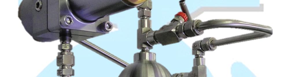
3 1.0 - GENERAL ADVERTSIMENT 1.1 INSTRUCTIONS PRIOR COMMISSIONING It should be clearly understood that with these information hereby presented in the instructions for commissioning that follows, there is no intention to revenue or replace the instructions determined by any other organ or institute and should be done reference to the relevant Standards and/or recommendations existents over this subject. Before any commissioning, it is understood that the execution of proper purification and cleanness procedures that shall be observed and all instructions about pressurization and standard of safety and health, should be strictly observed. The valve suppliers recommendation, as for example, open slowly and open very slowly should be strictly observed. 1.2 HEALTH AND SAFETY Regulators, valves and other pressurized components that contain toxic, flammable gases, or other dangerous products, are potentially dangerous if not operated and kept correctly. It is imperative that all users of such equipment had been adequately educated and oriented for the potential hazards and certified that the responsible personnel for the installation, test, commissioning, operation and maintenance of factory are competent to do this job. The instruction manuals are provide for orientation of users, but presume that they have a basic knowledge level. In case of any doubt or ambiguity that affect the correct procedure, GASCAT must be contacted in order to inform or offer the service and instruction. DO NOT TAKE THE RISK. The phone numbers and for contact are described below: Gascat Indústria e Comércio Ltda. Rodovia SP 73, 1141 Indaiatuba / São Paulo. CEP Phone: Fax: sales@gascat.com.br The following commentaries, while not exaustive, provide orientation of possible hazard sources against the heath and safety NOISE Regulators, valves and other pressure regulators can generate high noise level, which can be prejudicial for people exposed for long period. The users should assure that adequate precautions was take in order to foresee security for the health of employees, according to the standards and recommendations INSTALLATION All the equipment, pipe and vessels are designed to support mechanical efforts as, for example, torch and bending moment, in addition to the internal pressure. However, all care shall be taken during the installation to avoid excess of charge that can cause damage when the system in operation. Excessive tensions can also be caused due of not support the pipe length that can be adequate supported by base frame. All the pressure regulators, slam shut valves, relief valves etc, shall be installed with correct flow direction. Sensing lines are important components of all control systems and it is essential that are correctly installed without insulating valves. Sensing line shall be adequate support to reduce excessive vibration that can cause its rupture. It shall be positioned in order to avoid be used as foot or hand support. It shall be lightly inclined to allow liquid and condensate flow to the main pipe. When necessary (in underground or buried installation) it shall be installed venting pipe with Ø ¼ NPT, positioned in the housing (spring or diaphragm) which shall be extended and positioned in a safety and ventilated place, with protected vent to avoid water and incepts block the way. Auxiliary systems shall not be changed or modified without knowledge of process service conditions and permission of responsible staff OPERATION Depending on regulator type, the valve can be positioned totally open. Consequently, when in operation, the slam shut valve shall be opened slowly in order to the regulator assume its regulating position. If the valves are opened quickly, the upstream pressure can pass to downstream through the pressure regulator over pressurizing the main downstream pipe. All the regulators shall operate with regulating spring specified by manufacture. It is specially important when operating relief and slam shut valve, since non correct spring can avoid the relief to open and slam shut to close. It shall take precautions to avoid water in the venting ways MAINTENANCE Regulators and valves contain gases with pressure sometimes over than the atmospheric pressure. Before trying to investigate the problem or execute the maintenance service in the equipment it shall be safely depressurized. Beyond this, as the gases can be flammable, toxic, corrosive, it means, dangerous, it can be necessary to purge the installation using inert gas. Special precautions are necessary for operation with gases as oxygen or hydrochloric gas and the user shall be protected and the safety procedures implemented. 3
4 Eventually it is not enough to isolate the device of high pressure, since the high pressure can be retained in the isolating valves. Do not try to remove cover, plugs and similar, before device properly released. It is still prudent to consider that the gas in high pressure can be present during cover and plug removal. Practically, all regulators use spiral springs. It is important to reduce the charge of spring. In some case it can contain some charge due of spring housing of device. 2.0 INTRODUCTION 2.1 MANUAL SCOPE This manual has the objective to provide information of operation, installation and maintenance about the pressure regulator model DOMUS manufactured by GASCAT. 2.2 DESCRIPTION The pilot operated pressure regulator model DOMUS was designed by Gascat Engineering, in order to assist application where the pressure regulators shall resist to high pressure and provide high flow, as for example, the Decompression Stations of NG, and can operated in different process service conditions. It has large utilization in gas distribution. Main characteristic is the operating simplicity and easy handling, quick maintenance and relation cost-benefit. 2.3 SPECIFICATIONS AVAILABLE CONFIGURATIONS Active / Monitor System Working / Monitor System Simple Regulating AVAILABLE CONNECTIONS ND 1 x 1 1 x 2 1 x 3 2 x 2 2 x 3 2 x 4 CONNECTIONS Flanges 300#, 600#, 900#, 1500# or 2500# RTJ or RF Flanges 300#, 600#, 900#, 1500# or 2500# RTJ or RF Flanges 300#, 600#, 900#, 1500# or 2500# RTJ or RF Flanges 300#, 600#, 900#, 1500# or 2500# RTJ or RF Flanges 300#, 600#, 900#, 1500# or 2500# RTJ or RF Flanges 300#, 600#, 900#, 1500# or 2500# RTJ or RF Note: For other diameters / connections, consult Gascat Sales Department TEMPERATURE LIMITS Operating Temperature: -22 F to 176 F (-30 C to 80 C). Environment temperature: -22 F to 176 F (-30 C to 80 C). The temperature limits hereby informed or in any applicable standard shall not exceed under any hypotheses, under risk of equipment damage, installation security or of people involved FLOW COEFFICIENT DN 1 x 1 1 x 2 1 x 3 2 x 2 2 x 3 2 x 4 KG ) When sizing for active / monitor system shall consider restriction of 25% in KG of both valves MAXIMUM WORKING PRESSURE MAXIMUM WORKING PRESSURE 250 bar * Working pressure limited by flange class rating according to standard ASME B16.5 The pressure limits hereby informed or in any applicable standard shall not exceed under any hypotheses, under risk of equipment damage, installation security or of people involved ESTIMATE WEIGHTS (kg) DN 600# 900# 1500# 1 x x x
5 2 x x x SET POINT RANGE The pressure regulator model DOMUS can utilize until four different model of pilots to control the pressure depending on the operating conditions: G30F, G32F, Corinox BP and Corinox. PILOT G-30F SPRING COLOR P/N RANGE Grey Green Red Brown Black PILOT G-32F psi ( bar) psi ( bar) psi ( bar) psi ( bar) psi (14 32 bar) SPRING COLOR P/N RANGE Brown Black PILOT CORINOX BP psi (14,0 36,0 bar) psig (28 63 bar) SPRING COLOR P/N RANGE Green Yellow psi (5 11 bar) psi (5,0 20 bar) bar), simultaneously, its utilize pre-regulator model CORINOX. PRE-REGULATOR CORINOX SPRING COLOR P/N RANGE Green ACCURACY AND LOCK UP Accuracy Class - AC up to 2.5; Lock Up - SG up to WORKING PRINCIPLE 3.1 REGULATOR psi (18 80 bar) The pressure regulator Domus works by principle of drop of outlet pressure that acts in the diaphragm lower chamber of main valve. In the absence of flow the regulator remain closed, because the pressure under the diaphragm (outlet pressure) is the same of over the diaphragm, prevailing in the equilibrium of forces only the obturator spring that moves it upward closing the valve. The pilot, in this condition of flow absence, remain closed, because the outlet pressure that acts under its diaphragm added to the obturator spring are higher than the regulating spring force (over the pilot diaphragm), and move the obturator set against the pilot seat, closing the pilot gas passage. In case of gas consumption, the pressure in the sensing line starts decreasing, making the pilot to open since its regulating spring becomes superior than the obturator spring force added to the pressure under the diaphragm. In parallel, the outlet pressure under the diaphragm of main valve also decrease. In this condition, occur the regulator opening and beginning of the process of regulating pressure in the system. PILOT CORINOX SPRING COLOR P/N RANGE Green SET POINT PRE-REGULADOR psi (18 80 bar) The pressure regulator model DOMUS when selected for application where the set point is lower than 290 psi (20 bar) and inlet pressure is over than 1450 psig (100 5
 The series of pilot G30F & G32F are simple diaphragm type.")


6 Pilot G30F Loading Bleed / Discharging Feeding Sensing Line INLET PRESSURE OUTLET PRESSURE DOMUS (WITH CORINOX PILOT) DOMUS ND 1 X PILOT (G30F & G32F) The series of pilot G30F & G32F are simple diaphragm type. It is responsible for exact loading pressure for the pressure regulator open or close, under normal operating conditions, based on equilibrium existence between the regulating spring force and the outlet pressure of sensing line. The pressure under the pilot diaphragm, outlet pressure regulator, forces the pilot diaphragm set upward. In this condition, the obturator shaft move upward due of obturator spring until contact the pilot seat, closing the pilot gas passage. When there is gas consumption, this pressure under the diaphragm decrease and the regulating spring has enough force to move the shaft downward and open the pilot. Inthis condition, the pressure in the domo of main valve will be higher than the pressure under the diaphragm of main valve, and allow that the main valve open to feed the process gas demand. The pilot series G30 & G32F is composed of internal filter element, which objective is to avoid that particles present in the process gas damage the obturator, seat of diaphragm set. In case of damage in the obturator or pilot seat can occur a small gas passage resulting in increase in outlet pressure. Then, in case of pressure relief during absence of gas consumption or shutting down of slam shut valve these parts shall be inspected through inspection cover. The pilot diaphragm rupture result in pressure equalization under and above the diaphragm, resulting in possible pilot opening, since the regulating spring force moves the diaphragm set downward to open the pilot. 6
 Seat Obturator The pilot CORINOX is also simple diaphragm type.")
 and the outlet pressure over than 290 psig (20 bar).")

7 Regulating Screw Regulating Spring INLET PRESSURE OUTLET PRESSURE Vent Diaphragm Diaphragm Shaft Filter Element Obturator Spring 3.3 PILOT (CORINOX) Seat Obturator The pilot CORINOX is also simple diaphragm type. It is responsible to feed the exact pressure for the pressure regulator open or close, under normal process service conditions, because of the equilibrium between the regulating spring force and the outlet pressure from sensing line. It is normally utilized when the inlet pressure is over than 1450 psig (100 bar) and the outlet pressure over than 290 psig (20 bar). The pressure under the pilot diaphragm, outlet pressure, moves the pilot diaphragm set upward. In this condition, the obturator shaft moves upward because of the obturator spring until contact with the pilot seat, closing the pilot gas passage. When there is gas consumption, the pressure under the diaphragm decrease and the regulating spring has enough force to move the shaft downward and open the pilot. In this condition, the pressure in the diaphragm upper chamber (feeding pressure) will be over than the pressure under the diaphragm of main valve, and allow the main valve open to feed the process gas demand. In case of damage in the obturator or pilot seat it can occur small gas passage resulting in the increase in outlet pressure. Then, in case of pressure relief during gas absence or shutting down of slam shut valve, these parts can be damaged. The pilot diaphragm rupture result in pressure equalization over and under the diaphragm, resulting in possible pilot opening, since the regulating spring force moves diaphragm set downward opening the pilot. 3.4 IN BUILT RELIEF VALVE DOMUS is supplied with relief incorporated for domo cover protection when there is overpressure. Relief 7


8 ATENTION: The relief valve CAN NOT be adopted as a safety device for the system. 4.0 INSTALLATION 4.1 FILTER It is recommended the cartridge filter installation with filtration degree of 5 micra, as close as possible of regulator, without install flange to flange, because, the filter installed immediately upstream the regulator can cause turbulence disturbing the pressure regulating. The care with the filter installation is essential to the perfect operation of equipment, because eventual particles in the pipe can achieve the seat and obturator, damaging it causing direct gas passage. 4.4 SENSING LINE The correct position of sensing line is essential for a good performance of pressure regulator. Do not install any type of blocking valve in the regulator sensing line. The pressure regulator model DOMUS was designed by GASCAT engineering in order that all connection are done in the own regulator, becoming not necessary install in the pipe having layout more compact. The loading line and discharging line are connected directly in the body valve. Pilot CORINOX Feeding Sensing and Dischargin Line Loading 4.2 CLEANING Verify the cleaning of pipe before the valve installation. It is recommended to purge completely the line with nitrogen or air. 4.3 FLOW DIRECTION AND SYSTEM INTEGRITY Before proceeding with equipment installation, it is necessary to verify if: 1) The equipment is in perfect conditions or have evidences of damages in function of transport; in case of some damages with installation contact GASCAT. 2) The space foresee for the access and installation of equipment is adequate; also for future maintenance. 3) The installation was designed to support the charge of equipment. 4) The connection of inlet and outlet where the regulator will be installed are perfectly aligned. 5) All sensing line necessary in the pipe downstream the equipment for were properly installed respecting the distance recommended. 6) It was foresee gauge manometer or other equipment to indicate pressure upstream and downstream to allow the adjustment of operation. 7) There is a vent line between the regulator and the first outlet ball valve to assist the technician during start-up. 8) Verify the flow direction in the body valve and check during the installation and attempt if is in the correct position. Loading Pilot G-30 DOMUS (PILOT CORINOX) Sensing Line Discharging 8
 Close the blocking valves of inlet, outlet and by-pass, when application, of each stream. 3) Open the vent valve downstrem the last regulator in the respective stream.")
 4.")


 Verify if all equipment installed are adequate to the operating conditions, based on nameplate data attached in each equipment.")
9 Corinox Feeding DOMUS (PILOTO G30F / G32F) Loading Pilot Sensing Line 1) Verify if the equipment is properly installed according to the recommendations hereby described. 2) Close the blocking valves of inlet, outlet and by-pass, when application, of each stream. 3) Open the vent valve downstrem the last regulator in the respective stream. 4) Certify that the Skid is NOT pressurizeda. ATENTION: * Under none hypotheses proceed with the stream pressurization where the equipment is installed by the valve downstream the equipment. * Under none hypotheses proceed with the stream pressurization where the equipment is installed by the valve upstream the equipment, as drain filer, for example. DOMUS (CORINOX + PILOT) 4.5 RECOMMENDED INSTALLATION SCHEME UNIQUE REGULATOR Inlet pressure gauge 2 Cartridge filter - 5 micra 3 Slam shut valve model twin 4 Pressure regulator valve model Domus. 5 Outlet pressure gauge 6 Vent 7 Colector 5 ways (or similar device) 4.6 COMMISSIONING AND START-UP GENERAL RECOMMENDATIONS Discharging Before proceeding with commissioning of equipment, it is important always: 6 7 5) Verify if all connectors are properly tight before proceed with stream pressurization. 6) Verify if all equipment installed are adequate to the operating conditions, based on nameplate data attached in each equipment. 7) Verify if SSV (slam shut valve) is in the closed position COMMISSIONING GASCAT SSV are supplied already adjusted, however, due of transport conditions and equipment handling it can be changed. So that, it is recommended to verify the set-point of SSV using (for example) external pneumatic source directly in the actuator before proceed with stream pressurization. DOMUS regulator is NOT supplied adjusted. It tends to preserve the life time of some internal parts. It means that the pressure regulator must be adjusted previously before operation. Utilizing as reference the assembly scheme presented in the item proceed with the descriptive indicate for commissioning of DOMUS pressure regulator in a unique stream, considering that the recommendations in the item of this manual were properly observed. Such procedure considers the utilization of DOMUS with pre-regulator CORINOX and pilot G30F. 9
 Verify if the regulating spring of pre-regulator and pilot is released (with no charge). Releasing the regulating spring assure that the regulator will remain closed when pressurized.")
 At this stage, the inlet pressure will achieve the regulator inlet, therefore it will remain closed and because of this no pressure downstream.")
10 1) Close the vent valve. As the blocking valves of the stream are closed utilize the vent valve to similate a low flow and proceed with regulator adjusting before regulating the stream. 2) Verify if the regulating spring of pre-regulator and pilot is released (with no charge). Releasing the regulating spring assure that the regulator will remain closed when pressurized. 3) Reset the SSV (slam shut valve). 4) Open SLOW AND GRADUALLY the inlet block valve, or when there is a by-pass for the inlet valves in the Skid utilize it to pressurize the stream. 5) At this stage, the inlet pressure will achieve the regulator inlet, therefore it will remain closed and because of this no pressure downstream. 6) Adjust the pre-regulator turning clockwise the regulating spring. Assisted by the outlet pressure gauge in the pre-regulator CORINOX adjust the pressure 58 psi (4 bar) above the desired set point. For example, if the set point is 217 psig (15 bar) the pre-regulator shall adjust 275 psi (19 bar). 7) Adjust the pilot G30F G32F turning clockwise the regulating spring. Do it slowly in order to admit low pressure downstream the pressure regulator; utilize the pressure gauge in the pipe checking the increase in pressure until the desired set point. 8) Open the vent valve around 20%, and verify if the pressure remain in the value adjusted. 9) Since the pressure is adjusted, open the vent valve ½ turn and verify the pressure regulating. 10) If the pressure is according to the desired set pint, close the vent valve slowly to check the regulator lock up. Make this procedure 3 times before proceeding to the next step. 11) With the line pressurized and the blocking valves closed verify if there is leak in the connectors and other fittings of the respective stream. 12) Open SLOW AND GRADUALLY the outlet blocking valve to release the stream for operation ADJUSTMENT OF RESERVE (BY-PASS) LINE When the regulator is installed in a reserve (bypass) line it is recommended to realize the same procedure informed in the item 4.6.2, however the set point of pressure regulator shall be adjusted 10% 20% less than the set point of regulator of working stream. After this, open SLOW AND GRADUALLY the outlet blocking valve then the downstream pressure of regulator equalize the reserve (bypass) stream with the pressure of working stream; the by-pass regulator will remain closed. To make the regulator in the reserve (by-pass) line assumes the regulating pressure of the system, turn clockwise the regulating spring, slowly, until the set point of this regulator achieve a value superior than the set point of regulator of working stream; in this case, the regulator in the reserve line will open slowly and assume the pressure regulating. It is important that both regulators keep with difference in set point of at least 5% - 10%, avoiding over position in set point, resulting in looping between the two streams where while one regulator is working the other is trying and vice-versa. Note: the values hereby informed are basic recommendations based on good practices, however the set points can be changed with previous consult and approval of GASCAT LIST OF RECOMMENDED TOOLS 1 2 For set point adjusting, commissioning and start up of pressure regulators model DOMUS it is necesary the combined tool of 19 mm for spring adjusting of pilot G30F & G32F. The pre-regulator model CORINOX was designed allowing the set point adjustment manually without any kind of tool. DOMUS regulator is supplied with connectors for sensing line of DN 10 mm, therefore it is recommended the utilization of combined tools 18mm and 19mm for sensing lines. DN & 2 18mm, 19mm 1 10
11 5.0 TROUBLE SHOOTING In this section of this manual the objective is to clarify possible problems at field and respective causes. The problems listed in this section can come from different situations, however, part of them is related to the gas conditions (particles), natural waste and fails during equipment operations. It is important to keep in mind that the operation as well the maintenance of GASCAT equipment shall be realized by trained technicians, preferentially by ones trained by GASCAT instructors. For training and qualification of operators and technicians, contact GASCAT to check details about it. s: Phone: PROBLEM PROBABLE CAUSE CORRECTION Poor performance, Outlet pressure variation Low Flow (lower than 5% of maximum flow capacity). Sensing line wrongly installed. Check the operating conditions related to the sizing of regulator. Change the sensing line position according to this manual or contact GASCAT for analyzes. Direct passage Outlet pressure decreasing and/or flow insufficient Obturator or seat of pilot damaged Broke or damaged sensing line Filter elemento clogged Lack of feeding Main diaphragm rupture Check obturator and seat conditions and replace or clean it. Check the condition of sensing line and replacing it if necessary. Clean or replace it. Check the pilot seat. Replace it. Vent of gas by pilot venting Pilot diaphragm rupture Replace it. 11
12 6.0 MAINTENANCE The preventive maintenance of pressure regulators model DOMUS is essential for a good performance of equipment as well as has direct relation with the reliability of the system, avoiding problems of different origins. The periodicity of these maintenances changes according to each installation, process service conditions and quality of gas; for example if the equipment is working with presence of contaminants as black powder, yellow powder, oil, condensates etc, certainly the period between maintenance will be lower. GASCAT has spare part kits composed of for most important parts of DOMUS pressure regulator. This list of components is in this manual for orientation. The components of GASCAT pressure regulators are designed, manufactured and test with exclusivity by GASCAT in order to provide the best efficiency and security to the operation. The use of NON-GENUINE parts become the operation non-safety and can affect the process efficiency. GASCAT is not responsible for equipment that work with NON-GENUINE components. Before start the maintenance of GASCAT pressure regulator certify to have the correct spare part kit with original parts only provided by GASCAT, as well as this manual for instruction and reference to how proceed with safety and eficiente procedure during equipment maintenance. 12
13 7.0 DRAWINGS / PARTS LIST 7.1 MAIN VALVE DIAMETER 1 SPARE PART LIST - DOMUS 1 Position Description Quanity 5 Diaphragm 1 6 O ring 1 7 O ring 1 13 Filter Element 1 14 Obturator 1 19 Relief valve 1 13
14 7.2 MAIN VALVE DIAMETER 2 SPARE PART LIST - DOMUS 2 Position Description Quantity 9 O ring 1 10 O ring 1 11 O ring 1 12 Obturator 1 14 O ring 1 17 Relief Valve 1 21 Diaphragm 1 14
15 7.3 PILOT G30F SPARE PART LIST - PILOT G30F Position Description Quantity 4 Diaphragm 1 9 O ring Buna N 1 10 O ring Buna N 1 11 O ring Buna N 1 12 O ring Buna N 1 13 O ring Buna N 1 14 Filter Element 1 18 Seat 1 26 Obturator 1 15
16 7.4 PILOT G32F SPARE PART LIST - PILOT G32F Position Description Quantity 4 Diaphragm 1 9 O ring Buna N 1 10 O ring Buna N 1 11 O ring Buna N 1 12 O ring Buna N 1 13 O ring Buna N 1 14 O ring Buna N 1 15 Filter Element 1 19 Seat 1 28 Obturator 1 16
17 7.5 CORINOX / CORINOX BP CORINOX CORINOX BP 17
18 SPARE PART LIST - CORINOX & CORINOX BP Posição Descrição Quantidade 1 Return spring 1 5 Sphere 1 6 O ring 1 7 Filter Obturator Set Shaft 1 15 Seat 1 16 Perforated ring 1 17 Ring 1 24 Diaphragm 1 18
INSTALLATION & OPERATION MANUAL PRESSURE REGULATOR VALVE MODEL PROTEU
 INSTALLATION & OPERATION MANUAL PRESSURE REGULATOR VALVE MODEL PROTEU INDEX 1 GENERAL RECOMMENDATION... 3 1.1 INSTRUCTIONS PRIOR TO COMMISIONING... 3 1.1 SAFETY AND HEALTH... 3 1.1.1 NOISE... 3 1.1.2 INSTALLATION...
INSTALLATION & OPERATION MANUAL PRESSURE REGULATOR VALVE MODEL GA-302-8
 INSTALLATION & OPERATION MANUAL PRESSURE REGULATOR VALVE MODEL GA-302-8 Table of Contents 1. PRE COMMISSIONING INSTRUCTIONS Page 3 2. HEALTH AND SAFETY Page 3 3. INTRODUCTION Page 4 4. OPERATION PRINCIPLES
Installation Manual, Maintenance and Operation Pressure Regulating Valve Model URANO FA/FF
 Pressure Regulating Valve Model URANO FA/FF INDEX 1.0 - GENERAL WARNINGS... 4 1.1 INSTRUCTIONS FOR COMMISSIONING... 4 1.2 HEALTH AND SAFETY... 4 1.2.1 NOISE... 4 1.2.2 INSTALLATION... 4 1.2.3 OPERATION...
Gascat Indústria e Comércio Ltda. Horus Series - Pressure Regulating Valve Installation, Maintenance and Operation Manual
 Gascat Indústria e Comércio Ltda CONTENTS 1 INSTRUCTIONS PRIOR TO COMMISSIONING Page 3 2 HEALTH AND SAFETY Pages 3 / 4 3 INTRODUCTION Page 4 4 OPERATING PRINCIPLE Pages 4 to 7 5 CHARACTERISTICS Page 8
Pressure Regulators. Operating Instructions. Instrumentation
 Pressure Regulators Operating Instructions FAILURE OR IMPROPER SELECTION OR IMPROPER USE OF THIS PRODUCT CAN CAUSE DEATH, PERSONAL INJURY AND PROPERTY DAMAGE. This document and other information from the
RHPS Series RD(H)F40 User Manual. Read the complete manual before installing and using the regulator.
F40 User Manual. Read the complete manual before installing and using the regulator.") RHPS Series RD(H)F40 User Manual Read the complete manual before installing and using the regulator. 2 WARNING Before removing a regulator from the system for service, you must depressurize system purge
RHPS Series RD(H)F40 User Manual Read the complete manual before installing and using the regulator. 2 WARNING Before removing a regulator from the system for service, you must depressurize system purge
OPERATION MANUAL NTF-15
 OPERATION MANUAL NTF-15 Nitrogen Tire Filling Valve Stem Caps (Qty=200) Order P/N 436075 RTI Technologies, Inc 10 Innovation Drive York, PA 17402 800-468-2321 www.rtitech.com 035-81235-00 (Rev B) TABLE
LRS(H)4 USER MANUAL. Read the complete manual before installing and using the regulator.
4 USER MANUAL. Read the complete manual before installing and using the regulator.") LRS(H)4 USER MANUAL Read the complete manual before installing and using the regulator. WARNING INCORRECT OR IMPROPER USE OF THIS PRODUCT CAN CAUSE SERIOUS PERSONAL INJURY AND PROPERTY DAMAGE. Due to the
LRS(H)4 USER MANUAL Read the complete manual before installing and using the regulator. WARNING INCORRECT OR IMPROPER USE OF THIS PRODUCT CAN CAUSE SERIOUS PERSONAL INJURY AND PROPERTY DAMAGE. Due to the
OPERATION MANUAL NTF-60 Plus
 OPERATION MANUAL NTF-60 Plus Nitrogen Tire Filling Valve Stem Caps (Qty=200) Order P/N 436075 RTI Technologies, Inc 10 Innovation Drive York, PA 17402 800-468-2321 www.rtitech.com 035-81264-00 (Rev A)
INSTALLATION INSTRUCTIONS. CVS 67CFR Pressure Reducing Instrument Supply Regulator INTRODUCTION
 INSTALLATION INSTRUCTIONS CVS 67CFR Pressure Reducing Instrument Supply Regulator INTRODUCTION The CVS Controls 67CFR Filter regulator is a pressure reducing supply regulator typically used for pneumatic
RS(H)10,15 USER MANUAL. Read the complete manual before installing and using the regulator.
10,15 USER MANUAL. Read the complete manual before installing and using the regulator.") RS(H)10,15 USER MANUAL Read the complete manual before installing and using the regulator. WARNING INCORRECT OR IMPROPER USE OF THIS PRODUCT CAN CAUSE SERIOUS PERSONAL INJURY AND PROPERTY DAMAGE. Due to
RS(H)10,15 USER MANUAL Read the complete manual before installing and using the regulator. WARNING INCORRECT OR IMPROPER USE OF THIS PRODUCT CAN CAUSE SERIOUS PERSONAL INJURY AND PROPERTY DAMAGE. Due to
Installation, Operation and Maintenance Manual for Back Pressure Regulator
 Installation, Operation and Maintenance Manual for Back Pressure Regulator Model 8860 2009 Groth Corporation IOM-8860 Rev. B 12541 Ref. ID: 95565 Page 2 of 13 Table of Contents I. INTRODUCTION 3 II. DESIGN
Types S100K and S102K Pressure Regulators
 Instruction Manual Form 5624 Types S0K and S2K 01/01 Types S0K and S2K Pressure Regulators W7478-1 Figure 1. Types S0K and S2K Pressure Regulator Introduction Scope of Manual This manual provides instructions
Mounting and operating instructions EB 2530 EN. Self-operated Pressure Regulator. Pressure Reducing Valve Type M 44-2
 Self-operated Pressure Regulator Pressure Reducing Valve Type M 44-2 Type M 44-2, connection G 1 4, K VS = 0.15 Type M 44-2, connection G 1, K VS = 6 Fig. 1 Type M 44-2 Pressure Reducing Valve Mounting
MEGR-1912 Instruction Manual
 MEGR-1912 PRESSURE REGULATOR Instruction Manual- Look Inside For: Description Installation Start-Up Maintenance Parts Ordering Parts List Marshall Excelsior Company Marshall, MI 49068 269-789-6700 FAX
PRESSURE REGULATOR LBM SERIES
 VIRTUAL CATALOGUE FAIL TO OPEN REGULATOR HIGH FLOW COEFFICIENT WIDE PRESSURE-REGULATION RANGE FAST RESPONSE PRESSURE REGULATOR LBM SERIES FULL SEAL AT ZERO FLOW CAN BE SUPPLIED WITH MINIMUM / MAXIMUM PRESSURE
Type HSR Pressure Reducing Regulator for Residential, Commercial, or Industrial Applications
 Instruction Manual Form 5753 Type HSR October 2003 Type HSR Pressure Reducing Regulator for Residential, Commercial, or Industrial Applications W8648 Figure 1. Type HSR Pressure Regulator Introduction
RD(H)20/25 Pressure-Reducing Regulator User Manual
20/25 Pressure-Reducing Regulator User Manual") RD(H)20/25 Pressure-Reducing Regulator User Manual Read the complete manual before installing and using the regulator. 2 Safe Product Selection When selecting a product, the total system design must be
RD(H)20/25 Pressure-Reducing Regulator User Manual Read the complete manual before installing and using the regulator. 2 Safe Product Selection When selecting a product, the total system design must be
Mounting and Operating Instructions EB 3007 EN. Self-operated Pressure Regulators. Differential Pressure Regulators (opening) Type Type 42-25
 Type Type 42-25") Self-operated Pressure Regulators Differential Pressure Regulators (opening) Type 42-20 Type 42-25 Type 42-20 Differential Pressure Regulator Type 42-25 Differential Pressure Regulator Mounting and Operating
Self-operated Pressure Regulators Differential Pressure Regulators (opening) Type 42-20 Type 42-25 Type 42-20 Differential Pressure Regulator Type 42-25 Differential Pressure Regulator Mounting and Operating
Inert Air (N2) Systems Manual
 Systems Manual") INSTRUCTION MANUAL Inert Air (N2) Systems Manual N2-MANUAL 2.10 READ AND UNDERSTAND THIS MANUAL PRIOR TO OPERATING OR SERVICING THIS PRODUCT. GENERAL INFORMATION Positive pressure nitrogen gas pressurizing
INSTRUCTION MANUAL Inert Air (N2) Systems Manual N2-MANUAL 2.10 READ AND UNDERSTAND THIS MANUAL PRIOR TO OPERATING OR SERVICING THIS PRODUCT. GENERAL INFORMATION Positive pressure nitrogen gas pressurizing
TESCOM 50-4X Series Safety, Installation & Start-Up Procedures
 Operations & Service Manual TESCOM 50-4X Series Safety, Installation & Start-Up Procedures Do not attempt to select, install, use or maintain this product until you have read and fully understood this
TECHNICAL DATA CAUTION
 Page 1 of 6 1. DESCRIPTION The Viking Model D-2 Accelerator is a quick-opening device, with an integral anti-flood assembly, used to increase the operating speed of a differential type dry pipe valve.
Differential Pressure Regulator Type Type 45-6 (0.1 to 1 bar, DN 15) Mounting and Operating Instructions EB 3226 EN
 Mounting and Operating Instructions EB 3226 EN") Differential Pressure Regulator Type 45-6 Type 45-6 (0.1 to 1 bar, DN 15) Mounting and Operating Instructions EB 3226 EN Edition March 2008 Contents Contents Page 1 Design and principle of operation...................
Differential Pressure Regulator Type 45-6 Type 45-6 (0.1 to 1 bar, DN 15) Mounting and Operating Instructions EB 3226 EN Edition March 2008 Contents Contents Page 1 Design and principle of operation...................
Norval Pressure regulator
 Norval Pressure regulator NORVAL Classification and Field of Application The NORVAL is a downstream pressure regulator, self actuated, spring loaded for medium and low pressure applications. It is suitable
Cash Valve TYPE KP PILOT OPERATED BACK PRESSURE VALVE. ISSUED - DECEMBER 2000 CAVMC-0518-US-0208 ISO 9001 Certified
 Cash Valve PILOT OPERATED BACK PRESSURE VALVE ISSUED - DECEMBER 2000 CAVMC-0518-US-0208 ISO 01 Certified KP HIGH CAPACITY PILOT OPERATED BACK PRESSURE VALVE DESCRIPTION The Cash Valve Type KP is a pilot
Types S108K and S109K Pressure Reducing Regulators with Integral Slam-Shut Device
 Instruction Manual Form 5492 Types S108K and S109K May 1999 Types S108K and S109K Pressure Reducing Regulators with Integral Slam-Shut Device Introduction Fisher regulators must be installed, operated
Gas Pressure Regulator HON 200
 Product information serving the gas industry worldwide Applications, characteristics, technical data Application Gas supply to municipal, industrial and individual consumers Regulator for low-load rails
Type S301 & S302 Gas Regulators INTRODUCTION INSTALLATION. Scope of Manual. Description. Specifications. Type S301 and S302. Instruction Manual
 Fisher Controls Instruction Manual Type S301 & S302 Gas Regulators October 1981 Form 5180 WARNING Fisher regulators must be installed, operated, and maintained in accordance with federal, state, and local
Float Operated Level Controllers
 CONTENTS Float Operated Level Controllers IM0015 Nov. 2014 PAGE Introduction 1 Scope 1 Description 1 Specification 1 Control Installation 2 INTRODUCTION Side Mount Back Mount Prior to installing, the instructions
Mounting and Operating Instructions EB EN. Self-operated Pressure Regulators. Type 2335 Excess Pressure Valve with pilot valve
 Self-operated Pressure Regulators Type 2335 Excess Pressure Valve with pilot valve Type 2335 Excess Pressure Valve Mounting and Operating Instructions EB 2552-2 EN Edition January 2016 Definition of signal
Mounting and Operating Instructions EB 2558 EN. Self-operated Pressure Regulators. Type Pressure Build-up Regulator
 Self-operated Pressure Regulators Type 2357-31 Pressure Build-up Regulator with safety function and integrated excess pressure valve Type 2357-31 with non-return unit at port C Ports A and B with soldering
LRS(H)4 Pressure-Reducing Regulator User Manual
4 Pressure-Reducing Regulator User Manual") LRS(H)4 Pressure-Reducing Regulator User Manual Read the complete manual before installing and using the regulator. 2 Safe Product Selection When selecting a product, the total system design must be considered
LRS(H)4 Pressure-Reducing Regulator User Manual Read the complete manual before installing and using the regulator. 2 Safe Product Selection When selecting a product, the total system design must be considered
FTGS14 Ball Float Steam Trap DN15 (½") to DN25 (1")
 to DN25 (1)") 1458050/5 IM-P145-12 ST Issue 5 FTGS14 Ball Float Steam Trap DN15 (½") to DN25 (1") Installation and Maintenance Instructions 1. Safety information 2. General product information 3. Installation 4. Commissioning
1458050/5 IM-P145-12 ST Issue 5 FTGS14 Ball Float Steam Trap DN15 (½") to DN25 (1") Installation and Maintenance Instructions 1. Safety information 2. General product information 3. Installation 4. Commissioning
DN 50 REGULATOR SUTON 5000A1 REGULATOR SUTON 5000D1
 www.apq.com.es EU Product / Spain DN 50 REGULATOR SUTON 5000A1 REGULATOR SUTON 5000D1 Cod. RISUT5000A1 Cod. RISUT5000D1 DESCRIPTION The Suton 50001 Regulator is designed for use in distribution networks
V DGX Series. Direct-Operated Regulators Manual D103834X012
 V2015.3 DGX Series Direct-Operated Regulators Manual D103834X012 Contents 1. Introduction... 3 2. Specifications... 3 3. Features... 3 4. Dimensions... 4 5. Principle of Operation... 5 6. Performance Curves...
Series 100 Slam Shut Valve. Technical Bulletin
 Series 100 Slam Shut Valve Technical Bulletin 02 Elster The Series 100 Slam Shut protects gas installations against overpressure conditions by automatically shutting off the gas flow. General Information
Temperature Controllers
 IM0004 April 2013 CONTENTS T-12 Thermostat PAGE Introduction 1 Scope 1 Description 1 Specification 1 Temperature Controllers 2 INTRODUCTION CAUTION Prior to installing, the instructions provided herein
1200B2 Series Service Regulators. Instruction Manual
 00B Series Service Regulators Instruction Manual 00B Series Service Regulators 0 Elster American Meter 00B Series Service Regulators General Information The 00B Series Service Regulators are available
Type EZH Relief or Backpressure Regulator
 Bulletin 71.4 D103574X012 Type EZH December 2017 Type EZH Relief or Backpressure Regulator P1668 Figure 1. Type EZH Relief Valve or Backpressure Regulator Features Bubble Tight Shutoff A knife-edged metal
MT-239-E ENGLISH PRESSURE REGULATOR STAFLUX MINI TECHNICAL MANUAL INSTALLATION, COMMISSIONING AND MAINTENANCE INSTRUCTIONS
 MT-239-E ENGLISH PRESSURE REGULATOR STAFLUX MINI TECHNICAL MANUAL INSTALLATION, COMMISSIONING AND MAINTENANCE INSTRUCTIONS Technical manual MT 239-E 1 STAFLUX MINI Technical manual MT 239-E 2 Technical
627 Series Pressure Reducing Regulators
 627 Series Pressure Reducing Regulators Introduction The 627 Series direct-operated pressure reducing regulators (Figure 1) are for low and high-pressure systems. These regulators can be used with natural
Bermad Pressure Reducing. Model: 42T
 Bermad Pressure Reducing Pilot Operated Pressure Control Valve Model: 42T Installation Operation Maintenance Manual (IOM) REV. 27.7.17 Page 1 of 12 Safety First BERMAD believes that the safety of personnel
THE BP-301 SERIES. Operating and Service Manual. Series includes all variants of BP-301 (LF 0.1Cv / MF 0.5Cv)
") THE BP-301 SERIES Operating and Service Manual Series includes all variants of BP-301 (LF 0.1Cv / MF 0.5Cv) Issue B October 2015 1 TABLE OF CONTENTS 1. Description... 3 2. Installation... 3 3. Operation...
THE BP-301 SERIES Operating and Service Manual Series includes all variants of BP-301 (LF 0.1Cv / MF 0.5Cv) Issue B October 2015 1 TABLE OF CONTENTS 1. Description... 3 2. Installation... 3 3. Operation...
299H Series Pressure Reducing Regulators
 September 12 299H Series Pressure Reducing Regulators Inlet Pressure up to psig / 1 bar Compact ±1% Accuracy for Fixed Factor Billing (PFM) Rugged Construction Integral Pilot Easy to Maintain W713 Figure
TECHNICAL DATA PILOT PRESSURE REGULATED DELUGE SYSTEM CONTROLLED BY PNEUMATIC RELEASE. 1. DESCRIPTION (Refer to Figures 1, 2 or 3.
 Page 1 of 8 1. DESCRIPTION A Viking Pilot Pressure Regulated Deluge System utilizes a Viking Flow Control Valve to control water flow into the deluge system. The flow control valve must be installed with
Model: 43T. Bermad Pressure Relief Valve
 Model: 43T Bermad Pressure Relief Valve Installation Operation Maintenance Manual () Rev.C1_01.08.17 Page 1 of 10 Safety First BERMAD believes that the safety of personnel working with and around our equipment
6301 TYPE CAST IRON SAFETY VALVES
 Pressure (bar) 6301 TYPE CAST IRON SAFETY VALVES FEATURES The 6301 type safety valve is a device designed to protect installations against possible overpressure. It operates automatically and closes when
SINGER MODEL 106/206-RPS-L&H
 DESCRIPTION: Model 106/206-RPS-L&H dissipates surges caused by power failure to pumps. The valve anticipates the surge by opening on low line pressure associated with sudden stopping of pumps. This assures
MEGR-1627 Instruction Manual
 MEGR-1627 HIGH FLOW GAS REGULATOR Instruction Manual- Look Inside For: Description Installation Remote Vent Line Installations Startup and Adjustment Shutdown Maintenance Body Maintenance Procedures Diaphragm
I T T Pressure Reducing Valve WARNING INSTALLATION, OPERATION, AND MAINTENANCE MANUAL
 INSTALLATION, OPERATION, AND MAINTENANCE MANUAL I-867-4T 867-4T Pressure Reducing Valve HANG THESE INSTRUCTIONS ON THE INSTALLED VALVE FOR FUTURE REFERENCE WARNING Read and understand all instructions
1805 Series Relief Valves
 Instruction Manual Form 1211 1805 Series October 2011 1805 Series Relief Valves! WARNING Failure to follow these instructions or to properly install and maintain this equipment could result in an explosion
PRS(TC)4,8 USER MANUAL. Read the complete manual before installing and using the regulator.
4,8 USER MANUAL. Read the complete manual before installing and using the regulator.") PRS(TC)4,8 USER MANUAL Read the complete manual before installing and using the regulator. WARNING INCORRECT OR IMPROPER USE OF THIS PRODUCT CAN CAUSE SERIOUS PERSONAL INJURY AND PROPERTY DAMAGE. Due to
PRS(TC)4,8 USER MANUAL Read the complete manual before installing and using the regulator. WARNING INCORRECT OR IMPROPER USE OF THIS PRODUCT CAN CAUSE SERIOUS PERSONAL INJURY AND PROPERTY DAMAGE. Due to
299H Series. Introduction. P.E.D. Categories. Specifications. Installation. Warning. Installation Guide English September 2012
 Installation Guide English September 2012 299H Series Introduction This Installation Guide provides instructions for installation, startup, and adjustment of 299H Series regulators. To receive a copy of
Standard Operating and Maintenance Instructions for Pumping System Model PS-90
 Standard Operating and Maintenance Instructions for Pumping System Model PS-90 High Pressure Equipment Company 2955 West 17th Street, Suite 6 PO Box 8248 Erie, PA 16505 USA 814-838-2028 (phone) 814-838-6075
Mounting and Operating Instructions EB 2555 EN. Self-operated Pressure Regulators. Pressure Reducing Valves Type 50 ES Type 50 EM.
 Self-operated Pressure Regulators Pressure Reducing Valves Type 50 ES Type 50 EM Type 50 ES Type 50 EM Fig. 1 Pressure reducing valves Mounting and Operating Instructions EB 2555 EN Edition November 2011
Anti-flood device Model B-1
 December 4, 2009 Dry Systems 123a 1. DESCRIPTION The Anti-flood Device is required when Viking accelerators are installed on dry systems according to Viking Model E-1 Accelerator Trim Charts. In the SET
Tank Blanketing Pressure Regulators RHPS Series
 www.swagelok.com Tank Blanketing Pressure Regulators RHPS Series Types: pressure reducing and vapor recovery 16L stainless steel construction 1/2, 1, and 2 in. end connections Working pressures up to 22
Model 1800 PFM Series Regulator. Technical Bulletin
 Model 0 PFM Series Regulator Technical Bulletin Model 0 PFM Series Regulator 0 Elster American Meter The 0 PFM Series regulators are designed to control natural gas, air, nitrogen, carbon dioxide, propane
Installation, Operation, and Maintenance Manual
 Installation, Operation, and Maintenance Manual Welker Probe Instrument Regulator Model The information in this manual has been carefully checked for accuracy and is intended to be used as a guide for
Discontinued. Powers Controls. Technical Instructions Document No P25 RV Rev. 1, May, RV 201 Pressure Reducing Valves.
 Powers Controls RV 201 Pressure Reducing Valves Description Features Product Numbers Dual Pressure PRV Technical Instructions Document No. 155-049P25 RV 201-1 Single Pressure PRV The RV 201 Pressure Reducing
CAST IRON SAFETY VALVE TYPE 6301
 CHARACTERISTICS The 6301 safety valve is dedicated to protect the equipment from potential overpressure. This is an automatic device that closes when the pressure conditions are back to normal. It is a
English. Introduction. Safety Instructions. All Products. Inspection and Maintenance Schedules. Parts Ordering. Specifications WARNING WARNING
 Contents All Products... Gb-1 Control Valves... Gb-2 Control Valve Actuators... Gb-3 Regulators... Gb-3 Relief Valves... Gb-4 Instruments, Switches, and Accessories... Gb-4 Products Covered by Battery
Pressure Regulators. Aperflux 101
 Pressure Regulators Aperflux 101 Aperflux 101 > Pressure regulators Top Easy Maintenance Integral Silencing Cage High Accuracy Dinamically Balanced Pilot Installation On Any Position Introduction Aperflux
LAKOS Waterworks. PWC Series Sand Separators. Installation & Operation Manual LS-829 (10/12)
") LAKOS Waterworks PWC Series Sand Separators Installation & Operation Manual LS-829 (10/12) Table of Contents Separator Operation... 3 Individual Model Details.... 4 Flow vs. Pressure Loss Chart 4 Installation
LAKOS Waterworks PWC Series Sand Separators Installation & Operation Manual LS-829 (10/12) Table of Contents Separator Operation... 3 Individual Model Details.... 4 Flow vs. Pressure Loss Chart 4 Installation
Instruction Manual Pressure Relief Valve and Rupture Disc Chlorine or Sulfur Dioxide, Series 869
 Instruction Manual Pressure Relief Valve and Rupture Disc Chlorine or Sulfur Dioxide, Series 869-1 - 115.6020.15 These instructions describe the installation, operation and maintenance of the subject equipment.
Pressure Reducing Regulator Manual
 V2012.8 NH Pressure Reducing Regulator Manual 费希尔久安输配设备 ( 成都 ) 有限公司 FISHER JEON Gas Equipments Chengdu CO.,LTD. Contents 1. Introduction... 3 2. Technical Data... 3 3. Features... 3 4. Principal of Operation...
WW-720. Pressure Reducing Control Valve
 WW-720 Pressure Reducing Control Valve (Size Ranges: 2-4 and 6-14 ) Installation Operation & Maintenance Page 1 of 6 1. DESCRIPTION The Model 720 Pressure Reducing is an automatic control valve (powered
OPERATING INSTRUCTIONS
 0/05 OPERATING INSTRUCTIONS for gas pressure regulators PN0 with integrated slam shut valve (SSV) and integrated limited capacity safety relief valve (RV) MR 25 F0, MR 25 SF0 p e 20 kpa - 0 MPa (0,2-0
TECHNICAL DATA ANTI-FLOOD DEVICE MODEL B-1 1. DESCRIPTION
 Page 1 of 6 1. DESCRIPTION The Model B-1 Anti-flood Device is required when Viking accelerators are installed on dry systems according to Viking Model E-1 Accelerator Trim Charts. In the SET condition,
Pressure Reducing Valve for Steam Type 2333 A
 Pressure Reducing Valve for Steam Type 2333 A Fig. 1 Type 2333 A 1. Design and principle of operation The pressure reducing valve consists of a balanced control valve and a closing actuator equipped with
Type 1367 High-Pressure Instrument Supply System with Overpressure Protection
 Instruction Manual D100343X012 Type 1367 November 2017 Type 1367 High-Pressure Instrument Supply System with Overpressure Protection TYPE 252 FILTER 2ND-STAGE TYPE 67CF FILTER-STYLE REGULATOR INLET TYPE
Spiratec ST14, ST16 and ST17 Sensor Chambers and sensors
 0862050/1 IM-P086-18 MI Issue 1 Spiratec ST14, ST16 and ST17 Sensor Chambers and sensors Installation and Maintenance Instructions 1. Safety Information 2. General product information 3. Installation 4.
C 10 Pressure Reducing Valve
 C 10 Pressure Reducing Valve C 10 Direct Acting Pressure Reducing Valve The C10 balanced pressure reducing valve range is designed for use on water/air (gas) applications and for installations which have
Type 310A-32A Pressure Reducing Regulator and Type 310A-32A-32A Working Monitor Regulator
 January 2009 Type 310A-32A Pressure Reducing Regulator and Type 310A-32A-32A Working Monitor Regulator Introduction The Type 310A pilot-operated high-pressure regulator (Figure 1) is used where high capacity
ANNEX AMENDMENTS TO THE INTERNATIONAL CODE FOR FIRE SAFETY SYSTEMS (FSS CODE) CHAPTER 15 INERT GAS SYSTEMS
 CHAPTER 15 INERT GAS SYSTEMS") Annex 3, page 2 ANNEX AMENDMENTS TO THE INTERNATIONAL CODE FOR FIRE SAFETY SYSTEMS (FSS CODE) CHAPTER 15 INERT GAS SYSTEMS The text of existing chapter 15 is replaced by the following: "1 Application This
Annex 3, page 2 ANNEX AMENDMENTS TO THE INTERNATIONAL CODE FOR FIRE SAFETY SYSTEMS (FSS CODE) CHAPTER 15 INERT GAS SYSTEMS The text of existing chapter 15 is replaced by the following: "1 Application This
Operation Manual Piston Sensed Gas Pressure Regulators
 687 Technology Way Napa, CA 94558 Phone: (707) 259-0102 FAX: (707) 259-0117 www.aptech-online.com Operation Manual Piston Sensed Gas Pressure Regulators (Models KT9, KT10, Welded KT10, KT12) Table of Contents:
TECHNICAL DATA SINGLE INTERLOCKED PREACTION SYSTEM WITH PNEUMATIC RELEASE
 1 of 10 1. DESCRIPTION (Refer to Figures 1-3.) Viking supervised Single Interlocked Preaction Systems utilize a Viking Deluge Valve and a pneumatically pressurized automatic sprinkler system. The system
FV Flash Vessel Installation and Maintenance Instructions
 4041050/5 IM-P404-10 EMM Issue 5 FV Flash Vessel Installation and Maintenance Instructions 1. Safety information 2. Specific product safety information 3. Product information 4. Installation 5. Commissioning
EZH and EZHSO Series Pressure Reducing Regulators
 Bulletin 71.2 D1081X012 EZH and EZHSO Series December 2017 EZH and EZHSO Series Pressure Reducing Regulators Figure 1. Type EZH Pressure Reducing Regulator Specifications The Specifications section lists
VALFONTA INSTRUCTIONS: OPERATION AND INSTALLATION PRESSURE REDUCING VALVE MODEL PRV44
 INSTRUCTIONS: OPERATION AND INSTALLATION PRESSURE REDUCING VALVE MODEL PRV44 Pressure Reducing Valve PRV44 - Operation and Installation - 1 - manual PRV44-16-ENG JULY 2016 INDEX PAGE 1 IDENTIFICATION PLATE
Type FEQ Slam-Shut Valve
 Instruction Manual Form 5865 Type FEQ December 2012 Type FEQ Slam-Shut Valve Contents Introduction...1 Principle of Operation...1 Specifications...2 Installation...2 Commissioning...7 Adjustment...9 Shutdown...10
THE HF-300 SERIES. Operating and Service Manual. Series includes all variants of HF-300/301
 THE HF-300 SERIES Operating and Service Manual Series includes all variants of HF-300/301 Issue A July 2015 1 TABLE OF CONTENTS 1. Description... 3 2. Installation... 3 3. Operation... 4 3.1. Spring Loaded...
Pressure regulators. Introduction. TR Head. 3 ways body Dival
 Pressure Regulators > Pressure regulators Introduction series pressure regulators are direct acting devices for low and medium pressure applications controlled by a diaphragm and counter spring. These
Technical Information
 Technical Information Installation, Operation, Installation, Operation and Maintenance and Maintenance Manual Manual Balston Model 75700-K728 Nitrogen Generator Figure 1-75700-K728 Overall Dimensions These
553 Series.
 38467.03 www.caleffi.com Pre-adjustable filling units Copyright 01 Caleffi 3 Series Function The automatic filling valve is a device consisting of a pressure reducing valve with compensating seat, visual
Fisher DVI Desuperheater Venturi Inline
 Instruction Manual DVI Desuperheater Fisher DVI Desuperheater Venturi Inline Contents Introduction... 1 Scope of Manual... 1 Description... 1 Principle of Operation... 2 Installation... 3 Operating Instructions...
T208VR Series Tank Blanketing Vacuum Regulator
 February 2014 T208VR Series Tank Blanketing Vacuum Regulator Figure 1. Typical T208VR Series Vacuum Regulator Introduction The T208VR Series direct-operated vacuum regulators are used where a decrease
Slam Shut Valves SCN
 Slam Shut Valves SCN SCN > Slam shut valves Introduction SCN is a compact safety device (SAV) which quickly intercept gas flow whenever the pressure under monitoring reaches a pre-set limits, or whenever
THE MF-400 SERIES. Operating and Service Manual. Series includes all variants of MF-400/401
 THE MF-400 SERIES Operating and Service Manual Series includes all variants of MF-400/401 Issue A October 2013 1 TABLE OF CONTENTS 1. Description... 3 2. Installation... 3 3. Operation... 4 4. Special
1800CPB2 Service Regulators
 SB 8520.5 1800CPB2 Service Regulators Maximum Inlet Pressure 125 PSIG Table of Contents 1800CPB2 Regulator Information................ 2-3 1800CPB2 Capacity Performance................ 4-6 1-1/4" Models,
Operating Manual. R280 Pressure regulator made of brass. 1. Intended Use
 Pressure regulator made of brass Operating Manual 1. Intended Use Line or outlet pressure regulators- /reducer for Air, gases and liquids which is designed to effect reduction to a downstream pressure
WW-720. Pressure Reducing Control Valve
 WW-720 Pressure Reducing Control Valve (Size Ranges: 2-4 and 6-14 ) Installation Operation & Maintenance Page 1 of 6 1. DESCRIPTION The Model 720 Pressure Reducing is an automatic control valve (powered
BACK PRESSURE / SUSTAINING
 In many liquid piping systems, it is vital that line pressure is maintained within relatively narrow limits. This is the function of the 108 Pressure Relief / Back Pressure Series of the OCV control valves.
BACK PRESSURE / SUSTAINING
 SPECIFICATIONS DIMENSIONS In many liquid piping systems, it is vital that line pressure is maintained within relatively narrow limits. This is the function of the 108 Pressure Relief / Back Pressure Series
V DFX Series. Direct-Operated Tank Blanketing Regulator Manual D103808X012
 V2015.2 DFX Series Direct-Operated Tank Blanketing Regulator Manual D103808X012 Contents 1. Introduction... 3 2. Specifications... 3 3. Features... 3 4. Dimensions... 4 5. Principle of Operation... 4 6.
Mounting and Operating Instructions EB 3017 EN. Self-operated Regulators
 Self-operated Regulars Flow and Differential Pressure Regular Type 42-37 Flow and Differential Pressure or Flow and Pressure Regular Type 42-39 Type 42-37 Type 42-39 Fig. 1 Flow and differential pressure
64 Series Pressure Reducing Regulators
 Instruction Manual Form 1245 64 Series March 2006 64 Series Pressure Reducing Regulators W1943 Figure 1. 64 Series Regulator Introduction Scope of Manual This manual provides instructions for the installation,
Dival 500 Pressure Regulators
 Dival 500 Pressure Regulators Dival 500 Classification and Range of use The DIVAL 500 is a downstream direct-acting pressure regulator with balanced plug, for low, medium and high pressures. Suitable for
Manual Actuated Boiler Blowdown Valves
 Manual Actuated Boiler Blowdown Valves Installation and Maintenance Instructions 1. Safety information 2. General product information 3. Installation 4. Operation 5. Maintenance 6. Spare parts p.1 1. Safety
TECHNICAL DATA MAINTENANCE AIR COMPRESSOR MODEL G-1
 Dry 131h 1. DESCRIPTION The Viking Model G-1 Maintenance Air Compressor is an electric motor-driven, aircooled, single-stage, oil-less compressor. The unit is equipped with a check valve and provides a