GWI Rev. 6 April, 2009 Supersedes Rev. 5 Dated November, 2006
|
|
|
- Silas Nichols
- 6 years ago
- Views:
Transcription
1 INSTALLATION, OPERATION AND MAINTENANCE INSTRUCTIONS MANUALLY OPERATED ROTARY PUFFER FI VACUUM INTERRUPTER Front Access GWI Rev. 6 April, 2009 Supersedes Rev. 5 Dated November, 2006 Table of Contents SECTION 1: Introduction 1.1 General... Page Qualified Persons... Page Shipment Inspection... Page Storage... Page Standards... Page 3 SECTION 2: Safety Information 2.1 Safety Alert Messages... Page Following Safety Instructions... Page Replacement Instructions... Page Location of Safety Labels... Page X-Radiation Limits... Page 6 SECTION 3: Components 3.1 General... Page 8 SECTION 4: Installation 4.1 Handling... Page Mounting... Page Grounding (earthing)... Page Cable Connections... Page Installation Testing... Page Fault Indicators... Page Interrupter Controls... Page Voltage Sensors... Page Actuators... Page Enclosure... Page 10 SECTION 5: Operation 5.1 General... Page Operation of the Puffer Switch... Page Operation of Vacuum Interrupters... Page Interrupter Controls... Page Locking in a Position... Page Operation by actuator...page Automatic operation...page Fuses...page 15 SECTION 6: Maintenance 6.1 General... Page Pressure / Temperature Chart... Page SF 6 Filling Procedure... Page Handling of Switches... Page SF 6 Gas Specification... Page Finish of Switch... Page Repair Parts... Page Returning Equipment... Page 22 SECTION 7: Testing 7.1 Installation Testing... Page Cable Testing... Page Factory Production Tests... Page Interrupter Testing... Page 25 SECTION 8: Troubleshooting 8.1 Leak Checking... Page Controls... Page 26 SECTION 9: Attachments 9.1 Customer Drawing(s)... Page Supplemental Instructions... Page Material Safety Data Information... Page 27 This information is transmitted by G&W Electric Co. and accepted by you subject to the following understanding and agreement: By accepting these instructions and any included drawings you agree that all rights to the drawing and information contained herein, as well as the proprietary and novel features of the subject matter, are reserved by G&W Electric Co. and that devices embodying such features or information derived from these disclosures will not be manufactured by you or disclosed to others without the expressed written consent of G&W Electric Co. These drawings and information contained herein are and remain the property of G&W Electric Co. and are not to be copied, reproduced or disclosed to others without the expressed written consent of G&W Electric Co. Page 1 G&W ELECTRIC CO PRINTED IN U.S.A. Page 1 GWI , Rev. 6
2 SECTION 1 INTRODUCTION 1.1 General This document is intended to provide the user with necessary information to properly receive, inspect, test, install, operate and maintain G&W SF 6 switches. If after reviewing the information contained herein, you should have any questions, please contact your G&W representative or call our customer service number. Read these Instructions Keep these Instructions Read and understand the contents of this document and follow all locally approved procedures and safety practices before installing, operating or maintaining this equipment. Be sure to read and understand the Safety Information in Section 2. This document is a permanent part of your G&W switch. Keep it in a safe location where it can be readily available and referred to as necessary. How to Contact G&W By Phone: By Fax: Mail: Internet: , Monday through Friday, 8:00 AM to 5:00 PM Central Time webmail@gwelec.com 3500 W. 127 th Street, Blue Island, Illinois 60406, USA To find your local G&W Representative visit our Web site: Qualified Persons The equipment covered by this document is intended to be installed, operated and maintained by qualified persons who are trained in the installation, operation and maintenance of electric power distribution equipment along with the associated hazards. A qualified person has been trained and is competent: - To de-energize, clear and tag circuits and equipment in accordance with established safety procedures. - To distinguish between live parts from non-live parts of the equipment. - In the proper use of insulated tools, wears protective equipment such as rubber gloves, hard hat, safety glasses, flash-clothes, etc. in accordance with established safety practices and is trained in the care of such equipment. - As in certified in rendering first aid, especially in the technique of removing a person in contact with a live circuit and in applying cardiopulmonary respiration. These instructions are intended only for qualified persons and are not intended as a substitute for adequate training and experience in safety procedures for this type of equipment. 1.3 Shipment Inspection Examine the crated equipment carefully for any damage that may have occurred in transit. If damage is found, a claim must be filed at once with the transportation company. Uncrate and remove packing as soon as possible after receiving the equipment. Examine the equipment carefully for any hidden damage that may have occurred in transit and was previously undetected. If damage is found, a claim should be filed at once with the transportation company. Check the pressure gauge and insure that the pressure corresponds to the values on the table located near the pressure gauge or in Table1, Section 6.2 of this instruction. If the pressure is below the recommended level, contact your G&W representative or contact G&W customer service before placing the equipment in service. Page 2 GWI , Rev. 6
3 If switch is supplied with optional temperature compensated pressure gauge check the pressure gauge and insure that the pressure reads at the fill mark in the green zone of the gauge. If the pressure is below the recommended level, contact your G&W representative or contact G&W customer service before placing the equipment in service. 1.4 Storage Switches that will not be installed immediately should be suitable stored in a clean, dry location. Possible replacement of crating material should be investigated. Make certain switches are protected from potential damage. 1.5 Standards Some or all of these standards are applicable to this switch: Type of Switch Each switch is characterized by a "Type" (i.e. Pole Top, a Pad Mount or a Subsurface [Vault] switch) and a "Duty" (i.e. Load Break, Fault Interrupting or both Load Break and Fault Interrupting.) To determine which standards apply to your particular switch select those indicated with a X. P O L E T O P P A D M O U N T S U B S U R F A C E L O A D B R E A K F A U L T I N T. Standards IEEE C Switchgear and Transformers, Padmounted Equipment, Enclosure Integrity. X IEEE 4. Standard Techniques for High-Voltage Testing. X X IEEE 386. Separable Insulated Connectors for Power Distribution Systems Above 600 V. IEEE IEEE Guide for Partial Discharge Measurements in Power Switchgear. IEEE C Automatic Circuit Reclosers and Fault Interrupters for Alternating Current Systems. IEEE C Three phase, Manually Operated Subsurface Load Interrupting Switches for Alternating Current Systems. ANSI C Manually Operated, Deadfront, Padmounted Switchgear with Load Interrupting Switches and Separable Connectors for Alternating Current Systems. ANSI C IEEE Standard Requirements for Subsurface, Vault, and Pamounted Load-Interrupter Switchgear and Fused Load-Interrupter Switchgear for Alternating Current Systems up to 38kV. ANSI C Interrupters used in Power Switchgear, X-radiation Limits for AC High-Voltage Power Vacuum. IEEE C Definitions for Power Switchgear IEC International Standard for High-Voltage Switches X X X X X X X X X X X X X X X X X X X X X X X Page 3 GWI , Rev. 6
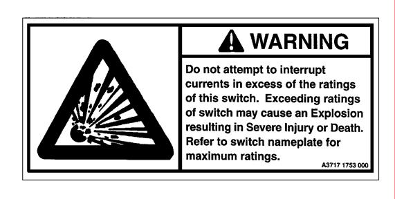
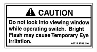
4 SECTION 2. SAFETY INFORMATION & PRECAUTIONS 2.1 Safety Alert Messages The following is important safety information. For safe installation and operation, be sure to read and understand all danger, warning and caution information. The various types of safety alert messages are described below: DANGER DANGER - Indicates an imminently hazardous situation which, if not avoided, will result in death or serious injury. - Indicates a potentially hazardous situation which, if not avoided, could result in death or serious injury. CAUTION CAUTION - Indicates a potentially hazardous situation which, if not avoided, may result in minor or moderate injury. May also be used to alert against unsafe practices. 2.2 Following Safety Instructions Carefully read all safety messages in this manual and on your equipment. Keep safety signs in good condition. Replace missing or damaged safety signs. Keep your equipment in proper working condition. Unauthorized modifications to the equipment may impair the function and/or safety and effect equipment life. If you do not understand any part of these safety instructions and need assistance, contact your G&W representative or G&W Customer Service. 2.3 Replacement Instruction and Labels Replacement instructions and safety labels are available from G&W. To obtain them, please contact Customer Service. 2.4 List and Location of Safety Labels The following are typical safety labels which must be followed. Refer to customer drawing in Section 9.1 for approximate location of the labels on the switch. The drawings represent typical configurations and may vary. Page 4 GWI , Rev. 6


5 Page 5 GWI , Rev. 6
6 2.5 X- Radiation Limits (if applicable) G&W Vacuum Interrupters and Fault Interrupters are designed and tested in accordance with applicable sections of ANSI/IEEE C37.60 and C37.85, which include the following information. Reference the above standards for more detailed information. The known United States manufacturers of vacuum interrupters initiated a test program during July of 1968 (as a Task Force of the NEMA Switchgear Section) to determine the present levels of X-radiation, if any, being emitted from high-voltage power vacuum interrupters, and to suggest permissible levels of radiation from such interrupters on the basis of their recognized application. Each manufacturer conducted a series of tests on new vacuum interrupters taken from stock and recorded the X- radiation levels, if any, under the following conditions: 1. Dielectric withstand test voltage applied to new interrupters 2. Fault current interruption (where applicable) 3. Load current interruption 4. Dielectric withstand test voltages after fault current interruption 5. Dielectric withstand test voltages after load current interruption As a result of evaluating the results of the aforementioned tests, the manufacturers concluded that neither the general public nor users will be subjected to harmful X-radiation due to normal application and operation of 15.5kV rated vacuum interrupter devices when applied within their assigned ratings and when the voltage applied across the open contacts of the interrupters is 15.5kV or less. Since the original 1972 adoption of this standard, manufactures have conducted tests on interrupters rated through 38kV, and data for these higher voltage interrupters was reflected in the 1989 edition of this standard. The testing and concurrent field experience has demonstrated that these higher voltage ratings meet the requirements of this standard. The 2002 revision of this document also adds data for interrupters rated below 15.5kV, to coordinate with the ratings of available apparatus. Precautions: If distances normally required for electrical safety are maintained, the exposure to test personnel will generally not exceed established dose limits (see ANSI N43.3). Nevertheless, adequate precautions such as shielding or distance should be used to protect test personnel against possible higher X-radiation occurrences due, for example, to incorrect contact spacing, or to the application of voltages in excess of those specified in Table 1, column 3. Table 1 - X-Radiation test voltages for interrupters applied without additional external shielding (Note 1) Rated Maximum Voltage (kv RMS) (note 1) (Col 1) X-radiation Test Voltages (Note2) Maximum Interrupter Operating Voltage (kv RMS) (Col 2) Power-Frequency Test Voltage (Col 3) (Note 3) 60.0 (Note 4) Notes: Page 6 GWI , Rev. 6
7 (1) Table 1 will be expanded in future revisions of this standard as additional ratings become available. (2) Refer to Appendix B (ANSI C37.85) for derivation of the test voltages. (3) For interrupters used in switchgear having a power-frequency withstand test voltage of 70kV rms. (4) For interrupters used in switchgear having a power-frequency withstand test voltage of 80kV rms. Page 7 GWI , Rev. 6
8 SECTION 3 SWITCH DESCRIPTION 3.1 General G&W manufactures a complete line of SF 6 switches for either load break, fault interrupting or a combination of load and fault interrupting switching. Pad mount, vault and overhead configurations are available. Switches are connected to cable systems using industry standard bushing and connectors. Switches can be operated either manually using a variety of operating handles or remotely using a motor actuator. A variety of electronic controls are available for local or remote operation. Refer to the outline drawing attached for identification and location of switch components for your particular switch style. Page 8 GWI , Rev. 6
9 SECTION 4 INSTALLATION This switch has been shipped factory filled with the proper amount of SF 6. If the switch has not maintained the proper pressure (refer to the table on the switch, located near the pressure gauge or Table 1, Section 6.2 or, if supplied with a temperature compensated pressure gauge, by ensuring indicator of pressure gauge is in green zone), do not install the switch. Follow the filling procedure in Section Handling Do not lift or handle switch by the bushings. Doing so may result in damage to the switch and possible injury or death to personnel. Use proper procedures meeting all applicable safety codes when lifting the switch. This may require the use of spreader bars, lifting beams, or other equipment to obtain a proper lift. Failure to use proper equipment and/or techniques to lift the switch may result in personal injury or death. The switch is equipped with lifting eyes or other lifting provisions. Use proper equipment to obtain a vertical lift without damaging the unit. See switch drawing in Section 9.1 for approximate weight and lifting provision details. 4.2 Mounting For vault and pad mount applications, provisions should be made for ample cable training space. All switches have provisions for mounting. See switch drawing in Section 9.1 for mounting details. Check that the switch, in its installed position, is secured and that mountings are adequate to support the weight of the switch. For applications that may be subject to flooding, the mountings must be capable of withstanding buoyant tendencies. 4.3 Grounding (earthing) Ground bosses are located on the switch tank. To ensure a good ground connection, the top surface of each boss must be sanded to expose bare metal before making a ground connection. The switch tank must be attached to a suitable ground as required by local practice. Ensure that all cable terminations for shielded cable have been properly grounded to the switch tank during installation. 4.4 Cable Connections Each entrance must be properly terminated. Entrances must be terminated following instructions supplied by the termination manufacturer. Switch entrances are designed to accept cable accessories constructed in accordance with IEEE 386 or a termination means specifically approved by G&W Electric Co. The use of any other cable termination means can present an electrical hazard or cause failure resulting in serious injury or death. Page 9 GWI , Rev. 6
10 DANGER End caps constructed in accordance with IEEE 386 or a termination means specifically approved by G&W Electric Co. must be used to cover any terminal connections that are not terminated to a cable. The shipping caps will not provide proper electrical insulation for an energized terminal. Energizing a non-terminated connection can present an electrical hazard or cause failure resulting in serious injury or death. 4.5 Installation Testing High potential testing on switches and cable systems may be conducted. Refer to Section 7, Testing. 4.6 Fault Indicators (if applicable) Refer to separate instructions. 4.7 Interrupter Controls (if applicable) Refer to separate instructions. 4.8 Voltage sensors (if applicable) Refer to separate instructions. 4.9 Actuators (if applicable) Refer to separate instructions Enclosure (if applicable) If supplied, pad mount enclosures provide tamper resistant construction. Penta-head bolts require a special wrench to open and are located on each access door. Door handles are supplied with a provision for padlocking. Wind stops are supplied for each door panel. Some enclosures are supplied with a flip-up top section that is locked in place behind the main access doors. Page 10 GWI , Rev. 6
11 SECTION 5 OPERATION 5.1 General Switches are assigned ratings by the manufacturer and have been designed and tested using levels established by ANSI and/or IEC standards. Design and production tests are conducted to demonstrate that the equipment will perform within the ratings on the nameplate and customer drawing. See Customer Drawing in Section 9.1. Equipment in service will perform to established ratings only if properly installed, operated and maintained. Power switchgear is characterized by high voltage and high continuous and short circuit currents. It should be installed, operated and maintained by Qualified Personnel. Failure to properly install, operate or maintain the equipment may result in damage to the switch and possible injury or death. For further information on operation and maintenance of equipment see ANSI C2 standards. Do not attempt to close into fault in excess of the switch ratings or to interrupt currents in excess of interrupting ratings. Either may result in damage to the switch and possible injury or death. At least once per year and before each operation, check the SF 6 pressure by comparing the pressure gauge to the table on the switch or in Section 6.2 or, if supplied with a temperature compensated pressure gauge, by ensuring indicator of pressure gauge is in green zone. Re-pressurize, if required, in accordance with Section 6.3. Do not operate an energized switch if the SF 6 gas pressure varies by more than 2 psig (14 kpa) from the Table 1, Section 6.2 or is red zone of temperature compensated pressure gauge. Check gauge pressure before operating the switch. Improper SF 6 gas pressure may cause the switch not to operate as designed, resulting in damage to the switch and possible injury or death. 5.2 Operation of the Rotary Puffer Switch Operators The following steps are for rotary puffer switches utilizing an insulated removable style-operating handle (Figure 1) The insulated removable style handle is designed for direct hand operation Verify the proper SF 6 pressure of the switch by viewing the pressure gauge on the tank and cross- referring the gas pressure/temperature Table 1, Section 6.2 of this instruction. The pressure/temperature chart is also located on the switch tank Verify rotary puffer contact position (OPEN or CLOSED) by viewing handle position. If the handle position is UP and the red mark on the handle coupling indicates OPEN, the contacts are open (Figures 1 and 2). If the handle position is DOWN and the red mark on the handle coupling indicates CLOSED, the contacts are closed (Figures 1 and 2). Page 11 GWI , Rev. 6
12 Also, the visible verification of contact position is possible by viewing through the viewing window. If the CLOSED label is shown on the rotor tube installed inside the plastic outer shell, the contacts are closed. If the OPEN label is shown, the contacts are open (Figure 3). The viewing window indicator and handle should be the same. Figure 2 RED MARK FOR INDICATION Figure To operate the switch, insert the insulated handle into the handle coupling and throw into the desired position. The handle will travel approximately 90 degrees from open to close. If the handle coupling is UP, the contacts are open (Figure 2). If the handle coupling is DOWN, the contacts are closed (Figure 2). The operating handle will travel approximately 90 degrees before the spring mechanism inside the switch tank is fully charged and unlatching occurs. At that point, the switch contacts move rapidly from one position to the next. Whether the operating handle is moved fast or slow is unimportant. The switch contacts will remain latched until released by the action of the spring mechanism. The contacts will latch in the new position when the switching action is complete. Avoid excessive force when manually operating. NOTE: The handle may over travel up to 15 degrees in either direction. This is normal for the operation and does not effect contact position. For safety, the mechanism provides positive position indication. The operating handle will return to its original position, signifying an incomplete operation if the switch contacts fail to move Check for successful operation by observing the position of the handle coupling and/or close/open label on the RP module shaft. The label is located inside switch tank and can be seen through the viewing window (Figure 3). Page 12 GWI , Rev. 6
13 Figure The coupling/handle assembly is equipped with provisions for padlocking in all positions. 5.3 Operation of the Three Phase FI Vacuum Interrupter (if applicable) The following steps are for FI three phase vacuum interrupters utilizing an insulated removable style operating handle (Figure 4). NOTE: The position of the three-phase vacuum interrupter handle (indicator) does not indicate switch contact position. Contact position is only verified by the OPEN-CLOSED indicator visible through the viewing window adjacent to each interrupter operating handle coupling. Figure The insulated removable style handle is designed for direct hand operation Verify the proper SF 6 pressure of the switch by viewing the pressure gauge on the tank and cross- referring the gas pressure/temperature Table 1, Section 6.2 of this instruction. The pressure/temperature chart is also located on the switch tank. Page 13 GWI , Rev. 6
14 Verify interrupter contact position (OPEN or CLOSED) by looking through the viewing window adjacent to the operating handle coupling If contact indicator reads CLOSED the operating handle will be in the down position. TO OPEN, insert the insulated handle into the handle coupling. Raise handle to the up position using a steady motion until movement stops (approximately 90 degrees from its original position). Make certain to raise the handle to the uppermost position even though you may hear the contacts open prior to that. Moving the handle to its end position is required to reset the VI mechanism for the next operation. Verify OPEN contact by looking at the contact indicator through the viewing window (Figure 5 and 6). Figure If the contact indicator reads OPEN the operating handle coupling may be in the up or down position. If the handle coupling position is up, it means that the vacuum interrupter has been manually opened. TO CLOSE: Depress handle to the downward position using a steady motion until movement stops (approximately 90 degrees from its original position). Verify CLOSED contact through viewing window (Figure 5 and 6). If the handle coupling position is down, it means that the vacuum interrupter has been electrically tripped. This was due to either an overcurrent condition or because the push-button (if provided) was operated on the electronic control. The electronic controls are located on the inside front access door of the enclosure. TO RESET: Verify that the cause of fault or overload is corrected. Raise handle to the up position using a steady motion until movement stops (approximately 90 degrees from its original position). Contact position should still indicate OPEN (Figure 5 and 6). Page 14 GWI , Rev. 6
15 Figure Operation of the Interrupter Controls The electronic control monitors the current and activates a trip solenoid, which opens the vacuum interrupter to interrupt overcurrents. The control is housed within a NEMA enclosure and are powered by current transformers mounted inside the switch tank. The controls are factory set for the current response curves if specified by the customer. Reference switch outline drawing and separate instructions on Vacuum Interrupter Controls for location and style of the controls supplied. Review the instructions for more detailed information. 5.5 Locking in a position Padlock provisions are provided. 5.6 Operation by actuator (if applicable) See supplemental instructions provided. 5.7 Automatic operation (if applicable) See supplemental instructions provided. 5.8 Fuses (if applicable) Some switches are equipped with dry well fuse holders for use with NX, ELX, CX or GP type current limiting fuses. Fuses are installed at the factory when they are ordered with the switch. The fuse holders are hook stick operable and can be mechanically interlocked with the switch to prevent access to the fuses when the switch is in the closed position. DANGER Fuse holders are not rated for load break or load make operation. Do not attempt to override the mechanical interlock to remove or replace fuses with the switch in the closed position. Always replace the fuse draw out rod and return the interlock to its closed and locked position prior to closing the switch. Fuse holders can contain energized parts even with the switch in the open position. Do not attempt to clean or probe inside of the fuse holders without completely de-energizing, grounding and isolating the switch in accordance with prescribed practices. Failure to follow these prescribed procedures can result in serious personal injury or death. Page 15 GWI , Rev. 6
16 SECTION 6 MAINTENANCE 6.1 General No internal maintenance is required. However, if the switch must be opened, personnel should be instructed to take certain precautions. During any internal maintenance, the switch must be de-energized. The SF 6 should be pumped from the switch through filters into a storage tank for reuse. CAUTION SF 6 removed from a switch should be pumped through a filter into a storage tank for reuse. SF 6 is heavier than air and will displace air (oxygen) in confined or low-lying areas. Make sure adequate ventilation is provided for enclosed or low-lying environments to prevent oxygen displacement and possible injury or death by asphyxiation. SF 6 has been identified as a greenhouse gas and should not be released into the atmosphere. Emissions of SF 6 may contribute to global warming. Occasional visual inspection of the switch is recommended and if possible, the switch(es) should be exercised periodically. At least once per year and before each operation, check the SF 6 pressure by comparing the pressure gauge to the table on the switch located near the pressure gauge or in Section 6.2 or, if supplied with a temperature compensating pressure gauge, by ensuring indicator of pressure gauge is in green zone. Re-pressurize if required in accordance with Section 6.3. A fitting is provided on the tank for the addition of SF 6. If leak detection becomes necessary, detectors are readily available which are sensitive to SF Table 1, SF 6 Pressure/Temperature Chart (for non temperature compensated pressure gauge) Ambient Temperature (1) Filling Pressure Ambient Temperature (1) Filling Pressure o C kpa o F psig (1) For ambient temperatures less than -20 o F (-30 o C) or in excess of 120 o F (50 o C) consult factory. Page 16 GWI , Rev. 6
17 Do not operate an energized switch if the SF 6 gas pressure varies by more than 2 psig (14 kpa) from the table above. Check gauge pressure before operating the switch. Improper SF 6 gas pressure may cause the switch not to operate as designed, resulting in damage to the switch and possible injury or death to personnel. CAUTION Fresh SF 6 gas is nonflammable and non-toxic but is heavier than air. Oxygen may be displaced in lowlying or enclosed environments. Make sure adequate ventilation is provided to prevent oxygen displacement and possible asphyxiation. 6.3 SF 6 Filling Procedure If it is suspected that the switch has lost some or all of its gas, follow this procedure to verify loss and properly refill the switch. Verify the switch pressure with a known gauge. This can be accomplished by connecting the known gauge to one end of a flexible hose suitable for pressure up to 15 psig or 103 kpa and connecting the other end to the switch fill valve. Two different types of fill valves have been used on G&W switches. One has a 1/4" NPT male connection and the other has a 1/4" SAE male flare connection. The fill valve with the 1/4" NPT male fitting is distinguished by its separate shutoff handle. Valves with the 1/4" SAE male flare connection have internal shut-offs which are activated by the hose connection fitting. Be sure to use the proper fittings for connecting to the fill valve. CAUTION Use of improper fittings can cause gas leakage leading to a complete loss of gas pressure. Complete loss of gas pressure can lead to a switch explosion resulting in serious injury and/or death If the switch has lost some gas but has maintained a positive pressure, it need not be de-energized or vacuumed before re-pressurizing with SF 6. Proceed to If the switch has not maintained a positive pressure de-energize immediately and follow the entire filling procedure beginning with 6.3.3, below If the switch tank has not maintained a positive pressure of at least 2 psig (14 kpa) or has otherwise been opened to ambient air, the switch tank should be purged. CAUTION Do not purge the switch while energized. Complete loss of SF 6 gas can lead to a switch explosion resulting in serious injury and/or death. The molecular sieve is located inside the switch tank in a plastic mesh. The switch tank may have to be cut open to replace the molecular sieve. Plastic gloves should be worn to prevent white powder by-products from coming in contact with skin as it may cause irritation. One end of the plastic mesh may be unfastened to allow removal of the bags. It is important to minimize exposure of the molecular sieve to moist atmospheric conditions. Page 17 GWI , Rev. 6
18 The molecular sieve is not listed in the U.S. EPA's Resource Conservation and Recover Act (RCRA) Hazardous Waste Management Regulations and does not possess any of the four identifying characteristics of hazardous waste. Dispose of the sieve and container in an environmentally acceptable manner, in full compliance with all applicable government regulations Remove the cap covering the valve, connect the vacuum pump, open the tank valve and evacuate the switch to between 29 and 30 inches of mercury at 60 o F ( kpa at 15.6 o C). Disconnect vacuum pump. Fill switch to 10 psig (79 kpa) with dry nitrogen having a dew point of less than -45 o C (-49 o F). CAUTION Do not pressurize the switch beyond 103 kpa or 15 psig. The tank has a maximum operating pressure of 103 kpa or 15 psig. Exceeding 15 psig or 103 kpa can lead to a switch explosion resulting in serious injury and/or death. After completing the fill, vent and re-vacuum to between 29 and 30 inches of mercury at 60 o F ( kpa at 15.6 o C). Disconnect vacuum pump. The switch is now purged Adjust the gas regulator to 20 psig (140 kpa) and allow a small volume of SF 6 to flow, purging air from the supply line prior to connecting the supply line to the switch. CAUTION Do not pressurize the switch beyond 103kPa or 15 psig. The tank has a maximum operating pressure of 103 kpa or 15 psig. Exceeding 15 psig or 103 kpa can lead to a switch explosion resulting in serious injury and/or death Remove the valve cap and make the connection to the switch. Re-pressurize the switch according to Table 1, Section 6.2. CAUTION Do not pressurize the switch beyond 103kPa or 15 psig. The tank has a maximum operating pressure of 103 kpa or 15 psig. Exceeding 15 psig or 103 kpa can lead to a switch explosion resulting in serious injury and/or death Once the switch is filled, stop the flow of SF 6, remove the filling line and replace the cap. 6.4 Handling of G&W SF 6 Switches Overview The following information is for reference as a general guideline when operating, performing maintenance or disposing of G&W Electric Sulfur Hexaflouride (SF 6 ) gas insulated switchgear. This information is compiled in accordance with existing industry papers on the subject (see reference section). It is difficult to anticipate all possible situations that may occur. Any questions on how to handle a specific situation should be forwarded to the local G&W Electric representative. State and local regulations should always be considered. Page 18 GWI , Rev. 6
19 CAUTION SF 6 gas venting from a switch should be pumped through a filter into a storage tank for reuse. SF 6 heavier than air and will displace air in confined or low-lying areas. Make sure adequate ventilation is provided for low-lying or enclosed environments to prevent oxygen displacement and possible asphyxiation General Information SF 6 gas has been used for many years in transmission cable systems and circuit breakers. The application versatility of the gas soon led to its use in distribution voltage ( kV) equipment. Although it is used as an insulating medium in both applications, there are some very important differences to consider. Primary considerations are the amount of SF 6 gas used in the equipment, typical operating pressures and the fault or load break energy associated with interruption Amount of Gas High voltage circuit breakers use large amount of gas, up to 2000 lbs. (800 kg) in some applications. G&W SF 6 switches use between 8-20 lbs. of gas Operating Pressure The pressure of SF 6 gas in any contained vessel will vary with temperature. G&W SF 6 switches require an operating pressure of approximately 8.5 psig at 60 o F (55 kpa at 10 o C) Fault or Load Break Energy High voltage circuit breakers re designed to interrupt typically high energy fault current within the SF 6 environment. G&W SF 6 load break switches are designed for typically 630 Amp load break operation. In accordance with industry standards, the switches also have a momentary and fault close rating typically in the ka asym. (32-64 ka peak) range. Arc interruption in SF 6 is therefore only a load break or low energy function, as opposed to a fault interrupting or high energy function. G&W switches designed for fault interrupting duty incorporate vacuum bottles or air insulated canister style fuses for these applications. All fault interruption is performed without the aid of SF 6 gas. Sulfur hexaflouride gas, in its virgin state, is a non-toxic, nonflammable, odorless and colorless gas. It combines excellent electrical, chemical and thermal properties making it an ideal dielectric. Included in these properties are high dielectric strength, excellent arc quenching capability, excellent chemical stability and good thermal conductivity. Although the gas has many advantages, there are certain precautions which should be considered when dealing with this dielectric Safety Precautions & By-products Sulfur hexaflouride has been described as a "physiologically inert gas". Laboratory rats have been exposed to a mixture of 80% SF 6 and 20% oxygen (the maximum concentration of gas possible without lowering the oxygen supply to an unsafe level) for periods of hours. The rats showed no signs of intoxication or irritation either during exposure or afterward. SF 6 is heavier than air and will accumulate in low lying areas. Because the gas is odorless, colorless and nonpoisonous, it cannot easily be detected without the use of proper equipment. The possibility of asphyxiation due to oxygen displacement needs to be considered. Proper gas detection instruments should be used. At very high temperatures or in the presence of an electric arc, SF 6 can be slowly decomposed. Decomposition products include lower fluorides of sulfur, which are hydrolyzable, yielding SO 2 and HF. Page 19 GWI , Rev. 6
20 Arced SF 6 in the presence of moisture may form potentially toxic by-products which can exist in both the gaseous and solid states. G&W uses the driest, highest grade SF 6 gas commercially available. G&W SF 6 switches have short arcing times, small volumes of dry SF 6 and contain a molecular sieve to absorb possible moisture and arc by-products thus minimizing the amount of by-products released. However, all SF 6 by-products should be considered potentially dangerous Solid By-products Tests have shown that arcing in SF 6 gas will produce solid by-products in the form of a fine dust or powder which consists of metal fluorides. These fluorides can be irritating and dangerous when in contact with skin or eyes. Contact with the podwer should be avoided. Also, precautions should be taken to avoid inhaling the powder. The powder particles are small and light enough to be suspended in air for substantial periods of time. This dictates the use of respirators or other protection to prevent inhaling the suspended particles when internal maintenance of the switch is required Gaseous By-products G&W has sampled the gas from a test switch to analyze the by-products. The switch was initially filled with approximately 13 pounds of SF 6 gas. The switch was operated 104 times under full load conditions (nominally 26 to 31 kv, 585 to 735 amps) and 30 times under loop circuit conditions (nominally, 5kV, 400 amps). The arc by-products and their concentrations resulting from these tests are in general agreement with those reported in other industry published papers and include SOF 2, CO 2, CF 4, and SO 2 F. SOF 2, thionyl fluoride, is the most highly concentrated arc by-product produced. SOF and SO 2 F are irritants to the respiratory tract and eyes. Fortunately, these gases are characterized by a pungent odor (rotten egg) noticeable in concentrations from 1 to 5 ppm. Industry reports indicate the lethal concentration for sixty minutes of exposure to SOF 2 is 100 ppm for rats and mice, and 500 ppm for rabbits. Carbon dioxide, CO 2, and carbon tetraflouride, CF 4 are considered nontoxic Recommended Precautions Vault or Enclosed Area Applications. In the unlikely event of a catastrophic switch failure which may cause the gas to be released to the environment, special precautions are necessary for vault or enclosed area applications. In this situation, toxic gases may accumulate and be present at dangerous levels. The gases that are produced will have a characteristic "rotten egg" odor. However, smell should not be used a s a test for the presence of by-products. The vault should be completely ventilated of all contaminated gases. If a vault has been purged, use a halogen type detector to test the air in the vault to determine if all SF 6 gas has been vented and sufficient oxygen is present. If all SF 6 has been vented, then the other gaseous by-products should have been removed at the same time. In any case, it is recommended that personnel entering the enclosed area be provided with air masks or rescue breathing apparatus. Self-contained oxygen masks should be used for maximum safety. (1) Above Ground Outdoor Applications. In the unlikely event of a catastrophic switch failure in above ground, applications, typically the gases would be dispersed into the atmosphere. Allow adequate time, approximately thirty minutes, depending on conditions, for this to occur before investigating the equipment Opening an SF 6 Switch for Disposal In order to dispose of a G&W SF 6 gas insulated switch, the switch must be opened. If the tank is still under pressure, the SF 6 must first be removed from the switch. This should be accomplished using suitable gas recovery equipment if at all possible. Alternately, the gas may be released to a well ventilated area where personnel will not be subject to possible arc by-products. One method might be to vent the gas through an absorber to neutralize any acid present. This can be accomplished using a hose on the fill valve of the tank. Air masks, breathing apparatus or, for maximum safety, self-contained oxygen masks should be provided for personnel if proper ventilation is not possible. Do not allow personnel to continually breathe gas that has an odor. Store the gas in suitable containers. Page 20 GWI , Rev. 6
21 Do not open any SF 6 filled equipment that has experienced arcing, corona or very high temperatures without taking adequate safety precautions to protect personnel from potentially hazardous solid and gaseous products. Since G&W SF 6 tanks are welded, it is necessary to grind or otherwise remove the weld off of the lid. This can be accomplished by grinding the weld filet flush and then chisel the remaining weld. This will minimize the possible spread of the solid by-products. Once the lid is removed, the exposed interior of the switch should be allowed to stand in a well ventilated area for at least thirty minutes in order for any retained gaseous by-products to dissipate. The use of gas detection equipment and proper protective clothing is recommended Internal Cleanup Although the amount of by-products should be minimal, personnel required to handle or remove the SF 6 solid by-products should wear skin protection equipment including disposable coveralls and gloves. Respiratory protection as previously described should also be worn. Any powder should be vacuumed (2) up or if possible wiped up with rags. The powder should be stored in an air tight metal container. The switch may have a light coating of white powder on the walls and components. These should be wiped down with a solution of sodium bicarbonate (baking soda). (3) The excess solution and rags should be disposed of with any powder previously collected. Parts with powder on them that cannot be reached should be disassembled and wiped down Disposal of Materials The tank and components that have been cleaned in the prescribed manner may be disposed of safely. The collected powder, solution and cleanup materials should be placed together in double plastic bags inside a metal container and have water added to cover them The ph of the solution should be checked. Solutions with a ph between 6 and 9 are generally suitable for normal disposal. If desired, soda carbonate (soda lime) (4) can be placed on top of the materials to neutralize the acidity. Emission of SF 6, or disposal of contaminated absorbents may be subject to environmental regulations. Users should review their operations in terms of applicable federal, state and local laws and regulations SF 6 General Guideline References 1. Study of Arc By-products in Gas Insulated Equipment. EPRI Report EL1646, Project SF 6 Gas Analysis Service. M J. Mastroianni & R. B. Jackson, Allied Chemical Corp. (Allied Signal) 3. Handling of SF 6 and Its Decomposition Products in Gas Insulated Switchgear (GIS). CIGRE Working Group 23.03, Electra No. 136 Part 1 dated June 1991 and Electra No. 137 Part 2 dated August Footnotes (1) Can be supplied from safety equipment manufacturers, e.g., Scott Aviation, a division of Figgie International Inc., 2225 Erie St., Lancaster, New York, 14086, USA Telephone (2) Can be supplied from safety equipment manufacturers, e.g. Nilfisk of America, Inc., 300 Technology Drive, Malvern, Pennsylvania, 19355, USA or equivalent. Telephone NIL - FISK. Page 21 GWI , Rev. 6
22 (3) Rule of thumb is dissolving 4 oz. (114 grams) of baking soda in one gallon (3.785 liters) of water. (4) Rule of thumb is dissolving approximately 2.5 lbs. ( kilograms) of sodium carbonate (soda lime) to 55 gallons ( liters) of water. 6.5 SF 6 Gas Specification SF 6 is made from two materials, sulfur and fluorine, which are in abundant supply. SF 6 is readily available from any of several suppliers. The use of commercial grade SF 6, per ASTM D2472, is recommended and may be obtained in cylinder sizes ranging from 6 to 115 pounds (2.714 to kilograms). Because high moisture content will affect the interrupting and dielectric properties of SF 6, cylinders should be sampled, testing dew point per ASTM D2029, before using. Simplified equipment for making this check is readily available. Cylinders whose dew point occurs above -45 o C (-49 o F) should be rejected. 6.6 Finish of Switch The switch paint finish is comprised of a two part epoxy, gray coating (Munsell No. 5BG7/0.4). Clean using soap and water. Touch up paint is available. 6.7 Repair Parts List Items such as operating handles, motor actuators, pressure gages, fill valves, shaft seals, bushings, gaskets, viewing windows, etc. are available from the factory if required. To inquire about spare or repair parts, contact G&W Representative or customer service with the switch serial number. 6.8 Returning Equipment to Service Make sure that the load interrupting and fault interrupting switches grounding means are removed Make certain the load interrupting and fault interrupting switches are in the correct position. If the switch operators are to be padlocked, do so at this time For padmounted switches, padlock the enclosure before leaving the area even momentarily. This should be done even if the switch is accessible only to qualified persons. Page 22 GWI , Rev. 6
23 SECTION 7 TESTING 7.1 Installation Testing Follow these precautions when performing electrical tests: 1. Completely de-energize the switch and disconnect it from all power sources. 2. Terminate all bushings with an insulated cap or other suitable cable termination capable of withstanding the test voltage. 3. Verify the SF 6 gas pressure is in accordance with Table X, Section 6.2. Failure to observe these precautions can result in flash over, injury and equipment damage. The DC withstand capability of switches may be reduced due to damage, gas leakage, or electrical or mechanical wear. The DC test voltage must not exceed the withstand limits of the switch. Application of DC voltages greater than the withstand capability of the switch can result in flash over, injury and equipment damage. CAUTION Do not pressurize the switch beyond 103kPa or 15 psig. The tank has a maximum operating pressure of 103 kpa or 15 psig. Exceeding 15 psig or 103 kpa can lead to a switch explosion resulting in serious injury and/or death. When it is necessary to test the cables connected to an energized switch, proper insulation between the power-frequency source and the DC test equipment must be maintained. Follow the recommendations of the manufacturer of the test or fault location equipment. DANGER Do not exceed the Maximum Dielectric Test Levels as shown in Section Exceeding the test levels can cause flash over. This can lead to a fault in the switch or test equipment and cause serious personal injury or death General After switches are completely installed in accordance with local practices, high voltage testing may be performed before the switch is energized. Test levels will generally be established by the cable or termination manufacturer but should not exceed the values listed in the tables below. Insure the test equipment is used in accordance with the manufacturer's instructions. Page 23 GWI , Rev. 6
24 7.1.2 Maximum Dielectric Test Levels: Switchgear Rating Withstand Test Voltage 50 Hz 60 Hz Impulse (BIL) Power Frequency DC 12kV N/A 75kV 28kV 35kV N/A 15.5kV 95kV 34kV 42kV 24kV 27kV 125kV 40kV 62kV 36kV 38kV 150kV 50kV 82kV 7.2 Cable Testing DC testing is primarily used to test the integrity of installed cable systems and terminations. DC testing should be performed in accordance with appropriate cable test standards, and must not exceed the rating of the switch. DC testing cables installed on switches must only be performed when all ways of the switch and cables are isolated from all system voltages. Applying a DC test voltage to a switch with energized ways may lead to electrical failure of the switch resulting in personnel injury or death. Testing of switches with internal potential transformers must not exceed the rating of the transformer. Applying a test voltage in excess of the transformer rating may damage the transformer leading to electrical failure of the switch which could result in personnel injury or death Maximum Cable Testing Levels: Switchgear Rating Cable Testing Cable Thumping 50 Hz 60 Hz Impulse (BIL) Power Frequency DC 12kV 15.5kV 95kV 30kV 15kV 24kV 27kV 125kV 40kV 20kV 36kV 38kV 150kV 40kV 20kV 7.3 Factory Production Tests Routine (production) tests are conducted in accordance with applicable standards. The following are typical production tests performed. Loadbreak Switches: - Circuit Resistance Test - Dielectric Test (60hz Withstand Test) - Tightness Test (Leak Test) - Design and Visual Checks (Operating Assurance Test) Page 24 GWI , Rev. 6
25 Fault Interrupters: - Circuit Resistance Test - Dielectric Test (60hz Withstand Test) - Tightness Test (Leak Test) - Design and Visual Checks (Operating Assurance Test) - Calibration of Minimum Power Up Level and Time Current Tests - Control and Secondary Wiring Tests 7.4 Interrupter Testing G&W can supply an optional tester to verify the proper operation of the fault interrupter electronics. Contact your G&W representative for further information. Page 25 GWI , Rev. 6
GWI Rev. 6 April, 2009 Supersedes Rev. 5 Dated November, 2004
 INSTALLATION, OPERATION AND MAINTENANCE INSTRUCTIONS ROTARY PUFFER SWITCHES Vault and Padmount Styles GWI 527-24 Rev. 6 April, 2009 Supersedes Rev. 5 Dated November, 2004 Table of Contents SECTION 1: Introduction
SUBSTATION MAINTENANCE ELECTRICAL OPERATING PROCEDURE
 Page 1 of 6 A. PURPOSE AND SCOPE This procedure establishes safe working practices for handling sulfur hexafluoride (SF 6 ) gas and release minimization practices. This document also specifies methods
Inspection Recommendations
 S&C Vista SD Underground Distribution Switchgear Pad-Mounted and Vault-Mounted Styles Outdoor Distribution (17.5 kv and 29 kv) With Visi-Gap Load Interrupter Switches and Visi-Gap Fault Inetrrupters Inspection
DEH Instructions. Three-Phase, Platform-Mounted Distribution Transformers
 g DEH 40050 Instructions Three-Phase, Platform-Mounted Distribution Transformers Introduction The equipment covered by these instructions should be operated and serviced only by competent technicians familiar
COOPER POWER SERIES. VFI SF6-insulated vacuum fault interrupter installation, operation and maintenance instructions. Switchgear MN285004EN
 Switchgear MN285004EN Effective October 2015 Supersedes S285-10-2 August 2005 COOPER POWER SERIES VFI SF6-insulated vacuum fault interrupter installation, operation and maintenance instructions DISCLAIMER
Environmental and Safety Concerns with SF 6 Gas
 DILO 2 nd Annual SF6 Gas Management Seminar Tampa FL, November 2017 Environmental and Safety Concerns with SF 6 Gas Patrick Di Lillo Technical Specialist Consolidated Edison Co. of NY, Inc. November 16,
TABLE OF CONTENTS PART 2 - CONFINED SPACES
 May 11, 2006 TABLE OF CONTENTS PART 2 - CONFINED SPACES Page DEFINITIONS... 2-1 GENERAL... 2-2 RESPONSIBILITIES... 2-2 HAZARD ASSESSMENT AND WORK PROCEDURES... 2-3 IDENTIFICATION AND ENTRY PERMITS... 2-3
Type CAP. CapSwitcher. Capacitor Switching Device kv 38 kv INSTALLATION & INSTRUCTION MANUAL
 Type CAP CapSwitcher Capacitor Switching Device 15.5 kv 38 kv INSTALLATION & INSTRUCTION MANUAL Safety Information DANGER THE EQUIPMENT COVERED IN THIS MANUAL SHOULD BE HANDLED, INSTALLED, AND MAINTAINED
Distribution Transformer Instruction Manual
 Distribution Transformer Instruction Manual TABLE OF CONTENTS SHIPPING.. 3 INSPECTION ON RECEIPT 3 HANDLING.. 4 INTERNAL INSPECTION 5 STORAGE.. 6 LOCATION 6 PREPARING FOR SERVICE 7 PUTTING INTO SERVICE
! Warning, refer to accompanying documents.
 About this Manual To the best of our knowledge and at the time written, the information contained in this document is technically correct and the procedures accurate and adequate to operate this instrument
STANDARD OPERATING PROCEDURE
 TO BE USED BY PROPERLY TRAINED AND AUTHORIZED PERSONNEL ONLY This document serves as a guide for the probable hazards of this space and how to remediate those hazards. It is important to remember that
200 A, 15 and 25 kv class loadbreak bushing insert installation instructions
 Loadbreak Apparatus Connectors Effective October 2013 Supersedes March 2011 200 A, 15 and 25 kv class loadbreak bushing insert installation instructions S500-12-1 DISCLAIMER OF WARRANTIES AND LIMITATION
Key Technology, Inc. Confined Space Entry Program. July, 2017
 Key Technology, Inc. Confined Space Entry Program July, 2017 Page 1 of 11 Key Technology, Inc. CONFINED SPACE ENTRY PROGRAM OVERVIEW Purpose: The purpose of this program is to ensure the protection of
Energy Control. Suite 2A, 55 Frid Street Hamilton, ON L8P 4M3 office: cell:
 Energy Control Suite 2A, 55 Frid Street Hamilton, ON L8P 4M3 office: 905.577.0303 cell: 905.977.0210 consultant@staffaid.ca www.staffaid.com Safety, Energy Control, Power Lockout & Function Test Procedures
COOPER POWER SERIES. Under-oil arrester disconnector installation/operation instructions. OEM Equipment MN800010EN
 OEM Equipment MN800010EN Effective February 2016 Supersedes S800-51-1 August 2012 COOPER POWER SERIES Under-oil arrester disconnector installation/operation instructions DISCLAIMER OF WARRANTIES AND LIMITATION
COOPER POWER SERIES. 200 A 15, 25, and 35 kv class portable feedthru installation instructions. Loadbreak Apparatus Connectors MN650037EN
 Loadbreak Apparatus Connectors MN650037EN Effective November 2016 Supersedes October 2013 (S500-14-1) 200 A 15, 25, and 35 kv class portable feedthru installation instructions COOPER POWER SERIES DISCLAIMER
TANK MANAGER FOR TWO TANKS OPERATING MANUAL. 10/31/11 C-More T6C L color touch panel
 TANK MANAGER FOR TWO TANKS OPERATING MANUAL 10/31/11 C-More T6C L color touch panel 1 TABLE OF CONTENTS GENERAL...3 INSTALLATION...4 STONE TEST PROCEDURE...7 OPERATIONAL SUMMARY...7 AUTO CARBONATION...10
Effective May 2017 Supersedes August 2005 (S )
") Padmounted Switchgear MN285013EN Effective May 2017 Supersedes August 2005 (S285-15-1) COOPER POWER Type shrubline VFI, vacuum fault interrupter; installation, operation and maintenance instructions SERIES
Padmounted Switchgear MN285013EN Effective May 2017 Supersedes August 2005 (S285-15-1) COOPER POWER Type shrubline VFI, vacuum fault interrupter; installation, operation and maintenance instructions SERIES
2 Sentry MCL Installation, Operation & Maintenance
 Gas Liquid & Slurry Solid & Powder Steam & Water Installation, Operation & Maintenance Manual Original Instructions Liquid Sampling Manual Low-Emission Samplers S-GA-IOM-00249-7 11-17 Sentry MCL 966 Blue
Safety Powder Spray Systems
 Instruction Sheet P/N 107 952C Safety Powder Spray Systems 1. Introduction This section contains general safety instructions for using your Nordson equipment. Task- and equipment-specific warnings are
New AQF Filter Polymer Filtration System
 New AQF Filter Polymer Filtration System Operator Manual Covering Serial Number 20002001 onwards February 2011 Index Disclaimer notice...3 Introduction...4 Important safety notices...5 Getting started...6
Selection of Electrical PPE Tables
 Selection of Electrical PPE Tables Instructions Table 1 - Starting with Table 1, select the task you plan to do (right-hand column) and the condition of the equipment you will be working on, (center column).
COOPER POWER SERIES. Manual or Hostick Operable, Padlockable 150 A Tap-Changer Switch Installation Instructions. Tap-Changer Switch MN800015EN
 Tap-Changer Switch MN800015EN Effective December 2017 Supersedes February 1987 (S800-58) COOPER POWER SERIES Manual or Hostick Operable, Padlockable 150 A Tap-Changer Switch Installation Instructions DISCLAIMER
Installation. S&C Vista Underground Distribution Switchgear. UnderCover, Vault-Mounted, and Pad-Mounted Styles. Instruction Sheet
 S&C Vista Underground Distribution Switchgear UnderCover, Vault-Mounted, and Pad-Mounted Styles Installation Table of Contents Section Page Section Page Introduction Qualified Persons.... 2 Read this Instruction
TEMPLE UNIVERSITY ENVIRONMENTAL HEALTH AND RADIATION SAFETY
 Page 1 of 9 ISSUED: 5/00 REVISED: 08/06 Introduction Purpose: In accordance with applicable regulations and Temple University, this policy was developed to minimize exposure to Ethylene Oxide. Applicability
ANNEX AMENDMENTS TO THE INTERNATIONAL CODE FOR FIRE SAFETY SYSTEMS (FSS CODE) CHAPTER 15 INERT GAS SYSTEMS
 CHAPTER 15 INERT GAS SYSTEMS") Annex 3, page 2 ANNEX AMENDMENTS TO THE INTERNATIONAL CODE FOR FIRE SAFETY SYSTEMS (FSS CODE) CHAPTER 15 INERT GAS SYSTEMS The text of existing chapter 15 is replaced by the following: "1 Application This
Annex 3, page 2 ANNEX AMENDMENTS TO THE INTERNATIONAL CODE FOR FIRE SAFETY SYSTEMS (FSS CODE) CHAPTER 15 INERT GAS SYSTEMS The text of existing chapter 15 is replaced by the following: "1 Application This
JANIS OPERATING INSTRUCTIONS FOR SUPERCONDUCTING MAGNET CRYOSTATS
 OPERATING INSTRUCTIONS FOR SUPERCONDUCTING MAGNET CRYOSTATS INTRODUCTION The Janis Research Company's Superconducting Magnet/Cryostat System is one of the most versatile tools available to the scientist
MISSOURI UNIVERSITY OF SCIENCE & TECHNOLOGY Procedure: 3.6
 Procedure This electrical safety procedure structures safety procedures to meet the requirements of the NFPA-70E Standard. The program is designed for qualified employees who occasionally must perform
Operating Manual. Model 25200B/25202B Refrigerant Recovery Unit. (Not for use in automotive R-134a applications)
") Operating Manual Model 25200B/25202B Refrigerant Recovery Unit (Not for use in automotive R-134a applications) ROBINAIR Refrigerant Recovery Unit Model: 25200B /25202B Series Type of Equipment: Recovery
Operating Manual Model 25200B/25202B Refrigerant Recovery Unit (Not for use in automotive R-134a applications) ROBINAIR Refrigerant Recovery Unit Model: 25200B /25202B Series Type of Equipment: Recovery
GAS FUEL VALVE FORM AGV5 OM 8-03
 ALTRONIC AGV5 OPERATING MANUAL GAS FUEL VALVE FORM AGV5 OM 8-03 WARNING: DEVIATION FROM THESE INSTALLATION INSTRUCTIONS MAY LEAD TO IMPROPER ENGINE OPERATION WHICH COULD CAUSE PERSONAL INJURY TO OPERATORS
MODEL 154XST INSTALLATION AND SERVICE INSTRUCTIONS FOR MODEL 154XST STROBE LIGHT FOR USE IN HARSH ENVIRONMENTS/ HAZARDOUS LOCATIONS
 MODEL 154XST INSTALLATION AND SERVICE INSTRUCTIONS FOR MODEL 154XST STROBE LIGHT FOR USE IN HARSH ENVIRONMENTS/ HAZARDOUS LOCATIONS 2561762B REV. B 210 Printed in U.S.A. INSTALLATION AND SERVICE INSTRUCTIONS
For use with select HPC Fire Pits ONLY- refer to product catalog or website. 100K BTU Maximum WARNING: FOR OUTDOOR USE ONLY
 For use with select HPC Fire Pits ONLY- refer to product catalog or website. 100K BTU Maximum : FOR OUTDOOR USE ONLY Small Tank LP Kit (STLPK) Installation & Operation Instructions Installation We suggest
200 PSI HIGH-FLOW AIR SOURCE KIT
 200 PSI HIGH-FLOW AIR SOURCE KIT 50% Duty Compressor on 2.0 Gallon Air Tank PART NO. 20008 IMPORTANT: It is essential that you and any other operator of this product read and understand the contents of
S Surge Arresters
 Surge Arresters UltraSIL Polymer-Housed VariSTAR Type US, UH, and UX Station-Class Surge Arresters Installation and Maintenance Instructions Service Information S235-88-1 Contents Product Information...........................1
Basic & Controlled Atmosphere Glove Boxes
 I N T R O D U C T I O N Precise Basic and Controlled Atmosphere Glove Boxes provide a leak-tight environment for work with contamination-sensitive materials. Precise Basic Glove Boxes are simple, economical
200 PSI FAST-FILL AIR SOURCE KIT
 200 PSI FAST-FILL AIR SOURCE KIT 55% Duty Compressor on 2.0 Gallon Air Tank PART NO. 20007 IMPORTANT: It is essential that you and any other operator of this product read and understand the contents of
HEALTH AND SAFETY MANUAL
 HEALTH AND SAFETY MANUAL Title: Hydrogen Sulfide (H 2 S) Safety Approved by: Greg Savoy Rev. 4/1/08 1 Purpose/Scope: The purpose of this program is to establish minimum requirements for site specific H
PERMIT-REQUIRED CONFINED SPACES PROGRAM
 PERMIT-REQUIRED CONFINED SPACES PROGRAM On January 14, 1993, OSHA established safety requirements to protect employees from the hazards of entry into permit-required confined spaces. It is essential to
BGA244 Binary Gas Analyzer
 Quick Start Guide Revision 1.0 Certification Warranty Service certifies that this product met its published specification at the time of shipment. This product is warranted against defects in materials
SAFETY AND HEALTH STANDARD CONFINED SPACE ENTRY REQUIREMENTS Effective Date: 06/10/10 Standard: 16.2 Document Number: KUCSH0038 Rev: 07
 16.2.1 INTRODUCTION 16.2.1.1 The purpose of this standard is to establish safety requirements, which include a permit system, for entry into confined spaces. 16.2.2 DEFINITIONS 16.6.2.1 Confined space
MODEL NUMBER: PSI AIR SOURCE KIT 200 PSI Compressor on 2.0 Gallon 200 PSI Air Tank
 IMPORTANT SAFETY INSTRUCTIONS CAUTION - To reduce risk of electrical shock or Electrocution: MODEL NUMBER: 20008 200 PSI AIR SOURCE KIT 200 PSI Compressor on 2.0 Gallon 200 PSI Air Tank IMPORTANT: It is
PremAire INSTRUCTIONS FOR VORTEX TUBE MODE OF OPERATION
 DUAL SUPPLY REGULATOR ESCAPE CYLINDER VORTEX MAIN INLET PremAire INSTRUCTIONS FOR VORTEX TUBE MODE OF OPERATION WARNING THIS MANUAL MUST BE READ CAREFULLY BY ALL PERSONS WHO HAVE OR WILL HAVE THE RESPONSIBILITY
COOPER POWER SERIES. EL Bay-O-Net Current-Limiting Fuse Installation Instructions. Fusing Equipment MN132023EN
 Fusing Equipment MN132023EN Effective November 2016 Supersedes June 2010 (S240-70-1) EL Bay-O-Net Current-Limiting Fuse Installation Instructions COOPER POWER SERIES DISCLAIMER OF WARRANTIES AND LIMITATION
Respiratory Protection
 Respiratory Protection Purpose The purpose is to establish a set of guidelines for the selection of respiratory protection equipment, situations for its use, and training in the use of the respirator required.
BP OIL -- TOLEDO REFINERY
 Document Type: Procedure BP OIL -- TOLEDO REFINERY Refinery Wide Procedure No.: SAF 086 Effective Date: May 9, 2016 Use of Nitrogen (N 2 ) Rev. No.: 9 Owner: Emily Stewart Auth. By: Chris Conley (Signature
COOPER POWER SERIES. 600 A, 15, 25, and 35 kv Class Cleer Grounding Elbow Installation Instructions. Loadbreak Apparatus Connectors MN650056EN
 Loadbreak Apparatus Connectors MN650056EN Effective July 2018 Supersedes May 2017 COOPER POWER SERIES 600 A, 15, 25, and 35 kv Class Cleer Grounding Elbow Installation Instructions DISCLAIMER OF WARRANTIES
1 Exam Prep NFPA 99 Health Care Facilities Questions and Answers (Plumbing Contractor)
") 1 Exam Prep NFPA 99 Health Care Facilities Questions and Answers (Plumbing Contractor) 1. According to NFPA 99, SCFM is an acronym for. a) Surface Conditions at Fahrenheit Mercury b) Standard Conditions
1 Exam Prep NFPA 99 Health Care Facilities Questions and Answers (Plumbing Contractor) 1. According to NFPA 99, SCFM is an acronym for. a) Surface Conditions at Fahrenheit Mercury b) Standard Conditions
Original Date of Issue: 04/09
 POLICIES AND PROCEDURES DEPARTMENT: Environmental Health and Safety SUBJECT: Electrical Safety Program Original Date of Issue: 04/09 Reviewed 12/2011 Revised 12/2011 BACKGROUND ELECTRIC SHOCK It is well
COOPER POWER SERIES. 200 A 15, 25, and 35 KV class insulated standoff bushing installation instructions. Loadbreak Apparatus Connectors MN650039EN
 Loadbreak Apparatus Connectors MN650039EN Effective November 2016 Supersedes October 2013 (S500-22-1) COOPER POWER 200 A 15, 25, and 35 KV class insulated standoff bushing installation instructions SERIES
Doc No: WELDHOT Midland Engineering Co., Inc. Initial Issue Date 12/14/15 Safety Management System
 Revision Preparation: Safety Mgr Authority: President Issuing Dept: Safety Page: Page 1 of 7 PURPOSE To provide guidelines for the safe operation of welding, cutting and hot work of equipment, and to itemize
ELECTRICAL (COMPREHENSIVE) SAFETY PROGRAM REGULATORY STANDARD: OSHA - 29 CFR CFR , ,
 SAFETY PROGRAM REGULATORY STANDARD: OSHA - 29 CFR CFR , ,") ELECTRICAL (COMPREHENSIVE) SAFETY PROGRAM REGULATORY STANDARD: OSHA - 29 CFR 1910.331 335-29 CFR 1926.302, 1926.416, 1926.417 BASIS: The National Safety Council estimates that there are at least 300 deaths
ELECTRICAL (COMPREHENSIVE) SAFETY PROGRAM REGULATORY STANDARD: OSHA - 29 CFR 1910.331 335-29 CFR 1926.302, 1926.416, 1926.417 BASIS: The National Safety Council estimates that there are at least 300 deaths
CAPITAL CONTROLS SERIES NXT3000
 CAPITAL CONTROLS SERIES NXT3000 Modular design gas feed system with self contained automatic switchover capability. The Series NXT3000 Gas Feed System is a family of vacuumoperated, solution-feed gas dispensing
OxyCheq Expedition-X Oxygen Analyzer. Operator s Manual
 OxyCheq Expedition-X Oxygen Analyzer Operator s Manual OxyCheq 3528 Russell Road Marianna, Florida 32446 USA Tel: 850.482.0385 Email: oxy@oxycheq.com Web: http://oxycheq.com CONTENTS 1.0 Introduction..
COOPER POWER SERIES. D-73P3 bypass switches installation instructions. Switches MN008005EN. Effective April 2016 Supersedes S June 2013
 Switches MN008005EN Effective April 2016 Supersedes S328-120-1 June 2013 D-73P3 bypass switches installation instructions COOPER POWER SERIES DISCLAIMER OF WARRANTIES AND LIMITATION OF LIABILITY The information,
36H SERIES Combination Gas Valve
 FAILURE TO READ AND FOLLOW ALL INSTRUCTIONS CAREFULLY BEFORE INSTALLING OR OPERATING THIS CONTROL COULD CAUSE PERSONAL INJURY AND/OR PROPERTY DAMAGE. DESCRIPTION The 36H series combination gas valve is
Cal/OSHA T8 CCR 1536 Cal/OSHA T8 CCR 4799 Cal/OSHA T8 CCR 4845 Cal/OSHA T8 CCR 4848
 Cal/OSHA Gas Systems for Welding GAS WELDING Cal/OSHA T8 CCR 1536 Cal/OSHA T8 CCR 4799 Cal/OSHA T8 CCR 4845 Cal/OSHA T8 CCR 4848 When performing gas welding, the following precautions, work procedures,
MANUAL DIRECT PURGE OPTION. UNION Instruments GmbH CWD2005 PLUS. General information, safety standards and regulations for direct purge option
 MANUAL DIRECT PURGE OPTION UNION Instruments GmbH CWD2005 PLUS General information, safety standards and regulations for direct purge option Version: V1.00 Stand: 24.03.2010 Union Instruments GmbH Zeppelinstr.
Capital Controls Series NXT3000 Modular design gas feed system with self-contained automatic switchover capability.
 Capital Controls Series NXT3000 Modular design gas feed system with self-contained automatic switchover capability. The Series NXT3000 Gas Feed System is a family of vacuum-operated, solution-feed gas
Lockout / Tagout Safety Program
 Lockout / Tagout Safety Program Prepared by: The Ohio State University Environmental Health and Safety Occupational Safety & Industrial Hygiene 1314 Kinnear Road Columbus, OH 43212-1168 614-292-1284 Phone
COOPER POWER SERIES. 50 A 2:1 series multiple (dual voltage) switch cap/wrench, lever or hotstick operable handles installation instructions
 switch cap/wrench, lever or hotstick operable handles installation instructions") Voltage Regulators MN800013EN Effective February 2016 Supersedes S800-70-1 August 2012 COOPER POWER SERIES 50 A 2:1 series multiple (dual voltage) switch cap/wrench, lever or hotstick operable handles
Voltage Regulators MN800013EN Effective February 2016 Supersedes S800-70-1 August 2012 COOPER POWER SERIES 50 A 2:1 series multiple (dual voltage) switch cap/wrench, lever or hotstick operable handles
97C COMPRESSOR KIT 12V PART NO C COMPRESSOR KIT 24V PART NO C COMPRESSOR KIT PART NO
 97C COMPRESSOR KIT 12V PART NO. 00097 97C COMPRESSOR KIT 24V PART NO. 02497 98C COMPRESSOR KIT PART NO. 00098 97C 98C IMPORTANT: It is essential that you and any other operator of this product read and
Columbus Instruments
 0215-003M Portable O 2 /CO 2 /CH 4 Meter User s Manual Columbus Instruments 950 NORTH HAGUE AVENUE TEL:(614) 276-0861 COLUMBUS, OHIO 43204, USA FAX:(614) 276-0529 1 www.colinst.com TOLL FREE 1-800-669-5011
Entry to these spaces must be rigorously controlled to prevent serious injury or death.
 Chapter 6 - Confined Spaces Chapter 6 Confined Spaces Definitions A confined space is defined as any structure that must be entered and that has or may contain dangerous concentrations of hazardous gases
3 GALLON, OILLESS PANCAKE COMPRESSOR INSTRUCTIONS. Item #31289
 3 GALLON, OILLESS PANCAKE COMPRESSOR INSTRUCTIONS Item #31289 The EASTWOOD 3 GALLON, OILLESS PANCAKE COMPRESSOR, with an Integral Air Regulator, efficiently supplies all compressed air requirements for
36E DSI, HSI & Proven Pilot Two-Stage Combination Gas Valve INSTALLATION INSTRUCTIONS
 INLET PRESS TAP WTE-RODGERS 36E96-314 DSI, HSI & Proven Pilot Two-Stage Combination Gas Valve INSTALLATION INSTRUCTIONS Operator: Save these instructions for future use! FAILURE TO READ AND FOLLOW ALL
Safety Tips from the WorkSafe People. Building a Safety Program for Your Organization
 Building a Safety Program for Your Organization 1 Content Criteria and Examples of Confined Spaces Permit-Required Confined Space Non-Permit-Required Confined Space Employer Requirements Employee Requirements
Accu-Tab Systems 1000 Series by Axiall Corporation
 Accu-Tab Systems 1000 Series by Axiall Corporation Installation and Operating Instructions Model 1050 DANGER: DO NOT MIX CHEMICALS! The Accu-Tab chlorinator is designed for use with Axiall approved tablets
MODEL NUMBER: M20005 AIR SOURCE KIT. 30% Duty Compressor on. 2.0 Gallon Air Tank SAVE THIS MANUAL FOR FUTURE REFERENCE
 MODEL NUMBER: M20005 AIR SOURCE KIT 30% Duty Compressor on 2.0 Gallon Air Tank SAVE THIS MANUAL FOR FUTURE REFERENCE USER MANUAL IMPORTANT SAFETY INSTRUCTIONS CAUTION - To reduce risk of electrical shock
Field Instruction Storage, Handling, Transport and Disposal of Sulphur Hexafluoride (SF6) Gas
 Gas") 6.14 Storage, Handling, Transport and Disposal of Sulphur Hexafluoride (SF6) Gas Purpose Describe the minimum requirements for safe handling, storage, maintenance, repair, transport and disposal of equipment
6.14 Storage, Handling, Transport and Disposal of Sulphur Hexafluoride (SF6) Gas Purpose Describe the minimum requirements for safe handling, storage, maintenance, repair, transport and disposal of equipment
Information Sheet. About this information sheet. Floor and wall loadings. Attachment of process module to floor. PlasmaPro Estrelas100
 Information Sheet PlasmaPro Estrelas100 About this information sheet This data sheet provides basic information about the installation of a PlasmaPro Estrelas100 tool. Some of the information in this sheet
PRS(TC)4,8 USER MANUAL. Read the complete manual before installing and using the regulator.
4,8 USER MANUAL. Read the complete manual before installing and using the regulator.") PRS(TC)4,8 USER MANUAL Read the complete manual before installing and using the regulator. WARNING INCORRECT OR IMPROPER USE OF THIS PRODUCT CAN CAUSE SERIOUS PERSONAL INJURY AND PROPERTY DAMAGE. Due to
PRS(TC)4,8 USER MANUAL Read the complete manual before installing and using the regulator. WARNING INCORRECT OR IMPROPER USE OF THIS PRODUCT CAN CAUSE SERIOUS PERSONAL INJURY AND PROPERTY DAMAGE. Due to
This test shall be carried out on all vehicles equipped with open type traction batteries.
 5.4. Determination of hydrogen emissions page 1 RESS-6-15 5.4.1. This test shall be carried out on all vehicles equipped with open type traction batteries. 5.4.2. The test shall be conducted following
RISK ENGINEERING TECHNICAL GUIDE
 Introduction Many workspaces contain spaces that are considered to be "confined", because their configurations hinders the activities of any employee who must enter into, work in, and exit from them. In
Neil Kane Managing Director EMT UK
 Neil Kane Managing Director EMT UK SF6 Measurement, Analysis, Diagnostics and Leak Detection Our goals at EMT are to supply Maintenance Operatives with the very best tools to protect both personnel and
Welding With Arc Welding Equipment
 Optional Information Name of School: Date of Inspection: Vocational Program/Course/Room: Signature of Inspector: Welding With Arc Welding Equipment Self Inspection Checklist Guidelines: This checklist
A. Evaluation of the written program
 A. Evaluation of the written program Begin your audit with an evaluation of the written respiratory protection program. In addition to the operating procedures describing respirator selection and use in
COLD-WEATHER APPLICATION OF GAS MIXTURE (SF 6 /N 2, SF 6 /CF 4 ) CIRCUIT BREAKERS: A UTILITY USER S PERSPECTIVE SUMMARY
 CIRCUIT BREAKERS: A UTILITY USER S PERSPECTIVE SUMMARY") COLD-WEATHER APPLICATION OF GAS MIXTURE (SF 6 /N 2, SF 6 /CF 4 ) CIRCUIT BREAKERS: A UTILITY USER S PERSPECTIVE R. L. Middleton, P. Eng. Manitoba Hydro, Winnipeg, Canada SUMMARY Very low temperatures stress
COLD-WEATHER APPLICATION OF GAS MIXTURE (SF 6 /N 2, SF 6 /CF 4 ) CIRCUIT BREAKERS: A UTILITY USER S PERSPECTIVE R. L. Middleton, P. Eng. Manitoba Hydro, Winnipeg, Canada SUMMARY Very low temperatures stress
TECHNICAL DATA. Trimpac 257a. September 16, 2013
 September 16, 2013 Trimpac 257a 1. DESCrIpTION DESCRIPTION The Viking Double SUREFIRE SIngle Interlock Preaction TRIMPAC Model D-2 and D-2B used with either a Model E or F Deluge Valve (A.1), a Viking
RDK-408D2 Cold Head. Technical Manual. SHI-APD Cryogenics Inc Vultee Street Allentown, PA U.S.A. Revision A: September 2005
 RDK-408D2 Cold Head Technical Manual SHI-APD Cryogenics Inc. 1833 Vultee Street Allentown, PA 18103-4783 U.S.A. Revision A: September 2005 (Reference SHI Manual: December 18, 2003 266404A CD32ZZ-160A)
IMPORTANT SAFETY INSTRUCTIONS
 IMPORTANT SAFETY INSTRUCTIONS CAUTION - To reduce risk of electrical shock: - Do not disassemble. Do not attempt repairs or modifications. Refer to qualified service agencies for all service and repairs.
CONFINED SPACE ENTRY PROGRAM FOR GOUCHER COLLEGE
 I. INTRODUCTION CONFINED SPACE ENTRY PROGRAM FOR GOUCHER COLLEGE The Goucher College campus has confined spaces that, due to various chemical and physical properties, may cause death or serious injury
VERTICAL AIR COMPRESSORS
 VERTICAL AIR COMPRESSORS MODEL NO: VE15C150, VE18C150, VE25C150 PART NO: 2226010, 2226020, 2226025 OPERATION & MAINTENANCE INSTRUCTIONS LS0715 INTRODUCTION Thank you for purchasing this CLARKE Vertical
Confined Space Program
 Insert City Name Page 1 of 6 Purpose Regularly, confined spaces must be entered for inspection, cleaning or repair. Such spaces can present unusual hazards such as lack of sufficient oxygen, special mechanical
36E DSI and HSI Two-Stage Combination Gas Valve INSTALLATION INSTRUCTIONS
 INLET PRESS TAP WTE-RODGERS 36E54-214 DSI and HSI Two-Stage Combination Gas Valve INSTALLATION INSTRUCTIONS Operator: Save these instructions for future use! FAILURE TO READ AND FOLLOW ALL INSTRUCTIONS
Definitions found in several locations:
 Definitions found in several locations: NFPA 70 - National Electric Code NFPA 70B Recommended Practice for Electrical Equipment Maintenance. NFPA 70E Electrical Safety in the Workplace OSHA 1910 Subpart
ACCESSORY KIT INSTALLATION MANUAL
 ACCESSORY KIT INSTALLATION MANUAL LP (PROPANE) CONVERSION KIT 1NP0366 FOR USE WITH MODELS: G8C & GF8 This conversion kit shall be installed by a qualified service agency in accordance with these instructions
42045 Heavy Duty ADA Base Model Kit: 85/105 PSI (ADA Compressor Only) Heavy Duty ADA Base Model Kit: 110/145 PSI (ADA Compressor Only)
 Heavy Duty ADA Base Model Kit: 110/145 PSI (ADA Compressor Only)") 42045 Heavy Duty ADA Base Model Kit: 85/105 PSI (ADA Compressor Only) 42047 Heavy Duty ADA Base Model Kit: 110/145 PSI (ADA Compressor Only) 45052 Constant Duty ADA Base Model Kit: 85/105 PSI (ADA Compressor
42045 Heavy Duty ADA Base Model Kit: 85/105 PSI (ADA Compressor Only) 42047 Heavy Duty ADA Base Model Kit: 110/145 PSI (ADA Compressor Only) 45052 Constant Duty ADA Base Model Kit: 85/105 PSI (ADA Compressor
INSTRUCTION MANUAL FOR EBA MINUTE SELF-CONTAINED SELF RESCUER (SCSR) Manual Number: NH13747 Revision: A, ECN 2384 September 7, 2001
 Manual Number: NH13747 Revision: A, ECN 2384 September 7, 2001") INSTRUCTION MANUAL FOR EBA 6.5 60 MINUTE SELF-CONTAINED SELF RESCUER (SCSR) Manual Number: NH13747 Revision: A, ECN 2384 September 7, 2001 Page 1 of 20 CONTENTS PAGE INTRODUCTION 3 GENERAL INFORMATION..3
INSTRUCTION MANUAL FOR EBA 6.5 60 MINUTE SELF-CONTAINED SELF RESCUER (SCSR) Manual Number: NH13747 Revision: A, ECN 2384 September 7, 2001 Page 1 of 20 CONTENTS PAGE INTRODUCTION 3 GENERAL INFORMATION..3
Manual Actuated Boiler Blowdown Valves
 Manual Actuated Boiler Blowdown Valves Installation and Maintenance Instructions 1. Safety information 2. General product information 3. Installation 4. Operation 5. Maintenance 6. Spare parts p.1 1. Safety
Inert Air (N2) Systems Manual
 Systems Manual") INSTRUCTION MANUAL Inert Air (N2) Systems Manual N2-MANUAL 2.10 READ AND UNDERSTAND THIS MANUAL PRIOR TO OPERATING OR SERVICING THIS PRODUCT. GENERAL INFORMATION Positive pressure nitrogen gas pressurizing
INSTRUCTION MANUAL Inert Air (N2) Systems Manual N2-MANUAL 2.10 READ AND UNDERSTAND THIS MANUAL PRIOR TO OPERATING OR SERVICING THIS PRODUCT. GENERAL INFORMATION Positive pressure nitrogen gas pressurizing
CNG/LPG Vehicles Emergency First Response Guide
 CNG/LPG Vehicles Emergency First Response Guide TABLE OF CONTENTS Introduction... 1 In Case of Fire... 1 Safety Information... 2 Identifying a CNG/LPG Vehicle... 2-3 CNG Safety... 4 LPG Safety... 5 IMPCO
CLASS D - SENSITIVE LEAK TEST GAS AND BUBBLE METHOD. 1.1 To provide definitive requirements for PNEUMATIC pressure testing of piping systems.
 Page 1 of 7 CLASS D - SENSITIVE LEAK TEST GAS AND BUBBLE METHOD 1. SCOPE 1.1 To provide definitive requirements for PNEUMATIC pressure testing of piping systems. 1.2 The piping system as used herein is
TECHNICAL DATA. Trimpac 251a. Spetember 16, 2013
 Spetember 16, 2013 Trimpac 251a 1. DEsCrIpTION DESCRIPTION TRIMPAC Model B-6 and B-6B is a factory assembled trim package for a double interlocked preaction system with an electric/pneu-lectric release
COOPER POWER SERIES. Types E, 4E, V4E, H, 4H, V4H, L, and V4L single-phase recloser installation and operation instructions. Reclosers MN280051EN
 Reclosers MN280051EN Effective May 2017 Supersedes April 2014 (S280-10-8) COOPER POWER Types E, 4E, V4E, H, 4H, V4H, L, and V4L single-phase recloser installation and operation instructions SERIES DISCLAIMER
Table of Contents. Operating Instructions. Resource v.2 Conserving Regulator
 Operating Instructions Table of Contents Resource v.2 Conserving Regulator Safety Information Device Precautions Introduction Product Features Product Specifications Feature Illustrations Set Up Usage
BP OIL -- TOLEDO REFINERY
 Document Type: Procedure BP OIL -- TOLEDO REFINERY Refinery Wide Reference No.: SAF 086 Effective Date: October 3, 2011 Use of Nitrogen (N 2 ) Rev. No.: 7 Owner: Jon Parker Auth. By: D. C. Durnwald (Signature
Supplementary Operator s Manual 42/24-14 EN Rev. 3
 Advance Optima Continuous Gas Analyzers AO2000 Series with Uras26, Magnos206, Caldos25, Caldos27 Designed per Category 3G for Measurement of Flammable Gases ( Safety Concept ) and Non-flammable Gases Supplementary
420C AIR COMPRESSOR KIT PART NO C AIR COMPRESSOR KIT PART NO
 420C AIR COMPRESSOR KIT PART NO. 42042 460C AIR COMPRESSOR KIT PART NO. 46043 420C 460C IMPORTANT: It is essential that you and any other operator of this product read and understand the contents of this
1200B2 Series Service Regulators. Instruction Manual
 00B Series Service Regulators Instruction Manual 00B Series Service Regulators 0 Elster American Meter 00B Series Service Regulators General Information The 00B Series Service Regulators are available
2-1- Shipping Receiving Lifting Location on Site Installation Stages 6
 NEUTRAL GROUNDING RESISTORS INSTALLATION, OPERATION & MAINTENANCE MANUAL Contents 1- SAFETY INSTRUCTIONS... 3 1-1- Compliance with Instructions in this Manual. 3 1-2- Guidance Notes Installation.... 3