Instructions Reference: SHPCE_NOT_EN Version B
|
|
|
- Lawrence Whitehead
- 6 years ago
- Views:
Transcription


1 30")
1 Safety valve Hygenic Pressure SHP Device under pressure Directive PED 97/23/EC Instructions Reference: Version B Avenue Roger Hennequin Trappes cedex - France Tel.: + 33 (0) Fax: +33 (0) Home page:
2 1 INTRODUCTION The manufacturer Instructions About the equipment Signs SAFETY INSTRUCTIONS Indications and symbols Safety of workers Intended use Breakdown of the risks TECHNICAL SPECIFICATIONS Standard version Forced opening option Detection option ATEX option COMMISSIONING Transport /Reception /Handling Storage Installation USE Functional checks Adjustment SERVICING AND MAINTENANCE General DIAGNOSTIC AID WARRANTY Page 1
3 1 INTRODUCTION 1.1. The manufacturer SERVINOX is a specialist, making process equipment for the brewing, food, cosmetic and chemical industries. Skill and knowledge about process equipment: In areas such as the protection of tanks, sampling, injection of gas in liquids, scouring or cleaning pipes with patented products. SERVINOX is certified ISO 9001: 2008 and makes products complying with the following applicable standards and directives: Pressure Equipment Directive (PED) 2014/68/EU European Directive concerning Devices for Use in Explosive Atmospheres (ATEX) 2014/34/EC Hygienic standard for manufacturers US 3A We are an active member of the association EHEDG France (hygienic standard for European manufacturers) Instructions To ensure the integrity of the device and the safety of people, you should be aware of the information contained in these instructions before installation and utilisation. Depending on the installation and the fluid, the specific directives and regulations apply, and should be complied with. In addition to these instructions, the general instructions for safety at work and protection should be applied. The regulations concerning the protection of the environment must also be followed. Page 2

4 1.3. About the equipment The hygenic pressure valve type SHP provides protection against overpressure in your installations. The SHP safety valves are completely autonomous devices, not requiring any external control for their operation. It is a safety accessory belonging to category IV of European Directive 2014/68/EU. It is intended to evacuate at a known pressure rate. Its use is intended for steam, and gases of groups 1 and 2, from 0.5 to 8 bar Fluid of group 1: explosive fluids, flammable, easily flammable, extremely flammable, very toxic, toxic, oxidising Fluid of group 2: all the other fluids Made in stainless steel type (316L), with sealing suitable for the conditions of use. The opening pressure is created by a stainless-steel spring. The escape is collected. The valves are designed to function, in basic version, at a maximum admissible pressure (PS) of 8 bars, and a maximum temperature of 200 C (depending on the materials of the seals). The elastomers and plastomers used are compliant with US FDA. Page 3

.")
5 1.4. Signs This device has a sticker, the SERVINOX reference of the product and an SVX trigram accompanied by a production number. The 6-figure number that follows the trigram is the manufacturing order. If you have difficulties these instructions cannot resolve, you should ask for further information from the manufacturer or from the equipment distributor. It is essential to mention the SERVINOX order and/or the serial/production order number, beginning with SVX, for all special requests (spare parts, etc). EC sign This valve of type SHP is suitable for ATEX areas 1 and 21. It has a sign on a metal plate, fixed to the clamp collar, following the model below. SERVINOX XXXX 34-36, Avenue Roger Hennequin TRAPPES (France). Tel: +33 (0) Fax: +33 (0) mail@servinox.com Year: XXXX Ref: XXXXXXXXX/XXXX Batch N : OFXXXXX Product N : X Temperature (TS): 1/XXX C PS: 8 bar DN: XX mm Opening Pressure (Pdo): XX bar Kd=0.X PT (Test): 12 bar le jj/mm/aaaa Seal made of: XXXXXX II 2GD C TX Page 4

6 2 SAFETY INSTRUCTIONS This technical manual contains basic instructions that should be followed. It is therefore essential to read it before installation and commissioning Indications and symbols The following pictograms are designed to draw your attention to important points relating to the safety of people and the integrity of the device: SYMBOL DEFINITION Direct danger for people Possible damage to the product or its environment Useful information and application guidelines Minimum number required for certain operations. (The number of characters in the pictogram indicates the minimum number of persons). Minimum technical skill level. (the number in red indicates the minimum level required). Some jobs require special technical skills and qualifications, such as for maintenance repairs or work on electrical equipment. Three levels specify the required technical skill (knowledge of the equipment concerned, experience, training, etc): Level 1 Level 2 Level 3 WORKER'S PROFILE End user with no technical knowledge Experienced professional The manufacturer's personnel / expert of the product QUALIFICATIONS Default level if the skill pictogram is not present. Permits only ordinary use and routine maintenance. Trained and experienced - knowing the equipment and the technologies used. Work reserved for the manufacturer of the documented device. Page 5
7 2.2. Safety of workers Installation, test, adjustment, maintenance and replacement should be performed: By qualified persons Following the recommendations and guidelines given in these instructions Complying with the arrangements for safety at work, procedures and resources of the fitter, and the legal notifications for the prevention of accidents. Not following these safety instructions can result in the loss of all right to claim damages. Page 6
8 Pressure 2.3. Intended use Correct utilisation In the certification documents, associated with the order, check that the device chosen is right for its intended use. The safety valves are available with various options. A safety valve is designed to function with a maximum rate and fixed opening pressure. The end user or operator must verify the compatibility of the materials of the equipment (metals and alloys, seals, etc), with the fluids in contact. And that these fluids never harm the mechanical or physical properties of the components. How it works The functional tolerances are: CRITERIA Opening pressure from 0.5 to 5 bar ±0.15 bar TOLERANCE Opening pressure 5 to 8 bar ±3% Overpressure Drop of pressure on closing Maximum 20% of the opening pressure Maximum 50% of the opening pressure Opening pressure tolerance (ΔPo) Full lift Closing differential (ΔPf) Opening pressure (Po) Closing pressure (Pf) Time Page 7
9 Incorrect utilisation The device must not be used for any other purpose other than its intended use. The manufacturer cannot be held responsible in case of incorrect utilisation. The sealing must not be damaged or removed. If this is done, the warranty will be void. The manufacturer permits no modification to the valve. Modifications can affect the functioning of the safety valve. The safety valves, especially the valve's shaft should be completely free. The levers must not be used to suspend objects. The position of a lever must not be modified. No extra weight should be applied on the levers. The equipment should not be used beyond the following operating limits: PARAMETER Maximum admissible pressure Maximum utilisation temperature Sealing in VMQ or FKM or FFKM Sealing in HNBR Sealing in EPDM or NBR LIMITS The maximum allowable pressure is indicated into the EC declaration of conformity and the EC mark of the SHPCE valve. +1 / +200 C +1 / +140 C +1 / +120 C 2.4. Breakdown of the risks DANGER / RISK Hot fluid Very hot surface Aggressive fluid HARM Burns Burns Burns PREVENTION Garments, goggles, suitable gloves Suitable gloves Gloves, goggles, suitable mask Page 8
10 3 TECHNICAL SPECIFICATIONS 3.1. Standard version Specifications SPECIFICATIONS SERVINOX PROPOSAL Nominal diameter 08 / 13 / 20 / 25 / 32 / 40 Fluids Group 1 and 2 Nominal pressure Service temperature Connection Materials in contact with the product Body Seating Valve Sealing Materials of the components excluding contact Gas / Steam 0.5 to 8 bar 1 (excluding freezing) to 200 C Clamp Stainless-steel and Stainless-steel Stainless-steel VMQ, FKM, FFKM, HNBR, EPDM, NBR Stainless-steel or Options ATEX option Forced or manual opening with lever (as from the DN20). Inductive opening detector (as from the DN20) After adjustment and verification, each safety valve is lead-sealed. Only an intact lead seal ensures the functioning of the safety valve complying with the sign. Page 9


11 View of the device Model: SHP08, SHP13 With button for forced manual opening Model: SHP13, SHP20, SHP25, SHP32, SHP40 Without lever for forced opening Page 10
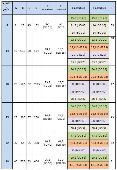
12 Dimensions of the device Page 11
13 Page 12
14 Parts list of the components of the SHP valve Page 13
15 REF 1 Valve body 2 Valve 3 Piston 4 Shaft 5 Shaft of valve 6 Cap 6.3 Bottom cap 7 Spring guide 8 Screw 9 Nut 10 Stainless-steel spring 11 Clips bracket 12 Clamp collar 13 Seal 14 Seal 15 Guiding band DESCRIPTION Page 14


16 3.2. Forced opening option View of the device This option concerns the models: SHP13, SHP20, SHP25, SHP32, SHP40 With lever for forced manual opening 3.3. Detection option The detection of escape opening option is relayed by an inductive detector fitted at the top of the valve. The detector is available in standard version or ATEX. View of the device This option concerns the models: SHP20, SHP25, SHP32, SHP40 With opening detector Page 15
17 3.4. ATEX option General ATEX version 2014/34/EC, areas 1 & 21, gas and dust. Under no circumstances, does the ATEX version of the product modify the specifications of the product and its components. This device is intended for use in surface installations (group II). The protection level of category 2 is suitable for normal use and frequently occurring disturbances for which malfunctions are normally taken into account. This equipment is for use in areas in which explosive atmospheres caused by mixtures of air and gas (G), vapours, mist or mixtures of air with dust (D), are likely to occur. The maximum surface temperature is the temperature of the fluid. Page 16
18 4 COMMISSIONING 4.1. Transport /Reception /Handling Upon receipt, check: That the package is in good condition That the device is delivered as ordered That the device has not been damaged If the product has the EC sign: And that the device is supplied with the EC compliance certificate, whose number must match the maker's plate fixed to the device If the device is damaged, it must not be fitted on the installation. Contact the manufacturer or equipment distributor Storage If the device is not fitted immediately after delivery, it should be stored carefully. It should be stored in its original packaging, in a covered area, with protection against dirt, rain, snow, insects and away from shock. The safe storage temperature is between 5 C and 40 C, with relative humidity of the air < 50%. If the device is stored at negative temperatures, the resistance of the materials to cold should be taken into account (e.g.: the seals). If storage is for longer than one year, the seals need to be replaced before commissioning Page 17

19 4.3. Installation General Before any utilisation of the equipment, the user must visually verify good condition: absence of corrosion, bits of packaging. If the fluid is harmful, inflammable, toxic, etc, fit the installation with discharge pipes going into a safe place. Also, you are advised to check the compatibility of these products with the seals and materials before using them. Before fitting this valve, you should check that the maximum PS of the equipment to protect, is higher or equal to the opening pressure of the valve. If the installation is outside in low temperature, you should take into account the risk of jamming of the valve by freezing and obstruction of the outlet by snow. To ensure drainage, the valve outlet pipes should be installed so that it has a slope up to the drain orifice situated at its lowest point. The outlet pipe must not be directed upwards immediately after the valve. It should be sufficiently sized for ease of access and capable of being inspected regularly. The fluids flowing out should be recovered (e.g.: by drains, systems of collectors or filters). The outlet orifice of the safety valve should be protected so that no mould or dirt can enter the valve. The outlet should be fitted between the horizontal and the vertical (but vertical always oriented downwards) to ensure good drainage. The fluid arrives by the base of the valve. The outlet is perpendicular to the inlet. Page 18

20 The safety valves should be fitted so that the dynamic vibrations of the installation cannot be transmitted to the safety valves. Fit the safety valves so that no static and thermic stress, of an inadmissible level, and coming from the upstream and downstream pipes can be transmitted to the valve. Also, take into account, when fitting, the forces of reaction which occur when opening and any dilatation due to the temperature during use. Systems preventing this dilatation should be fitted. Do not place blocking devices before the safety valve. SORTIE = Escape ENTREE = Equipment to be protected The workers The work described below should be carried out by qualified and experienced persons. The personnel must be fitted with gloves, helmet, and safety shoes. Fitting Place the entry of the valve on the clamp connector side, tank or pipes, inserting a suitable clamp seal and tighten the clamp collar. The connections should be made complying with the standards in force. Dismantling Drain the supply pressure from the equipment protected by the valve and unlock the clamp collar linking your installation to the valve. Page 19
21 Inlet pipe The inlet pipes must be as short as possible, to ensure cleaning the seating. Outlet pipe The pipes must not exert stress on the valve. Fit valve outlet pipes in a design favouring flow. The outlet pipes should be designed according to each condition of utilisation. There is a difference between systems of evacuation for steam or gas. The valve outlet pipes functioning on steam and gas should be designed to ensure a discharge from the valve safely, and no loss of charge at the outlet (at the rate of evacuation of the valve). Collecting the evacuation must not generate a back-pressure with escape at the rate planned. Page 20
22 5 USE 5.1. Functional checks During use, check the functioning of the safety valve every 6 months. To make sure that the valve is functional, you are advised to perform a flush. This flush can only be done if the service pressure is at least equal to 75% of the opening pressure. Without lifting system Create a brief and controlled overpressure, compared with the calibration of the valve. If this starts at the calibrated pressure (± statutory tolerance), the functioning is normal. With manual lifting system In order to verify the correct functioning of the valve, use the manual lifting system of the valve. Hold the handle and carry out a ¼ turn, around the shaft linking the system to the central shaft. If the rise occurs without any particular problem, this means that the O-ring providing the seal between the outside and the inside of the valve body, is in good condition and therefore that there is no problem. Verification of the good closing of the valve under-pressure. However, depending on the calibration of the valve, it can be more or less hard to lift the valve manually Adjustment The work described below should be carried out by qualified and experienced persons. This safety valve is governed by the directive of Device Under Pressure, and leadsealed. Because of this, adjustment is reserved for the manufacturer of the documented device. Contact SERVINOX or your distributor. Page 21
23 6 SERVICING AND MAINTENANCE 6.1. General The equipment requires maintenance to make sure it functions correctly. An inspection must be carried out at regular intervals. An initial inspection interval of 6 months is recommended. Certain properties of fluids (corrosive, aggressive, abrasive, residues, viscosity, etc) and certain environmental conditions (climate, pollution, etc) may require a reduction of these inspection intervals. SERVINOX supplies the spare parts for proper maintenance and the warranty on the equipment. We keep a store of sachets of wear parts (seals, etc) and we recommend that you keep a few sachets in stock for quick jobs. Inspections and servicing The minimum points to inspect are: INSPECTION Traces of corrosion? Deterioration of the seating and/or the valve of the valve? Pronounced wear of the seals? Presence of impurities in the valve and/or between the seating surfaces? Loosening of the assemblies Poor functioning of the valve DIAGNOSTIC POSITIVE? The valve must not be used REACTION Contact the manufacturer Contact the manufacturer Contact the manufacturer Remove the impurities and perform a test of functioning Tighten and perform a test of functioning Contact the manufacturer Page 22
24 Release with a viscous fluid: If there is a release with a viscous fluid, it is essential to clean the seal gaskets. To clean the exterior, the usual detergents can be used. Also, you are advised to check the compatibility of these products with the materials (metals, alloys, seals, etc) before using them. Check that the seal between the valve and the seating is not stuck by rapidly opening the valve using the various systems available. We advise you to enter all the maintenance and test operations carried out on the installation in a form of this type: Date Company Name of the worker Signature PREVENTIVE MAINTENANCE Operations Other, Comments CHECKS ON CORRECT FUNCTIONING AND GOOD CONDITION Operations Other, Comments Replacing wear parts The device requires the EC sign and a lead seal. For any internal inspection or changing of wear parts, contact Servinox to ensure the calibration of the valve after maintenance. In case of dismantling the valve, BE CAREFUL about the spring under pressure. Re-calibration The safety valve type SHP is a device governed by the Directive of the Device under pressure (PED), and subject to strict regulations. To ensure this compliance, Servinox does not allow the re-calibration of this safety valve by a third party. Re-calibration should be carried out by Servinox personnel. Page 23
25 7 DIAGNOSTIC AID The table below is a diagnostic aid and is intended to help you remedy simple functional problems. PROBLEM POSSIBLE CAUSE REMEDY The valve does not open at the intended opening pressure The rod is blocked by an outside obstacle Do not hinder the free movement of the rod, in outlet or inlet. The valve remains open The safety valve is not sealed An obstacle hinders the travel of the rod Impurities are present between the seating surfaces Do not limit the travel of the rod, in entry or outlet Perform a flush. If the valve is still not sealed after this flush, contact the manufacturer or equipment distributor. The connection is not sealed Poor tightness of the collars Check the tightness of the collars. The fluid escapes from the cap The valve seal is damaged If the valve is still not sealed, contact the manufacturer or equipment distributor. Contact the manufacturer or equipment distributor. The mobile parts are jammed Abrasive or corrosive fluids Carry out a maintenance of the valve after each opening in presence of viscous, abrasive, corrosive fluids. Ice, reduction of the flow The fluid solidifies because of too low ambient temperature Protect the safety valve and the pipes from cold Page 24

26 8 WARRANTY Unless otherwise stated in the proposal, the device is guaranteed 12 months as from the date of delivery. After an examination in our factory, the parts considered as defective will be replaced at our expense. All replacement of the device's components (wear parts, seal, etc) must be replaced by SERVINOX original parts The warranty does not cover damage due to: Poor fitting, inappropriate or abusive utilisation An accident or incorrect installation Modification of the equipment Leaks following the passage of impurities will not be taken into account Required maintenance not performed The warranty on our products covers the free repair of parts returned when proved that they have become unusable prematurely, following a manufacturing or material fault. We are not bound to any compensation or any other obligation of this kind. This equipment has been inspected before leaving the factory. This equipment has been certified as having been inspected and authorised for sale Page 25
27 Notes Page 26
28 34-36 Avenue Roger Hennequin Trappes cedex - France Tel.: + 33 (0) Fax: +33 (0) Home page: Page 27
HSV. Safety valve Ultra-clean. Instructions. Reference: HSV_NOT_EN Version C
 Safety valve Ultra-clean HSV Instructions Reference: Version C 34-36 Avenue Roger Hennequin 78197 Trappes cedex - France Tel.: + 33 (0)1 30 16 15 00 Fax: +33 (0)1 30 16 15 01 Home page: http://www.servinox.com
CAST IRON SAFETY VALVE TYPE 6301
 CHARACTERISTICS The 6301 safety valve is dedicated to protect the equipment from potential overpressure. This is an automatic device that closes when the pressure conditions are back to normal. It is a
G type DUCTED EXHAUST SAFETY VALVE 2871 AND 288X SERIES. Model/Ref:
 Model/Ref: 28713 www.lauridsenindustri.com CHARACTERISTICS The G type safety valves are dedicated to protect the equipment from potential overpressure. They are automatic and close when the pressure conditions
6301 TYPE CAST IRON SAFETY VALVES
 Pressure (bar) 6301 TYPE CAST IRON SAFETY VALVES FEATURES The 6301 type safety valve is a device designed to protect installations against possible overpressure. It operates automatically and closes when
Mounting and Operating Instructions EB 2558 EN. Self-operated Pressure Regulators. Type Pressure Build-up Regulator
 Self-operated Pressure Regulators Type 2357-31 Pressure Build-up Regulator with safety function and integrated excess pressure valve Type 2357-31 with non-return unit at port C Ports A and B with soldering
BT6HC Hygienic Sanitary Balanced Pressure Steam Trap for High Capacity and CIP/SIP Applications
 1800350/6 IM-P180-12 ST Issue 6 BT6HC Hygienic Sanitary Balanced Pressure Steam Trap for High Capacity and CIP/SIP Applications Installation and Maintenance Instructions 1. Safety information 2. General
TSS21 Sealed Thermostatic Steam Tracer Trap
 1255050/4 IM-P125-10 ST Issue 4 TSS21 Sealed Thermostatic Steam Tracer Trap Installation and Maintenance Instructions 1. Safety information 2. General product information 3. Installation 4. Commissioning
MODEL 200 KNIFE GATE VALVES INSTALLATION & MAINTENANCE MANUAL
 MODEL 200 KNIFE GATE VALVES INSTALLATION & MAINTENANCE MANUAL Index 1. List of components / General arrangement 2. Description 3. Handling 4. Installation 5. Actuators / Operation 6. Maintenance a. Changing
Safety Valves. Product Information. It s all at Albion
 Safety Valves Product Information It s all at Albion ART 642 Gunmetal Safety Valve Features Screwed BSP Parallel (ISO 228) Body Gunmetal Suitable for Gases, Liquids & Steam Fitted with Diaphragm to Protect
SRV66 Sanitary Pressure Reducing Valve
 1866350/4 IM-P186-09 CH Issue 4 SRV66 Sanitary Pressure Reducing Valve Installation and Maintenance Instructions 1. Safety information 2. General product information 3. Installation 4. Operation 5. Commissioning
PV4 and PV6 Piston Valves
 1181250/1 IM-P118-05 ST Issue 1 PV4 and PV6 Piston Valves Installation and Maintenance Instructions 1. Safety information 2. General product information 3. Installation 4. Commissioning 5. Operation 6.
TP1 and TP2 Temporary Cone Shaped Strainers
 1698051/2 IM-P169-07 ST Issue 2 TP1 and TP2 Temporary Cone Shaped Strainers Installation and Maintenance Instructions TP1 1. Safety information 2. General product information 3. Installation and commissioning
Operating Manual FSV, FSÖV, SSVF
 Contents 1. General Remarks... 1 1.1. Marking... 2 1.2. Tightness of the Quick-Closing Valve... 2 1.3. Medium... 2 1.4. Ambient and Medium Temperature... 3 1.5. Vibrations... 3 1.6. Pipe Tensions... 3
Type BBS-03, BBS-05, BBS-06, BBS-25
 Type BBS-03, BBS-05, BBS-06, BBS-25 Sterile connection elements Sterile Verbindungselemente Raccords union stériles Operating Instructions Bedienungsanleitung Manuel d utilisation 1. THE OPERATING INSTRUCTIONS
MST21 Stainless Steel Balanced Pressure Thermostatic Steam Trap
 1250650/6 IM-P125-07 ST Issue 6 MST21 Stainless Steel Balanced Pressure Thermostatic Steam Trap Installation and Maintenance Instructions 1. Safety information 2. General product information 3. Installation
Manual Actuated Boiler Blowdown Valves
 Manual Actuated Boiler Blowdown Valves Installation and Maintenance Instructions 1. Safety information 2. General product information 3. Installation 4. Operation 5. Maintenance 6. Spare parts p.1 1. Safety
Measurement accessories METPOINT OCV for the measurement in systems up to 40 bar
 EN - english Instructions for installation and operation Measurement accessories METPOINT OCV for the measurement in systems up to 40 bar Dear customer, Thank you for deciding in favour of the METPOINT
Dri-Line Mk3 Monnier Compressed Air Drain Trap
 5044050/2 IM-P504-24 CH Issue 2 Dri-Line Mk3 Monnier Compressed Air Drain Trap Installation and Maintenance Instructions 1. Safety information 2. General product information 3. Installation and Operation
Non-Return Valve SRK 22A
 Non-Return Valve SRK 22A Original Installation Instructions 819238-02 Contents Foreword... 3 Availability... 3 Formatting features in the document... 3 Safety... 3 Use for the intended purpose... 3 Basic
FV Flash Vessel Installation and Maintenance Instructions
 4041050/5 IM-P404-10 EMM Issue 5 FV Flash Vessel Installation and Maintenance Instructions 1. Safety information 2. Specific product safety information 3. Product information 4. Installation 5. Commissioning
CVS10 Sanitary Check Valves
 0299050/4 IM-P029-11 ST Issue 4 CVS10 Sanitary Check Valves Installation and Maintenance Instructions 1. Safety information CVS10 with soft seat 2. General product information 3. Operation 4. Installation
Inverted Bucket Steam Trap IB 16A-7
 Inverted Bucket Steam Trap IB 16A-7 Original Installation Instructions 819114-02 Contents Preface... 3 Availability... 3 Text layout... 3 Safety... 3 Usage for the intended purpose... 3 Basic safety notes...
Ball Float Steam Trap UNA 43 PN 16/CL 125/JIS 10K UNA 46 PN 40/CL 150/CL 300/JIS 10K/JIS 20K DN 80, 100, 150, 3", 4", 6"
 Data Sheet 819584-00 Issue Date: 01/17 Ball Float Steam Trap UNA 43 PN 16/C 125/JIS 10K UNA 46 PN 40/C 150/C 300/JIS 10K/JIS 20K DN 80, 100, 150, 3", 4", 6" UNA 43 hl, UNA 46 hl UNA 43 v, UNA 46 v with
Installation, Operating and Maintenance Instructions. V914 Cast Iron Flanged Swing Check Valve V914
 Installation, Operating and Maintenance Instructions V914 Cast Iron Flanged Swing Check Valve V914 THE PRESSURE EQUIPMENT DIRECTIVE 97/23/EC and CE MARKING The Pressure Equipment Regulations 1999 (SI 1999/2001)
776 Cryogenic Safety Valve
 776 Cryogenic Safety Valve INTRODUCTION 776 Cryogenic Safety Valve The effects of exceeding safe pressure levels in an unprotected pressure vessel or system, can have catastrophic effects on both plant
CARTRIDGE FILTERS TECHNICAL MANUAL MT 080. Installation, commissioning and maintenance instructions. 08/02 Edition
 CARTRIDGE FILTERS TECHNICAL MANUAL MT 080 Installation, commissioning and maintenance instructions 08/02 Edition 1 2 CONTENTS 1.0 PAGE INTRODUCTION 1.1 MAIN FEATURES 1.2 OPERATION 1.3 CLOSING OF HEAD WITH
Spiratec ST14, ST16 and ST17 Sensor Chambers and sensors
 0862050/1 IM-P086-18 MI Issue 1 Spiratec ST14, ST16 and ST17 Sensor Chambers and sensors Installation and Maintenance Instructions 1. Safety Information 2. General product information 3. Installation 4.
SAPAG. Safety valves, type 5700 Storage, Use, Operation and Maintenance Instructions. IMPORTANT NOTICE
 SAPAG IMPORTANT NOTICE Contents Important notice 1 0 Valve identification 2 1 Storage 2 2 Installation 2 3 Operation 2 4 Maintenance 3 4.1 Dismantling 3 4.2 Inspection 3 4.3 Repair 3 4.4 Assembly 4 4.5
Instruction manual. HLSD-2 Circular Access Tank Cover IM-TE91K041-EN1 ESE Date of issue: August 29, 2012
 Instruction manual HLSD-2 Circular Access Tank Cover ESE0226 Date of issue: August 29, 2012 First published: August 29, 2012 Contents Contents... 1 Introduction... 3 General description... Application...
KBV21i and KBV40i Key Operated Boiler Blowdown Valves Installation and Maintenance Instructions
 4059051/3 IM-P405-48 EMM Issue 3 KBV21i and KBV40i Key Operated Boiler Blowdown Valves Installation and Maintenance Instructions 1. Safety information 2. General product information 3. Installation 4.
3-PIECE BALL VALVE, 3600 PSI/ PN 248, WITH ISO DIRECT MOUNTING PAD 306M SERIES/ PED Category II
 3-PIECE BALL VALVE, 3600 PSI/ PN 248, WITH ISO DIRECT MOUNTING PAD 306M SERIES/ PED Category II 306M User Manual English Version Use for company in Europe who will place the product on the market, please
Steam Trap BK 15 (DN40, DN 50) Original Installation Instructions English
 Original Installation Instructions English") Steam Trap BK 15 (DN40, DN 50) EN English Original Installation Instructions 810682-03 1 Contents Page Important Notes Usage for the intended purpose... 4 Safety note... 4 Danger... 4 Attention... 4 Application
Steam Trap BK 15 (DN40, DN 50) EN English Original Installation Instructions 810682-03 1 Contents Page Important Notes Usage for the intended purpose... 4 Safety note... 4 Danger... 4 Attention... 4 Application
POP Safety Valve. POP Safety Valve INTRODUCTION DEFINITIONS
 POP Safety Valve POP Safety Valve INTRODUCTION The effects of exceeding safe pressure levels in an unprotected pressure vessel or system, can have catastrophic effects on both plant and personnel. Safety
Fig 12, Fig 14HP, Fig 16, Fig 16HP and Fig 16L Strainers
 16355/11 IM-S6-17 ST Issue 11 Fig 12, Fig 14HP, Fig 16, Fig 16HP and Fig 16L Strainers Installation and Maintenance Instructions 1. Safety information 2. General product information 3. Installation 4.
Product Manual B-Safety ClassicLine & PremiumLine Emergency Eyewash and Eye/Face Wash Equipment
 Product Manual B-Safety ClassicLine & PremiumLine Emergency Eyewash and Eye/Face Wash Equipment 1. Application Emergency eyewash and eye/face wash equipment are prescribed first aid installations for workplaces
DC5A. Cyclone Separator Trap for Air. Copyright 2015 by TLV Co., Ltd. All rights reserved ISO 9001/ ISO MA-03 (DC5A) 19 June 2015
 19 June 2015") 172-65205MA-03 (DC5A) 19 June 2015 ISO 9001/ ISO 14001 Manufacturer Kakogawa, Japan is approved by LRQA LTD. to ISO 9001/14001 Cyclone Separator Trap for Air DC5A Copyright 2015 by TLV Co., Ltd. All rights
172-65205MA-03 (DC5A) 19 June 2015 ISO 9001/ ISO 14001 Manufacturer Kakogawa, Japan is approved by LRQA LTD. to ISO 9001/14001 Cyclone Separator Trap for Air DC5A Copyright 2015 by TLV Co., Ltd. All rights
USER MANUAL. 1. Principle of operation. 2. Delivery condition. SPRING-LOADED SAFETY VALVES zarmak. Edition: 07/2016 Date: V (ex.
 ZETKAMA Sp. z o.o. ul. 3 Maja 12 PL 57-410 Ścinawka Średnia SPRING-LOADED SAFETY VALVES zarmak USER MANUAL 782V (ex. 782) Edition: 07/2016 Date: 01.07.2016 TABLE OF CONTENTS 1. Principle of operation 2.
AVM7 Stainless Steel Thermostatic Air Vent
 1231850/4 IM-P123-23 ST Issue 4 AVM7 Stainless Steel Thermostatic Air Vent Installation and Maintenance Instructions 1. Safety information 2. General product information 3. Installation 4. Commissioning
OFFICINE OROBICHE S.p.A. 1/9
 OFFICINE OROBICHE S.p.A. 1/9 INSTRUCTIONS MANUAL FOR LEVEL SWITCHES SERIES 7000 mod. 7250 AND 7400 Electric 1. INSTRUMENT DESCRIPTION Series 7000 level switches have been designed for external lateral
Operating Instructions in compliance with Pressure Equipment Directive 2014/68/EU. FAS Brass Check Valve RDL
 Operating Instructions in compliance with Pressure Equipment Directive 2014/68/EU FAS Brass Check Valve RDL Please read these operating instructions carefully to ensure a safe operation and keep the same
HYDROVEX TTT Membrane Flow Regulator
 HYDROVEX TTT Membrane Flow Regulator INSTALLATION, OPERATION AND MAINTENANCE MANUAL PROJECT EQUIPMENT LOCATION EQUIPMENT DESCRIPTION HYDROVEX TTT REFERENCE N OF THE SUPPLIER MODEL N SERIAL N DATE OF FABRICATION
Fig 1, Fig 12, Fig 13, Fig 14HP, Fig 16, Fig 16HP and Fig 16L Strainers
 16355/8 IM-S6-17 ST Issue 8 Fig 1, Fig 12, Fig 13, Fig 14HP, Fig 16, Fig 16HP and Fig 16L Strainers Installation and Maintenance Instructions 1. Safety information 2. General product information 3. Installation
Contents. 1. General information BROEN BALLOMAX Steel Ball Valves Approvals Quality Management...2
 Contents 1. General information...2 1.1 BROEN BALLOMAX Steel Ball Valves...2 1.2 Approvals...2 1.3 Quality Management...2 2. Preoperational Instructions and Precautions...2 3. Plates...3 4. Transport and
KBV21i and KBV40i Air Actuated Boiler Blowdown Valves
 4059051/1 IM-P405-48 AB Issue 1 KBV21i and KBV40i Air Actuated Boiler Blowdown Valves Installation and Maintenance Instructions 1. Safety information 2. General product information 3. Installation 4. Commissioning
Assembly and Installation Procedures
 Assembly and Installation Procedures for Pall Supracap 100 Capsules 1. Introduction The following procedures must be followed for the installation of Pall Supracap 100 Capsules. The instructions contained
6-5 Maintenance Manual
 Non Return Valve 6-5 Maintenance Manual Contents 1. PRODUCT DESCRIPTION... 1 1.1 How it works... 1 1.2 Overall dimensions... 3 1.3 Technical datasheet... 4 1.3.1 Push flow situation... 4 1.3.2 Pull flow
Neotecha SAPRO - Aseptic sampling valve SV Installation, operation and maintenance instructions
 Before installation these instructions must be fully read and understood 2 Safety Please read these instructions carefully. 2.1 General danger potential Not paying attention to this instruction Incautious
Siphon vessel / Priming aid
 Manufacturer: sera GmbH sera-straße 1 34376 Immenhausen Germany Tel.: +49 5673 999-00 Fax: +49 5673 999-01 info@sera-web.com Keep the operating manual for future use! Record the exact type and serial number
UIB30 and UIB30H Sealed Inverted Bucket Steam Traps for use with Pipeline Connectors
 1130050/4 IM-P113-02 ST Issue 4 UIB30 and UIB30H Sealed Inverted Bucket Steam Traps for use with Pipeline Connectors Installation and Maintenance Instructions 1. Safety information 2. General product information
RS(H)10,15 USER MANUAL. Read the complete manual before installing and using the regulator.
10,15 USER MANUAL. Read the complete manual before installing and using the regulator.") RS(H)10,15 USER MANUAL Read the complete manual before installing and using the regulator. WARNING INCORRECT OR IMPROPER USE OF THIS PRODUCT CAN CAUSE SERIOUS PERSONAL INJURY AND PROPERTY DAMAGE. Due to
RS(H)10,15 USER MANUAL Read the complete manual before installing and using the regulator. WARNING INCORRECT OR IMPROPER USE OF THIS PRODUCT CAN CAUSE SERIOUS PERSONAL INJURY AND PROPERTY DAMAGE. Due to
HM and HM34 Inverted Bucket Steam Traps Installation and Maintenance Instructions
 0670350/4 IM-S03-11 ST Issue 4 HM and HM34 Inverted Bucket Steam Traps Installation and Maintenance Instructions 1. Safety information 2. General product information HM Series 3. Installation 4. Commissioning
TA10A and TA10P Steam Tracing Temperature Control Valves Installation and Maintenance Instructions
 3500032/2 IM-P350-02 CH Issue 2 TA10A and TA10P Steam Tracing Temperature Control Valves Installation and Maintenance Instructions 1. Safety information 2. General product information 3. Installation 4.
DCV1, DCV3 and DCV3LT Disc Check Valves Installation and Maintenance Instructions
 1340050/7 IM-P134-07 CMGT Issue 7 DCV1, DCV3 and DCV3LT Disc Check Valves Installation and Maintenance Instructions 1. Safety information 2. General product information 3. Installation 4. Commissioning
OPERATING MANUAL. Contents. Bottom outlet ball valve Type ecoline
 OPERATING MANUAL Bottom outlet ball valve Type ecoline Contents 1 General Information 2 Safety 3 Packing, Handling, Storing 4 Product description 5 Preparation, Assembly 6 Commissioning 7 Handling 8 Attendance
Instruction manual. for. high purity gas pigtails 200 bar / 300 bar
 Instruction manual for high purity gas pigtails 200 bar / 300 bar Contents Contents... 2 1. Preface... 3 1.1 Overview... 3 1.2 General... 3 1.3 Intended use... 4 1.4 Personnel requirements... 4 2. For
APT14, APT14HC and APT14SHC Spares 2
 6120251/7 IM-P612-06 ST Issue 7 APT14, APT14HC and APT14SHC Spares 2 Installation and Maintenance Instructions 1. Safety information 2. Replacement of trap and outlet check valve mechanism 3. Replacement
756 Safety Relief Valves
 756 S a fe t y R e l i e f Va l ve s INTRODUCTION 756 Safety Relief Valves The effects of exceeding safe pressure levels in an unprotected pressure vessel or system, can have catastrophic effects on both
Declaration of Conformity as per Directive 97/23/EC
 Declaration of Conformity as per Directive 97/23/EC The manufacturer declares that:, 47906 Kempen, Germany Multi-way diverting valves Series 29a and Series 29b, with packing with lever 1. The valves are
Target disk flowmeter Series DP. Instructions manual DP65 DP500. R-MI-DP Rev.: 4 English version
 Target disk flowmeter Series DP Instructions manual DP65 DP500 R-MI-DP Rev.: 4 English version PREFACE Thank you for choosing the flowmeter series DP from Tecfluid S.A. This instruction manual allows the
IFTGS14 Ball Float Steam Trap ½" and ¾" with Integral Spiratec Sensor
 6150350/3 IM-P615-12 ST Issue 3 IFTGS14 Ball Float Steam Trap ½" and ¾" with Integral Spiratec Sensor Installation and Maintenance Instructions 1. Safety information 2. General product information 3. Installation
30T A/Manual Hydraulic Shop Press
 30T A/Manual Hydraulic Shop Press Operation Manual 1 1. Important Information 1.1 Safety Information 1.1.1 Hazard Symbols Used in the Manuals This manual includes the hazard symbols defined below when
VALFONTA INSTRUCTIONS: OPERATION AND INSTALLATION PRESSURE REDUCING VALVE MODEL M2
 INSTRUCTIONS: OPERATION AND INSTALLATION PRESSURE REDUCING VALVE MODEL M2 Pressure Reducing Valve M2 - Operation and Installation - 1 - M2-13E-ENG FEBRUARY 2017 ÍNDICE PÁGINA 1 IDENTIFICATION PLATE LEGEND
Dri-Line Mk2 Spirax-Monnier Compressed Air Drain Trap
 0509950/2 IM-P050-21 CH Issue 2 Dri-Line Mk2 Spirax-Monnier Compressed Air Drain Trap Installation and Maintenance Instructions 1. Safety information 2. General product information 3. Installation and
Un-Pressurized Orefice Fittings FIO EZ. Parts List and Operation Instructions TECHNICAL MANUAL. Dn 2-6 Class Lbs
 Un-Pressurized Orefice Fittings FIO EZ Parts List and Operation Instructions TECHNICAL MANUAL Dn 2-6 Class 150-600 Lbs US US 2 FIO EZ - MT 108-US - 05-2016 FIO EZ Important Instructions US Pietro Fiorentini
FTGS14 Ball Float Steam Trap DN15 (½") to DN25 (1")
 to DN25 (1)") 1458050/5 IM-P145-12 ST Issue 5 FTGS14 Ball Float Steam Trap DN15 (½") to DN25 (1") Installation and Maintenance Instructions 1. Safety information 2. General product information 3. Installation 4. Commissioning
1458050/5 IM-P145-12 ST Issue 5 FTGS14 Ball Float Steam Trap DN15 (½") to DN25 (1") Installation and Maintenance Instructions 1. Safety information 2. General product information 3. Installation 4. Commissioning
DF1 and DF2 Diffusers
 1550650/4 IM-P155-07 ST Issue 4 and Diffusers Installation and Maintenance Instructions 1. Safety information 2. General product information 3. Installation 4. Commissioning 5. Operation 6. Maintenance
Mounting and Operating Instructions EB 3007 EN. Self-operated Pressure Regulators. Differential Pressure Regulators (opening) Type Type 42-25
 Type Type 42-25") Self-operated Pressure Regulators Differential Pressure Regulators (opening) Type 42-20 Type 42-25 Type 42-20 Differential Pressure Regulator Type 42-25 Differential Pressure Regulator Mounting and Operating
Self-operated Pressure Regulators Differential Pressure Regulators (opening) Type 42-20 Type 42-25 Type 42-20 Differential Pressure Regulator Type 42-25 Differential Pressure Regulator Mounting and Operating
BTM7, BTS7 and BTS7.1 Stainless Steel Thermostatic Clean Steam Traps
 1801050/10 IM-P180-05 ST Issue 10 BTM7, BTS7 and BTS7.1 Stainless Steel Thermostatic Clean Steam Traps Installation and Maintenance Instructions 1. Safety information 2. General product information 3.
THE BP-301 SERIES. Operating and Service Manual. Series includes all variants of BP-301 (LF 0.1Cv / MF 0.5Cv)
") THE BP-301 SERIES Operating and Service Manual Series includes all variants of BP-301 (LF 0.1Cv / MF 0.5Cv) Issue B October 2015 1 TABLE OF CONTENTS 1. Description... 3 2. Installation... 3 3. Operation...
THE BP-301 SERIES Operating and Service Manual Series includes all variants of BP-301 (LF 0.1Cv / MF 0.5Cv) Issue B October 2015 1 TABLE OF CONTENTS 1. Description... 3 2. Installation... 3 3. Operation...
TEST BENCH SAFETY VALVES ¼ - 5 DN10 DN125
 TEST BENCH SAFETY VALVES ¼ - 5 DN10 DN125 Model: VC-40-VYC Table of contents 1. - Installing the test bench 1.1.1- Connecting the compressed air / nitrogen source 1.1.2- Maximum test pressure according
Pressure Equipment Directive (PED) 97/23/EC Page 033 of 124
 97/23/EC Page 033 of 124") Pressure Equipment Directive (PED) 97/23/EC Page 033 of 124 13.7 Pressure Equipment Directive (PED) 97/23/EC 1 The Pressure Equipment Directive (PED) 97/23/EC applies to the design, manufacturing and conformity
Pressure Equipment Directive (PED) 97/23/EC Page 033 of 124 13.7 Pressure Equipment Directive (PED) 97/23/EC 1 The Pressure Equipment Directive (PED) 97/23/EC applies to the design, manufacturing and conformity
TECHNICAL DATA. Q = C v P S
 Page 1 of 13 1. DESCRIPTION The Viking 6 Model G-6000 Dry Valve Riser Assembly consists of a small profile, light weight, pilot operated valve that is used to separate the water supply from the dry sprinkler
AE14 Automatic Air Vents for Liquid Systems Installation and Maintenance Instructions
 1490050/7 IM-P149-06 CMGT Issue 7 AE14 Automatic Air Vents for Liquid Systems Installation and Maintenance Instructions 1. General safety information 2. General product information 3. Installation 4. Commissioning
Latvin Luxury Shower Panel. Telephone Product Specification. ~ Minimum Working Pressure 1.0 bar ~ Maximum Working Pressure 3.
 Product Specification ~ Minimum Working Pressure 1.0 bar ~ Maximum Working Pressure 3.0 bar Latvin Luxury Shower Panel ~ Fixing Centres 150mm +/- 10mm ~ Outlet size 1/2" Bottom Outlet Always maintain a
ML3M Monnier Miniature Compressed Air Lubricator
 5041050/3 IM-P504-04 CH Issue 3 ML3M Monnier Miniature Compressed Air Lubricator Installation and Maintenance Instructions 1. Safety information 2. General product information 3. Installation and commissioning
Installation & Operation Manual Proven Quality since 1892
 Content 1. ERIKS operating companies 2. Product description 3. Requirements for maintenance staff 4. Transport and storage 5. Function 6. Application 7. Installation 8. Maintenance 9. Service and repair
Operating instruction
 Operating instruction MV, XV, HG, HP, RKO, D2G, TV, BV, WB & SLV 1 Introduction 2 2 Stafsjö s knife gate valves 2 3 Technical information 2 3.1 Pressure test 2 3.2 Labelling 2 4 Storage 3 5 Transportation
S1, S2, S3, S5, S6, S7, S8, S12 and S13 Separators Installation and Maintenance Instructions
 PREVIOUS REFERENCE NO. IMP02355 0231150/13 IMF0501ENISS2 CMGT S1, S2, S3, S5, S6, S7, S8, S12 and S13 Separators Installation and Maintenance Instructions 1. Safety information 2. General product information
THE MF-400 SERIES. Operating and Service Manual. Series includes all variants of MF-400/401
 THE MF-400 SERIES Operating and Service Manual Series includes all variants of MF-400/401 Issue A October 2013 1 TABLE OF CONTENTS 1. Description... 3 2. Installation... 3 3. Operation... 4 4. Special
USM21 Sealed Bimetallic Steam Trap for use with Pipeline Connectors Installation and Maintenance Instructions
 6250250/1 IM-P625-03 ST Issue 1 USM21 Sealed Bimetallic Steam Trap for use with Pipeline Connectors Installation and Maintenance Instructions 1. General safety information 2. General product information
Automatic Non-freeze Valve NF6
 172-65134MA-03 (NF6) 30 March 2015 ISO 9001/ ISO 14001 Manufacturer Kakogawa, Japan is approved by LRQA LTD. to ISO 9001/14001 Automatic Non-freeze Valve NF6 Copyright 2015 by TLV CO., LTD. All rights
Atmospheric relief valve type 1100 Installation and maintenance instructions
 SAPAG 1. Description Sapag atmospheric relief valves type 1100 have been selected for installation because of their performance features, reliability and ease of maintenance. They are designed to protect
FLANGED TWO-PIECE BALL VALVES
 INTRODUCTION This instruction manual includes installation, operation, and maintenance information for FNW flanged split-body ball valves. This manual addresses lever operated ball valves only. Please
PRS(TC)4,8 USER MANUAL. Read the complete manual before installing and using the regulator.
4,8 USER MANUAL. Read the complete manual before installing and using the regulator.") PRS(TC)4,8 USER MANUAL Read the complete manual before installing and using the regulator. WARNING INCORRECT OR IMPROPER USE OF THIS PRODUCT CAN CAUSE SERIOUS PERSONAL INJURY AND PROPERTY DAMAGE. Due to
PRS(TC)4,8 USER MANUAL Read the complete manual before installing and using the regulator. WARNING INCORRECT OR IMPROPER USE OF THIS PRODUCT CAN CAUSE SERIOUS PERSONAL INJURY AND PROPERTY DAMAGE. Due to
FLANGED MULTI-PORT BALL VALVES
 INTRODUCTION This instruction manual includes installation, operation and maintenance information for flanged multi-port ball valves. This manual addresses lever operated ball valves only. Please refer
VALFONTA INSTRUCTIONS: OPERATION AND INSTALLATION PRESSURE REDUCING VALVE MODEL PRV44
 INSTRUCTIONS: OPERATION AND INSTALLATION PRESSURE REDUCING VALVE MODEL PRV44 Pressure Reducing Valve PRV44 - Operation and Installation - 1 - manual PRV44-16-ENG JULY 2016 INDEX PAGE 1 IDENTIFICATION PLATE
OPERATING MANUAL CHEMTRAC 840M MANUAL RETRACTABLE PROCESS HOLDER
 OPERATING MANUAL CHEMTRAC 840M MANUAL RETRACTABLE PROCESS HOLDER Table of contents 1 Security and safety measures... 5 1.1 General safety instructions... 5 1.2 Intended use... 5 1.3 Danger zones and residual
Operating and maintenance manual Filter and reducing station Series / 1.0
 Operating and maintenance manual Filter and reducing station Series 961 04.2017 / 1.0 Original instructions ARCA Regler GmbH. All rights reserved. Cover picture background: Freepik.com ARCA Regler GmbH
Flowmeter. Original operating manual DFM
 Flowmeter Original operating manual Series DFM 165 350 Version BA-2016.08.09 EN Print-No. 300 458 TR MA DE Rev002 ASV Stübbe GmbH & Co. KG Hollwieser Straße 5 32602 Vlotho Germany Phone: +49 (0) 5733-799-0
OPERATING INSTRUCTIONS MANUAL FOR QACV PNEUMATIC DOSING PUMP
 This operating instructions contains safety information that if ignored can endanger life or result in serious injury. They are indicated by this icon. Use of this pump with radioactive chemicals is forbidden!
Magnetic level switch type MR783 Instruction Manual
 Magnetic level switch Magnetic level switch type MR783 1. DESCRIPTION page 3 1.1 Operation page 3 1.2 Application page 3 1.3 Description page 3 2. SPECIFICATIONS page 3 2.1 Service Conditions page 4 2.2
Related Products: Auto Drain Valve. Model/Specifications. Model
 Related Products: Auto Drain Valve /600 Drainage is automatically discharged in a reliable manner, without requiring human operators. Highly resistant to dust and corrosion, operates reliably, and a bowl
Spilt body Flange ball valve. TC-205MFF-PN1640 User Manual English Version. Document No: TC-205MFF-PN1640.Ur-manual. Date: 2007/04/2617. Version: 1.
 Spilt body Flange ball valve TC-205MFF-PN1640 Series PED Category I,II TC-205MFF-PN1640 User Manual English Version Use for company in Europe who will place the product on the market, please amend which
Neotecha SAPRO - Tank Valve Type ST for aseptic sampling with bottles Installation, Operation and Maintenance Instruction
 7 Before installation these instructions must be fully read and understood 1.4 Illegal technical changes It is illegal to do mechanical changes of the design of the Sapro tank valve, or to use parts of
TECHNICAL DATA 3 MODEL G-3000 DRY VALVE RISER ASSEMBLY
 Page 1 of 13 1. DESCRIPTION The Viking 3 Model G-3000 Dry Valve Riser Assembly is equipped with a small profile, light weight, pilot operated valve that is used to separate the water supply from the dry
INSTRUCTIONS AND MAINTENANCE MANUAL SERIES: K
 INSTRUCTIONS AND MAINTENANCE MANUAL 05/09/2014 SERIES: K cmo@cmo.es http://www.cmo.es Page 1 ASSEMBLY DESCRIPTION Machinery Directive: DIR 2006/42/EC (MACHINERY) Pressure Equipment Directive: DIR 97/23/EC
1. Preface Important Safety Notes Brief Product Information Product Working Principle Installation Guidelines...
 Table of Contents 1. Preface...1 2. Important Safety Notes...1 3. Brief Product Information...3 4. Product Working Principle...5 5. Installation Guidelines...6 6. Startup and Commissioning...8 7. Maintenance
Type Operating Instructions. 2/2-way solenoid valve 2/2-Wege Magnetventil Electrovanne 2/2 voies.
 2/2-way solenoid valve 2/2-Wege Magnetventil Electrovanne 2/2 voies We reserve the right to make technical changes without notice. Technische Änderungen vorbehalten. Sous réserve de modifications techniques.
The flow direction must be observed during installation. It can be recognized by the following features: Flow direction. Gasket
 6.2 Installation of the Safety Valve The correct installation within a plant is essential for the proper operation of a safety valve. Installation in this sense is e.g. - the choice of the gaskets - the
Declaration of Conformity as per Directive 97/23/EC
 Declaration of Conformity as per Directive 97/23/EC The manufacturer declares that:, 47906 Kempen, Germany Continuous, inline sampling valves Series 27f, with packing Operate with either; Star lever, or