DASSAULT FALCON 900EX EASY SYSTEMS SUMMARY
|
|
|
- Dwight Berry
- 6 years ago
- Views:
Transcription

1 DASSAULT FALCON 900EX EASY SYSTEMS SUMMARY Air Conditioning & Pressurization The material contained on this site is to be used for training purposes only. Do not use it for flight! Please note that this document is not affiliated in any way with any aircraft manufacturer.
2 AIR CONDITIONING & PRESSURIZATION INTRODUCTION In order to maintain a comfortable area inside the cabin, the F900EX EASy is equipped with an air conditioning and pressurization system. The air conditioning system regulates the flow and temperature of air into the cabin and cockpit areas for conditioning purpose. The pressurization system regulates the cabin pressure, by the air flow discharged outside of the cabin, it depends on: - airplane altitude, - airplane vertical speed, - the maximum differential pressure supported by the system. Both systems have an automatic mode and a manual mode, allowing the pilot to control directly the valves. They use hot air supplied by the engines and/or the APU. In case of failure (overpressure, negative pressure, maximum altitude), protections ensure that limitations are observed. Page 1
3 Page 2
4 SOURCES The air conditioning system uses air supplied by: - engine No 1, - engine No 2, - engine No 3, - APU. For more information, refer to CODDE 1 / Chapter 02 / ATA 36. The conditioned air is a mixture of: - hot bleed air directly supplied by engines HP and LP ports, or the APU, - cold air (hot bleed air cooled through the Environmental Control Unit (ECU)), - recycled cabin air. The air conditioning heat exchanger is ventilated: - in-flight, with external air supplied through a ram air inlet located on the No 1 engine pylon leading edge, - on ground or in-flight at low speed, with additional air supplied through an air inlet located on the lower part of the fuselage. AIR CONDITIONING PRESSURIZATION Engine No 1, 2 and 3 and/or APU bleed air Recycled cabin air Conditioned air Ram air (for heat exchanger ventilation) Page 3
5 EQUIPMENT LOCATION Page 4
6 DESCRIPTION INTRODUCTION The air conditioning system provides the pressurized areas with air at mild temperature. It consists of: - Environmental Control Unit (ECU), - distribution system. The system is supplied with hot air coming from the common duct of the bleed air system. The hot air enters the conditioning system via a cockpit conditioning electric valve or a cabin conditioning electric valve through a flow limiter and an ozone catalyzer. Positions of the two valves are controlled by the CABIN and CKPT pushbuttons located on the BLEED AIR overhead panel (for more information, refer to ATA 36). Downstream from the conditioning valves, a variable amount of hot air is directed to the Environmental Control Unit (ECU) cooling system, through cockpit and cabin temperature control dual electric valves. These valves are controlled in automatic or manual mode from the AIR CONDITIONING overhead panel. Cold air generated by the ECU is mixed with hot bleed air inside the cockpit and cabin ducts to obtain the desired air temperature. Cold air from the ECU is also provided to the gaspers and used for cockpit avionics cooling. Page 5
![Falcon 900EX EASY [Air Conditioning & Pressurization Summary]](/docs-images/74/69953608/images/7-0.jpg "ENVIRONMENTAL CONTROL UNIT (ECU) The purpose of the")


, - a turbine")
7 Falcon 900EX EASY [Air Conditioning & Pressurization Summary] ENVIRONMENTAL CONTROL UNIT (ECU) The purpose of the environmental control unit is to generate the cold air required by the cockpit and passenger cabin air conditioning systems, and the cold air system. The ECU is mainly composed of: - a dual heat exchanger, - a turbofan, - a by-pass electric valve, - a turbocooler, - two water separators (High Pressure and Low Pressure), - a turbine anti-icing electric valve, - an overheat detection system. Page 6
8 Falcon 900EX EASY [Air Conditioning & Pressurization Summary] Dual Heat exchanger The hot bleed air is pre-cooled inside the primary part of the exchanger. The air flow is then routed to the turbo-cooler compressor or through the turbofan depending on the bypass electric valve position. At the turbo-cooler compressor outlet, the air is cooled inside the main heat exchanger prior to entering the turbine section of the turbo-cooler. Turbofan The purpose of the turbofan is to accelerate the cooling outside airflow through the exchangers when airplane True Air Speed is lower than 300 kt. It consists of a fan and turbine mounted on opposite ends of a common shaft. When airplane speed becomes high enough, the turbine/fan assembly is prevented from rotating by a braking system composed of a disk brake controlled via an electric valve. The electric and the by-pass electric valves are automatically controlled according to: - airplane speed, - slats position, - landing gear position. Turbo-cooler The turbo-cooler is a single stage compressor and turbine. The turbo-cooler operates in conjunction with the heat exchangers and the water separator to produce cooled and dry air for the conditioning system. Page 7
9 Water-separators The water separator separates and collects the water droplets formed in the condenser. The water is then routed to the atomizer. Two atomizers discharge it, as a fine mist, into the cooling airflow of the main heat exchanger and contribute to the cooling process. Anti-icing system An anti-icing system is used to prevent ice in the turbo-cooler turbine thanks to hot air picked off at the primary heat exchanger inlet and introduced into the turbo-cooler turbine casing. Hot air admission is controlled through an automatic valve to maintain the inlet temperature turbine above + 3 C (37 F). Optional emergency anti-icing valve For airplane fitted with the optional M2521 modification, when the standard turbine antiicing valve is detected jammed open, the optional electric turbine anti-icing valve can be closed by activating the CLOSE soft key in the ECS synoptic (soft key available only when the option is installed). Overheat detection system The overheat detection system consists of a sensor located in the turbo-cooler compressor outlet duct. The ECU OVHT CAS message is displayed when the bypass electric valve is not closed and: - the duct temperature reaches or exceeds 230 C (446 F), or - the nose gear is down and turbofan brake operating. Page 8
.")
10 DISTRIBUTION The distribution system is divided into: - the cockpit conditioned air system, - the cabin conditioned air system (for passengers, equipment and hold). Page 9


11 AIR CONDITIONING HOT SYSTEM SCHEMATIC Temperature control valves The temperature control valves of the cabin and cockpit systems are identical but differ in operation. Each assembly consists of two butterfly valves, mechanically linked and operated in an opposing direction by a single motor. The motor receives inputs from either the automatic or manual temperature control system of the associated controller. Even if the cabin temperature control valve is in full hot position, the cold butterfly valve is not fully closed, allowing a volume of air to pass through the ECU. Each temperature control valve is supplied through the associated air conditioning valve. The air mass through each valve is directed into two ducts: - one duct supplies hot air flow to the associated jet pumps in the cabin and cockpit distribution system, - the other duct supplies an air mass to a common duct, which directs it through the cold air unit. Page 10


12 Falcon 900EX EASY [Air Conditioning & Pressurization Summary] Cabin ducts The cabin air conditioning ducts are routed within the lower side of the left and right hand cabin side consoles. Passenger and crew conditioned air ducts may be manually interconnected to allow either the cabin or the cockpit distribution system to supply both ducting systems. The manual interconnection valve is located on the lower right-hand side of the cabin area. CONDITIONING CONTROL LEVER (APPLICABLE TO AIRPLANE < 141) CONDITIONING CONTROL LEVER (APPLICABLE TO AIRPLANE 141) Page 11
13 Cockpit ducts The cockpit conditioning ducts are routed along the right side of the fuselage and supply conditioned air to the entrance area, the cockpit, the windshields and the foot warmers. Each pilot selects the direction of the air supply (to the windshield for defogging or to the foot warmer) with a control lever on the instrument console. Two-way ducts The two-way ducts (one for the cockpit and one for the cabin) are routed along the top of the cabin. They have two functions: - distribute cold air to the upper part of the cabin / cockpit when the air conditioning requires a temperature drop, - recycle air from the cabin / cockpit and mix it with conditioned air when conditioning requires a temperature rise. Gaspers ducts The duct system providing cold air to the gaspers is a three-branch system: - one branch supplies the crew air gaspers, the air cooling tube for the MDU / PDU and for airplane fitted with M3374, the glareshield. An additional control lever located on the left side console enables to control cold air flow to the glareshield (M3374), - the other two branches supply the gaspers of the left and right side of the cabin. Cold air is directly supplied from the turbo-cooler through the low pressure water separator. Air supplied to the gaspers and for MDU / PDU cooling is maintained at a constant pressure through a pressure regulating valve. MDU / PDU cooling Cooling of the components of the instrument panel is achieved by airflow coming from the crew gasper system. Floor heating Air is distributed between the floor panels and the fuel tanks by a manifold supplied with cabin conditioning air. In addition to that air, cockpit air is evacuated underneath the floor panels to help floor heating. Baggage compartment conditioning The baggage compartment is conditioned by extracted air, from the cockpit hot air line, through the heat electric valve. It is pressurized at the same differential pressure as the cabin area through the isolation valve. This valve allows the baggage compartment to be isolated from the pressurization system. Page 12
14 When the baggage compartment isolation is commanded and the isolation valve is closed, the amber BAG ISOL CAS message is displayed. Nose cone ventilation An electric blower ventilates the nose cone during ground operations and in-flight at low altitude (differential pressure < 0.7 psi). In flight, ventilation is also provided by the cabin conditioned air through a calibrated orifice. The air is evacuated through the nose gear well. The NOSE CONE OVHT temperature exceeds 70 C (158 F). Air evacuation CAS message appears if the nose cone ambient Cabin air is evacuated via the lavatory through the outflow valves. Cockpit air is evacuated from the rear of the pilot and copilot consoles, circulates underneath the cabin floor and is directed to the outflow valves. AIR EVACUATION CIRCUITS Sensors Temperature sensors located in the cabin and cockpit ducts provide air temperature inputs to the corresponding controller. Temperature switches are activated when air duct temperature is over 95 C (203 F) The amber COND OVHT XX CAS message is then displayed and the lines on the ECS synoptic corresponding to the overheated duct are displayed in amber. Page 13

.")
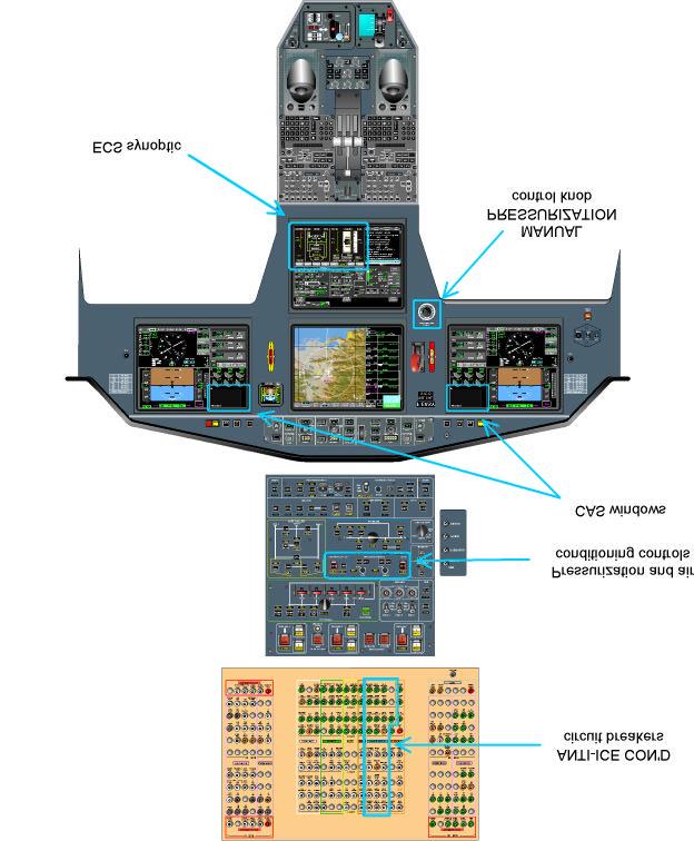
15 CONTROL AND INDICATION CONTROL AIR CONDITIONING OVERHEAD PANEL ECS SYNOPTIC NOTE The REMOTE soft key is active only when the option is installed In automatic mode, by selecting the REMOTE soft key, the cabin temperature can be controlled directly from a rotactor located in the cabin (VIP seat). Page 14


16 Synthetic table CONTROL FUNCTION TO ACTIVATE TO DEACTIVATE SYNOPTIC Automatic mode: the PAX / CREW rotactor is used to select cabin / cockpit temperature Manual mode: the PAX / CREW rotactor must be at full counter clockwise position. MAN is displayed on the left side and the COLD / HOT pushbuttons are used to control the cabin/cockpit temperature Auto mode Manual mode PAX Auto CREW Auto PAX Manual CREW Manual BAG BAG pushbutton is located in the BLEED AIR overhead panel: - pressed once, closes the baggage compartment heat valve Normal BLD synoptic - pressed twice, closes the isolation valve between baggage compartment and cabin Heat valve closed BAG HEAT status light pushbutton The synoptic is displayed in the BLD synoptic page. For more information, refer to CODDE 1 / Chapter 02 / ATA 36 Baggage comp t isolated BLD synoptic ISOL BAG HEAT BLD synoptic Page 15

17 INDICATION Air conditioning indications and system status are displayed on the ECS synoptic. Command indications include cabin temperature remote mode selection. The system status items include operating status, cockpit and cabin temperature regulation valve positions and cabin temperature. The cockpit and cabin temperature control valve positions are indicated by two vertical bar graphs located at the bottom of the air conditioning schematic of the ECS synoptic. The bar graphs and associated color present the temperature control valve actual positions. A full brown bar graph indicates a full hot valve position and a full blue indicates a full cold position. ECS SYNOPTIC Page 16
18 Cold air unit and air flow lines indication Cabin and Cockpit temperature control valve when temperatures are invalid T cabin duct air > 95 C COND OVHT PAX CAS message T cockpit duct air > 95 C COND OVHT CREW CAS message T compressor ECU outlet air > 230 C or nose gear down and turbofan by-pass valve not closed ECU OVHT CAS message NOTE The remote control is authorized by selecting the REMOTE soft key on the ECS synoptic. The remote control is authorized in conditioning AUTO mode only. Upon the manual mode selection, the REMOTE control is automatically de-selected and the REMOTE selection is impossible. Page 17

19 Cabin temperature indication Cabin temperature indication is presented on the right of the PAX label. The indication is based on the air cabin temperature measurement. The temperature spacing is 1. The readout ranges from 0 to 40 C. When the signal is invalid, two amber dashes are displayed in place of temperature indication. CREW and PAX indications during emergency pressurization The activation of the EMERG pressurization pushbutton simultaneously: - closes the CABIN conditioning valve, - drives the CKPT temperature control valve into full hot position, Airflow admission to the ECU is shut off. Conditioning is therefore only achieved by mixing ambient cabin air with hot bleed air. Temperature control at high altitude may not present a problem. But, at lower altitude, cabin and cockpit ambient temperature will naturally increase. In this case, temperature may be manually controlled by using the COLD CREW pushbutton that commands hot bleed airflow reduction but consequently affects cabin pressurization. Page 18

20 SYSTEM PROTECTION INTRODUCTION Electrical circuit protection is provided by conventional trip-free circuit breakers located above the overhead panel. CIRCUIT BREAKERS AIR CONDITIONING CIRCUIT BREAKERS Page 19
21 NORMAL OPERATION In the following, typical situation has been selected to help the crew to understand the symbols provided in the various panels and displays. ECS SYNOPTIC Page 20

22 ABNORMAL OPERATION INTRODUCTION In the following, abnormal operations have been selected to help the crew to understand the symbols provided in the various panels and displays. AIR CONDITIONING WITH CABIN OVERHEAT Abnormal status ECS SYNOPTIC CONTEXT Cabin conditioning system overheat RESULT COND OVHT PAX + light on CAS message CABIN air flow line in amber Page 21
23 After procedure complete AIR CONDITIONING OVERHEAD PANEL ECS SYNOPTIC ACTION RESULT CABIN air conditioning in manual mode PAX rotactor fully counter clockwise MAN status light in amber REMOTE status de-selected COLD PAX pushbutton pressed and maintained CABIN temperature valve position 100 % blue CABIN air flow line in green Page 22
24 AIR CONDITIONING WITH ECU OVERHEAT Abnormal status ECS SYNOPTIC CONTEXT ECU (COLD AIR UNIT) overheat ECU OVHT + light on RESULT CAS message COLD AIR UNIT air flow lines in amber Page 23

25 After procedure complete AIR CONDITIONING OVERHEAD PANEL ECS SYNOPTIC ACTION PAX rotactor fully counter clockwise COLD or HOT PAX pushbutton pressed and maintained RESULT CABIN air conditioning in manual mode MAN status light in amber REMOTE status de-selected - CABIN temperature valve position select above 40% brown position to reduce the air flow in the ECU - COLD AIR UNIT air flow lines in green. If not, refer to CODDE 2 / ABNORMAL PROCEDURES / ATA 21 Page 24
26 CAS MESSAGES CAS MESSAGE COND OVHT CREW COND OVHT PAX ECU OVHT NOSE CONE OVHT DEFINITION Cockpit conditioning system overheat Cabin conditioning system overheat ECU overheat Nose cone overheat Page 25

27 DESCRIPTION GENERAL The purpose of pressurization is to maintain a certain level of pressure inside the fuselage that is comfortable for the passengers and crew, taking into account structural limits of the airframe, whatever the flying conditions. The air conditioning system provides the pressurized areas with air at mild temperature. The pressurization system can operate in three modes: - automatic mode (AUTO), - manual mode (MAN), - rapid depressurization mode (DUMP). The airplane comprises three pressurized areas: - the cockpit, passenger cabin and toilets, from frame 0 to frame 25, supplied with air by the air conditioning system, - the baggage compartment, from frame 25 to frame 30, which can be accessed in flight through a door usually closed, and pressurized with the passenger cabin air through an interconnection device, - the nose cone, supplied with cabin conditioning air and slightly pressurized in flight by an automatic control system. PRESSURIZED AREAS Page 26

28 Pressurization is achieved by regulating cabin conditioning airflow through two outflow valves located in the fuselage rear bulkhead: - one electro-pneumatic main valve, - one pneumatic emergency valve. In automatic mode, the Cabin Pressurization Controller (CPC) electrically controls the electro-pneumatic main outflow valve and the emergency outflow valve is pneumatically slaved to the main outflow valve. In manual mode, the second outflow valve is pneumatically controlled by the manual cabin altitude rate setting knob, the electro-pneumatic valve is closed. Pneumatic operation is used as a backup mode in case the electrically controlled outflow valve fails. MAIN PRESSURIZATION COMPONENTS LOCATION The pressurization system is connected to the avionics system to: - allow the crew to select the different AUTO modes (NORM or FL), - activate the LOW mode of climb/descent rate, - enter the landing field elevation, - take into account the barometric setting, - provide the CPC with airplane altitude and vertical speed, - display the cabin pressurization parameters and CAS messages to the crew. Page 27
29 PRESSURIZATION SYSTEM COMPONENTS Cabin Pressure Controller (CPC) The digital cabin pressure controller manages cabin pressurization in the automatic mode. The CPC is composed of: - a digital Printed Circuit Board (PCB) with a pressure and temperature sensor to achieve automatic pressure control, - an analog PCB with a pressure sensor which provides a second indication of cabin pressure and cabin pressure rate of change. This output is the only available source in manual mode. The CPC is located in the left side electrical cabinet behind the pilot seat and is controlled by the pressurization controls located on the overhead panel. The CPC is electrically energized only in the automatic mode of operation. Electro-pneumatic main outflow valve The electro-pneumatic main outflow valve is mounted on the rear pressure bulkhead of the pressurized area. The outflow valve controls cabin pressurization by actuating atmospheric chambers. A flexible diaphragm connected to the poppet valve separates each chamber. A spring in the control chamber determines a fail-safe closed position for the poppet. The pressure in the control chamber is determined by a torque motor quadrant in response to output signals received from the CPC. The quadrant alternately opens two nozzles, one admits cabin pressure into the control chamber (moving the poppet toward the closed position) and the other nozzle connects the control chamber to the jet pump pressure line (reducing pressure inside the control chamber and inducing the poppet towards the open position). The function of the main outflow valve is, in response to signals from the CPC, to regulate the airflow exiting the cabin, so as to: - maintain the programmed cabin altitude, - limit the rate of climb and descent. The electro-pneumatic main outflow valve control chamber includes: - a cabin altitude limitation capsule, - an overpressure limitation protection, - the negative pressure relief valve to prevent negative differential pressure. The cabin altitude limitation capsule, which is fitted with an aneroid capsule, detects the absolute pressure in the cabin. When the set pressure is reached (cabin altitude 14,500 ± 500 ft), a valve linked to this capsule interconnects the control chamber to the cabin pressure, which tends to close the outflow valve and pressurize the cabin again. The overpressure limitation capsule receives the external static pressure and the cabin pressure. When the difference between the two pressures reaches the calibration value of 9.6 psi, the capsule opens a valve and connects the control chamber to the outside, hence opening the outflow valve and causing depressurization of the cabin. The negative pressure relief valve allows the outflow valve to open when the external pressure is higher than the cabin internal pressure. Page 28


30 Pneumatic emergency outflow valve The emergency outflow valve is identical to the electro-pneumatic valve and comprises: - a pneumatic relay, - an overpressure limitation capsule, - a cabin altitude limitation capsule, - a quick-closing electric valve to induce rapid closing for take-off, - a negative pressure relief valve. The emergency outflow valve is pneumatically operated. Pneumatic operation is based on pressure difference between controlled and actual cabin pressure as determined by a pneumatic relay. The control chambers of the two outflow valves interconnect so that in automatic mode the pneumatic valve is slaved to the electro-pneumatic valve, whereas in manual mode the pneumatic valve operates on its own, with the electro-pneumatic valve closed. OUTFLOW VALVE IN CLOSED POSITION OUTFLOW VALVE IN OPEN POSITION MAIN AND EMERGENCY OUTFLOW VALVES Page 29
31 Vaccum jet pump The vacuum jet pump produces a flow from a line supplied by No 1 and 2 engines HP bleed air or by the APU bleed air system when the airplane is on ground. The vacuum jet pump provides negative pressure produced by venturi-effect to operate the main and emergency outflow valves during automatic operation and during manual control of the pressurization system. As the vacuum jet pump is supplied only by engines No 1 and 2 or APU bleed air, when the No 3 engine is used in lieu of the APU on the ground (in case of APU failure), it is not possible to open the outflow valves, neither in automatic nor in manual mode. In that case, it is necessary to maintain the door or the pilot sliding window open as long as the engines No 1 or 2 are not running, in order to avoid inflating the airplane cabin. PRESSURIZATION SYSTEM OPERATION Automatic pressurization mode In automatic mode, the CPC automatically controls cabin altitude and pressurization rate of change according to programmed laws and landing field elevation. The automatic mode has two main laws of operation: - the normal law (NORM), - the Flight Level law (FL), with, in either mode, a LOW cabin altitude rate of change option. The system allows high altitude landing and take-off. It also provides on the ground: - automatic pressurization during take-off, by pre-pressurizing the cabin at the outside pressure + 11 hpa, in order to avoid cabin pressure bump during take off rotation, - automatic depressurization sequence after landing, by de-pressurizing cabin at outside pressure, in order to cancel cabin differential pressure. NORM law This mode provides the most comfortable pressurization mode by limiting the cabin pressure rate of change during climb and descent based on airplane altitude and vertical speed. FL law This mode is intended to maintain a low cabin altitude of 1,000 ft until airplane reaches 23,000 ft ( = 8.2 psi). Climb to 51,000 ft is possible in this mode but cabin pressure variation is less comfortable above 23,000 ft. Page 30
32 LOW cabin rate LOW cabin altitude rate of change can be activated with either NORM or FL laws to limit the rate of change to lower values: / ft/min instead of / ft/min. High altitude landing and take off High altitude landing and take-off ranging from 8,000 ft to 14,000 ft are made possible by automatically shifting the treshold of the CABIN ALTITUDE CAS message. Without any additional crew action, the nominal treshold (9,700 ft) of the CAS message is automatically modified, by the pressurization system, during descent or take-off, and set at the landing field elevation + 1,700 ft (limited to 14,500 ft). MAN pressurization mode This mode is to be selected in case of failure of the automatic pressurization mode. The crew directly controls the cabin altitude rate of climb or descent with the manual pressurization control knob. EMER pressurization mode This mode allows an emergency pressurization by closing the CABIN conditioning valve and driving the CKPT temperature control valve to the full hot position. DUMP depressurization mode In case of failure of the pressurization system to achieve the correct cabin pressure at destination, the cabin pressure can be dumped by forcing the outflow valves to full open position. BAGGAGE COMPARTMENT PRESSURIZATION The baggage compartment is normally pressurized at approximately the same differential pressure as the cabin area. The baggage compartment can be isolated completely from the pressurization system by selecting bleed air BAG ISOL pushbutton. For more information, refer to CODDE 1 / Chapter 02 / ATA 36. NOSE CONE PRESSURIZATION The nose cone is ventilated during ground and low altitude flight operations. It is also pressurized in normal flight conditions and the transition from ventilation to pressurization is entirely automatic. The function of the pressurization is to ensure a positive differential pressure of the nose cone in order to achieve sufficient sealing. Page 31


33 CONTROL AND INDICATION CONTROL Overhead panel OVERHEAD PANEL Instrument panel MANUAL PRESSURIZATION CONTROL KNOB The manual pressurization control knob allows to control the rate of climb from - 1,500 ft/min to + 2,500 ft/min. A constant cabin pressure may be achieved by adjusting the manual pressurization control knob, within the white area, until the cabin altitude rate of change indicator stabilizes at zero. The rest position is in front of the green line in automatic mode. Prior to the selection of the MAN mode, put the knob into the white area. In MAN mode, turn the knob until the desired cabin altitude rate of change is achieved. Page 32
34 ECS synoptic ECS SYNOPTIC Through the ECS synoptic boxes with the CCD, the flight crew can: - activate mode selection of NORMAL or FLIGHT LEVEL laws, - enter and override the destination landing field elevation through the LDG ELEV box, - activate the selection of LOW Cabin Rate. Page 33
35 Synthetic table CONTROL FUNCTION TO ACTIVATE TO DEACTIVATE SYNOPTIC status light - Allows the selection of automatic / MAN mode of the pressurization system Push on: MAN mode pushbutton - In MAN mode, use the manual pressurization control knob Push off: automatic mode status light - Closes the CABIN conditioning valve and drives the CKPT temperature control valve to the fully hot position Raise the guard and push on: EMERG mode Air conditioning synoptic guarded pushbutton status light guarded pushbutton - Allows a rapid depressurization by forcing the outflow valves to fully open Raise the guard and push on: DUMP mode Guarded: automatic mode Page 34
36 INDICATION ECS synoptic ECS SYNOPTIC IN AUTOMATIC MODE ECS SYNOPTIC IN MAN MODE Page 35

37 Normal Overpressure Invalid operation data CABIN DIFFERENTIAL PRESSURE INDICATIONS CABIN ALTIMETER INDICATIONS Page 36


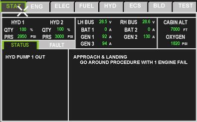
38 CABIN VARIOMETER INDICATIONS STAT synoptic STAT SYNOPTIC Page 37
39 SYSTEM PROTECTION CIRCUIT BREAKERS The electrical circuit protection is provided by conventional trip-free circuit breakers located above the overhead panel (refer to Air conditioning). PRESSURIZATION SYSTEM PROTECTION Pressurization system protection consists of maximum differential pressure limitation, negative differential pressure prevention and cabin altitude limitation. Each outflow valve performs all protections. Maximum differential pressure limitation The CPC automatically maintains a normal differential pressure limit of 9,3 psi. An overpressure limitation capsule, located in each outflow valve, controls the maximum cabin differential pressure at 9.6 psi. Maximum cabin altitude limitation An altitude limitation capsule contained in each outflow valve maintains the cabin pressure altitude of 14,500 ft in case of depressurization due to: - CPC failure, - DUMP pushbutton activation, - permanent cabin rate of climb in manual mode. Negative differential pressure prevention The negative pressure relief valve protects the structure from the effects of negative differential pressure (external pressure above cabin pressure). Only negative pressure relief valve can override the maximum cabin altitude limitation. BAGGAGE COMPARTMENT PRESSURE RELIEF VALVES Positive and negative pressure relief valves are installed in the baggage compartment. If the heating valve fails to close when the BAG pushbutton is activated the positive pressure relief valves limits the baggage compartment-to-cabin pressure differential at 0.07 psi. When the baggage compartment is isolated, negative differential pressure during descent is prevented by the negative pressure relief valves, which open when the baggage compartment-to-cabin pressure differential reaches 0.28 psi. NOSE CONE BULKHEAD PRESSURE RELIEF VALVE A pressure relief valve in the nose cone bulkhead provides structural protection in case the calibrated holes provided for airflow evacuation are clogged. The relief valve is intended to operate when the difference between nose cone pressure and atmospheric pressure reaches 1.37 psi. Page 38
40 NORMAL OPERATION In the following, typical in-flight situation has been selected to help the crew to understand the symbols provided in the various panels and displays. OVERHEAD PANEL ECS SYNOPTIC Page 39
41 ABNORMAL OPERATION INTRODUCTION In the following, abnormal operation has been selected to help the crew to understand the symbols provided in the various panels and displays. PRESSURIZATION WITH COMPUTER FAILURE Abnormal status ECS SYNOPTIC CONTEXT RESULT CABIN Pressure Control System (CPCS) failure PRESSURE CMPTR FAIL + MASTER CAUTION light on CAS message Page 40


 - Target altitude is pointed in magenta on the left side of the")
42 After procedure complete PRESSURIZATION OVERHEAD PANEL MANUAL PRESSURIZATION CONTROL KNOB ECS SYNOPTIC ACTION Manual pressurization control knob set to the white area PRESSU pushbutton depressed RESULT - Pressurization in manual mode - Emergency outflow valve becomes the master valve - MAN status light in amber Manual pressurization control knob adjusted (turned counterclockwise to decrease cabin altitude) - Target altitude is pointed in magenta on the left side of the altitude scale Page 41
43 CAS MESSAGES CAS MESSAGE CABIN ALTITUDE BAG ISOL DEFINITION Cabin altitude above 9,700 +/- 500 ft excepted in hight altitude landing and take-off Baggage compartment is isolated CABIN PRESSURE TOO HIGH cabin above 9.7 psi CABIN SELECT LAND ELEV CHECK CABIN ALTITUDE PRESSURE CMPTR FAIL CHECK CABIN RATE No landing elevation selected when starting descent Cabin altitude above 8,200 ft Pressurization computer failure Vzcab < - 1,200 ft/mn or Vzcab > 1,200 ft/mn Page 42
ENVIRONMENTAL CONTROL SYSTEM (ECS)
") ENVIRONMENTAL CONTROL SYSTEM (ECS) DESCRIPTION AND OPERATION The ECS system comprises the following subsystems: bleed air management, environmental control unit (ECU) temperature control air distribution
ENVIRONMENTAL CONTROL SYSTEM (ECS) DESCRIPTION AND OPERATION The ECS system comprises the following subsystems: bleed air management, environmental control unit (ECU) temperature control air distribution
DASSAULT AVIATION Proprietary Data
 FALCON 7X 02-36-05 CODDE 1 PAGE 1 / 4 GENERAL ACRONYM LIST A/I AMM AMSAC AMSEC APU BALDS BAS BLD CB ECS EMM HP LCV LP MP OP PAX PCS PRSOV SOV SSPC T/O WAI XBLEED Anti-Ice Air Management Module Air Management
AIR CONDITIONING AND PRESSURIZATION CONTROLS AND INDICATORS
 AIR CONDITIONING AND PRESSURIZATION CONTROLS AND INDICATORS Air conditioning control panel 1 MIN MAX Page 1 Air conditioning control panel 2 MIN MAX Page 2 Air conditioning control panel 3 MIN MAX Page
Section - III SYSTEMS DESCRIPTION
 Section - III SYSTEMS DESCRIPTION Pro Line 21 Table of Contents Page GENERAL... 10-3 BLEED AIR SYSTEM... 10-3 ENGINE AIR BLEED... 10-3 MIXING VALVE... 10-3 MAIN AIR VALVE... 10-3 PRESSURE REGULATOR and
Fokker 50 - Air Conditioning & Pressurization
 AIR CONDITIONING General Pressure regulated engine bleed-air is cooled and temperature regulated in two air conditioning packs. The temperature-regulated airflow can be mixed with recirculated cabin air.
NO SMOKING WHEN OXYGEN IS IN USE.
 GENERAL NO SMOKING WHEN OXYGEN IS IN USE. The oxygen system provides oxygen as required for up to 19 passengers and 2 cockpit crew members. Therapeutic oxygen outlets are also available in the cabin. OXYGEN
NO SMOKING WHEN OXYGEN IS IN USE.
 OXYGEN SYSTEM DESCRIPTION NO SMOKING WHEN OXYGEN IS IN USE. Oxygen for flight crew and passengers is supplied by a 77 cu ft high pressure (1850 psi) cylinder, located in the right side of the nose compartment.
EMERGENCY EQUIPMENT Table of Contents CHAPTER 8 - EMERGENCY EQUIPMENT
 Table of Contents 08 00 1 CHAPTER 8 - EMERGENCY EQUIPMENT TABLE OF CONTENTS Page TABLE OF CONTENTS DESCRIPTION General Oxygen System Components and Operation Controls and Indicators Crew Oxygen Consumption
DASSAULT AVIATION Proprietary Data
 FALCON 7X 02-35-05 CODDE 1 PAGE 1 / 4 GENERAL ACRONYM LIST ALTI CAS CB ECS EFCU HP LP MDU NAV O2 O'RIDE PAX PSU SSPC QTY Altitude Crew Alerting System Circuit Breaker Environmental Control System Electrical
AIR CONDITIONING/PRESSURIZATION
 Table of Contents Introduction... 02-01-01 Bleed Air System... 02-02-01 Description... 02-02-01 Bleed Air Distribution... 02-02-02 Description... 02-02-02 Components And Operation...02-02-02 Bleed Air
CHAPTER 17 MISCELLANEOUS SYSTEMS
 CHAPTER 17 MISCELLANEOUS SYSTEMS INTRODUCTION This chapter covers the oxygen system and squat switch (weight-on-wheels sensing) systems on the Citation Mustang. Oxygen is available to the crew and passengers
CHAPTER EMERGENCY EQUIPMENT
 Vol. 1 09--00--1 EMERGENCY EQUIPMENT Table of Contents REV 3, May 03/05 CHAPTER 9 --- EMERGENCY EQUIPMENT Page TABLE OF CONTENTS 09-00 Table of Contents 09--00--1 INTRODUCTION 09-10 Introduction 09--10--1
EMERGENCY EQUIPMENT TABLE OF CONTENTS CHAPTER 8
 TABLE OF CONTENTS CHAPTER 8 Page TABLE OF CONTENTS DESCRIPTION General Placards Oxygen Flight Compartment Oxygen Bottle Oxygen Ground Service Panel Crew Mask Storage Crew Mask Passenger Oxygen Oxygen System
AIRCRAFT SYSTEMS AIR CONDITIONING / PRESSURIZATION / VENTILATION
 AIR CONDITIONING / PRESSURIZATION / VENTILATION Intentionally left blank PRELIMINARY PAGES - TABLE OF CONTENTS DSC-21-10 Air Conditioning DSC-21-10-10 General General...A Architecture... B 1 DSC-21-10-20
Fuselage, Wings and Stabilising Surfaces
 Fuselage, Wings and Stabilising Surfaces Chapter 1 DESIGN PHILOSOPHIES The aircraft manufacturer will attempt to design an aircraft to take into account all the loads that it may experience in flight.
SECTION 6-16 FLIGHT INSTRUMENTS
 SECTION 6-16 SYSTEMS DESCRIPTION Index Page Pitot-Static System... 6-16-2 Airspeed Indicator... 6-16-4 Vertical Speed Indicator... 6-16-4 Instantaneous Vertical Speed Indicator IVSI (Optional)... 6-16-5
BASIC AIRCRAFT STRUCTURES
 Slide 1 BASIC AIRCRAFT STRUCTURES The basic aircraft structure serves multiple purposes. Such as aircraft aerodynamics; which indicates how smooth the aircraft flies thru the air (The Skelton of the aircraft
SUPPLEMENT SEPTEMBER 2010 HIGH ALTITUDE TAKEOFF AND LANDING (ABOVE 14,000 FEET PRESSURE ALTITUDE) MODEL AND ON 68FM-S28-00 S28-1
 MODEL AND ON 68FM-S28-00 S28-1") MODEL 680 680-0001 AND ON HIGH ALTITUDE TAKEOFF AND LANDING (ABOVE 14,000 FEET PRESSURE ALTITUDE) COPYRIGHT 2010 CESSNA AIRCRAFT COMPANY WICHITA, KANSAS, USA 15 SEPTEMBER 2010 S28-1 SECTION V - SUPPLEMENTS
MODEL 680 680-0001 AND ON HIGH ALTITUDE TAKEOFF AND LANDING (ABOVE 14,000 FEET PRESSURE ALTITUDE) COPYRIGHT 2010 CESSNA AIRCRAFT COMPANY WICHITA, KANSAS, USA 15 SEPTEMBER 2010 S28-1 SECTION V - SUPPLEMENTS
DESCRIPTION AND OPERATION OXYGEN SYSTEM OXYGEN SYSTEM
 2.20. 2.20.1 EMERGENCY SUPPLEMENTARY OXYGEN WARNING Positively NO SMOKING while oxygen is being used by anyone in the airplane. Keep the entire system free from oil and grease (to avoid the danger of spontaneous
FLOW LIMITER 5% VENTURI 5 PSID TO ENGINE ANTI-ICE OVERBOARD PAC BLD SELECT HP LP NORM ISOLATION VALVE TO SERVICE AIR FROM APU (TYPICAL) 5 PSID
 5 PSID") Bleed Air System LEF FEED BUS LEF CB PANEL CKP EMP SEL 1 COLD HO CKP CAB COLD HO MANUAL SEL SEL MANUAL CKP PAC SUPPLY SUPPLY CAB PAC ON OFF HIGH OFF ON HIGH 3 ISOL VALVE 4 OFF 5 AUO ON EMER L ENG BLD AIR
Bleed Air System LEF FEED BUS LEF CB PANEL CKP EMP SEL 1 COLD HO CKP CAB COLD HO MANUAL SEL SEL MANUAL CKP PAC SUPPLY SUPPLY CAB PAC ON OFF HIGH OFF ON HIGH 3 ISOL VALVE 4 OFF 5 AUO ON EMER L ENG BLD AIR
A AMM - ENGINE BLEED AIR SUPPLY SYSTEM - DESCRIPTION AND OPERATION
 FED 401-405,407-414,423-436,442-443,445 ENGINE BLEED AIR SUPPLY 1. General The system is designed to : - select the compressor stage from which air is bled, depending on the pressure and/or temperature
8 - CONTENTS SECTION 8. TABLE OF CONTENTS Page LIST OF ILLUSTRATIONS. Figure Title Page Number. 1 Crew Oxygen System (2 Sheets) 4.
 4.") EMERGENCY EQUIPMENT TABLE OF CONTENTS Page 1. CREW OXYGEN SYSTEM 1 2. EMERGENCY EXITS 2 3. PORTABLE FIRE EXTINGUISHER 3 4. EMERGENCY LIGHTING 3 LIST OF ILLUSTRATIONS Figure Title Page Number 1 Crew Oxygen
EMERGENCY EQUIPMENT TABLE OF CONTENTS Page 1. CREW OXYGEN SYSTEM 1 2. EMERGENCY EXITS 2 3. PORTABLE FIRE EXTINGUISHER 3 4. EMERGENCY LIGHTING 3 LIST OF ILLUSTRATIONS Figure Title Page Number 1 Crew Oxygen
Bombardier Global Express - Integrated Air Management System INTRODUCTION
 TRODUCTION AIR SYSTEM The Bleed Air System is controlled during all phases of operation by two Bleed Management Controllers (BMC). The BMCs provide indications and warnings to EICAS and maintenance information
OPERATING MANUAL PSP 601A-6
 OPERATING MANUAL 1. AIR CONDITIONING AIR CQNPITIONING/PRESSURIZATION TABLE OF CONTENTS Page A. General 1 B. Bleed Air Control System 1 C. Air Conditioning Units (ACU) 1 D. Distribution Ducting 3 E. Temperature
FLUID POWER FLUID POWER EQUIPMENT TUTORIAL OTHER FLUID POWER VALVES. This work covers part of outcome 2 of the Edexcel standard module:
 FLUID POWER FLUID POWER EQUIPMENT TUTORIAL OTHER FLUID POWER VALVES This work covers part of outcome 2 of the Edexcel standard module: UNIT 21746P APPLIED PNEUMATICS AND HYDRAULICS The material needed
Dash8 - Q400 - Oxygen
 12.16 (ATA 35) OXYGEN 12.16.1 Introduction There is a fixed oxygen system for the flight deck crew and observer. Separate portable oxygen systems are supplied for the cabin attendants and passengers. Separate
This test shall be carried out on all vehicles equipped with open type traction batteries.
 5.4. Determination of hydrogen emissions page 1 RESS-6-15 5.4.1. This test shall be carried out on all vehicles equipped with open type traction batteries. 5.4.2. The test shall be conducted following
OPERATION MANUAL NTF-15
 OPERATION MANUAL NTF-15 Nitrogen Tire Filling Valve Stem Caps (Qty=200) Order P/N 436075 RTI Technologies, Inc 10 Innovation Drive York, PA 17402 800-468-2321 www.rtitech.com 035-81235-00 (Rev B) TABLE
MASTER MINIMUM EQUIPMENT LIST (MMEL): MAINTENANCE AND OPERATIONS (M & O) PROCEDURES MANUAL FOR THE CIRRUS VISION SF50
: MAINTENANCE AND OPERATIONS (M & O) PROCEDURES MANUAL FOR THE CIRRUS VISION SF50") MASTER MINIMUM EQUIPMENT LIST (MMEL): MAINTENANCE AND OPERATIONS (M & O) PROCEDURES MANUAL FOR THE CIRRUS CIRRUS AIRCRAFT 4515 Taylor Circle Duluth, MN 55811 FAA APPROVAL HAS BEEN OBTAINED ON THE TECHNICAL
MASTER MINIMUM EQUIPMENT LIST (MMEL): MAINTENANCE AND OPERATIONS (M & O) PROCEDURES MANUAL FOR THE CIRRUS CIRRUS AIRCRAFT 4515 Taylor Circle Duluth, MN 55811 FAA APPROVAL HAS BEEN OBTAINED ON THE TECHNICAL
Lesson 6: Flow Control Valves
 : Flow Control Valves Basic Hydraulic Systems Hydraulic Fluids Hydraulic Tank Hydraulic Pumps and Motors Pressure Control Valves Directional Control Valves Flow Control Valves Cylinders : Flow Control
ANNEX AMENDMENTS TO THE INTERNATIONAL CODE FOR FIRE SAFETY SYSTEMS (FSS CODE) CHAPTER 15 INERT GAS SYSTEMS
 CHAPTER 15 INERT GAS SYSTEMS") Annex 3, page 2 ANNEX AMENDMENTS TO THE INTERNATIONAL CODE FOR FIRE SAFETY SYSTEMS (FSS CODE) CHAPTER 15 INERT GAS SYSTEMS The text of existing chapter 15 is replaced by the following: "1 Application This
Annex 3, page 2 ANNEX AMENDMENTS TO THE INTERNATIONAL CODE FOR FIRE SAFETY SYSTEMS (FSS CODE) CHAPTER 15 INERT GAS SYSTEMS The text of existing chapter 15 is replaced by the following: "1 Application This
Chapter 10: Bidirectional Flow Controls
 Chapter 10: Bidirectional Flow Controls Objectives Learn about the patented, bidirectional flow control valves. Understand how the flow force affects the performance of the ZL70-36. Learn why there is
ATL R/V Atlantis AUXILIARY PLANT OPERATION APPENDIX OPERATING PROCEDURES
 110 AIR CONDITIONING CHILLED WATER PLANT 1. Ensure power to water chiller controller and all fan coil unit controllers is on 2. Ensure chilled water expansion tank level is at its proper level 3. Ensure
Time-Delay Electropneumatic Applications
 Exercise 3-4 EXERCISE OBJECTIVE & & & To introduce time delays; To describe the operation of a time-delay valve; To describe the operation of a time-delay relay. DISCUSSION Time-Delays Time delays are
Waterous Relief Valve
 Operating Instructions 1. Reduce pump discharge pressure with engine throttle. Make sure four way (On/Off) valve is OFF. 2. Open at least one discharge valve. Accelerate engine until pressure gage indicates
VACUUM REGULATORS CONTENTS
 CAD drawing data catalog is available. ACCESSORIES GENERAL CATALOG AIR TREATMENT, AUXILIARY, VACUUM, AND FLUORORESIN PRODUCTS CONTENTS Small Regulators Features 759 Specifications, Order Codes, Flow Rate
Flight Control Systems Introduction
 Flight Control Systems Introduction Dr Slide 1 Flight Control System A Flight Control System (FCS) consists of the flight control surfaces, the respective cockpit controls, connecting linkage, and necessary
Modulating Valves for Atmospheric, Infrared, and Direct Fired Burners
 BULLETIN MT2035-07/05 Modulating Valves for Atmospheric, Infrared, and Direct Fired Burners M/MR Series M411, M511, M611 M420, M520, M620, MR410, MR510, MR610 MR212D, MR212E, MR212G and MR212J (Flanged),
Constant Pressure Inlet (CCN) Operator Manual
 Operator Manual") Constant Pressure Inlet (CCN) Operator Manual DOC-0125 Revision J 2545 Central Avenue Boulder, CO 80301-5727 USA C O P Y R I G H T 2 0 1 1 D R O P L E T M E A S U R E M E N T T E C H N O L O G I E S, I
Constant Pressure Inlet (CCN) Operator Manual DOC-0125 Revision J 2545 Central Avenue Boulder, CO 80301-5727 USA C O P Y R I G H T 2 0 1 1 D R O P L E T M E A S U R E M E N T T E C H N O L O G I E S, I
The Discussion of this exercise covers the following points: Range with an elevated or suppressed zero Suppressed-zero range Elevated-zero range
 Exercise 4-3 Zero Suppression and Zero Elevation EXERCISE OBJECTIVE In this exercise, you will learn the effect that mounting a pressure transmitter above or below the reference level has on the hydrostatic
DAHER-SOCATA Customer Support. TBM700 - TBM850 - TBM900 Review of high altitude operations
 DAHER-SOCATA Customer Support TBM700 - TBM850 - TBM900 Review of high altitude operations 2014-008 September 24, 2014 Dear Owners, Operators and Network members, This Service Information is for general
OPERATION MANUAL NTF-60 Plus
 OPERATION MANUAL NTF-60 Plus Nitrogen Tire Filling Valve Stem Caps (Qty=200) Order P/N 436075 RTI Technologies, Inc 10 Innovation Drive York, PA 17402 800-468-2321 www.rtitech.com 035-81264-00 (Rev A)
XDF BURNERS DUAL FUEL EXCESS AIR BURNER FEATURES DESCRIPTION EXCESS AIR OPERATION
 DUAL FUEL EXCESS AIR BURNER MODEL: 3610, 3651 Revision: 0 FEATURES Burns all fuel gases or light oils Nozzle mix design for on ratio control or excess air 350% excess air all sizes on gas or oil Turndown
S-TEC. Pilot s Operating Handbook
 S-TEC Pilot s Operating Handbook List of Effective Pages * Asterisk indicates pages changed, added, or deleted by current revision. Retain this record in front of handbook. Upon receipt of a Record of
The Military CYPRES Quick Guide For Operators
 The Military CYPRES Quick Guide For Operators The military CYPRES is available in the following standard models: All models can be adapted with a one or two-pin cutter. 1000/35 A 1500/35 A 1000/35 indicates
Revision Number Revision Date Insertion Date/Initials 1 st Ed. Oct 26, 00 2nd Ed. Jan 15, 08
 List of Effective Pages * Asterisk indicates pages changed, added, or deleted by current revision. Retain this record in front of handbook. Upon receipt of a Record of Revisions revision, insert changes
BUBBLER CONTROL SYSTEM
 BUBBLER CONTROL SYSTEM Description: The HDBCS is a fully automatic bubbler system, which does liquid level measurements in water and wastewater applications. It is a dual air compressor system with, air
TECHNICAL DATA SINGLE INTERLOCKED PREACTION SYSTEM WITH PNEUMATIC RELEASE
 1 of 10 1. DESCRIPTION (Refer to Figures 1-3.) Viking supervised Single Interlocked Preaction Systems utilize a Viking Deluge Valve and a pneumatically pressurized automatic sprinkler system. The system
ROTORCRAFT FLIGHT MANUAL SUPPLEMENT. TO THE BELL MODEL UH-1H ROTORCRAFT FLIGHT MANUAL for the APICAL EMERGENCY FLOAT KIT
 SUPPLEMENT TO THE for the APICAL EMERGENCY FLOAT KIT This supplement is to be used when the rotorcraft is modified by the installation of the Apical Float Kit 644.3201 for UH-1H helicopters. The information
Discharge Relief Valve Operation & Maint.
 Relief Valve Operation & Maint. CZ Series Centrifugal Fire Relief svalve Operation and Maintenance Instructions 1410 Operation and Maintenance Form No. F-1031 Section 2302.6 2111 Issue Date 04/90 11/95
CSC-2000 SERIES. Reset Volume Controllers MADE IN U.S.A. DESCRIPTION MODELS SPECIFICATIONS ORDERING
 CSC-2000 SERIES Reset Volume Controllers MADE IN U.S.A. DESCRIPTION The CSC-2000 series are designed for use on VAV terminal units in HVAC systems. These are submaster air velocity controllers whose velocity
Pressure Automated Calibration Equipment
 GE Measurement & control Pressure Automated Calibration Equipment Safety Instructions and User Guide - K0447 PACE5000 PACE6000 K0447 Issue No. 9 1 10 1 PACE5000 1 2 3 4 5 PACE6000 2 6 7 8 3 4 5 6 7 8 9
Pitot-Static System - Inspection/Check ICA Supplement
 AIRCRAFT DIVISION WICHITA, KANSAS 67277 Pitot-Static System - Inspection/Check ICA Supplement MODEL NO: 680A SUPPLEMENT NO: ICA-680A-34-00001 SUPPLEMENT DATE: 1/22/2016 Cessna Aircraft Company Form 2261
Model 130M Pneumatic Controller
 Instruction MI 017-450 May 1978 Model 130M Pneumatic Controller Installation and Operation Manual Control Unit Controller Model 130M Controller is a pneumatic, shelf-mounted instrument with a separate
The Discussion of this exercise covers the following points: Pumps Basic operation of a liquid pump Types of liquid pumps The centrifugal pump.
 Exercise 2-3 Centrifugal Pumps EXERCISE OBJECTIVE In this exercise, you will become familiar with the operation of a centrifugal pump and read its performance chart. You will also observe the effect that
MANUAL BE SERIES Test Benches
 The CustomCrimp Manual BE Series Test Benches are designed with features that make proof and burst testing of hydraulic hose assemblies a quick and easy procedure. CUSTOMIZED AND SPECIAL DESIGN BENCHES
Cover Page for Lab Report Group Portion. Pump Performance
 Cover Page for Lab Report Group Portion Pump Performance Prepared by Professor J. M. Cimbala, Penn State University Latest revision: 02 March 2012 Name 1: Name 2: Name 3: [Name 4: ] Date: Section number:
Operation & Maintenance Manual Place this manual with valve or person responsible for maintenance of the valve
 Operation & Maintenance Manual Place this manual with valve or person responsible for maintenance of the valve Model CYCLE GARD II, CI & CNA YOUR PRODUCT INFORMATION: Model Number: Date: Serial Number:
General. Procedure Checklists. Emergency Procedures. FSD Aerostar 700P Superstar
 General The recommended procedures for coping with various types of emergencies and critical situations are provided in this section. These procedures are suggested as a course of action for coping with
Welker Sampler. Model GSS-1. Installation, Operation, and Maintenance Manual
 Installation, Operation, and Maintenance Manual Welker Sampler Model GSS-1 The information in this manual has been carefully checked for accuracy and is intended to be used as a guide to operations. Correct
Reclaim Basic Set Up
 This purpose of the document is to simplify the set up and understand the Gas Services reclaim system functions. The Gas Services Reclaim Manual is to be used for reference, maintenance, and servicing.
ACCESSORY KIT INSTALLATION INSTRUCTIONS
 ACCESSORY KIT INSTALLATION INSTRUCTIONS 1NP0680 - PROPANE CONVERSION FOR USE WITH MODELS: PM8, PC8, PM9, PC9, FL9M, FL9C, FC9M, FC9C This conversion kit is to be installed by a qualified service agency
Contents. Catalog HY /US Load and Motor Control Valves SERIES CAVITY DESCRIPTION FLOW PRESSURE PAGE NO. LPM/GPM BAR/PSI
 Load and Motor Control Contents SERIES CAVITY DESCRIPTION FLOW PRESSURE PAGE NO. LPM/GPM BAR/PSI STANDARD PILOT ASSISTED CB101... C10-3... Load Control Cartridge Valve...45/12... 380/5500... 5-6 MHC-010-S***
CSC-2000 SERIES. Reset Volume Controllers MADE IN U.S.A. DESCRIPTION MODELS SPECIFICATIONS ORDERING
 CSC-2000 SERIES Reset Volume Controllers MADE IN U.S.A. DESCRIPTION The CSC-2000 series are designed for use on VAV terminal units in HVAC systems. These are submaster air velocity controllers whose velocity
BUBBLER CONTROL SYSTEM
 BUBBLER CONTROL SYSTEM Description: The LDBCS is a fully automatic bubbler system, which does liquid level measurements in water and wastewater applications. It is a dual air compressor system with, air
Components for air preparation and pressure adjustment. OUT port position ( ) connected Rear side. of IN port. Air tank. directly.
 connected Rear side. of IN port. Air tank. directly.") Components preparation and pressure adjustment ABP Overview ABP is a component that enables boosting by s only up to twice primary pressure (.0MPa max.) in combination with using air tank but not using
Components preparation and pressure adjustment ABP Overview ABP is a component that enables boosting by s only up to twice primary pressure (.0MPa max.) in combination with using air tank but not using
USER S INFORMATION MANUAL
 USER S INFORMATION MANUAL UPFLOW, DOWNFLOW, UPFLOW/HORIZONTAL & HORIZONTAL ONLY INDUCED DRAFT GAS FURNACES Recognize this symbol as an indication of Important Safety Information If the information in this
Depressurization in Cruise, Aer Lingus Boeing , EI-CDD, north of Paris, December 9, 2000
 Depressurization in Cruise, Aer Lingus Boeing 737-500, EI-CDD, north of Paris, December 9, 2000 Micro-summary: Mechanical failures result in a pressurization failure on this Boeing 737-500. Event Date:
Operation Manual. Diaphragm Sensed Gas Pressure Regulators
 687 Technology Way Napa, CA 94558 Phone: (707) 259-0102 FAX: (707) 259-0117 www.aptech-online.com Diaphragm Sensed Gas (AP/AZ/AK Models: 20, 100, 500, 1000, 1000T 10PA, 1100, 1200, 12PA, 1300, 1400T, 14PA,
PNEUMATIC PRESSURE CONTROLLERS
 PNEUMATIC PRESSURE CONTROLLERS VARIABLE VOLUME PRESSURE CONTROLLER MODELS: V-1 R AND V-2R The 3D Variable Volume Pressure Controller is available for requirements of 0-1,000 psi and 0-6,000 psi in absolute
Pneumatic high-pressure controller Model CPC7000
 Calibration technology Pneumatic high-pressure controller Model CPC7000 WIKA data sheet CT 27.63 Applications Healthcare and avionics industry Industry (laboratory, workshop and production) Transmitter
ANTI SHOCK RELIEF VALVE
 ANTI SHOCK RELIEF VALVE Wheeler Road Coventry CV3 4LA England Brüsseler Allee 2 D-41812 Erkelenz Tel. +44(0)2476-217-400 Fax +44(0)2476-217-488 Tel. +49(0)24 31-80 91-0 Fax +49(0)24 31-80 91-19 www.sunhydraulics.com
Digester Processes. 1. Raw Sludge Pumping System
 Digester Processes 1. Raw Sludge Pumping System Removes accumulated sludge from the primary clarifiers, pumped through 1 of 2 pipes either 150 or 200mm in diameter (Fig. 1.1). Fig 1.1 Pipes feeding Digesters
Ventam 85 Installation & Commissioning Instructions
 Ventam Systems Ltd Unit D4 Seedbed Business Centre Vanguard Way Shoeburyness Essex SS3 9QY Phone 01702 382 307 Fax 01702 382 340 Ventam 85 Installation & Commissioning Instructions 1 General The Ventam
Maximum 0.85 MPa pressure setting Long-life, high flow perfect for balancer applications
 Outstanding performance in extremely low pressure and low pressure ranges from 0.003 to. Realizing high performance, energy saving, and compact size. Realize precise pressure control in a pressure range
CHEMICAL ENGINEERING LABORATORY CHEG 239W. Control of a Steam-Heated Mixing Tank with a Pneumatic Process Controller
 CHEMICAL ENGINEERING LABORATORY CHEG 239W Control of a Steam-Heated Mixing Tank with a Pneumatic Process Controller Objective The experiment involves tuning a commercial process controller for temperature
Exercise 4-2. Centrifugal Pumps EXERCISE OBJECTIVE DISCUSSION OUTLINE DISCUSSION. Pumps
 Exercise 4-2 Centrifugal Pumps EXERCISE OBJECTIVE Familiarize yourself with the basics of liquid pumps, specifically with the basics of centrifugal pumps. DISCUSSION OUTLINE The Discussion of this exercise
Principle of Operation. Features. Applications. CL34 Operating Schematic
 ..GAS.REGS..GAS.REGS Principle of Operation (See Operating Schematic below) pressure connected by tubing to the pilot regulator, is utilized as supply pressure for pilot. pressure of the Regulator is applied
SUPER PRECISION AIR RELAYS
 CAT. No. KS-128E SUPER PRECISION AIR REGULATOR rsseries SUPER PRECISION AIR REGULATORS rr SERIES SUPER PRECISION AIR RELAYS Air Pressure Regulators that attain the ultimate in pressure control. S/R R SUPER
LENNOX SLP98UHV DIAGNOSTIC CODES
 Code Status of Equipment Action required to clear and recover - Idle mode (Decimal blinks at 1 Hertz -- 0.5 second ON, 0.5 second OFF) A Cubic feet per minute (cfm) setting for indoor blower (1 second
COMPARING PLUG & SEAT REGULATORS & CONTROL VALVES. Lamar Jones. Equipment Controls Company 4555 South Berkeley Lake Road Norcross, GA 30071
 COMPARING PLUG & SEAT REGULATORS & CONTROL VALVES Lamar Jones Equipment Controls Company 4555 South Berkeley Lake Road Norcross, GA 30071 INTRODUCTION The purpose of this paper will be to compare a plug
CHE Well Testing Package/Service:
 CHE Well Testing Package/Service: CHE delivers well testing package And services, trailer mounted well testing package and offshore/onshore well testing services with over 10 years experience. Our testing
RAM 4021-DPX Operation Manual
 RAM 4021-DPX Operation Manual Worldwide Manufacturer of Gas Detection Solutions TABLE OF CONTENTS ABL 4021-DPX / RAM 4021-DPX For Your Safety... 3 Description... 3 Setup Mode... 4 Lights/Alarms... 4 Operation...
5 Function Indicator. Outside Air Temperature (C) Outside Air Temperature (F) Pressure Altitude Density Altitude Aircraft Voltage STD TEMP SL 15000
 Outside Air Temperature (F) Pressure Altitude Density Altitude Aircraft Voltage STD TEMP SL 15000") 5 Function Indicator +20 +40-5000 STD TEMP SL 15000 Outside Air Temperature (C) Outside Air Temperature (F) Pressure Altitude Density Altitude Aircraft Voltage 427 HILLCREST WAY REDWOOD CITY, CA 94062
5 Function Indicator +20 +40-5000 STD TEMP SL 15000 Outside Air Temperature (C) Outside Air Temperature (F) Pressure Altitude Density Altitude Aircraft Voltage 427 HILLCREST WAY REDWOOD CITY, CA 94062
«DO160/ED14» - Jessica France
 Training Workshop «DO160/ED14» - Jessica France DO160/ED14 Specificities of Mechanical and Climatic aspects Edouard ZUNDEL Systems Qualification Engineer for Mechanical and Climatic aspects 1 The reference
I T T Pressure Reducing Valve WARNING INSTALLATION, OPERATION, AND MAINTENANCE MANUAL
 INSTALLATION, OPERATION, AND MAINTENANCE MANUAL I-867-4T 867-4T Pressure Reducing Valve HANG THESE INSTRUCTIONS ON THE INSTALLED VALVE FOR FUTURE REFERENCE WARNING Read and understand all instructions
BACK PRESSURE / SUSTAINING
 In many liquid piping systems, it is vital that line pressure is maintained within relatively narrow limits. This is the function of the 108 Pressure Relief / Back Pressure Series of the OCV control valves.
R E D I C O N T R O L S
 R E D I C O N T R O L S Operation & Maintenance Manual Portable Service Purger for Low Pressure Chillers Model: PSP-LP-1B For Refrigerants R-11, R-113, R-114 & R-123 & Other Similar Refrigerants File Literature
Technical Knowledge and Aerostatics (Balloon) This syllabus presupposes a knowledge and understanding already attained at PPL level.
 This syllabus presupposes a knowledge and understanding already attained at PPL level.") Subject No 29 Technical Knowledge and Aerostatics (Balloon) Note: This syllabus is primarily based on a balloon designed above 120000 cubic feet maximum. Each subject has been given a subject number and
Subject No 29 Technical Knowledge and Aerostatics (Balloon) Note: This syllabus is primarily based on a balloon designed above 120000 cubic feet maximum. Each subject has been given a subject number and
P r o d u c t R a n g e Data sheet: P
 P r o d u c t R a n g e Data sheet: P245423-10 Pressure Reducing Maintains a constant downstream pressure regardless of upstream pressure or flow rate fluctuations. The set point of reduced pressure is
Installation Instructions
 Page 5750-S-1 Installation Instructions General These mounting instructions for Circular INCINO- PAK Burners are in addition to the specific instructions offered for other Maxon component items: Shut-Off
HS653 Negative Pressure Ventilation Controller
 HS653 Negative Pressure Ventilation Controller General Installation Notes: Make sure that power is disconnected from system prior to servicing. Installation of this equipment and related OEM equipment
PITOT STATIC TEST EQUIPMENT PRODUCT CATALOG. Testing, Tools and Ground Support Equipment
 PITOT STATIC TEST EQUIPMENT PRODUCT CATALOG Testing, Tools and Ground Support Equipment WE SUPPLY, TO KEEP THEM Flying In the aviation industry, precision and support are of vital importance. This is why
The Discussion of this exercise covers the following points:
 Exercise 5-3 Wet Reference Leg EXERCISE OBJECTIVE Learn to measure the level in a vessel using a wet reference leg. DISCUSSION OUTLINE The Discussion of this exercise covers the following points: Measuring
GW DRY PIPE VALVE INSTALLATION & OPERATION 100mm (4 ) 150mm (6 )
 150mm (6 )") Read in conjunction with Dry Valve Set Schematic (section 7). 1. PRINCIPLE OF OPERATION. Primary functions of the Angus Type D dry alarm valve station: 1.1. To maintain a dry sprinkler pipework system
Read in conjunction with Dry Valve Set Schematic (section 7). 1. PRINCIPLE OF OPERATION. Primary functions of the Angus Type D dry alarm valve station: 1.1. To maintain a dry sprinkler pipework system
Universal Valve Company Inc
 1975-FA34 (Air Tower Troubleshooting Manual) Overview This manual has been arranged as a tool for diagnosing, and repairing Universal Air Towers Please read closely to identify the components that are
Inert Air (N2) Systems Manual
 Systems Manual") INSTRUCTION MANUAL Inert Air (N2) Systems Manual N2-MANUAL 2.10 READ AND UNDERSTAND THIS MANUAL PRIOR TO OPERATING OR SERVICING THIS PRODUCT. GENERAL INFORMATION Positive pressure nitrogen gas pressurizing
INSTRUCTION MANUAL Inert Air (N2) Systems Manual N2-MANUAL 2.10 READ AND UNDERSTAND THIS MANUAL PRIOR TO OPERATING OR SERVICING THIS PRODUCT. GENERAL INFORMATION Positive pressure nitrogen gas pressurizing
RD(H)20/25 Pressure-Reducing Regulator User Manual
20/25 Pressure-Reducing Regulator User Manual") RD(H)20/25 Pressure-Reducing Regulator User Manual Read the complete manual before installing and using the regulator. 2 Safe Product Selection When selecting a product, the total system design must be
RD(H)20/25 Pressure-Reducing Regulator User Manual Read the complete manual before installing and using the regulator. 2 Safe Product Selection When selecting a product, the total system design must be
3 GALLON, OILLESS PANCAKE COMPRESSOR INSTRUCTIONS. Item #31289
 3 GALLON, OILLESS PANCAKE COMPRESSOR INSTRUCTIONS Item #31289 The EASTWOOD 3 GALLON, OILLESS PANCAKE COMPRESSOR, with an Integral Air Regulator, efficiently supplies all compressed air requirements for
Pneumatic high-pressure controller Model CPC7000
 Calibration technology Pneumatic high-pressure controller Model CPC7000 WIKA data sheet CT 27.63 Applications Automotive and avionics industry Industry (laboratory, workshop and production) Transmitter