5.2 Will implementation of API 53 increase the reliability of well control equipment, and thereby the safety? What advantages will there be
|
|
|
- Lionel James
- 6 years ago
- Views:
Transcription

1
2 Executive summery The goal with this thesis was to look into consequences for implementing the API 53 standard for Transocean Norway. As it looks today the new requirements in the API 53 will be implemented as internal requirements within Transocean. Transocean operates in all the major oil and gas markets in the world and cannot operate with different regulations for each area. There is as of today no indication of regulatory requirements to change in Norway as a consequence of the new API 53. There may however be an updated version of Det Norske Veritas (DNVs) offshore standard (OS) with regards to drilling plant. I will in this thesis look into what Transocean Norway have to do to be in compliance with the new Standard and thereby new internal requirements. To be able to find the what actions Transocean Norway have to do I have made a GAP analysis between the new API 53 and Transocean Well Control Handbook. This has been a comprehensive work and I will in this thesis look into the findings. The API 53 contains mostly good oil field practice which has not been stated as a standard in the past, but there are also new requirements especially with regards to backup systems and secondary control systems as Emergency Shut Down (ESD), Autoshear, Deadman and ROV intervention all as a consequence of Macondo. Testing procedures is also more comprehensive than before and there are both positive and negative sides with this. The main goal of a new standard like API 53 is increased reliability and safer operation on an oil rig. For 5 out of 7 rigs Transocean Norway will have to upgrade the Blow out preventers (BOPs) and associated equipment with new technical solutions which has to be provided and engineered by Original equipment manufacturers (OEMs). I will look into the different implications, challenges and advantages with an implementation. 1
3 Table of Contents Executive summery... 1 List of Figures... 4 List of Tables... 4 Acknowledgment... 5 Glossary Problem description Introduction and background Problem description Main objectives and sub objectives Main objective Sub Objectives Project activities Research approach Teori Norwegian regulations DNV API Transocean Well control equipment management How a standard is followed in Transocean Methods Research design Data gathering Data analysis Analysis What does Transocean Norway need do to be in compliance? Emergency backup system Deadman and Autoshear Secondary control system - ROV intervention Secondary control system - Acoustic Control Systems Pressure test frequency
4 5.2 Will implementation of API 53 increase the reliability of well control equipment, and thereby the safety? What advantages will there be after implementation? Summary and Conclusion References Appendix
5 List of Figures Figur 1 DNV OS E101 International or national references Figur 2 There is expected implications of the implementation of the new standard Figur 3 Oceaneering Six shooter and high flow intervention panel (International, 2012) Figur 5 LMRP panel assembly Transoecan Leader List of Tables Tabell 1 GAP - BOP stack configuration Tabell 2 GAP - Autoshear and Deadman system Tabell 3 GAP - ROV Intervention Tabell 4 Quote from supplier of ROV high flow panel Tabell 5 GAP - Secondary control system Acoustic Tabell 6 Pre deployment surface testing according to API Tabell 7 Subsea pressure testing according to API
6 Acknowledgment I will thank Asgeir Lillejordet for guidance and support and the help he have given me by acting as guiding partner throughout this thesis, Henry Meling for many clarifying comments as a member of the API committee. Thank you to Steve Butler which has assisted me with solutions and quotes from suppliers as this upgrade will start on Transocean Leader in August/September. I will also thank Tore Markset for guidance and support with choosing topic of thesis and start up. This work is an independent thesis and do not necessarily reflect Transocean s view and is not written on behalf of Transocean as a company. 5
7 Glossary AOC - Acknowledgement of compliance ANSI American National Standard Institute API American Petroleum Institute BOP Blow Out Preventer BP British Petroleum BSR Blind Shear Ram BOEMRE Bureau of Ocean Energy Management, Regulation and Enforcement CMMS Computerized Maintenance Management System DEMAS - Deadman Autoshear DNV Det Norske Veritas DP Drill Pipe DP Dynamic Positioned DW Deep-water EDS Emergency Disconnect System GOM Gulf of Mexico HWDP Heavy Weight Drill Pipe ISO International Organization for Standardization LMRP Lower Marine Riser Package MASP - Maximum Anticipated Surface Pressure MAWHP Max Anticipated well head pressure MMS Mineral Management Service NCS - Norwegian continental shelf NOC National Oil Company NSA Norwegian Shipowners Association OLF Oljeindustirens landsforening OEM - Original Equipment Manufacture 6
8 OS Offshore Standard PR Pipe Ram PSAN Petroleum Safety Authority Norway ROV Remote Operated Vehicle RP Recommended Practice RWP Rated Work Pressure 7
9 1. Problem description 1.1 Introduction and background On April 20, people died in a blowout/explosion and a fire at the Macondo well operated by BP on Deepwater Horizon. One of the consequences was an oil spill which lasted until July 15 when a cap was installed. Not before 4 th of august tests showed that the well had reached a static condition. (BP, 2010)The quantity of oil released into the Gulf of Mexico is difficult to estimate, but it is undeniable that the blowout has caused significant losses on the regional tourism and fishing industries and damaged wildlife and the environment (Kritisne L. McAndrews, 2011) As a consequence of this incident the U.S government reacted with a 6 months moratorium on deep-water drilling and arctic drilling, to take a step back and look at the regulations. This was only the start when the US government started to look at the regulations. The Obama administration created a new Bureau of Ocean Energy Management, Regulation and Enforcement (BOEMRE) which replaced the old Mineral Management service (MMS). A bipartisan national commission on the BP oil spill and offshore drilling operations was established and tasked to provide recommendations on how the government can prevent similar incidents in the future. (Kritisne L. McAndrews, 2011) 8 th of June the United States department of the interior minerals management service issued National notice to lessees and operators of federal oil and gas leases, outer continental shelf (NTL No N05) the main points in this notice were: Recertification of Blow Out Preventer (BOP) (inspection & design review) Maintain BOP to American Petroleum Industry (API) standards Verification of Shearing capacity at Maximum Anticipated Surface Pressure (MASP) Autoshear and Deadman for DP vessels Remotely Operated Vehicle (ROV) minimum function (Lower Marine Riser Package (LMRP) Conn / Blind Shear Ram (BSR) / one Pipe Ram (PR)) ROV testing on surface Pull BOP after using shear rams Deadman subsea test ROV test subsea (one function per well) Personnel Trained in Deep-water (DW) well control (service, 2010) UK s Energy and climate change committee report recommended: 2 sets of shear rams 8
10 Inspection regime to avoid single point failure (specifically battery charge) General better spill prevention and response requirement And the Norwegian PSA has not initiated any technical changes. In the Norwegian regulation it is already a requirement for an alternative activation system for activating critical functions on the blowout preventer for use in the event of an evacuation on floating facilities. It is not stated what type to use but all rigs working on the Norwegian continental shelf has an acoustic system (Meling, 2012). PSA has identified three main subjects the industry needs to work with: organization and management risk management barrier management. (PSAN, 2012): One of the points in the BP investigation report under Operating Management System where BOP design and assurance. This is what this thesis will focus on. As a consequence of Macondo the different standard organizations started to review their relevant standards not only in the US but throughout the offshore industry. As the Macondo incident did not only affect the US but were a wakeup call for the whole industry. API has worked with changing the Recommended Practice (RP) 53 to a standard 53 as there is no API standard for the well control equipment except for the spec its built after at the time when it were new or after major upgrades. This meaning that a BOP built in 1983 is built after API spec at the time with the revision valid at the time. None of the new specs are retroactively, but is valid as of the date written on the front. 9
11 1.2 Problem description This thesis will look into the following problem description. What implications will implementation of API 53 have for Transocean Norway? What challenges will an implementation give? Sub problem descriptions: What does Transocean Norway need do to be in compliance? Will implementation of API 53 increase the reliability of well control equipment and thereby the safety of rig personnel? What advantages will there be after implementation? Prerequisite: 1. Only consequences for Transocean Norway 2. API 53 4 th ed Ballot 2 see comments under. Due to the balloting process for any API document is pretty rigid the Jan 16th vote was the 2nd Ballot and was accompanied by 300+ comments. The process require that every comment is reviewed and addressed one way or another and this needs to happen during a committee meeting (with quorum representation) The 1st ballot yielded in excess of 1000 comments and ultimately required the document to be re-written, hence the 2nd ballot. The 1st meeting to review the comments from ballot #2 will take place 27th March and it is hard to know how long it will take before all the comments are addressed and the document released. In particular some parts of the rules in API 53 Standard are very controversial and have generated a very significant push back of late from the industry (in particular the North Sea UK sector). Earliest publication of the standard is Q Only one shear ram for moored floaters as long as a written risk assessment is in place for each location. 4. Confidential due to above comment. 10
12 1.3 Main objectives and sub objectives Main objective The main objective with thesis is to establish what implication an implementation of API 53 will have for Transocean Norway Sub Objectives 1. To establish what standards Transocean follow to day. 2. To establish what Transocean Norway have to do to be in compliance with API To identify implications of implementing API To identify if the reliability of the well control equipment will be increased. Look into the advantages after implementation and who will gain on it Project activities 1. Assess the way the requirements are today in Norway and in Transocean. 2. Make a GAP analysis between API 53 and Transocean Well Control Handbook 3. Develop plans over what Transocean Norway has to do. Who will it affect and do day have the available resources? 4. Asses the different implications and evaluate if the equipment have been improved to be more reliable in a Well Control situation. 1.4 Research approach To be able to achieve this objective there will be interviews and discussions with competent and experienced personnel from different levels in the subsea management in Norway, involved personnel in the API committee, subsea personnel from National Oil company Statoil, PSAN employed personnel e.g. How test and verify the hypothesis. Use interviews and experienced personnel with regards to well control equipment. 11
13 2. Teori When operating on the Norwegian continental shelf (NCS) all mobile units need to have an Acknowledgement of compliance (AOC). An AOC is a certification that the unit is within the framework of the regulations. AOC is defined by OLF and NSA to be a PSA acknowledgement to the effect that a mobile facility s technical condition and the applicant s organization and management system are assessed to be in conformity with relevant requirements of Norwegian shelf rules (Oljeindustriens.landsforening, 2011) An AOC will not give a right to operate on NCS but it is mandatory for all mobile drilling units which will be operating on the NCS. When applying for an AOC the rules and regulation at the time of applying is the correct measure. This means that the AOC from 2000 is given on behalf of the given rules and regulations applicable on this time. For mobile facilities that are registered in a national ships' register which is all mobile facilities working in Norway (Meling, 2012) the Norwegian regulations has to be followed and the DNV OS E101 is used to demonstrate the compliance with regards to Well control equipment. It would have been more sufficient if the whole Norwegian offshore industry followed the same standards. Today the fixed installations are in compliance with NORSOK. But for testing Norsok D-010 Annex A (Table 2) is mandatory for all installation working on the NCS. 2.1 Norwegian regulations Within the Norwegian regulations there are some paragraphs which are of special interest with regards to well control equipment. As this thesis is about well control equipment I will focus on these paragraphs. In the Norwegian facilities regulations it is stated. The Norwegian Facilities regulations Section 49 - Well control equipment States Well control equipment shall be designed and capable of activation such that it ensures both barrier integrity and well control. For drilling of top hole sections through risers or conductors, equipment shall be installed with a capacity to divert shallow gas and formation fluids away from the facility until the personnel have been evacuated. The pressure control equipment used in well interventions shall have remotecontrolled valves with mechanical locking mechanisms in the closed position. Well intervention equipment shall have a remote-controlled shear/blind ram as close to the Christmas tree as possible. Floating facilities shall have an alternative activation system for activating critical functions on the blowout preventer for use in the event of an evacuation. 12
14 Floating facilities shall also have the capacity to disconnect the riser package after the shear ram has cut the work string. (Petroleum.Safety.Authority.Norway, 2010) Fail safe close? The guideline refer to the Norsok D-001 D-002 and D-010 as a should be used to be in compliance with the regulation, or For mobile facilities that are registered in a national ships' register, DNV OS-E101 Chapter 2, Paragraph 5, C may be used as an alternative to NORSOK D-001. (Petroleum.Safety.Authority.Norway, 2010) The guideline to a regulation is only a recommendation of which standard to follow to be in compliance, a company can choose any standard but if they use other than what is recommended in the guideline they have to prove that this standard is of a high enough level. (Dørum, 2012) The Regulations relating to conducting petroleum activities (the activities regulations) also have 3 relevant paragraphs. Section 45 - Maintenance The responsible party shall ensure that facilities or parts thereof are maintained, so that they are capable of carrying out their intended functions in all phases of their lifetime. Section 47 - Maintenance programme Fault modes that constitute a health, safety or environment risk, cf. Section 44, shall be systematically prevented through a maintenance programme. This programme shall include activities for monitoring performance and technical condition, which ensure identification and correction of fault modes that are under development or have occurred. The programme shall also contain activities for monitoring and control of failure mechanisms that can lead to such fault modes. Section 51 - Specific requirements for testing of blowout preventer and other pressure control equipment The blowout preventer with associated valves and other pressure control equipment on the facility shall be pressure tested and function tested, cf. Sections 45 and 47. The blowout preventer with associated valves and other pressure control equipment on the facility shall undergo a complete overhaul and recertification every five years. In the guideline for section 51 it is referred to NORSOK D-010 section 15.4 Drilling BOP which again referrers to API RP 53 and NORSOK D-001 see table 1 on next page. It is also attached a table of testing pressures and frequencies. In this guideline it also refers to Norsok D-010 and Annex A which is a table describing the routine leak testing of drilling BOP and well control equipment. The guideline states should be used to make sure the equipment can fulfill its intended functions. Norsok is only in use on the fixed installations in Norwegian 13
15 continental shelf when we only look at well control equipment, except for table 1 and 2. Well control equipment is defined as all equipment used to control well pressure during drilling, well testing, completion, work over and well intervention activities. (DNV, 2012) 14

16 Table 1 Drilling BOP (NORSOK.standard, 2004) 15
 is a an independent and autonomous foundation which deliver services as advisory, assessment, certification, classification, materials technology and testing, software")
17 Table 2 Annex A from Norsok D Routine leak testing of drilling BOP and well control equipment 2.2 DNV Det Norsk Veritas (DNV) is a an independent and autonomous foundation which deliver services as advisory, assessment, certification, classification, materials technology and testing, software solution, technology qualification, training and verification. Relating to offshore industries DNV undertakes classifications, certification verifications and consultancy services relating to quality of ships, offshore units and installations, they also carries to research in relation to these functions. DNVs hierarchy of offshore documents is divided into tree. Offshore service specifications. Provide principles and procedures of DNV classifications, certification, verifications and consultancy services Offshore standards which provides technical provisions and acceptance criteria for general use by the offshore industry as well as the technical basis for DNV offshore services. Recommended practices which provide proven technology and sound engineering practices as well as guidance for the highest level offshore services specifications and offshore standards. (DNV, 2009) 16

18 Governments worldwide are moving from a traditional rules-based regime to a system of functional requirements where safety must be demonstrated on the basis of risk evaluations. DNV is an independent supplier of verification, certification, quality assurance and marine operations and can assist to reduce and manage risk. As referred to in the guideline for the facilities regulation the DNV OS E101 is used if the mobile drilling unit is registered in a national ship register. DNV OS E101 is an offshore standard covering the whole drilling plant. With regards to well control equipment Transocean Norway have chosen to be in compliance with DNV OS E101 Chapter 2 Section 5 C. DNV OS E101 is an offshore standard where the latest revision was published in The purpose of this standard is to provide an internationally acceptable standard of safety for drilling and well intervention facilities by defining minimum requirements for the design, materials, construction, testing and commissioning of such facilities. (DNV, 2009) The standard was written as a worldwide standard but the regulation in the country of operation may in some cases have additional requirements. Chapter 2 Section 5 C. Well Control Systems is the relevant part for mobile facilities that are registered in a national ships' register. DNV published in January 2012 a new revised version of DNV-RP-E101 recertification of well control equipment for the Norwegian Continental Shelf. The purpose of DNV RP E101 is to describe DNVs recommendations for recertification. The process is to verify and document that the equipment condition and properties are within the specified acceptance criteria as well as the specified recognized codes and standards. The recertification shall ensure that documentation of the condition of the equipment is available. (DNV, 2012) DNV OS E101 references Well control equipment after uses standards as listed in the table below. Figur 1 DNV OS E101 International or national references 17
19 2.3 API American Petroleum Institute described as API during this thesis was founded on March 20, When founded the main focus areas were; to afford a means of cooperation with the government in all matters of national concern to foster foreign and domestic trade in American petroleum products to promote in general the interests of the petroleum industry in all its branches to promote the mutual improvement of its members and the study of the arts (API, 2011) and sciences connected with the oil and natural gas industry. API had three main focus areas which were statistics, standardization and taxation. (Fanning, 1959) Standardization of oil field equipment became during World War I important. Drilling delays resulted from shortages of equipment at the drill site, and the industry attempted to overcome that problem by pooling equipment. The program reportedly failed because there was no uniformity of pipe sizes, threads and coupling. Thus, the new association took up the challenge of developing industrywide standards and the first standards were published in Today, API maintains more than 500 standards and recommended practices covering all segments of the oil and gas industry to promote the use of safe, interchangeable equipment and proven and sound engineering practices. Generally all API standards are to be reviewed and revised, reaffirmed, or withdrawn at least every 5 year. An extension may be given as a onetime thing and is only valid for 2 years. American Petroleum institute is today revising what was API recommended practice 53 to a standard API 53. This work has taken longer time than planned and was first planned to be publisher in The latest now is Q API recommended practice 53, first edition were published in February 1976 it came to supersede and replace API Bulletin D13 as referred to Installation and Use of Blowout Preventer Stacks and Accessory Equipment and were published in Later a second edition of the API RP 53 was published in May The goal of a recommended practice is to assist the oil and gas industry in promoting personnel safety, public safety, integrity of the drilling equipment, and preservation of the environment for land and marine drilling operations. (Department, 1997) When a Blow Out Preventer is manufactured it is after a API spec. API spec 6A 16 A etc. API spec 6A was approved by ISO the International organization for standardization which is a worldwide federation of national standards bodies. A ISO standard in the case for API spec 6A ISO is the equivalent name was prepared by Technical committee for Materials, equipment and offshore structure for 18
20 petroleum, petrochemical and natural gas industries, Subcommittee for drilling and production equipment within ISO. API spec 16A (ISO 13533:2001) Petroleum a gas industries Drilling and production Equipment Drill-through equipment is what a new BOP is built after today. This spec concerns mainly design criteria s, material handling and quality control. Not the operational part as the API 53 will do. 19
21 3. Transocean Transocean is a leading international provider of offshore contract drilling services for oil and gas wells. Transocean owns or has partial ownership interests in and operates a fleet of 130 mobile offshore drilling units consisting of 50 High-Specification Floaters (Ultra-Deepwater, Deepwater and Harsh-Environment semisubmersibles and drillships), 25 Midwater Floaters, 10 High-Specification Jackups, 44 Standard Jackups and one swamp barge. In addition, they have 2 Ultra deepwater drillships and 4 high specification jackups under construction. (Transocean, 2012) They have 4 High spec flotars and 3 midwater floaters in Norway. As Transocean was the rig owner of Deepwater Hoizon where 11 people lost their lives the incident had a major impact on the company. In the investigation BP investigation under Contractor and service provider assurance, Well control practices, rig process safety and BOP design and assurance were addressed with recommendations. (Kritisne L. McAndrews, 2011) As an immediately action after the incident an Alert was issued Alert 6 Moored rigs subsea well control equipment Operation, maintenance and testing. There were also issued another alert which covered other aspects than the well control equipment part. Alert 6 was issued in 11 th of May 2011 and revised the 7 th of June formally to capture clarifications. (M. Rogers, 2011) The first alert issued had some points which were not possible to adhere to due to the technology. While the exact causes of this event were still under investigation when the alert was published, the nature of this accident compelled Transocean as a company to re-enforce the existing Policies and Procedures. In particular alert 6 highlights the existing inspection, testing and maintenance requirements for Well Control Equipment and provides specific guidance for testing Emergency BOP systems. All installation had to verify capabilities and equipment and reply to the upper management. As one of the actions of these replies the Well control handbook were updated and the subsea organization were changed. 3.1 Well control equipment management February 2012 the Transocean subsea management where gathered in Genève to go through the organizational changes with the new subsea support team. The support team is now divided in to operations, support, major spare program and projects. One of the goals for the changes is to increase the management involvement in BOP operations. Each division will have their own dedicated Well control equipment manager and team. Their task will be to promote proactive maintenance management, ensure the quality of execution is what expected, coach and mentor the offshore crews. 20
22 One thing is to have the equipment in place but the personnel operating it is as important. A Subsea competency assessment has been implemented to ensure that each subsea offshore has the adequate knowledge and understanding of his tasks. An individual development plan is created after the assessment to focus on the areas where each individual can improve. 27 th of July 2011 a revised Subsea maintenance philosophy was issued. This philosophies purpose is to identify what maintenance is to be done and when. Who to take responsibility and how the task shall be planned, this to avoid that the maintenance to be shortened down or ignored at critical path. It is known that when the maintenance of equipment start to go on rig down time the customer which rent the rig starts to push, and then you have an effect which involves the whole organization. It is not only the subsea engineer offshore which is responsible and accountable for the task but also managers both offshore and onshore. Subsea maintenance philosophy has divided planned maintenance into two tree different categories: Planned maintenance tasks that can only be carried out when the equipment is accessible on the surface. Additional tasks following extraordinary operating conditions and planned maintenance tasks that are performed out of the critical path and do not require the BOP stack to be on surface. By better planning the restricted time can be used more sufficient utilized with regards to personnel needed and available spare parts. The plan should be documented and reviewed after completion of the work. If corrective jobs are identified during the work they shall be included in the plan for further tracking and a corrective job should be made in the Computerized Maintenance Management system (CMMS). The increased focus and changed standards post Macondo and the delays getting equipment through the OEM shops makes it important to make critical spare parts available. This has resulted in an initiative called Tranter list. This is a list over all the critical spare parts which are in reality all the parts on the BOP with long lead time. This list was initiated by Paul Tranter, Vice president Assets (floaters) in Transocean in May off wellhead connector 1 off each of the BOP ram bodies 1 set pipe ram bonnets 1 set shear ram bonnets 1 set super shear ram bonnets or booster bonnets 1 off LMRP/riser connector 1 off lower annular 1 off upper annular 1 off subsea flex joint 4 off failsafe close valves 2 off dual failsafe close valves 21
23 2 off failsafe open valves (if applicable) 1 off mini collet connector (if applicable) 1 off flexible hose C&K moonpool 1 off flexible hose C&K LMRP 1 off flexible hose booster moonpool 1 off Choke and Kill Gooseneck 1 off Choke and Kill Kick Outs 1 off Slip Joint C and K manifold valve assemblies, one min per size in each manifold 3.2 How a standard is followed in Transocean Transocean Norway follows the Norwegian regulation which set the ground rules. With regards to well control equipment DNV OS E101 is followed and as mentioned before this standard referees to several API documents. With regards to testing of well control equipment Norsok D-010 Annex A routine leak testing of drilling BOP and well control equipment is applicable. Transocean is an international company and has to have the same base guide throughout their operation. It is difficult to follow one standard in Norway one in Brazil and on in Angola. Transocean well control handbook refers to API as a base and local regulatory requirements in addition but it has to meet API or above. Over the years, equipment has been designed to conform to various standards. The well control equipment has to comply with the specification API 6, API 16 A etc and the revision level as was used in the original design and commissioning. If the equipment has been subsequently upgraded to another standard the new standard shall apply. (Transocean, 2011) Judging from this theory and Transocean as a company I state the following hypothesis: 1. Economic consequences for Transocean as this looks to be an internal requirement within the company and not Norwegian regulation requirement. 2. More reliable equipment in well control situations more redundant backup system and secondary control systems. 22

24 4. Methods The thesis analyzes the impacts on Transocean by implementing the new API 53 standard. The starting point is existing theory and practice, and therefore a deductive approach. The problem formulation and hypothesis can be summarized in the following model: Figur 2 There is expected implications of the implementation of the new standard. Some parts of the thesis are a descriptive study, where the objective is to portray an accurate profile of persons, events or situations (Robson, 2002, p. 59). These parts aim to describe the existing recommended practice, and the new standard to be implemented. The main objective is however to investigate the implications and consequences the implementation will have on Transocean Norway. Therefore, this thesis is mainly a casual study which...focuses on studying a situation or a problem in order to explain the relationships between variables (Saunders et.al, 2007, p. 598). I have worked based on specific questions from my experience in the industry, discussions with teaching supervisor and on existing theory. I used the main objective and the sub objectives to create questions. There were made a set of interviewee question to reflect over, but also more informal question rose directly to relevant experienced personnel. The formal question is included as attachment no.01. The thesis does not have the rationale to explain why companies within the industry follow standards, but rather how the companies are affected by implementing new standards. This chapter justifies the chosen method, and will start with the research design. Afterwards I will explain how data was captured, before we will go through how the analysis of the data was done. 23
25 4.1 Research design A research design is the general plan of how to answer a problem definition (Saunders et.al, 2007, p. 131). Of this reason it is crucial that the design ensures information caption in an effective manner. I have used case studies to investigate the relationship, and (Robson, 2002, p. 178) defines this as a strategy for doing research which involves an empirical investigation of a particular contemporary phenomenon within its real life context using multiple sources of evidence. This is a well fitted strategy to answer my problem definition, as it investigates if existing theory and practice matches a given context. The most common form for case studies is interviews, and this is what I have used to gather information on how companies, in the opinion of the people interviewed, are affected by new standards. Interviews give non-numerical data or data that is not quantified qualitative data (Saunders et.al, 2007). In addition I have gathered qualitative data from the existing and the new standard, to investigate the differences between the two. To understand some quantitative implications, I have asked for quotes from suppliers on technical upgrades on systems to be compliant. The thesis studies Transocean Norway which I am familiar with after working there for 7 years in different positions, both onshore and offshore. The main focus will be on the internal Norwegian operation, but also external control partners and members of the API committee developing the new standard have participated with their knowledge. 4.2 Data gathering There are a lot of information with regards to procedures, standards, and good oil field practice in Transocean. You can easily find procedures, manuals and handbooks on the intranet. All documentation is gathered there to maintain that no personnel operate after an old revision document or procedure. The thesis description of the internal procedures on how a standard is followed is based on this formal information. The developed interview guide takes its starting point in the well-known procedures as well. Secondary data, or data created for other purposes (Saunders et.al, 2007), are with other words the base for the first part of this thesis. The study of internal procedures and the GAP analysis between the new standard, and the standard which we operate after with regards to well control equipment, are used to understand what Transocean in Norway have to change to be compliant. The secondary data are detailed, and a GAP analysis will give a starting point on assessing what implications the change actually will have. The main findings from the GAP analysis are included in chapter 5 Analysis. It should be mentioned that some personal experience and informal chats with colleagues might have affected the analysis. 24
26 I have also used semi-structured interviews for information gathering. I have talked to several peoples representing different partners: National oil contractor Training partner and well control department Internal control manager PSAN The interviews are done via telephone, and face-to-face. In advance I made an interview guide based on the sub objectives and sub problem descriptions of the thesis (attachment no.01). This preparation ensured that I had a list of topics and questions I needed to cover, and this helped me to remember everything during the interviews. At the same time it gave me the opportunity to ask follow-up questions, and to dig deeper when needed based on the competency of the person I interviewed. I used face-to-face interview when I was able, but in some cases I had to use telephone and even due to benefits such as access, pace and costs. However, I am aware of the challenges of establishing personal contact and also the use of for instance a recorder when using telephone instead of face-to-face (Saunders et.al, 2007) One of the main restrictions by semi-structured interviews is that you cannot execute as many as by using for instance surveys. Interviews require much more time, and therefore you are able to gather less data. In this thesis I have collected a good representation of people to interview, and together they will give an overall picture. They have different experience and specialties, and will focus on different things in their responses. I used a recorder during the interviews, but also notes, that I transcribed shortly after the interviews. (Saunders et.al, 2007) I am an employee in Transocean Norway, which might have given me the benefit of being what Gabriel denotes as a fellow-traveler (Gabriel, 2000, p. 136). This is the reason why I gained a foothold in the first place, and probably also the reason for my chosen respondents to participate and be honest in the interviews actually I am one of them, and it is a part of my job. I have also had good use of my knowledge within the organization and the equipment used in the organization. I am also aware and understand the challenges the company are heading. In addition I have had the opportunity to execute unstructured interviews during my everyday work, but this will not necessary give representative data as they speak to me as a colleague without thinking that it will end up in my thesis. This data will together with my own experience be an addition to the interviews and the written procedures, as it is a part of my background information. All in all, I have tried to be as objective as possible. 25
27 As described, different methods are used to gather data to investigate my main question, and it has resulted in both qualitative and quantitative data. The different data are used to build different parts of the analysis, but at the same time they will complement one another. In that way I am ensured more reliable data and maybe it will be easier to generalize the results. The study is trying to explain how the different factors are related at the time where the study was executed. In this connection semi-structured interviews, observation, secondary data and own experience will give a good opportunity to dig deeper and answer how instead of what, who and where. (Saunders et.al, 2007) 4.3 Data analysis This thesis has as mentioned a deductive approach, and is trying to find a pattern based on existing theory, but at the same time be open to possible new findings. A compressive GAP analysis was made to clarify the deviation between Transocean procedures, DNV OS E101 and the new API 53. I used an excel spreadsheet as a template for the gap where I went through every section in the API 53 and found the corresponding description in Transocean well control manual and DNV OS E101. This GAP has 499 lines over 97 pages. If described in one of these documents Transocean Norway will have a requirement of compliance. API 53 consists of requirements, procedures and good oil field practice. There are findings in the GAP which is not described in Transocean Well control handbook or in DNV OS E101, but is well known practice and is well established routine on all of the 7 rigs. These findings are not relevant for this thesis and thereby not described any further. I have evaluated all these findings together with Steve Butler a senior subsea supervisor on Transocean Leader only the technical disparities and changes in procedures are further discussed in the chapter 5 Analysis. Each finding with a disparity between the API 53 was found and will be addressed and discussed in section 5 Analysis. The interviews for this thesis were transcribed directly. Results are shown through quotes, and in general when I have showed to different partners views and opinions. It is also used as a basis for comparison assessing the GAP analysis. 26
28 5. Analysis What implications will implementation of API 53 have for Transocean Norway? What challenges will an implementation give? It is a commercial issue in this question because if the API 53 becomes a Norwegian requirement the cost will be the customers and not rig owners cost. Transocean contract take in to account the possibility for regulatory changes and this is the customers cost. (Lillejordet, 2012) If on the other hand Transocean have an internal requirement to be in compliance with API 53 this cost is Transocean cost. Transocean Leader is scheduled for SPS autumn 2012 and the rig will be upgraded to be in compliance with API 53. I will go through the upgrades further down when analyzing what Transocean Norway need to do to be in compliance. All implications of implementing the API 53 is listed in next section, here I have gone into detail over what Transocean has to do to be in compliance and what solutions are available. One of the challenges is the cost as mentioned before, but also the capacity of the OEM workshops. The Tranter list went in as an order mid last year and was done as a proactive action to make sure we have the equipment needed (Lillejordet, 2012). Another issue with the OEMs is that the market is increasing and OEM workshop especially in Norway keep losing their people to the rig market. A subsea engineer is something the new rigs coming into Norway need to buy because it is no school to get them from it is only experience within the position and as a trainee, this increases the value of this position. 5.1 What does Transocean Norway need do to be in compliance? A Gap analysis between the API 53, Transocean procedures, DNV OS E101 has been made. The major findings from this analysis will be listed below. The new API 53 contains a lot of information and good oil field practice which is not mentioned in Transocean procedures or DNV OS E101 but is in place and is nothing new. I will not focus on the minor things which are in place but not covered as a requirement or policy. The GAPs is with regards to the backup and emergency systems as Autoshear, Deadman and ROV intervention. There is no change to acoustic as this will still be an optional system. It is a requirement within the standard that all subsea stacks shall have an Autoshear, Deadman system and ROV intervention system to meet closing requirements described in the API 53. As mentioned in the prerequisites there are also a GAP with regards to shear rams. What is stated in Transocean well control handbook, DNV OS E101 is included in the GAP and extract in the table below. 27
29 A subsea BOP stack with class 6 mean that the BOP stack have a combination of a total of six ram and or annular preventers installed. (e.g. Two annulars and four ram preventers.) The latest information received from the API committee members states that there will be a requirement for 2 shear rams. (Meling, 2012) With a moored rig a risk assessment can be conducted and the risk of operating on each location with one blind shear ram is within the parameters the operation can be conducted with one blind shear ram. (Lillejordet, 2012) Transocean in Norway have 5 moored rigs all class 6, with 2 annulars (or capabilities to have two) 3 pipe rams and 1 blind shear ram. Today it will not be prioritized to rebuild them to a class 7. The cost of such rebuild can end up to be a major cost due to complications it will have on weight, height, associated equipment as cranes, moonpool e.g. The consequence of replacing one of the tree pipe rams over to a blind shear ram will give less redundancy if a situation occurs where a pipe ram failed and it will not be possible to do in case of completion work with a special need of a casing ram in the ram configuration. This risk will be set up against the risk of running with one blind shear ram with the capabilities to shear the heaviest HWDP on the rig and seal of the well. API 53 Transocean Well control handbook Subsea BOP stacks shall be Class 5 or greater and consisting of the following: a) a minimum of one annular preventer; b) a minimum two pipe rams (excluding the test rams); c) a minimum of two sets of shear rams (at least one capable of sealing) for shearing the drill pipe and tubing in use Tabell 1 GAP - BOP stack configuration M AND 15M STACKS One (1) 5M (10M stack) or 10M (15M stack) annular type preventer and four (4) 10M or 15M psi ram type preventers (of which one [1] will be a blind/shear ram) BLIND/SHEAR RAMS There must be at least one (1) set of blind/shear type rams. The blind/shear rams must be capable of shearing the highest grade and heaviest drill pipe on the rig (HWDP excluded) and sealing of the well in one operation. DNV OS E101 DNV OS E The blowout preventer shall in general consist of the following, as a minimum: a BOP stack consisting of: one bag-type or annular preventer one blind shear ram for fixed/anchored units two shear rams for DP units, where one ram is a blind shear ram and the other is a casing shear/super shear ram two pipe rams. GAP No requirement for a two shear rams on a moored rig. 28
30 5.1.1 Emergency backup system Deadman and Autoshear In the API53 there is a new requirement for both a Deadman system and an Autoshear. Both these systems have been optional before and there has not been a requirement for them. There is no requirement for them in the Transocean well control manual or in the DNV OS E101. In the Transocean manual ROV intervention, deadman and acoustic is stated as an emergency system, but in API Deadman and Autoshear and EDS is define as emergency backup systems. Acoustic and ROV intervention is defined as a Secondary control system which shell be tested with a set frequency and within a set time interval. (API, 201X) See extract from the GAP below. 29
31 API 53 Transocean Well control manual GAP Autoshear Autoshear shall be installed on all subsea BOP stacks. In the event that subsea BOP functions are inoperative due to a failure of the main control system an emergency backup system(s) should be included on the BOP, emergency back-up systems (ROV intervention, deadman or acoustics). No requirement for all tree systems but a backup system This accumulator system can be replenished from the main control supply, but shall be maintained, if the main supply is lost. In the event that subsea BOP functions are inoperative due to a failure of the main control system an emergency backup system(s) should be included on the BOP, emergency back-up systems (ROV intervention, deadman or acoustics). None Frequency of testing and acceptance criteria shall be in accordance with Table 6 and 7. Surface testing Autoshear (or equivalent) circuit test All assigned components to be tested prior to deployment and all functions to respond. Components required to secure the well to be tested prior to deployment and within 90 seconds. Subsea testing Autoshear (or equivalent) circuit test All assigned components to be tested/commissioning or within 5 years of previous test, unable to verify criteria when installed subsea SURFACE TESTING EDS, DEADMAN AND AUTOSHEAR FUNCTIONS All functions and sequences of the EDS, Autoshear and Deadman will be fully tested at commissioning, when any changes are made (including software change) and during any BOP control system recertification. Each system will be tested prior to deployment of the BOP at the start of every well. If there are multiple sequences involved, only one will have to be tested with full hydraulics, while the other sequences should be dry fired. The EDS sequence will be initiated from each control station on the rig. All sequences must be tested at least once within 5 years of previous testing. Sequences should be alternated with each successive test. SUBSEA TESTING EDS, DEADMAN AND AUTOSHEAR FUNCTIONS EDS, Deadman and Autoshear functions must be tested during commissioning and at least once every five years. No requirement for 90second respond time in Transocean or DNV. 30
32 API 53 Transocean Well control manual GAP Deadman system A Deadman system shall be installed on all subsea BOP stacks. In the event that subsea BOP functions are inoperative due to a failure of the main control system an emergency backup system(s) should be included on the BOP, emergency back-up systems (ROV intervention, deadman or acoustics). No requirement for all tree systems but a backup system Frequency of testing and acceptance criteria shall be in accordance with Table 6 and Table 7. Surface testing Deadman (or equivalent) circuit test All assigned components to be tested Prior to deployment and all functions to respond. Components required to secure the well to be tested prior to deployment and within 90 seconds. Subsea testing Deadman (or equivalent) circuit test All assigned components to be tested/commissioning or within 5 years of previous test, unable to verify criteria when installed subsea SURFACE TESTING EDS, DEADMAN AND AUTOSHEAR FUNCTIONS All functions and sequences of the EDS, Autoshear and Deadman will be fully tested at commissioning, when any changes are made (including software change) and during any BOP control system recertification. Each system will be tested prior to deployment of the BOP at the start of every well. If there are multiple sequences involved, only one will have to be tested with full hydraulics, while the other sequences should be dry fired. The EDS sequence will be initiated from each control station on the rig. All sequences must be tested at least once within 5 years of previous testing. Sequences should be alternated with each successive test. SUBSEA TESTING EDS, DEADMAN AND AUTOSHEAR FUNCTIONS EDS, Deadman and Autoshear functions must be tested during commissioning and at least once every five years. Tabell 2 GAP - Autoshear and Deadman system Autoshear is a control valve with a pin connected to the bottom of the LMRP plate and measures the movement between the plate and the lower stack. If the gap between the LMRP and the Lower BOP exceed a set distance the blind shear ram is automatically activated and seals the well. Autoshear and Deadman shall be installed on all subsea BOP stacks. This is not installed on any 5 of the moored rigs in Transocean Norway. As this have never been a requirement and has not been part of the API spec for the actual BOPs. As a solution for this BOP supplier, Cameron has come up with an approach for Autoshear Module, Hydraulic Deadman built together. The DEMAS system is a standalone system fed from the Acoustic Accumulators (via ROV Panel), on the system the pressure will go straight to a trigger valve which is pushed down by a Hydraulic plunger. If the LMRP is lifted the 31
33 plunger will lift off the trigger valve and cause an Auto shear, if the hydraulics is cut out from the piston the plunger will lift and the trigger valve will function as a Deadman system. Hydraulic plunger is pushed down from the pilot and main systems; ALL these have to fail before Deadman is achieved. (Butler, 2012) For Transocean Leader which is the first of the 5 rigs going into shipyard for an upgrade Cameron have made a quote for the systems listed under. In addition to this system engineering and project management will be an additional cost. The delivery time after approved purchase order is weeks. Controls Auto share valve module Controls Hydraulic Deadman kit Control system Controls Acoustic/Autoshear Isolation ROV panel Controls - HPU Software Changes to include Diverter Sequencing - HPU Software Changes to include Port / Starboard Overboard line sensing and Alarm - Diverter Packer Pressure adjustment - Slipjoint Packer Pressure Adjustment During this shipyard the BOP will be dismantle and a 5 yearly recertification will be performed with accordance to DNV RP E101 Recertification of Well Control Equipment for the Norwegian Continental Shelf. This shipyard is a SPS and a 5 yearly class of the whole drilling rig Secondary control system - ROV intervention As stated before API do now call ROV intervention and Acoustic a secondary control system. This will be a GAP API 53 Transocean Well control manual GAP Secondary Control System ROV Intervention The BOP stack shall be equipped with ROV intervention equipment which at a minimum allows the closing of the critical functions (each shear ram, one pipe ram, ram locks and unlatching of the LMRP connector). In the event that subsea BOP functions are inoperative due to a failure of the main control system an emergency back-up system(s) should be included on the BOP, emergency back-up systems (ROV intervention, deadman or acoustics). No requirement for all tree systems but a backup system Hydraulic fluid can be supplied by the ROV, stack mounted accumulators or other external hydraulic power source. The source of hydraulic fluid shall have necessary pressure and flow rate to operate these functions. This source shall be available at all times. Not mentioned This will have to be supplied by the customer. Transocean is responsible for having the possibility to meet the API 32
34 All critical functions shall be fitted with API 17H receptacles If multiple receptacle types are used, a means of positive identification of the receptacle type and function shall be required Frequency of testing and acceptance criteria shall be in accordance with Table 6 and 7. Surface testing ROV functions ROV critical functions (shear rams close, one pipe ram close and LMRP unlock/unlatch) to be tested prior deployment and closing criteria to be 45 second for the rams LMRP connector All critical functions shall meet the closing time requirements in Consideration shall be given for functions requiring 26 gal or less to be plumbed 3/8 in. (9.5 mm) ID and for those functions greater than 26 gal to be plumbed with 3/4 in. (19.5 mm) ID minimum. Tabell 3 GAP - ROV Intervention In accordance to API In accordance to API SURFACE TESTING BOP ROV FUNCTIONS All critical ROV functions (as defined by API) will be tested at commissioning, when any changes are made and during any BOP control system recertification. All ROV functions will be tested prior to deployment of the BOP at the start of every well. SUBSEA TESTING OF BOP ROV FUNCTIONS As a minimum, one critical ROV function (i.e. Pipe ram or shear ram) will be tested upon installation on the wellhead. Following this initial test and as applicable, one other function will be tested every 3 months. ROV Subsea testing will be conducted using BOP fluid only. Where practicable, functions should be alternated between tests. No requirements mentioned. Not possible as it is today. The ROVs in use on the Norwegian continental shelf do not have the capacity and if a hot line to be used the flow will not be good enough. As the ROV and the hot stab panel is to day this is not possible. The subsea BOP shall have a possibility to be operated with a high flow ROV system which will be able to close critical functions (each shear ram, one pipe ram, ram locks and unlatching of the LMRP connector). The closing time shall be for rams and LMRP connector within 45 seconds. Winter 2010 Transocean performed a surface test on Transocean Winner to check the potential of our minireel and hot stab system. The hotstab mini reel located on cellar deck was used, the hose was ½ and the hose is 380 meter long. 33
35 Closing time with 1500 psi (using hot line regulator on cellar deck) the closing time is 3 min and 52 sec). Closing time with 2700 psi (using hotline regulator on cellar deck) the closing time is 1 min and 12 sec). Opening time with 1500 psi using main unit is 34 sec. In the API 53 it is stated that Hydraulic fluid can be supplied by the ROV, stack mounted accumulators or other external hydraulic power source. The source of hydraulic fluid shall have necessary pressure and flow rate to operate these functions. This source shall be available at all times. (API, 201X) There is different solutions to be able to be in compliance one is to have a minireel system from the rig installed on a guide wire at all time when the BOP is subsea to meet the requirement. The minireel has to be able to deliver high enough flow in a sufficient size hose. In case of a fire on the rig the minireel hose can be exposed and lost. Another option is to use the accumulators on the BOP stack to provide sufficient fluid, or a separate accumulator bank located on seabed. In all of these solutions the ROV has to be down at all time, there is a weather requirement for launching the ROV and in harsh environment which it is in Norway this can be a challenge. For improving the hydraulic flow in the minireel there should be performed a hydraulic flow analysis to verify what the restrictions in the system is, it can be the hose itself or bends in the control console of the system. The operator supplies the ROV service through a third party. Transocean will have to supply a high flow ROV panel with the possibility to reach the requirement to close critical functions (shear rams close, one pipe ram close and LMRP unlock/unlatch) within 45 and 45 seconds to unlatch LMRP connector. As long as this is not requirement in Norway the operator will most likely not use any effort to rent equipment as accumulator bank to have subsea with the ROV, upgraded ROV pumping capacity etc. As long as there is a functional acoustic system which operate as a backup control system this will not likely to be prioritized? (Meling, 2012) But it is however possible on the drill ship Discover America currently operating in the Gulf of Mexico for Statoil an accumulator skid for the BOP is installed subsea near the BOP to supply sufficient flow capacity. (Meling, 2012) This BOP Auxiliary Accumulator System is delivered by Oceaneering and is a high pressure system also called a Six Shooter. It is an independent source of subsea accumulator volume which consists of six piston style accumulators. The six shooter is connected to the BOP stack with the use of a ROV, a Hydraulic flying lead and a high flow hot stab. 34
 Tabell 4 Quote from supplier of")


36 Figur 3 Oceaneering Six shooter and high flow intervention panel (International, 2012) Tabell 4 Quote from supplier of ROV high flow panel. Oceaneering have come with a proposal for this job to Transocean Leader and what is needed. The problem will be to test it as long as the customer does not supply a ROV and fluid capacity when it is not a requirement. 35

37 Figur 4 BOP panel assy Transocean Leader BOP panels Mechanical 36
38 Figur 5 LMRP panel assembly Transoecan Leader 37
39 5.1.3 Secondary control system - Acoustic Control Systems API 53 Transocean Well control manual GAP Acoustic Control Systems The acoustic control system is an optional secondary control system designed to operate designated BOP stack and LMRP functions and may be used when the primary control system is inoperable Testing the acoustic system shall be in accordance with Table 6 and Table 7 and Annex D. Surface testing acoustic system All assigned functions shall be tested prior to deployment and all assigned components to respond All functions required to secure the well shall be tested prior to deployment and within 90 seconds. Subsea testing Communication test not to exceed 21 days. One function to be tested during initial subsea test. The acoustic system is a backup system that can be armed or disarmed and operated with an acoustic signal to control functions on the acoustic pod. SURFACE TESTING ACOUTSIC FUNCTIONS If an acoustic system is installed, all the acoustic functions will be tested at commissioning, when any changes are made and during any BOP control system recertification. All acoustic functions will be tested prior to deployment of the BOP at the start of every well. SUBSEA TESTING OF ACOUSTIC FUNCTIONS As a minimum, one acoustic function (Blind Shear rams) will be tested upon installation on the wellhead. Thereafter communications to the acoustic pod will be tested and validated by physically operating one function, not to exceed 21 days between tests. None No requirement for 90second respond time in Transocean or DNV at surface testing Response times shall be in accordance with Table 6 and 7 See above Tabell 5 GAP - Secondary control system Acoustic See above There is no requirement for having the acoustic system in API 53 but as mentioned in the start of this chapter, but all units operating on the Norwegian continental shelf has this. The Norwegian facilities regulation demands for an alternative activation system for activating critical functions on the blowout preventer for use in the event of an evacuation. Also Brazil has a requirement for Acoustic system. (Peetsold, 2012) This has been the only system on the market PSAN has accepted as a sufficient system. (Dørum, 2012) It is also a requirement for Acoustic in Brazil. ROV intervention system which is in use in Norway do not fulfill this requirement as it cannot pump sufficient high flow, in case of an evacuation the rig will be abandon with no possibilities to use a ROV unit, supply fluid with a minireel etc. The mobilization time of mobilizing a boat with sufficient ROV capacity is far more than for an Acoustic 38
40 system. An acoustic system send an acoustic signal through a separate control unit and a dunking transducer, down to a subsea transducer located on the BOP. From here the signal goes into a subsea control unit, to a solenoid valve, which sends the signal from the acoustic package, gives the pilot signal to the SPM which accord to the Solenoid valve. This SPM will then open and give full unregulated operation pressure to the function chosen. This transducer is remotely operated and in case of an evacuation it will be possible to operate it from the lifeboat, deployed from a helicopter even if it is no contact with the rig. There are different practices of testing the acoustic on the rigs in Transocean Norway, some rigs test it according to the well control manual. One function (Blind Shear rams) upon installation on the wellhead, thereafter communications to the acoustic pod tested and validated by physically operating one function, not to exceed 21 days between tests. Other rigs operate one function with the acoustic on the weekly function tests. Some never tests subsea only check the communication. The downside of testing the Acoustic to often can be that there is no regulator on the system as it is only for use if all other communication with the BOP is lost. This meaning that it goes straight on full operating pressure 3000 or 5000psi depending on the system. The requirement in API for 90 second respond time will never be an issue, the system will respond within seconds due to unregulated operating pressure. (Butler, 2012) It is not possible to take the time on this when the BOP stack is subsea because you do not have a read back pressure which is your only indication of that 39
41 5.1.4 Pressure test frequency The precautions of a low pressure test to be psi and should be stable for at least five minutes with no visible leaks is the same within Transocean, API, Norsok D010 and DNV. And the importance of performing the low pressure test before the high pressure test is also stated in both API 53 and Transocean well control handbook. Pressure Test - Low Pressure Pressure Test - High Pressure Component to be Tested psi (MPa) psi (MPa) Annular preventer 200 to 300 (1.38 to 2.1) Minimum of 70 % of annular RWP Ram preventers Fixed/variable ram 200 to 300 (1.38 to 2.1) RWP of ram preventers or wellhead system, whichever is lower. Blind/blind shear 200 to 300 (1.38 to 2.1) RWP of ram preventers or wellhead system, whichever is lower. Casing shear rams Function test N/A Hydraulic connectors 200 to 300 (1.38 to 2.1) RWP of equipment above connector or wellhead system, whichever is lower. Choke, kill, gas bleed line and valves 200 to 300 (1.38 to 2.1) RWP of ram preventers or wellhead system, whichever is lower. BOP control system Manifold and BOP lines N/A Control system operating pressure Accumulator pressure Close time Pump capability Control stations Verify precharge Function test Emergency and secondary systems According to table 6. Pre-deployment inspection and testing shall be performed in accordance with equipment owners PM program. The low-pressure test should be stable for at least five (5) minutes with no visible leaks. The high-pressure test should be stable for at least five (5) minutes with no visible leaks. Well control equipment may have a higher rated working pressure (RWP) than for the well site. The site-specific test requirement shall be considered for these situations. Tabell 6 Pre deployment surface testing according to API 53 The surface pressure testing program in Transocean is according to the API 53. Transocean philosophy to test to rated work pressure (RWP) prior to deployment is to provoke a failure at surface where it is easy to repair it, instead of having to pull the BOP stack on a different stage when the function may fail on a lower pressure. (Lillejordet, 2012) The Norsok D-010 Annex A has no requirement for pressure testing up to Rated work pressure on stump each time. Backup systems as acoustic, EDS, Deadman and 40 N/A
42 Autoshear do not have any testing described. There is a requirement for pressure testing the BOP stack to Maximum well design pressure on stump and to work pressure each 6 months. (Norsok, 2001) Both Transocean testing procedures and API is more restrict than the Norsok. Testing of emergency backup and secondary control systems is described in the chapters this testing requirements in not mentioned at all in the Norsok D-010 Annex A. Pressure Test - Low Pressure Pressure Test - High Pressure Component to be Tested psi (MPa) psi (MPa) Annular preventer 200 to 300 (1.38 to 2.1) Minimum of MAWHP or 70 % of annular RWP, whichever is lower Ram preventers Fixed/variable ram Blind/blind shear 200 to 300 (1.38 to 2.1) Initial pressure test, upon landing the BOP, pressure tested to the maximum MAWHP for the well program for the stack installed. Subsequent tests, pressure tested to the MAWHP for the upcoming well section. Casing shear rams Function test N/A Well head or stack connectors 200 to 300 (1.38 to 2.1) Initial pressure test, upon landing the BOP, to the maximum MAWHP for the well program. Subsequent tests, pressure tested to the MAWHP for the upcoming well section. Choke, kill, gas bleed line, and valves 200 to 300 (1.38 to 2.1) Initial pressure test, upon landing the BOP, pressure tested to the maximum MAWHP for the well program. Choke manifold Upstream of chokes 200 to 300 (1.38 to 2.1) Same as rams Downstream of chokes 200 to 300 (1.38 to 2.1) 41 Subsequent tests, pressure tested to the MAWHP for the upcoming well section. RWP of choke(s) outlet, valve(s) or line(s), whichever is lower.
43 Adjustable chokes Function test only - verification of back-up system BOP control system Manifold and BOP lines N/A Optional Accumulator pressure N/A N/A Close time Function test N/A Control stations Function test N/A Safety valves Kelly, kelly valves, drill pipe safety valves, IBOPs, etc. 200 to 300 (1.38 to 2.1) A minimum of the MAWHP Auxiliary Equipment Riser slip joint Poor boy degasser/mgs Trip tank, flo-show, etc. Emergency and secondary Flow test Optional Flow test According to table 7 systems Subsea tests shall be performed upon initial installation, at intervals not to exceed 21 days (for wellbore testing) and/or in accordance with owners PM program. The low-pressure test should be stable for at least five (5) minutes. The high-pressure test should be stable for at least five (5) minutes. Flow-type test should be of sufficient duration to observe for significant leaks. Well control equipment may have a higher RWP than required for the well site. The site-specific test requirement shall be utilized for these situations. MGS requires a one-time hydrostatic test during manufacturing or upon installation. Subsequent welding on the MGS vessel shall require an additional hydrostatic test to be performed. Bleed valves shall be tested at annular pressure on the wellbore side and at MAWHP on the choke/kill line side. Tabell 7 Subsea pressure testing according to API 53 Transocean testing procedures states that for initial subsea pressure test it is not necessary to duplicate the pressure test if already carried out on surface. This is a GAP from API53 where it is required to have a pressure test to MAWHP when landed on well head same as a normal biweekly pressure test see table Equipment to be pressure and function tested The following equipment must be tested: All components of the BOPs, annulars, wellhead components and their connections must be function and pressure tested. Prior to installation, rams will be tested with ram locks engaged. For hydraulically activated locks, the closing pressure must be bled off prior to testing All variable bore rams must be tested using the largest and smallest sizes of pipe in use excluding drill collars and bottom hole assemblies When installed, casing rams must be tested prior to running the applicable casing string There is no requirement to function test the following subsea: 42
44 Release or latching type components (choke, kill, riser and wellhead connectors). Ram locking devices. Cameron Super Shear Rams (Transocean, 2011) 5.2 Will implementation of API 53 increase the reliability of well control equipment, and thereby the safety? This question has been asked my interviewees and there have been different feedback. It is two things here one is if we extend the testing can we then say this have increased the reliability. A good pressure test is valid at the time of test it is not possible to know any outcome 2 hours after or 2 days after (Lillejordet, 2012). The testing requirement of testing the BOP stack after landed on Well head when you also made a full pressure test to Rated working pressure on surface do not have any increase in the reliability of the BOP (Meling, 2012). This point will only be implemented if the standard is implemented in DNV OS E101 or the Regulation adopts the requirement which do not seem likely. An initial pressure test to MAWHP after landing the BOP where discussion and voted upon in the API committee. Transocean and Statoil voted against this proposal. A problem I find with the API 53 is that it is written for the Gulf of Mexico and to please the US government after Macondo. There are a lot of small companies operating only in the GoM and they have the same amount of votes that the bigger companies have. (Meling, 2012) The cost of extra pressure after landing the BOP stack is approximately 6 hours rig time (depending on the rig) which the oil companies have to take. Henry Meling s opinion is that this will not happen in Norway if it is not a requirement. Will the reliability of the BOP stack increase if it is tested both before deployed, and after landed? If testing the BOP to RWP on surface to provoke failures which can become visible after several lower pressure tests subsea to MAWHP this can increase the reliability of the equipment and avoid subsea failure and down time (Lillejordet, 2012). But excessive testing of equipment can also result in testing equipment to failure by wear and tear after each pressure test operation. Another issue is how many backup systems do we need? (Meling, 2012) If the rig has an acoustic system should we then install a ROV intervention system when there is already a system which is more adequate for NCS? 5.3 What advantages will there be after implementation? After implementing the DEMAS system there will be a quicker response on auto disconnect if the hydraulic and both pods is lost. The human factor will be lost versus rigging up with an acoustic system where you are reliable of a person operating the system. The DEMAS is fully automatically and no decision needs to be made (Butler, 2012). If the rig doesn t have an acoustic system an installation of DEMAS will require extra accumulators which can make a space issue, but this is not 43
45 an issue in Norway where all the rigs have a separate accumulator bank for the acoustic. It is allowed to use the same accumulators for both Deadman and Autoshear. In case of a ship on collision course there will only be need for disconnecting LMRP and the Autoshear will cut the string, and seal the well bore automatically if required. All pipe going into the hole shall be possible to cut and there shell be a shear calculation performed on the highest graded drill pipe (DP) and/or Heavy weight drill pipe (HWDP) ROV intervention will increase the flow and make the response time on 45 second reachable. It will also be installed with J hooks for more reliable operation by the ROV. To be in compliance here the oil companies which are responsible for 3 rd party suppliers will have to deliver a ROV with sufficient capacity and enough volume. As long as the acoustic is the only system meeting the requirements in Norway Statoil will not adopt this part of the standard (Meling, 2012). Clearer requirements with regards to testing, Transocean have had a rigid test procedure, but there have been different ways of performing it as long as there have been no regional requirements and no requirements from the oil companies. Testing has in some cases been solved with exemptions from Well control handbook without a sufficient reason. Statoil has sorted out what they find clear and relevant for Norway and added these points to Statoil s management system, as for example testing of acoustic. This is an area where it is different practices due to no clear requirements in what to test? How to test? How often to test? Some places it is tested when landed, some only check for communication, some test the shear ram when convenient. This is a result of no clear regulatory requirements. (Meling, 2012) Another side of increased testing is if tested too much this can result in premature failure of the BOP (Peetsold, 2012). Especially the acoustic system which is unregulated can get worn out with increased testing. One advantage is that the industry will run in one direction with clear standard and within Transocean all rigs will have the same requirement for being in compliance with API 53. As Transocean subsea improvement plan states we have to acknowledge and address a changed world. Within the same improvement plan in accordance with customer we have to proactively address known and anticipated changes (in particular API 53) and accept that our customers especially worldwide oil companies will have a global procedures and API 53 will in many of this cases be set as an expectation (Lillejordet, 2012). The total cost of the upgrade to be performed on Transocean Leader will be USD this will be a Transocean cost as long as the Norwegian regulations is 44
46 not changed. All upgrades done on Transocean Leader autumn 2012 will be such cost. In the prerequisites I included only one shear ram for moored floaters as long as a written risk assessment is in place for each location. This will be an advantage that for each well a risk assessment has to be made and every risk with regards to an operational BOP should be discussed. It will increase the focus on evaluating what can go wrong especially with regards to major hazards and mitigating measures to reduce this hazard to as low as reasonable practical. It was in the last minute we got this change into API 53, luckily because in many situations it will be more sufficient to run a stack with 3 pipe rams and one shear ram instead of two shear rams and two annulars (Meling, 2012). The BOPs are getting heavier and bigger and the older wellheads are not designed for this weights and sizes. This results in extensive wellhead fatigue (Lillejordet, 2012). The OEMs have now designed compact ram blocks which are the same size as a double but have three pipe rams instead of two. There were not time or budget for changing Transocean Leaders ram block during SPS 2012, but there are plans for changing them during SPS 2017 (Butler, 2012). 45
47 6. Summary and Conclusion API 53 was changed from a RP to a standard as a consequence of Macondo in The oil industry had no clear standard for operation of the Well control equipment and it was practiced different from each area of the world and even within NCS. Backup systems and emergency control systems was not required and testing if installed was not required. Only Norway and Brazil had a governmental requirement for Acoustic system but still no requirements for testing. Overall Transocean Norway will have an internal requirement for compliance with API 53. This will implicate in a technical upgrade on 5 out of 7 rigs working in Norway. Transocean Norway needs to upgrade the 5 out of 7 rigs with a DEMAS system and install a ROV high flow intervention panel. The engineering cost of the total package is approximately USD there will also be installation costs and it will be most sufficient to do this work when the BOP is stripped for five year recertification. As the requirement will be internal for Transocean this will be a Transocean cost. Transocean can upgrade the rig with technical solutions which we are in control over, but it will not be possible to reach the requirement for 45 seconds closing time on ROV system if not the operator contract a sufficient ROV with enough capacity and/or an accumulator bank. The reliability of the BOP will increase as there will be more backup systems. The DEMAS system has designed out human errors and is fully automatically. The Autoshear will shear and seal the well, if the gap between LMRP and the Lower stack exceed a set limit. Dead man will activate if the hydraulic and both pods is lost. Transocean voted against new testing requirement for testing the stack to MAWHP as an initial subsea test together with Statoil, Exxon and Shell. There have so far not been any changes to internal requirements to perform this extra pressure test. The operators as Statoil, Exxon and Shell will most likely not implement it either and it will be difficult to get approximately 6 hours rig operation time to perform such a test when the stack is already tested to a RWP as part of the pre deployment plan (Meling, 2012). The main challenge will be for Transocean Norway to get the operators to commit for their responsibility which exceeds the Norwegian regulations. Transocean can do the upgrades as far as we are responsible for, but as long as the API 53 is not Norwegian regulation the operator will continue to be compliant with the existing regulation. As described previously in this thesis the standard is not jet published and there can be changes from what is described in this thesis. Transocean has decided to start with this upgrades in August 2012 when Transocean Leader is coming along quay side for 5 yearly SPS. The risk of having to postpone the work 5 years was a risk Transocean was not willing to take, this upgrade will increase the reliability of the safety critical equipment and make the rig a safer place to work. There have to be made rig specific quotes for 46
48 each of the 4 remaining rigs as the system is not identically, but the philosophy of building the Deadman and the Autoshear together as one unit will be the same. A similar work has started in Houston for verifying what the rigs operating in the GoM will have to do to be in compliance. On some rigs this is more extensive as they do not have an emergency accumulator package. 47
49 7. References API, API RP 53 3rd ed - Recommended Practices for Blow out Prenention Equipment Systems for Drilling Wells, Washington: API. API, Procedures for Standards Development 3rd ed, Washington: API, Approved by ANSI. API, API History. [Internett] Available at: 47F5B6932F D4&_z=z [Funnet ]. API, 201X. API Standard 53 4th ed - Blowout Prevention Equipment Systems for Drilling Wells, Washington: API. BP, BP Timeline. [Internett] Available at: [Funnet ]. Butler, S., Senrior Subsea Enginner/Project leader well control equipment Transocean [Intervju] ( ). Department, A. P. I. e. a. P., API recommended practice 53 Third edition, Houston: American Petroluem Institiute exploration and Production Department. DNV, DNV-OS-E101 Drilling plant, Høvik: DNV. DNV, DNV-RP-E101 Recertification of well control equipment on the norwegian contintal shelf, Høvik: DNV. Dørum, K.-G., Senior Engineer, PSAN [Intervju] ( ). Fanning, L. M., The story of the American Petroleum Institute: a study and report. Michigan: World Petroleum Policies. Gabriel, Y., Storytelling in Organizations - Facts, Fictions and Fantasies. London: Oxford University Press. International, O., Deepwater Technical Solution DTS. [Internett] Available at: %20BOP%20Intervention%20Solutions.pdf [Funnet ]. 48
50 Kritisne L. McAndrews, T. U. o. T. a. A., Consequences of Macondo: A summery of Recently Proposed and Enacted Changes to U.S Offshore Drilling Safety and Environmental Regulation. SPE PP, p. 10. Lillejordet, A., Divistion manager Well engineering [Intervju] ( ). M. Rogers, J. B. a. P. T., Operation Department alert - Moored rigs subsea well control equipment operation, maintenance and testing, Houston: Transocean. Meling, H., BOP specialist and member of API comitee [Intervju] ( ). NORSOK.standard, NORSOK standard D-010 Well integrety in drilling and well operations, Lysaker: NORSOK. Norsok, s., D-010 Well i ntegrity in drilling and well operations, Lysaker: Standars Norway. Oljeindustriens.landsforening, N., Handbook ofor application for acknowledgement of compliance (AoC) rev 04, Stavanger: s.n. Peetsold, J., Technical Training Manager - Moduspec [Intervju] ( ). Petroleum.Safety.Authority.Norway, The factilities regulations, Stavanger: s.n. Petroleum.Safety.Authority.Norway, The activities regulations, Stavanger: s.n. PSAN, Deepwater Hoirzo: Taking the lessons to heart. [Internett] Available at: [Funnet ]. Robson, C., Real World Research. Oxford: Oxford. Saunders et.al, M. P. L. o. A. T., Research Methods for Business Students. Harlow: Pearson Education Limited. service, U. S. D. o. t. I. m. m., National notice to lessees and operators of federal oil and gas leases, outer continental shelf. [Internett] Available at: rizon%2fupload%2ffinal-safety-measures-ntl.pdf [Funnet 15 June 2012]. Transocean, Well control Handbook HQS-OPS-HB-01. Houston: Transocean. Transocean, C. c., Transocean Ltd Provide fleet update summery, Zug: s.n. 49
51 Appendix Appendix 01 Questions for evaluation Appendix 02 Drawing Cameron Appendix 03 API 53 4th ed Ballot 2 50
52 Appendix 01 Questions for evaluation. What implicates and challenges will an implementation of API 53 have? (Old rigs, Market, OEM deliveries etc) What advantages will there be after an implementation? Who will benefit on an implementation? How do you believe the implementation of API 53 will affect the integrity of well control equipment? In how matters do you believe the reliability of the well control will increase?
53 Appendix 02 Drawing Cameron
54
55
56
57
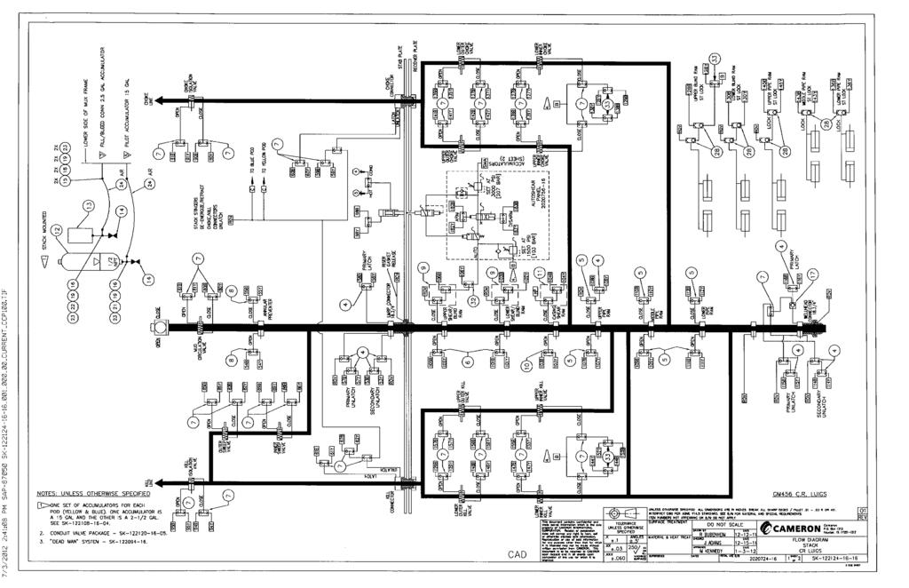
58
Appendix K Appendix K
 Appendix K BOP Leaks There were five minor leaks in the Deepwater Horizon BOP control system: three were identified after the BOP stack was latched to the wellhead in February 2010, and two were identified
Case studies from classes led by Dr. Ron Fulbright, University of South Carolina Upstate. IMPROVED BLOWOUT PREVENTER
 INNOVATIVE ANALYSIS IMPROVED BLOWOUT PREVENTER 1. BRIEF DESCRIPTION OF THE SITUATION The blowout preventer (BOP) is a valve assembly usually mounted on the sea floor at the mouth of an oil well to control
Module No. # 04 Lecture No. # 3.1 Case studies (continued) (Refer Slide Time: 00:10)
 (Refer Slide Time: 00:10)") Health, Safety and Environmental Management in Petroleum and offshore Engineering Prof. Dr. Srinivasan Chandrasekaran Department of Ocean Engineering Indian Institute of Technology, Madras Module No. #
Health, Safety and Environmental Management in Petroleum and offshore Engineering Prof. Dr. Srinivasan Chandrasekaran Department of Ocean Engineering Indian Institute of Technology, Madras Module No. #
Success Paths: A Risk Informed Approach to Oil & Gas Well Control
 API Winter E&P Standards Conference, Austin January 18, 2017 Success Paths: A Risk Informed Approach to Oil & Gas Well Control Dr. Dan Fraser Director, Strategic Alliances for Global Energy Solutions,
The report gives a summary of the background and motivation for the audit activity and summarizes the observations made at the meetings.
 Audit Report AUDIT REPORT (UNOFFICIAL TRANSLATION) AUDIT OF USE OF ANNULAR SAFETY VALVES IN GAS LIFT COMPLETIONS SUMMARY During the period from June 2003 to September 2004, the Petroleum Safety Authority
Marine Technology Society
 Marine Technology Society Dynamic Positioning Conference 21-22 October, 1997 Session I Review of DP Applications, Consequences and Cost of Failures Drilling Fundamentals-DP Operations-Drilling with Riser
Dynamically Positioned (DP) Mobile Offshore Drilling Unit (MODU) Critical Systems, Personnel and Training
 Mobile Offshore Drilling Unit (MODU) Critical Systems, Personnel and Training") Commandant United States Coast Guard 2100 2 nd Street, S.W. STOP 7581 Washington, DC 20593-7581 Staff Symbol: CG-xxx Phone: (202) 372-xxxx Fax: (202) 372-xxx CG-xxx Policy Letter XX-11 From: To: Subj:
Commandant United States Coast Guard 2100 2 nd Street, S.W. STOP 7581 Washington, DC 20593-7581 Staff Symbol: CG-xxx Phone: (202) 372-xxxx Fax: (202) 372-xxx CG-xxx Policy Letter XX-11 From: To: Subj:
IWCF Equipment Sample Questions (Surface Stack)
") IWCF Equipment Sample Questions (Surface Stack) 1. During a well control operation 4000 psi was shut in below the middle pipe rams. Ram type BOP data: Model: Cameron U type Rated Working Pressure: 15000
IWCF Equipment Sample Questions (Surface Stack) 1. During a well control operation 4000 psi was shut in below the middle pipe rams. Ram type BOP data: Model: Cameron U type Rated Working Pressure: 15000
IWCF Equipment Sample Questions (Combination of Surface and Subsea Stack)
") IWCF Equipment Sample Questions (Combination of Surface and Subsea Stack) 1. Given the volumes below, how much hydraulic fluid will be required to carry out the following operations (no safety margin)?
IWCF Equipment Sample Questions (Combination of Surface and Subsea Stack) 1. Given the volumes below, how much hydraulic fluid will be required to carry out the following operations (no safety margin)?
SEMS II: BSEE should focus on eliminating human error
 SEMS II: BSEE should focus on eliminating human error How US companies can prevent accidents on start-ups and shut-downs by using valve interlocks The proposed changes to BSEE s SEMS (Safety and Environmental
API Std 53 - Blowout Prevention Equipment Systems for Drilling Wells Standard Edition Section Inquiry # Question Reply
 API Std - Blowout Prevention Equipment Systems for Drilling Wells Standard Edition Section Inquiry # Question Reply Last update: August 12, 2015 Question 1: In reference to API Standard requirement 4.4.3,
The Developing Design of the Blowout Preventer in Deep Water
 The Developing Design of the Blowout Preventer in Deep Water IADC World Drilling 2011 Conference & Exhibition 15-16 June 2011, Bella Centre, Copenhagen Eric Brown Project Manager National Oilwell Varco
Last Updated: April 19, 2018
 API Std 53 - Blowout Prevention Equipment Systems for Drilling Wells Last Updated: April 19, 2018 Standard Edition Section Inquiry # Question Reply 4.3.6 53-10-17 The cost of NDE/NDT inspection of some
DEPARTMENT OF ENVIRONMENTAL PROTECTION Office of Oil and Gas Management
 DEPARTMENT OF ENVIRONMENTAL PROTECTION Office of Oil and Gas Management DOCUMENT NUMBER: 800-0810-003 TITLE: EFFECTIVE DATE: AUTHORITY: POLICY: PURPOSE: APPLICABILITY: DISCLAIMER: Guidelines for Development
ANNUAL DYNAMIC POSITIONING TRIALS FOR DYNAMICALLY POSITIONED VESSELS
 Author s Name Name of the Paper Session DYNAMIC POSITIONING CONFERENCE October 11-12, 2011 OPERATIONS SESSION ANNUAL DYNAMIC POSITIONING TRIALS FOR DYNAMICALLY POSITIONED VESSELS By Ian Giddings The International
Deepwater Horizon Incident Internal Investigation
 Not all Information has been verified or corroborated. Subject to review based on additional information or analysis. Deepwater Horizon Incident Internal Investigation 1 Areas of Discussion Investigation
API Std 53 - Blowout Prevention Equipment Systems for Drilling Wells
 4.3.6-10-17 API Std - Blowout Prevention Equipment Systems for Drilling Wells The cost of NDE/NDT inspection of some fasteners outweigh the cost to replace with new. Since this is the case, many equipment
International Association of Drilling Contractors North Sea Chapter HPHT Guidance on MODU Safety Case Content
 International Association of Drilling Contractors North Sea Chapter HPHT Guidance on MODU Safety Case Content Contents 1. Abbreviations 2. Background 3. Definition 4. Well Conditions 5. HPHT Safety Case
API Std 53 - Blowout Prevention Equipment Systems for Drilling Wells
 Standard Edition Section Inquiry # Question Reply 4.3.6-10-17 API Std - Blowout Prevention Equipment Systems for Drilling Wells The cost of NDE/NDT inspection of some fasteners outweigh the cost to replace
Safety and Risk Engineering. HSE Case Implementation Clive Rawson
 Safety and Risk Engineering HSE Case Implementation Clive Rawson Purpose ALARP Risk Assessment Major Accident Events Bowties Safety Critical Systems Performance Standards Implementation Getting HSE Case
The topics I will briefly cover, are; Stack Configurations Wellhead Connector Considerations Control Systems Tensioning Systems will be discussed by
 Thank you Greg. 1 The topics I will briefly cover, are; Stack Configurations Wellhead Connector Considerations Control Systems Tensioning Systems will be discussed by Mr. Muhammad Sadiq, however in short,
ENGINEERING + SERVICES INSPECTION, MAINTENANCE + RECERTIFICATION (IMR)
") ENGINEERING + SERVICES INSPECTION, MAINTENANCE + RECERTIFICATION (IMR) 7 STEPS TO HOSE VALUE AND REGULATORY COMPLIANCE Periodic inspection and testing of flexible hose assemblies is an essential component
ENGINEERING + SERVICES INSPECTION, MAINTENANCE + RECERTIFICATION (IMR) 7 STEPS TO HOSE VALUE AND REGULATORY COMPLIANCE Periodic inspection and testing of flexible hose assemblies is an essential component
Entry Level Requirements and Basic Introductory Course Outline for New Remotely Operated Vehicle (ROV) Personnel
 Personnel") AB Entry Level Requirements and Basic Introductory Course Outline for New Remotely Operated Vehicle (ROV) Personnel International Marine Contractors Association www.imca-int.com IMCA R 002 Rev. 2 May 2009
AB Entry Level Requirements and Basic Introductory Course Outline for New Remotely Operated Vehicle (ROV) Personnel International Marine Contractors Association www.imca-int.com IMCA R 002 Rev. 2 May 2009
Subsea Safety Systems
 Subsea Safety Systems The ELSA-HP has been developed to service the high pressure horizontal tree completion and intervention market. With systems designed and qualified up to 15,000 psi, 250 degf and
Pressure Equipment Directive PED 2014/68/EU Commission's Working Group "Pressure"
 H. INTERPRETATION OF OTHER ESSENTIAL SAFETY REQUIREMENTS Guideline H-02 Guideline related to: Annex I Section 3.2.2 and 7.4 Final assessment (Annex I Section 3.2.2) of pressure equipment must include a
Best Practices - Coiled Tubing Deployed Ball Drop Type Perforating Firing Systems
 Best Practices - Coiled Tubing Deployed Ball Drop Type Perforating Firing Systems As a result of a recent job incident utilizing a Ball Drop Type firing system deployed on coiled tubing, the following
REDUNDANT PROPULSION SHIPS RULES FOR CLASSIFICATION OF NEWBUILDINGS DET NORSKE VERITAS SPECIAL EQUIPMENT AND SYSTEMS ADDITIONAL CLASS PART 6 CHAPTER 2
 RULES FOR CLASSIFICATION OF SHIPS NEWBUILDINGS SPECIAL EQUIPMENT AND SYSTEMS ADDITIONAL CLASS PART 6 CHAPTER 2 REDUNDANT PROPULSION JANUARY 1996 CONTENTS PAGE Sec. 1 General Requirements... 5 Sec. 2 System
SLOP RECEPTION AND PROCESSING FACILITIES
 RULES FOR CLASSIFICATION OF SHIPS NEWBUILDINGS SPECIAL SERVICE AND TYPE ADDITIONAL CLASS PART 5 CHAPTER 8 SLOP RECEPTION AND PROCESSING FACILITIES JANUARY 2011 CONTENTS PAGE Sec. 1 General Requirements...
DRILLING HOSE SOLUTIONS
 DRILLING HOSE SOLUTIONS HIGH PRESSURE FLEXIBLE LINES FOR A WIDE RANGE OF DRILLING APPLICATIONS HIGH QUALITY - HIGH STANDARD WE DELIVER ACCORDING TO THE HIGHEST LEVELS OF SPECIFICATIONS AND STANDARDS WITH
CHE Well Testing Package/Service:
 CHE Well Testing Package/Service: CHE delivers well testing package And services, trailer mounted well testing package and offshore/onshore well testing services with over 10 years experience. Our testing
Best Practice RBI Technology Process by SVT-PP SIMTECH
 Best Practice RBI Technology Process by SVT-PP SIMTECH We define the best practice in RBI as a proactive technology process which is used to formally and reliably optimise the inspection efforts for each
Guide for Evaluating Your Hose Assembly Supplier
 Guide for Evaluating Your Hose Assembly Supplier Supplier Evaluation Checklist, and How to Clearly Define Application Requirements Safe, reliable hose assemblies require appropriate specification work
A practical solution for managing risk during locked to bottom operations
 SUPER BAILS: A practical solution for managing risk during locked to bottom operations Henry Bromfield, Jon Wright & David Cree. September 2017. 1 ABSTRACT The following paper presents a new and practical
Learn more at
 IBP1833_06 COST EFFICIENT ARTIFICIAL BUOYANT SEABED DRILLING SOLUTION Dan Moutrey 1, Frank Lim 2 Copyright 2006, Instituto Brasileiro de Petróleo e Gás - IBP This Technical Paper was prepared for presentation
INTERPRETATION NOTE ISSUED UNDER THE PETROLEUM DRILLING REGULATIONS (CNR 1150/96)
") BOP CLASSIFICATION SYSTEM FOR ONSHORE NEWFOUNDLAND AND LABRADOR INTERPRETATION NOTE ISSUED UNDER THE PETROLEUM DRILLING REGULATIONS (CNR 1150/96) PREPARED BY THE PETROLEUM RESOURCE DEVELOPMENT DIVISION
BOP CLASSIFICATION SYSTEM FOR ONSHORE NEWFOUNDLAND AND LABRADOR INTERPRETATION NOTE ISSUED UNDER THE PETROLEUM DRILLING REGULATIONS (CNR 1150/96) PREPARED BY THE PETROLEUM RESOURCE DEVELOPMENT DIVISION
NORSOK STANDARD D-002 Edition 2 (2013)
") Date: 2015-06-01 NORSOK STANDARD D-002 Edition 2 (2013) Well intervention equipment Frequently asked questions - FAQ NORSOK 2015 2 INTRODUCTION NORSOK standard D-002 Revision 2 was released in June 2013.
Date: 2015-06-01 NORSOK STANDARD D-002 Edition 2 (2013) Well intervention equipment Frequently asked questions - FAQ NORSOK 2015 2 INTRODUCTION NORSOK standard D-002 Revision 2 was released in June 2013.
LNG TANDEM OFFLOADING A KEY ENABLING TECHNOLOGY TO MAKE LNG PRODUCTION OFFSHORE HAPPEN
 LNG TANDEM OFFLOADING A KEY ENABLING TECHNOLOGY TO MAKE LNG PRODUCTION OFFSHORE HAPPEN Fabrice Dumortier 1, Jean-Pierre Queau 1, Jean-Robert Fournier 2 1. SBM Offshore 2. SBM Offshore Keywords: 1. LNG;
Protecting People and the Environment during Stimulation Treatments in Offshore Settings
 Protecting People and the Environment during Stimulation Treatments in Offshore Settings NASEM Workshop: Offshore Well Completion and Stimulation using Hydraulic Fracturing and Other Technologies Paul
Assessment of Ships and Managers for the Acceptance of Extended Interval Between Bottom Surveys in Dry-Dock
 CLASSIFICATION NOTES No. 72.2 Assessment of Ships and Managers for the Acceptance of Extended Interval Between Bottom Surveys in Dry-Dock MAY 2012 The electronic pdf version of this document found through
Pressure Equipment Directive PED 2014/68/EU Commission's Working Group "Pressure"
 I. MISCELLANEOUS Guideline I-01 Guideline related to: Article 4 paragraph 3 What is to be understood by "sound engineering practice"? Sound engineering practice means, without prejudice to Article 5, paragraph
AUSTRALIA ARGENTINA CANADA EGYPT NORTH SEA U.S. CENTRAL U.S. GULF. SEMS HAZARD ANALYSIS TRAINING September 29, 2011
 AUSTRALIA ARGENTINA CANADA EGYPT NORTH SEA U.S. CENTRAL U.S. GULF SEMS HAZARD ANALYSIS TRAINING September 29, 2011 Purpose The purpose of this meeting is to provide guidelines for determination of hazard
1. UPDATE 12/12/2014: What wells are regulated under the MIA Program? Must they be drilled, stimulated, and completed? Must they be in production?
 PLEASE NOTE THAT ALL USES OF THE WORD OPERATOR IN THIS DOCUMENT REFER TO THE ACT 13 DEFINITION OF WELL OPERATOR AND THUS, REFERENCE THE PERMIT HOLDER (PERMITEE) FOR THE WELL. ANY ENFORCEMENT ACTIONS UNDER
Purpose. Scope. Process flow OPERATING PROCEDURE 07: HAZARD LOG MANAGEMENT
 SYDNEY TRAINS SAFETY MANAGEMENT SYSTEM OPERATING PROCEDURE 07: HAZARD LOG MANAGEMENT Purpose Scope Process flow This operating procedure supports SMS-07-SP-3067 Manage Safety Change and establishes the
2/15/06 Nora Ghobrial
 Deepwater Gas Lift: Issues and Considerations when Gas Lifting in a Deepwater Environment 2/15/06 Nora Ghobrial Shell recently started it s 1st Deepwater Gas Lift on the Ram/Powell TLP Deepwater Gas Lift:
DEPARTMENT OF ENVIRONMENTAL PROTECTION Office of Oil and Gas Management
 DEPARTMENT OF ENVIRONMENTAL PROTECTION Office of Oil and Gas Management DOCUMENT NUMBER: 800-0810-003 TITLE: EFFECTIVE DATE: AUTHORITY: POLICY: PURPOSE: APPLICABILITY: DISCLAIMER: Guidelines for Development
Valve Replacement: Using Non-Intrusive Isolation Technology to Minimize Production Downtime
 CASE STUDY CS15-02 >> Valve Replacement: Using Non-Intrusive Isolation Technology to Minimize Production Downtime What s Inside:» Explore Double Block & Monitor» Increase Operational Safety» Achieve Double
Subsea Wellhead and Conductor Fatigue
 Subsea Wellhead and Conductor Fatigue 29th January 2014 Simeon Powell, PE Importance of Wellhead Fatigue Fatigue failure of high pressure wellhead housing Due to VIV West of Shetland Region 440 meter water
Well Control Drill Guide Example Only. Drill Guide is the list of drills, questions and attributes that are in DrillPad.
 Well Control Drill Guide Example Only Drill Guide is the list of drills, questions and attributes that are in DrillPad. This Well Control Drill Guide will be used in conjunction with the rig-specific well
RPSEA UDW Forum June 22 & 23, Secure Energy for America
 RPSEA UDW Forum June 22 & 23, 2010 Secure Energy for America PROJECT TEAM RPSEA Operator Advisory Committee Anadarko Chevron Shell ConocoPhillips Subcontractors IntecSea NOV CTES General Marine Contractors
OFFSHORE. Trasfor OFFSHORE
 OFFSHORE Trasfor OFFSHORE 2 Trasfor I Offshore Introduction Trasfor s transformers for offshore applications ensure the highest performance level of reliability in any working condition. More than 40 skilled
Completion Workover Riser System. Enabling efficient operations by reducing interface complexities and minimizes operational risk
 Completion Workover Riser System Enabling efficient operations by reducing interface complexities and minimizes operational risk Well integrity with fatigue management were key drivers for our system design
The Best Use of Lockout/Tagout and Control Reliable Circuits
 Session No. 565 The Best Use of Lockout/Tagout and Control Reliable Circuits Introduction L. Tyson Ross, P.E., C.S.P. Principal LJB Inc. Dayton, Ohio Anyone involved in the design, installation, operation,
A REAL-TIME RISK-INFORMED BOP RETRIEVAL DECISION TOOL
 A REAL-TIME RISK-INFORMED BOP RETRIEVAL DECISION TOOL Luiz Fernando Oliveira 1, Joaquim D. Amaral Netto 1, and Gean Rocha 1 1 DNV GL: Rua Sete de Setembro 111,12 andar, Rio de Janeiro, RJ, 20050-006,Brazil
RAMSTM. 360 Riser and Anchor-Chain Integrity Monitoring for FPSOs
 RAMS 360 Riser and Anchor-Chain Integrity Monitoring for FPSOs Introduction to RAMS Tritech s RAMS is a 360 anchor-chain and riser integrity monitoring system for Floating Production Storage and Offloading
En-Tegrity. A step change in subsea well control safety
 En-Tegrity A step change in subsea well control safety Product Overview 7-3/8, 10,000psi, Shear & Seal Gate Valve Main Well Barrier in Intervention Well Control Package (WCP) Features Bi-Directional Sealing
NORSOK STANDARD SYSTEM REQUIREMENTS BOP, DIVERTER AND DRILLING RISER SYSTEM (SYSTEM NO.: 12-30, 12-40)
") NORSOK STANDARD SYSTEM REQUIREMENTS BOP, DIVERTER AND DRILLING RISER SYSTEM (SYSTEM NO.: 12-30, 12-40) Rev.1, Dec. 1994 CONTENTS 1 FOREWORD 2 2 SCOPE 2 3 NORMATIVE REFERENCES 2 4 DEFINITIONS AND ABBREVIATIONS
NORSOK STANDARD SYSTEM REQUIREMENTS BOP, DIVERTER AND DRILLING RISER SYSTEM (SYSTEM NO.: 12-30, 12-40) Rev.1, Dec. 1994 CONTENTS 1 FOREWORD 2 2 SCOPE 2 3 NORMATIVE REFERENCES 2 4 DEFINITIONS AND ABBREVIATIONS
Development of a Subsurface Mudline Packer to Reduce Risk of Flow after Cementing and Sustained Casing Pressure, While Providing a Platform for P&A.
 Development of a Subsurface Mudline Packer to Reduce Risk of Flow after Cementing and Sustained Casing Pressure, While Providing a Platform for P&A. Sean Yakeley, Ed Wood and Yang Xu (Baker Hughes Inc)
CODE OF PRACTICE 42 IMPLEMENTATION OF EIGA CARBON DIOXIDE STANDARDS REVISION 2: 2018
 CODE OF PRACTICE 42 IMPLEMENTATION OF EIGA CARBON DIOXIDE STANDARDS REVISION 2: 2018 CODE OF PRACTICE 42 IMPLEMENTATION OF EIGA CARBON DIOXIDE STANDARDS REVISION 2: 2018 Copyright 2018 by British Compressed
Managing Dynamic Positioning (DP) Operations
 Operations") Managing Dynamic Positioning (DP) Operations Captain Andy Goldsmith, IMCA Technical Adviser IOSH Offshore Conference Tools for the trade 19 October 2017 1 2 IMCA OPERATIONAL STRUCTURE BOARD CEO SECRETARIAT
Managing Dynamic Positioning (DP) Operations Captain Andy Goldsmith, IMCA Technical Adviser IOSH Offshore Conference Tools for the trade 19 October 2017 1 2 IMCA OPERATIONAL STRUCTURE BOARD CEO SECRETARIAT
Offshore Managed Pressure Drilling Experiences in Asia Pacific. SPE paper
 Offshore Managed Pressure Drilling Experiences in Asia Pacific SPE paper 119875 Authors: Steve Nas, Shaun Toralde, Chad Wuest, SPE, Weatherford Solutions Sdn Bhd, SPE, Weatherford Indonesia SPE, Weatherford
A study on the relation between safety analysis process and system engineering process of train control system
 A study on the relation between safety analysis process and system engineering process of train control system Abstract - In this paper, the relationship between system engineering lifecycle and safety
Is my well safe? Terje Løkke-Sørensen, CTO, add energy
 Is my well safe? Terje Løkke-Sørensen, CTO, add energy Introduction What is? a Safe Well?.. an Unsafe Well? A well with 2 well barriers both fully intact? A well with known issues risks can be managed?
Significant Change to Dairy Heat Treatment Equipment and Systems
 Significant to Dairy Heat Treatment September 2008 Page 1 Significant to Dairy Heat Treatment Equipment and Systems September 2008 1 Background Requirements for the assessment of dairy heat treatment equipment
Talk 2 Tree & Wellhead Valve Testing Leak Rate Acceptance. Talk 3 DHSV Control Line hydrocarbon Ingress measurement & acceptability
 Talisman energy COIN Virtual Meeting # 17 26 th January 2011 Darren Bewick Graeme Douglas Martin Forbes David McGuckien Matt Morrison Martin Mosley Talisman Energy UK Ltd (TLMUK), Aberdeen 1 Presentations
Risk-Based Process Safety for Upstream Oil & Gas: Put Your Boots on It s Coming! Mark Hansen and Jim Johnstone
 1. They did not attack the fuel storage Risk-Based Process Safety for Upstream Oil & Gas: Put Your Boots on It s Coming! Mark Hansen and Jim Johnstone Slide 2 Why is there Concern About Process Safety?
RULES OF THE OIL AND GAS PROGRAM DIVISION OF WATER RESOURCES CHAPTER DRILLING WELLS TABLE OF CONTENTS
 RULES OF THE OIL AND GAS PROGRAM DIVISION OF WATER RESOURCES CHAPTER 0400-52-06 DRILLING WELLS TABLE OF CONTENTS 0400-52-06-.01 Drilling Equipment 0400-52-06-.03 Casingheads 0400-52-06-.02 Blowout Prevention
IMCA Competence Assessment Portfolio June 2013
 IMCA Competence Portfolio June 2013 Name: Start Date in Current Self- Checklist Entry Level Criteria Acceptance Criteria Attained Certification 500 GRT or more: Valid certificate of competency or certificate
Subj: USE OF DYNAMIC POSITIONING (DP) BY OFFSHORE SUPPLY VESSELS (OSVs) FOR OIL AND HAZMAT TRANSFERS
 BY OFFSHORE SUPPLY VESSELS (OSVs) FOR OIL AND HAZMAT TRANSFERS") Commander 501 Magazine Street Eighth Coast Guard District New Orleans, LA 70130-3396 Hale Boggs Federal Bldg. Staff Symbol: (mvs) Phone: (504) 589-6271 FAX: (504) 589-4999 MEMORANDUM 16711/DP OSVs D8(m)
Commander 501 Magazine Street Eighth Coast Guard District New Orleans, LA 70130-3396 Hale Boggs Federal Bldg. Staff Symbol: (mvs) Phone: (504) 589-6271 FAX: (504) 589-4999 MEMORANDUM 16711/DP OSVs D8(m)
IMPLEMENTATION OF EIGA CARBON DIOXIDE STANDARDS
 CODE OF PRACTICE 42 IMPLEMENTATION OF EIGA CARBON DIOXIDE STANDARDS REVISION 1 : 2014 CODE OF PRACTICE 42 IMPLEMENTATION OF EIGA CARBON DIOXIDE STANDARDS REVISION 1: 2014 Copyright 2014 by British Compressed
IMCA Competence Assessment Portfolio June 2013
 IMCA Competence Portfolio June 2013 Name: Start Date in Current Self- Checklist Entry Level Criteria Acceptance Criteria Attained Certification 500 GRT or more: Valid certificate of competency or certificate
Isolation and Lockout
 Work Procedure Facilities Management UBCO-RMS-OHS-WP 16-001 Date Created: July 13, 1999 Date Updated: April 4, 2016 Supersedes: September 18, 2003 1. SCOPE Isolation and Lockout This procedure establishes
MAINTENANCE AND SAFETY OF CNG REFUELLING STATIONS
 ISSN 1172-3416 NZ GCP 2 : 1993 NEW ZEALAND GAS CODE OF PRACTICE for MAINTENANCE AND SAFETY OF CNG REFUELLING STATIONS Issued by the Secretary of Commerce in accordance with the Gas Act 1992 THE GAS ACT
IMCA Update 2018 Adding value to DP operations
 IMCA Update 2018 Adding value to DP operations Captain Mike Meade, M3 Marine, CEO & Director Captain Andy Goldsmith, IMCA Technical Adviser 8 th DP Asia Conference 28 June 2018 CONNECTION WITH THE DP INDUSTRY
APPENDIX A1 - Drilling and completion work programme
 APPENDIX A1 - Drilling and completion work programme Information about the well and drilling To the extent possible, the international system of units (SI) should be adhered to, and the drilling programme
Procedure: Pressure equipment safety
 Procedure: Pressure equipment safety Purpose The purpose of this procedure is to define the method for safe operation and inspection of pressure equipment and the collection and recording of associated
Chapter 4 Key Findings. 4 Key Findings
 Chapter 4 Key Findings 211 4 Key Findings 212 Chapter 4 Key Findings This summarizes the key findings of the investigation team based on its extensive review of available information concerning the Macondo
Good Morning everyone, I will be talking this morning about the review and restructure of Cruise Whitsundays Safety Management Systems.
 Good Morning everyone, I will be talking this morning about the review and restructure of Cruise Whitsundays Safety Management Systems. 1 This presentation is about the restructure of Cruise Whitsundays
Every things under control High-Integrity Pressure Protection System (HIPPS)
") Every things under control www.adico.co info@adico.co Table Of Contents 1. Introduction... 2 2. Standards... 3 3. HIPPS vs Emergency Shut Down... 4 4. Safety Requirement Specification... 4 5. Device Integrity
Every things under control www.adico.co info@adico.co Table Of Contents 1. Introduction... 2 2. Standards... 3 3. HIPPS vs Emergency Shut Down... 4 4. Safety Requirement Specification... 4 5. Device Integrity
Lockout/Tagout Training Overview. Safety Fest 2013
 Lockout/Tagout Training Overview Safety Fest 2013 Purpose of Lockout/Tagout The standard covers the servicing and maintenance of machine and equipment in which the unexpected energization or start up of
MEDICAL GAS CYLINDERS AND MEDICAL PIPELINE SYSTEMS (MGPS) POLICY
 POLICY") MEDICAL GAS CYLINDERS AND MEDICAL PIPELINE SYSTEMS (MGPS) POLICY Version: 4 Date issued: April 2018 Review date: April 2021 Applies to: All staff (excluding office and clerical staff) This document is
MEDICAL GAS CYLINDERS AND MEDICAL PIPELINE SYSTEMS (MGPS) POLICY Version: 4 Date issued: April 2018 Review date: April 2021 Applies to: All staff (excluding office and clerical staff) This document is
TRI LOK SAFETY MANUAL TRI LOK TRIPLE OFFSET BUTTERFLY VALVE. The High Performance Company
 TRI LOK TRI LOK TRIPLE OFFSET BUTTERFLY VALVE SAFETY MANUAL The High Performance Company Table of Contents 1.0 Introduction...1 1.1 Terms and Abbreviations... 1 1.2 Acronyms... 1 1.3 Product Support...
Section J. How to develop safety elements for project safety management system. How to develop safety elements for project SMS
 Section J How to develop safety elements for project safety management system 1. Once the project management has developed or adopted a safety policy, it needs to develop safety elements to meet the objectives
Operations and Requirements A Practical Approach to Managing DP Operations
 Operations and Requirements A Practical Approach to Managing DP Operations Suman Muddusetti Shell International Exploration and Production, Inc. Doug Phillips Global Maritime, Inc. October 17-18, 2006
SIL Safety Manual. ULTRAMAT 6 Gas Analyzer for the Determination of IR-Absorbing Gases. Supplement to instruction manual ULTRAMAT 6 and OXYMAT 6
 ULTRAMAT 6 Gas Analyzer for the Determination of IR-Absorbing Gases SIL Safety Manual Supplement to instruction manual ULTRAMAT 6 and OXYMAT 6 ULTRAMAT 6F 7MB2111, 7MB2117, 7MB2112, 7MB2118 ULTRAMAT 6E
T e l N o : F a x N o : E m a i l : a i s h c m c - m e. c o m w w w. c m c - m e.
 MU047: Practical Valve Technology: Selection, Installation, Upgrading, Inspection & Troubleshooting MU047 Rev.002 CMCT COURSE OUTLINE Page 1 of 7 Training Description: This five-day intensive course covers
Deepwater Horizon, by Metin Çakanyıldırım and references cited therein.
 Deepwater Horizon Page 1 Outline Summary of the events and companies Technical problems and their association with companies Managerial problems Risk averse vs. risk seeking tendencies Suggestions to avoid
1.0 PURPOSE 2.0 SCOPE 3.0 DEFINITIONS. ANSI: American National Standards Institute. CCC: Chemical Control Centre
 Revision Date: 5/17/2016 Page: 1 of 13 Health & Safety has developed the emergency eyewash & safety shower equipment procedure which will be implemented in 3 phases over the next four years. Phase 1 will
Development of Self-Installing Deepwater Spar. Ashit Jadav February 2017
 Development of Self-Installing Deepwater Spar Ashit Jadav February 2017 Contents Introduction & Background ACE Spar breakdown Installation Sequence Main particulars, Hull design and Weight control Stability
III Code. TRACECA Maritime Safety and Security IMSAS workshop Kiev (Ukraine) III Code. Dr. Jens U. Schröder-Hinrichs
 III Code. Dr. Jens U. Schröder-Hinrichs") III Code III Code III Code TRACECA Maritime Safety and Security IMSAS workshop Kiev (Ukraine) Dr. Jens U. Schröder-Hinrichs IMSAS workshop Kiev Agenda 1 2 3 4 5 6 7 8 9 Introduction Background to IMSAS
III Code III Code III Code TRACECA Maritime Safety and Security IMSAS workshop Kiev (Ukraine) Dr. Jens U. Schröder-Hinrichs IMSAS workshop Kiev Agenda 1 2 3 4 5 6 7 8 9 Introduction Background to IMSAS
New Thinking in Control Reliability
 Doug Nix, A.Sc.T. Compliance InSight Consulting Inc. New Thinking in Control Reliability Or Your Next Big Headache www.machinerysafety101.com (519) 729-5704 Control Reliability Burning Questions from the
Standard Pneumatic Test Procedure Requirements for Piping Systems
 the pressure equipment safety authority Standard Pneumatic Test Procedure Requirements for Piping Systems AB-522 Edition 2, Rev. 1 Issued 2016-10-24 Table of Contents FOREWORD... 1 1.0 INTRODUCTION...
MINE SAFETY TARGETED ASSESSMENT PROGRAM. Ground or strata failure NSW metalliferous mines. April
 MINE SAFETY TARGETED ASSESSMENT PROGRAM Ground or strata failure NSW metalliferous mines April 2017 www.resourcesandenergy.nsw.gov.au Document control Publication title: Ground or strata failure NSW metalliferous
OIL POLLUTION IN THE ARCTIC - RISKS AND MITIGATING MEASURES
 Proceedings of the ASME 2011 30th International Conference on Ocean, Offshore and Arctic Engineering OMAE2011 June 19-24, 2011, Rotterdam, The Netherlands OMAE2011-49157 OIL POLLUTION IN THE ARCTIC - RISKS
GUIDE YVL 3.7 / 26 Se p t e m b e r 2008
 GUIDE YVL 3.7 / 26 Se p t e m b e r 2008 Pressure equipment of nuclear facilities Commissioning inspection 1 Ge n e r a l 3 2 Contents of the commissioning inspection 3 3 First phase of the commissioning
RIGID RISERS FOR TANKER FPSOs
 RIGID RISERS FOR TANKER FPSOs Stephen A. Hatton 2H Offshore Engineering Ltd. SUMMARY Recent development work on the subject of dynamic rigid (steel pipe) risers demonstrates that their scope of application
Technical Standards and Legislation: Risk Based Inspection. Presenter: Pierre Swart
 Technical Standards and Legislation: Risk Based Inspection Presenter: Pierre Swart Agenda Change in Legislation. Where RBI fits in. Application to implement RBI. RBI concepts. Elements of an RBI analysis.
DeZURIK. KSV Knife Gate Valve. Safety Manual
 KSV Knife Gate Valve Safety Manual Manual D11035 August 29, 2014 Table of Contents 1 Introduction... 3 1.1 Terms... 3 1.2 Abbreviations... 4 1.3 Product Support... 4 1.4 Related Literature... 4 1.5 Reference
Dynamic Positioning: Method for Disaster Prevention and Risk Management
 Available online at www.sciencedirect.com ScienceDirect Procedia Earth and Planetary Science 11 ( 2015 ) 216 223 Global Challenges, Policy Framework & Sustainable Development for Mining of Mineral and
Grantek Systems Integration
 Grantek Systems Integration Understanding Machine Safeguarding and Lockout/Tagout October 18 th 2017 Jeff Winter, CSP, FS Eng. Director, Safety Practice Today s Speaker: Jeff Winter BIO: TUV Certified
International Well Control Forum. Well Intervention Pressure Control Level 2 Syllabus July 2015 Version 7.0
 International Well Control Forum Well Intervention Pressure Control Level Syllabus July 01 Version 7.0 Well Intervention Pressure Control Syllabus - Level Contents Guidance Notes... 1. OVERVIEW... 1.1.