CONTENTS DESCRIPTION INTENDED USE. WARNINGS & NOTES. PRECAUTIONS. INSTALLATION & SET-UP (Including battery charging & powering up)
|
|
|
- Brice Hodge
- 6 years ago
- Views:
Transcription
1
2 NO CONTENTS DESCRIPTION PAGE BODYGUARD PUMP OVERVIEW PUMP DESCRIPTION AND FUNCTIONS SYSTEM SAFETY CHECKS SYMBOLS INTENDED USE. WARNINGS & NOTES. PRECAUTIONS INSTALLATION & SET-UP (Including battery charging & powering up) OPERATING THE BODYGUARD AMBULATORY PUMP Security: Access Codes & Keypad Lock Setting Up & Modifying Protocols Administration Sets Loading the Administration Set Powering Up & Priming a Set Selecting a Protocol Interpreting Display Screen Whilst Infusing Rate Change during Delivery (Rate Titration) Bolus Dose Delivery: Patient Controlled/Clinician Activated End of Infusion & Bag Change Using History Functions: Current Patient & 512 Event log Eliminating Air during Operation Alarms, Alerts & Troubleshooting Review Pump Set Up Change Pump Set Up Keep Vein Open (KVO) MAINTENANCE & SERVICE APPENDICES INDEX
 plus patient controlled bolus (PCEA) - Continuous only (Epidural Analgesia (EA))- infuse 0.1-1000ml @ 0.")
")
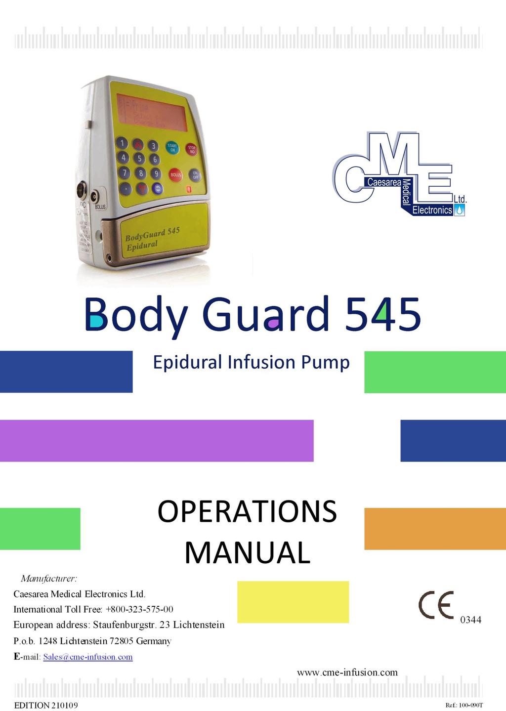
3 1.0 BODYGUARD PUMP OVERVIEW The BodyGuard Epidural System provides the following : Multiple programmes: - Bolus only (Patient Controlled) ml/h - Continuous (basal) plus patient controlled bolus (PCEA) - Continuous only (Epidural Analgesia (EA))- infuse ml/h Used for ambulatory care, can be pole mounted or used with a carrying pouch A small, light & compact pump with quiet operation +/- 5% accuracy, even at low infusion rates Rechargeable Li-Polymer internal battery & mains operations Battery charged in a pole mount charging cradle or with an A/C adaptor Free-flow protection integral to all administration sets (anti-siphon/reflux) Prevents false occlusion alarms when delivering boluses through an epidural catheter by automatically varying bolus delivery rate Post-Occlusion Bolus Prevention System MediGuard protection ensures protocol is appropriate to patients weight 512 Event Log plus detailed patient history (1024 events log is optional) Ability to output history to PC (printer or file) using BodyComm software (optional) 3

4 2.0 PUMP DESCRIPTION AND FUNCTIONS FRONT OF BODYGUARD AMBULATORY INFUSION PUMP DISPLAY SCREEN a. Displays pump/infusion status b. Displays programming choices & instructions 2. UP ARROW a. Scrolls up through options on menu screens 3. START/OK a. Confirms parameter selection b. Starts infusion 4. STOP/NO a. Stops infusion/bolus b. Silences an alarm condition c. Stops priming d. Zeroes the displayed value during programming e. Erases the last digit during programming f. Returns to previous screen. g. Returns to main menu when held down for 2 seconds after stopping infusion delivery 5. BOLUS a. Administers bolus dose during PCA regimes (this function is normally performed using the remote bolus cable) b. Activates clinician (CA) bolus when pump in STOP mode. (Can only be activated under code conditions) 4
5 6. POWER ON/OFF a. Turns the pump on by pressing and holding the key until the software version confirmation screen appears and a beep is heard b. Turns the system off by pressing and holding the key until the graph is black and a beep is generated 7. LED window (beneath the bolus and on/off keys) a. Green Indicator - Lights during system self-test - Intermittent green light indicates infusion delivery b. Red Indicator - Indicates an alarm state with a continuous red light - Lights when the pump is in a stand-by mode during programming 8. INFO a. When pressed during infusion displays: - Infused Volume & Total to be Infused - Battery Status - Bolus Attempts, Given & Clinician Bolus volume - Protocol review screen - Date & Time b. Press and then to access: - Volume & boluses given in the last 24 hours - Hour-by-hour utilisation data - Hour-by-hour chart of bolus demand in last 24 hours - Hour-by-hour chart of volume infused in last 24 hours c. Holding the key down whilst the pump is infusing (until the graph displayed turns black), locks and unlocks the keypad to prevent accidental or deliberate changes to pump operation. 9. DOWN ARROW: a. Scrolls down through options on menu screens 10. NUMERICAL KEYS: a. Enters numeric parameters during programming 5
 Keyway Pressing Plate Pump door Air sensor - front Air sensor- door Flow Direction Function Opens the door & holds it closed when latch")

6 BODYGUARD PUMP WITH DOOR OPEN No Area Door latch Pressure sensor (behind keyway) Keyway Pressing Plate Pump door Air sensor - front Air sensor- door Flow Direction Function Opens the door & holds it closed when latch is in vertical position Detects downstream tubing restriction and occlusion Alarm level adjustable to suit patient/infusion type. Guides the administration set into correct position and ensures only dedicated administration sets are used Connected to the door by two springs Covers the pressing plate Ultrasonic air detector mounted on the front housing. Mounted on the door Shows direction of fluid flow BODYGUARD PUMP IN CHARGING UNIT Charger display Displays major pump messages & operation values Release handle Push to release the pump from the charging unit 6
7 3.0 SYSTEM SAFETY CHECKS The following details outline the safety checks designed into the BodyGuard pump to minimise the possibility of under or over infusions. FREE FLOW PROTECTION When the set is installed in the pump and the door closed, two ridges on the door clamp the set so only the movement of the motor pistons can allow fluid to pass. With the door open, protection is afforded by a check valve, present in all BodyGuard sets, that prevents free flow towards the patient when the set is not attached to the pump. When the pump is attached to the set and delivering fluid, the pressure delivered by the pump opens the valve. The check valve also prevents reflux. The design of the check valve means that although a pressure of 2-3psi can open the check valve in the direction of the patient reflux cannot occur regardless of the pressure that builds up in the set. POST OCCLUSION BOLUS REDUCTION SYSTEM During an occlusion, pressure in the downstream section of the line can build up to 21psi (depending on user defined settings). When the pump alarms the user will check the line and attempt to clear the occlusion. In the absence of Post Occlusion Bolus Reduction System the pressure build up could cause a surge of fluid into the patient. This feature works by reversing the operation of the motor until pressure in the downstream line is returned to neutral (usually within 15 seconds). AIR-IN-LINE DETECTION BodyGuard utilises two modalities to detect air-in-line. The ultrasonic detector can be configured between 0.0 (OFF) & 1.0ml on the BodyGuard 545 pump for single bubble detection whilst a cumulative check triggers the alarm if an accumulation of smaller bubbles totals 1.0ml (non-configurable) in any 15 minute period. Although a single bubble may not exceed the user defined threshold (e.g. 0.5ml) if the cumulative volume of smaller bubbles exceeds 1ml (e.g. if three 0.4ml bubbles pass the sensor within a 15 minute period) an Air/Up Occlusion alarm is activated. This accumulation feature is particularly useful when infusing products that create a significant number of small air bubbles (out-gas) to a patient who is highly sensitive to air, i.e. infants, neonates, children. If off (0.0ml) there is a 3ml volume for air in line detection. PROGRAMME LIMITS (including MediGuard toxicity settings) Under Change Set Up users can choose from a number of options to limit protocol parameters and set safe ceilings on drugs infused. When the MediGuard feature is on users are asked to set the patients weight (kg) and a toxicity ceiling in either ml, mg or mcg (depending on pump configuration) per kilogram bodyweight per hour. If users try to set a protocol where the component elements (basal rate and boluses) exceeds the MediGuard limit the pump will alert the user to this and request they re-confirm their intentions, amend or revise the toxicity ceiling. Level One users will not be able to change the protocol or ceiling under Select Protocol and will have to select an alternative appropriate protocol or consult senior clinical staff with Level Three authority. Alternatively you can choose to simply limit either the rate or number of boluses delivered over either a 0, 1, 4, or 24 hour period according to local practice. 7


8 4.0 SYMBOLS SYMBOLS & LABELS The following symbols are used on the BodyGuard pump, accessories and consumables. Labels on the pump or statements in this manual preceded by any of the following words and/or symbols are of special significance, intended to help you to operate the pump in a safe and successful manner. Attention, consult accompanying Instructions 0344 CE mark indicates conformance to Medical Device Directive 93/42/EEC Do not dispose of in municipal waste. Symbol indicates separate collection for electrical and electronic equipment. (WEEE Directive 2002/96/EEC). NOTE: Does not apply to the battery. Do not dispose of battery in municipal waste. Symbol indicates separate collection for battery is required. The use of single-use disposable components on more than one patient is a biological hazard. Do not reuse single-use disposable components. Type CF applied part Date of Manufacture Serial Number Expiry Date of disposable LOT Lot Number STERILE EO Sterilized with Ethylene Oxide 8
9 5.0 INTENDED USE. WARNINGS & NOTES. OPERATING PRECAUTIONS INTENDED USE The BodyGuard 545 Epidural Infusion System is intended to be used only for administration via the epidural or intrathecal route (collectively referred to as neuraxial). BodyGuard 545 fully complies with the recommendations of the NHS National Patient Safety Agency (NPSA) that colour-coded epidural administration sets & dedicated epidural pumps should be used for application via this route so as to clearly distinguish them from equipment used for delivery via other routes (e.g. I.V.) To minimize risk when administering neuraxial infusions the BodyGuard 545 Infusion pump & the dedicated administration sets are yellow colour-coded to clearly denote the intended route of administration. Please ask your local representative or contact us direct for further details. Please ensure the pumps are only used by, or under the supervision of, trained medical staff. WARNING: Drugs must not be administered to the epidural space unless the drugs are indicated for this purpose and are administered in accordance with the indications included in the manufacture s package. Epidural administration of drugs other than those indicated for epidural use could result in serious injury to the patient. For epidural administration of drugs use the BodyGuard dedicated MicroSet only. WARNINGS & NOTES Warnings & notes will be seen throughout this manual. These are described as: WARNING: Warnings advise of circumstances that could result in injury or death to the user/operator or circumstances that could result in damage to the device. Read and understand this manual and all warnings before operating the BodyGuard Ambulatory Infusion Pump. NOTE: Indicates that the information that follows is additional important information or a tip that will help you recover from an error. PRECAUTIONS ABOUT THIS MANUAL The operator must be thoroughly familiar with the BodyGuard 545 Ambulatory Infusion pump described in this manual prior to use, and in particular must read and understand any precautions stated herein. If a software change occurs and the operation/specification for the pump changes, new or additional operating instructions will be issued, if needed. All illustrations used in this manual show typical settings and values that may be used in setting up the functions of the pump. These settings and values are for illustrative use only. The complete range of settings and values are specified in the Specifications section of this manual. This operating manual document has been developed with consideration to the requirements in relevant Harmonised Standards. Data presented in the Technical Specifications reflect specific test conditions defined in this standard. Other external factors such as varying back pressure, temperature, head height, set usage, fluid restrictions, solution viscosity or combinations of these factors, may result in deviations from the performance data enclosed. 9
10 OPERATING PRECAUTIONS Although the BodyGuard infusion pump has been designed and manufactured to exact specifications, it is not intended to replace trained personnel in the supervision of neuraxial infusions. CME will assume no responsibility for incidents which may occur if the product is not used, stored or transported in accordance with the environmental conditions stipulated in this document and on the package labelling. This infusion pump is designed for ambulatory use, and should withstand everyday handling. If the pump is dropped onto a hard surface, or is suspected of being dropped, the operation and calibration should be checked by a qualified technician. Do not bathe or shower whilst using the pump. The pump is resistant to a limited amount of splashing, but its construction does not make it resistant to large amounts of spraying or immersion in liquids. Damage to the internal components may result. INFUSION PRECAUTIONS Always read and follow the instructions which accompany the administration sets. Carefully follow the instructions for priming the set, as well as the recommended set change interval. The fluid bag & administration set should be disposed of in an appropriate manner, considering the nature of the residual fluid that may be contained within, in accordance with the hospital/homecare provider s disposal practices. Drugs for infusion by use of the pump may only be prescribed by a qualified medical practitioner. Caution must be exercised in the selection of drugs and the amount and rate intended to be delivered via any infusion pump. If the drug contained in the fluid bag will be exposed to extreme environmental conditions for prolonged time periods, it is important to select drugs that will not change pharmacologiogically upon such exposure. As with all automatic infusion devices, whenever a toxic or dangerous level of drug is stored in the reservoir, constant monitoring of the infusion is required. In all applications, time to alarm under occlusion or other fault conditions will depend on the infusion rate and levels of alarm settings. It is recommended to consider these parameters when using drugs requiring infusion stability or low flow rates, and therefore a quick time to alarm. GENERAL PRECAUTIONS Do not use hard or sharp objects on the keypad. The specified accuracy of the pump can only be maintained if the pump is used, maintained and serviced in accordance with the instructions given in this manual. If the pump has failed to calibrate during the servicing procedure, it must be returned for repair or disposal. If the pump is dropped, subjected to excessive moisture, humidity or high temperature, or otherwise suspected to have been damaged, remove it from service for inspection by qualified personnel. The pump has been designed to be as safe as possible to handle; however, care should be exercised to avoid trapping of fingers or other body parts in the mechanism. 10


11 6.0 INSTALLATION & SET-UP PLACING & REMOVING THE PUMP FROM THE CHARGING UNIT NOTE: Before using the BodyGuard ensure the battery is fully charged. PLACING THE PUMP INTO THE CHARGING UNIT Put the pump into the charger top first until it clicks into place. REMOVING THE PUMP FROM THE CHARGING UNIT Press the pump release button to lift the pump out of the charger bottom first. CHARGING THE PUMP AC power indicator: Connect the charger unit to AC power, verify the indicator is lit Green light = connected to mains Red light = on battery power Battery charging status Indicator: Verify that the indicator is lit Green light = fully charged battery Red light = battery charging BATTERY & CHARGING PRECAUTIONS Be sure that the battery is fully charged at all times. Replace the battery once every four years. When the pump is not in use store the pump in the charger. After the End Battery signal has been activated or following long periods of storage, wait 2 minutes after the pump has been connected to an AC power supply before operating. Do not operate the pump on AC power if the battery is not loaded in the pump for back up. Whenever possible, use the pump connected to an AC power supply via the charging unit. This preserves the battery power supply for emergency use or for situations where the AC power is not available. The pump is protected against overcharging. In order to keep your battery fully charged, connect the pump to the mains via the charger whenever possible. Blown fuses could cause a fire hazard. Replace blown fuses on the Charger only with fuses of the same type and rating (see fuse values on the Charger PCB). WARNING: Voltage present on internal components may cause severe shock or death upon contact. Disconnect the Charger from the mains, prior to opening the casing. Only trained service personnel should open the pump cover. 11
12 7.0 OPERATING THE BODYGUARD PUMP 7.1 SECURITY Before performing any of the set-up & period tests or to operate, programme or configure the pump you will need to access the pump using the security codes. As the BodyGuard 545 is designed for pain management therapies the pump has several levels of security to ensure safe set up and administration of pain protocols and to prevent idle or malicious tampering. ACCESS CODES To operate, programme and configure the BodyGuard Ambulatory Infusion Pump three Access Codes are required. Level One 700 Allows user to run pre-set protocols and titrate infusion rate (within pre-set protocol limits). Level Two * Allows authorised users to deliver Clinician Activated Bolus or loading dose. Level Three ** Allows users to set up or modify standard infusion protocols & change pump configuration parameters in Change Set Up. * / ** refer to senior clinical or lead service personnel for relevant code A further code is used to access the technicians menu but this is only provided to fully trained (by CME) & authorised Electro-Biomedical Engineering departments. Codes can be changed from the pump defaults and the code level applied can be changed if required. This is carried out via the technician's menu. KEYPAD LOCK As a further, simple security feature you can also lock the keypad. 1. Whilst the pump is infusing press and hold displays goes from OFF to ON. until the Lock Mode chart which the pump 2. This now prevents the operation of all keys except, & 3. To unlock the keypad press and hold again until the chart goes from ON to OFF. NOTE: To prevent unauthorised individuals accessing the main menu a technique is required to return to the menu code screen when the pump is in STOP mode. To return to the menu during infusion: press STOP (to stop delivery and enter the STOP state). Press & hold STOP until the Resume or Menu choice prompt appears. NOTE: When keypad lock is on, entering the stop state & holding down STOP will not return you to the main menu. Press START (to restart the infusion), press & hold INFO (to remove keypad lock), then press & hold STOP until prompted for the access code to return to the main menu. 12
13 7.2 SETTING UP & MODIFYING PROTOCOLS When you receive your BodyGuard 545 pump and go to Modify Protocol on the main menu for the first time you will see that all protocols are blank. You can edit, add or delete up to a maximum of 26 infusion protocols to tailor the protocols to your service. (CME can pre-programme if requested). From the main menu you access Review Set up and Change set-up to set local preferences for device configuration from the options available. Some initial settings may need to be activated from the Technicians menu. This section is probably the most complex of the manual but remember you should only have to perform this function once for each protocol with each pump whilst you are setting it up for use on the first few patients. You may also ask CME representatives or service personnel to assist with the set up of the pump which can be done prior to delivery. Each protocol requires the following data (depending on initial set up): A. Drug/Protocol name (up to 18 characters) B. Volume to be infused (VTBI) C. Initial Infusion rate in ml, mg or mcg per hour. This step and the protocol maximum rate step will be hidden if the pump has been set to 0ml maximum basal rate by the technical staff. D. Protocol Maximum rate (to allow titration within protocol) E. Bolus volume (if applicable) F. Maximum bolus G. Lock Out between boluses (if applicable) Drug concentration (optional) H. Programme limits: MediGuard and volume/bolus limit (choice of 0, 1, 4 or 24h limit of either volume boluses set up) Set under Change Set Up as applicable. NOTE: You can use protocols to set up several commonly used treatment regimes in your service i.e. same bag, drug name, basal rate but different bolus volumes or lockout times. NOTE: Each protocols parameters are unique to that protocol. For example if you use both Ropivacaine and Bupivacaine in your service and one commonly comes in a 100ml bag whilst the other is in a 250ml bag then you can set these bag sizes as standard for each. NOTE: After setting up your most common regimes as a protocol set up the next or last protocol letter as a Tailored or one off regime that you can modify for individual patients who don t fall within the pre-set protocols. Once the infusion has been administered for a particular patient you can go back in and change this for the next or a future patient. NOTE: Entry of all parameters is via the numeric keypad. Only the protocol selection is a scroll option menu using the UP & DOWN arrows. The previous value will be displayed. Enter the new value, which will automatically delete the previous value. If you make an error whilst entering, pressing STOP will delete the previous digit. Repeat as necessary. NOTE: At certain screens, if you delay for a period of time between key presses the pump will revert to the previous screen. 13


14 PROGRAMMING DRUG/REGIME PROTOCOLS NOTE: The BodyGuard has a system called MediGuard which can be activated under Change Set Up, program Limits. When this feature is set to ON the pump will ask for the patients weight at the stage of entering the protocol. If disabled you will skip this stage. Refer to Appendices for instructions for setting up protocols with MediGuard enabled. 1. From the main menu select Modify Protocol and press 2. Enter Access Code and press E Change Bag P =>Modify Protocol I Event Log E Level Three Code P... I Enter & Press OK 3. Scroll to select the protocol for adding/modifying, (A to Z) press If setting up protocols for the first time, the protocol initial only will be visible. A: B: C: D: A. DRUG/PROTOCOL NAME P 4. To enter the edit mode and add a protocol name press Protocol A If you need to delete a protocol name previously entered press A continuously until the cursor Is at the left side of the display. Even if the name appears empty you must still perform this step as the line is full of blank spaces. 5. Use numeric keys 2 (up), 4 (left), 6 (right) & 0 (down) as cursor keys to navigate around the letter, number and symbol choices. To select a character, position the white cursor over the target letter/number/symbol, press Repeat the last step as required to build your protocol name. To add a space, position the cursor in the top left blank space of the grid and press The maximum name size is 18 letters/digits including spaces. 6. When you have finished building your protocol name position the cursor in the top right side, press to confirm your new Protocol name: Then either: Press to accept your new name and return to protocol selection or P A Protocol A Bupiv + Fent press to return to edit mode. A: Bupiv + Fent B: C: D: 14
15 9. By returning to edit the protocol list (A to Z) displays: Select the protocol to edit, press B. VTBI 10. Enter bag volume in ml, press To change any numeric programme parameter just enter the numbers which will replace the previous value and this will overwrite the previous value. 11. If you make a mistake whilst entering, press to delete the last digit entered. Press when correct value is entered. C. INITIAL INFUSION RATE (ml/h) 12. Enter the initial rate using the numeric keypad, press If the rate step does not appear then the Maximal Rate under Change Set Up has been set to 0ml/h to prevent users from delivering regimes with a continuous element. If you have the authority to change this go to Change Set Up (see later section). D. PROTOCOL MAXIMUM RATE 13. This will have defaulted to the initial rate you have just set. Enter the maximum rate you will allow for this protocol, press For example, you may wish to start an epidural with 6ml/h but allow users to titrate up to12ml/h. NOTE: To programme in mg/h or mcg/h: Press STOP 4 times respectively (first press clears the previous rate, second asks if you want to accept ml only and third takes you to concentration mg/ml screen. A further press takes you to mcg/ml). To specify the concentration in mg or mcg/ml of the drug regime you are programming, use the numeric keypad to enter the value (i.e. 1mg/ml). Press when done. NOTE: BodyGuard 545 is capable of continuous (basal) rates of up to 30ml/h. Users can fix a maximum basal rate in Change Set Up using the Level three Access Code to ensure other users cannot accidentally programme the pump to deliver above the safe ceiling for your commonly used drugs. 15
16 E. BOLUS VOLUME (If applicable) 14. Change or accept the bolus volume using the numeric keypad, press F. MAXIMUM BOLUS 15. Enter the maximum bolus, press G. LOCK OUT BETWEEN BOLUSES 16. Change or accept the Lock Out (bolus lockout interval) in minutes, press H. PROGRAM LIMITS NOTE: If the screen does not appear, then the option is set to off (zero hour limit under "Change set up" - this is the default). 17. Change or accept the 0, 1, 4 or 24 hour limit. To turn the limit off enter 0, press. Depending on how this has been configured under Change Set Up in Program Limits the pump will ask you to set the limit in either volume (ml), concentration (mg or mcg) or number of boluses. If MediGuard is enabled, refer to Appendices for MediGuard Set Up. 18. You can now confirm or review the settings entered If satisfied with protocol settings, press. This will return you to the main menu screen, Select Protocol Confirm: Press OK Review: Press NO If you wish to review or change your settings, press. This will return you to the Protocol list (A to Z) selection screen to continuously run through and check/change your entries before arriving back at the Confirm or Review screen. WARNING: Before the pump is put into use check the defaults (by selecting Review Set Up from the main menu) are appropriate for your intended use. Settings can be changed in Change Set Up using the relevant Code. CME suggests this is done only by the lead clinical person or your local electronic engineering department. Please see the later section on Change Set Up for further information. 16
17 7.3 DEDICATED BODYGUARD ADMINISTRATION SETS Only dedicated BodyGuard administration sets should be used with BodyGuard pumps. All BodyGuard microsets incorporate the following features: - Latex-free, microbore anti-kink tubing to prevent occlusion particularly in ambulatory configuration. Colour-coded (yellow-epidural) to aid identification of administration route. Pumping segment- non-colour coded, section containing the key block, visible on the pumping segment ensures set can only be installed correctly (for direction of flow) and that only dedicated sets (calibrated to the pump to ensure accuracy) are used. Check valve (anti-siphon/anti-reflux) at the distal end of the set. Choice of straight or angled spikes. Straight spike Angled spike 230 cm, color coded (yellow), epidural administration spike set with approximate 5 ml priming capacity. Anti-Free Flow valve The Anti-Free Flow valve enhances pump functioning by: Preventing free-flow in the event the set is detached from the pump. Preventing back-flow (reflux) in the event several infusion pumps are connected simultaneously to the same patient. Preventing free-flow in the event of a mechanical malfunction. The mechanism along the inner door side of the pump maintains optimal accuracy even if the line is used over several days. WARNING: BodyGuard sets are designed specifically for ambulatory epidural use. They have a set capacity of c.5ml for safety reasons. Normal hospital lines can hold up to 16ml of fluid which is not appropriate when administering potent agents such as morphine. Non-colour coded sets are available on request. WARNING: Use of administration sets other than dedicated sets may impair the operation of the pump and accuracy of infusion. Do not operate the BodyGuard Ambulatory Infusion Pump with any set other than those supplied by CME. WARNING: All BodyGuard dedicated administration sets incorporate sections of PVC tubing and the pumping segment is polyurethane/silicone. Do not use pharmaceuticals with this device that are not compatible with either PVC or polyurethane administration sets. NOTE: A kinked/occluded administration set may impair operation of the pump and the accuracy of the infusion. Before operation, verify that the set is not kinked or occluded. BodyGuard epidural sets are manufactured from kink resistant tubing. 17

18 7.4 LOADING THE ADMINISTRATION SET 1. Prepare fluid bag & attach to administration set. Open the BodyGuard pump door (using latch on right side of door). 2. The clear, silicone section of the administration line fits into the pump. Hold this section of tubing with the key (small plastic block) on the right & make sure the flow direction is in line with the flow direction arrows inside the pump door. 3. Insert the BodyGuard administration set into the pump by placing the key into the keyway as shown by the arrow in the diagram above. Close the pump door until the catch clicks. WARNING: Use aseptic technique. Patient infection may result from the use of non-sterile components. Maintain sterility of all disposable components and only use single use consumables marked, once only. WARNING: Do not attach the set to the patient s access device before priming the administration set. WARNING: The key can only be fitted into the keyway one way. If you are having trouble fitting it do not force it in. Check to ensure you have correctly lined up the tubing with the direction of flow. 18
19 7.5 POWERING UP & PRIMING A SET WARNING: Do not attach the set to the patient s access device before priming the administration set. 1. Once the set is loaded turn on the BodyGuard pump by pressing 2. During power up these screens display automatically to confirm pump software version and pre-set limits. BodyGuard EPI28A Limit OFF Air Alarm 0.5 ml Occlusion 21 psi 3. Press Press to resume a previous infusion (retain patient history) or to take you to the main menu E P I Press OK to Resume Press NO for Menu 4. Enter Level One Access Code, press E Level One Code P... I Enter & Press OK 5 Scroll to Prime (if necessary), ensure the cursor is pointing to Prime & the text appears in a larger font, press 6. BodyGuard prompts you to ensure the pump is disconnected from the patient, to commence priming press E P I =>Prime Select Protocol Change Bag WARNING!! Disconnect Patient Press OK to Prime 7. The chart now displaying shows the progress versus total pre-set priming volume. You may stop priming at any time or repeat the last two steps if the line is not completely primed after first priming function. 8. On completion of priming the screen displays the main menu. PRIME 0 (Press NO to Stop) E Prime P =>Select Protocol I Change Bag 6 NOTE: Priming volume is user configurable depending on the capacity of the administration sets in regular use in your service. For epidural sets, a 6ml prime volume is suggested. NOTE: All BodyGuard administration sets contain a check valve which means the line cannot be primed using gravity. Sets must be primed using the infusion pumps priming function. NOTE: The priming volume and rate can be changed in via the Change Set Up option in the main menu. Increasing the priming rate may cause excessive turbulence in the set on priming and make it difficult to purge all air from the system. CME recommend a priming rate of <425ml/h. 19

20 7.6 SELECTING A PROTOCOL Under normal, everyday circumstances most users of dedicated infusion pumps use the pumps to perform the same or a limited number of infusion protocols for the majority of patients. For example, in pain management it is common for patients to be on a regime consisting of bolus only delivery of a concentration of 1-2mg/ml morphine supplied by pharmacy in a fixed infusion bag volume. The service may occasionally use different bolus volumes or lockout times depending on individual patient needs. This means once you have set up these protocols, using the Level 2 Access Code in Modify Protocol as described in the previous section, Level 1 code users can access the pump and run the standard protocols for a patient without having to enter or change any infusion parameters. This reduces the risk of inadvertent changes of key parameters during set up. This is achieved as follows: Load an administration set, close the pump door & turn the power on (refer to page 18 Powering up & priming for full instructions) Following completion of priming, the pump returns to the main menu. 1. Ensure the curser points to Select Protocol, (larger font denotes the option selected), press Prime => Select Protocol Change Bag 2. To confirm set up is for a new patient, press New Patient? To resume press (this carries forward patient totals) Answer OK or NO 3. Select the Protocol required by using / (larger font denotes the option selected), press 4. The Infusion summary screens displays to confirm, press A: Bupiv + Fent B: Bupiv C: Labour 100ml D: VTBI Initial 480 ml VTBI Current 480 ml Volume Infused 0 Press OK to Continue 5. The protocol summary screen displays, to confirm, press Review the summary screen carefully to ensure the parameters match The prescription Rate Max. Rate PCEA OH Limit 6ml/h 15ml/h 2ml/ 5min OFF 6. Start the infusion when ready to do so by pressing Start Infusion? 7. The infusion summary screen now displays (See over the page for interpretation of this screen) P Bupiv + Fent Rate 6 ml A Bolus 2ml NOTE: If MediGuard feature is turned on user is prompted for patients weight. Enter in kilograms then press START. Refer to Appendices for MediGuard set up. 20
 - displays the current infusion rate in the units configured for that")

21 7.7 INTERPRETING THE SCREEN WHILST INFUSING 1 P Bupiv + Fent P for Protocol A Rate 6 ml Bolus 2ml air Protocol selected (the name that is assigned to that protocol displays). The currently selected protocol letter displays in the left hand margin of the display Programmed infusion rate (mg or ml/hour) - displays the current infusion rate in the units configured for that protocol, (i.e. ml/h, mg/h or mcg/h). If the maximum basal rate has been set to 0ml/h in Change Set Up, or the protocol does not contain a continuous infusion element, the infusion rate line will be replaced with Bolus Volume. Battery Status indicator the battery symbol will be visible if the pump is not connected to the mains charger and the level of charge can be checked by monitoring the black fill inside the symbol (i.e. A completely black symbol indicates a fully charged battery). Displays the bolus volume for the current protocol. As with infusion rate this will be displayed in mls, mgs or mcg depending on how the current protocol is set up. If the maximum basal rate has been set to 0ml/h in Change Set Up then this line is replaced with the lock out time for the bolus in minutes. 7. Air detector indicator: if the single bubble air detection has been disabled then the display will indicate this with the word air (scored through) to warn the user. NOTE: Users can confirm the pump is infusing by checking the LED is blinking green. The LED can be disabled under Change Set Up to enhance battery operating time. 7.8 RATE CHANGE DURING DELIVERY (Rate Titration) If the protocol selected contains an initial infusion rate and a maximal rate that allows titration (ask senior medical staff) then this rate can be titrated as follows: 1. Whilst the infusion is running, enter the new infusion rate required using Rate 8 ml/h the numerical keypad, press (change not available if keypad locked) Enter & Press OK NOTE: If the rate selected is above the protocol maximum range the pump will not accept the entry & will display a message notifying the maximum rate allowed. 2. Enter the relevant access code, press E Level One Code P... I Enter & Press OK 3. The pump beeps to confirm acceptance of the change and the new rate is confirmed on the display. P Bupiv + Fent Rate 8 ml Bolus 2ml 21
22 7.9 BOLUS DOSE DELIVERY The BodyGuard can be configured to deliver a patient-controlled bolus or an auto-bolus. In addition there is the option of a Clinician activated bolus. BodyGuard has a feature which optimises bolus delivery speed and prevents false occlusion alarms when infusing through narrow epidural catheters. The pump attempts the bolus at the pre-set bolus rate. If a back pressure above the pre-set occlusion pressure level is detected during delivery it reduces the delivery speed until a pressure below the occlusion alarm level is achieved. If it cannot achieve this even at the minimum bolus delivery rate the pump will then alarm Down Occlusion. This feature prevents false occlusion alarms during bolus delivery through narrow catheters. NOTE: BodyGuard is capable of delivering the bolus dose up to a maximum rate of 1000ml/h. The default setting is 300ml/h. The user can adjust bolus delivery rate down to a minimum of 100ml/h in Change Set Up Mode. NOTE: Patient-controlled bolus and Clinician activated bolus will be covered in the following sections. For information on Auto-bolus refer to Appendices, page 41. PATIENT CONTROLLED BOLUS The BodyGuard Epidural can be programmed to allow the patient to administer bolus doses of medication on demand, either with or without a continuous background (basal) infusion. A patient-controlled bolus can only be activated via the remote bolus button. If a bolus has been programmed into the current regimen it will always include the following parameters: 1. Bolus volume the volume of drug to be delivered in each bolus event. When the bolus button is pressed the pump will beep to confirm acceptance and a bar chart will appear on the display confirming bolus volume to be delivered and progress as the pump delivers it. 2. Lock Out the lockout time which must elapse after a bolus dose has been delivered before the pump will allow another bolus dose. If the patient presses the bolus button during the Lock Out the pump will beep to confirm the press but no chart is displayed and the pump continues with the back ground Infusion (if programmed). User can check the time until the next bolus dose will be available for the patient by using the INFO key to view the Bolus Summary screen where the countdown is shown beside the Boluses Given count. Every minute, the infusion running screen will display when the next bolus is available. If an occlusion is experienced or the pump is stopped during bolus administration the pump will allow the remainder of the partially delivered bolus dose to be requested and delivered, once the occlusion has been cleared and/or the pump restarted, without the patient having to wait another full lockout period. If the patient does not take the residual within the lockout time the amount available resets to the programmed dose. NOTE: Every press of the bolus button, whether a dose is given or just attempted, enters a record in the patient history and 512 event log. Using the information key (see next section). It allows the user to check boluses given vs. attempts in order to check patient s current regime is sufficient for their pain status. 22
23 CLINICIAN ACTIVATED (CA) BOLUS During certain pain management protocols it may be necessary for the clinician to administer loading or top up bolus outside of the parameters of the standard protocol. A Clinician activated bolus can be given prior to, or during an infusion. A loading dose delivered before the user goes to Select Protocol, using the Clinician Bolus option from the main menu, will not show in the patient history as all counters are cleared when you select New Patient? during protocol selection. If you wish the loading dose to be recorded then deliver it immediately after the infusion has commenced using the steps described over the page. CA boluses delivered after the start of a protocol are recorded in the current patient history and the number of doses and total volume can be seen on the Bolus Summary screen. WARNING: CA Bolus overrides programme limits. Take care to ensure only trained, authorised personnel have the relevant code and understand the function of this feature. NOTE: Lead personnel can limit the maximum clinician dose under Change Set Up to prevent accidental overdosing. Default setting is 0ml for a single dose but this can be configured between 0ml (disabled) to 20ml (maximum). NOTE: If an occlusion occurs or the pump is stopped during clinician bolus delivery the user will have to repeat steps to deliver the balance of the CA bolus. To administer a clinician activated bolus/loading dose before therapy commences: (i.e. immediately after the set has been primed and connected to the patient but before selecting a protocol): 1. Scroll down the main menu to Clinician Bolus then press 2. Enter the relevant access code (if authorised) then press 3. Enter the desired volume of the bolus in mg or ml (depending on the units in use in the current Protocol), press NOTE: If the user requests a dose above the default or configured maximum clinician dose the pump will display the maximum single dose available and the user should then re-enter within this limit. 4. Confirm volume to be delivered & press to commence delivery Bolus delivery status displays: (On completion of bolus delivery the screen reverts to the main menu) B O L U S Volume 2 ml In the main menu, scroll to Select Protocol and proceed with set up 23
, to immediately deliver the bolus press NOTE: If the user requests a dose above the default")
24 To administer a clinician activated bolus during an infusion: 1. To stop infusion delivery, press 2. Press 3. Enter Clinician access code, press 4. Enter the desired volume of the bolus in mg or ml (depending on the units in use in the current Protocol), to immediately deliver the bolus press NOTE: If the user requests a dose above the default or configured maximum clinician dose the pump will display the maximum single dose available and the user should then re-enter within this limit. Bolus delivery status displays: B O L U S Volume 2 ml Once BodyGuard has delivered the CA Bolus the infusion continues running the current protocol. 24

25 7.10 END OF INFUSION & BAG CHANGE When the end of infusion is reached (pump has delivered the pre-set bag volume) the alarm sounds and the screen displays: End of Infusion Press STOP for Menu 1. To confirm end of infusion and to return to the main menu, press 2. NOTE: If Keep vein open (KVO) has been set, after four beeps of the end of infusion alarm the alarm stops and the pump goes to the pre-set KVO rate. In KVO mode, the alarm will sound again every 4 minutes until the user changes the bag or stops the pump. If the KVO is set to 0ml/h then the pump will continue to alarm until attended to. 2. Enter Level 1 Access Code, press 3. Ensure the cursor points to Change Bag, press E Level One Code P... I Enter & Press OK E P I Select Protocol =>Change Bag Modify Protocol NOTE: If you have set the pump up with identical protocols except for the bag size and intend to switch the user to a different bag size for the remainder of their therapy then Select Protocol, choose the protocol containing the alternate bag size but answer NO to New Patient? prompt to retain history. 4. Attach the new bag to the line or change both line and bag, depending on local practice guidelines 5. When bag change is complete, press Change Bag Press OK when done NOTE: If necessary select Prime and press twice to initiate priming. Repeat until fluid appears at the distal end of the set if all air is purged from the set. Press STOP to stop priming at any time. WARNING: Always detach the distal end of the set from the patient before priming the new line. 6. To confirm bag volume, press The new bag volume should display in addition to the total of all volume infused to date out of previous bag (s) VTBI Initial 480 ml VTBI Current 480 ml Volume Infused 480 Press OK to Continue 7. To confirm protocol, press Rate Max. Rate PCEA OH Limit 8ml/h 10ml/h 2ml/ 5min OFF 8. To continue the current patient s infusion., press Start Infusion? 9. The infusion is now running and the summary screen will display P Bupiv + Fent Rate 8 ml A Bolus 2ml 25
26 7.11 USING HISTORY FUNCTIONS CURRENT PATIENT HISTORY The BodyGuard keeps a rolling 24 hour history of the current patient s infusion delivery. In this section we will address how this can be used. There is also a 512 event log keeping track of the last 512 user actions in a date and time stamped record. ACCESSING INFORMATION WHILST INFUSING: 1. Pressing the key repeatedly will scroll through: Press 1: Infused vs. volume to be infused - Since current protocol started Press 2: Battery Level Press 3: Boluses attempted, given & Clinician boluses - For the last 24 hours - Includes countdown showing time to next patient bolus availability Press 4: Protocol review screen - Allows user to check details of current protocol parameters without having to stop the infusion. Press 5: Date & Time NOTE: The default duration for information screens to display is 8 seconds. If no key presses take place the screen will revert to the infusion running screen. The default duration can be changed in Change Set Up if required. ACCESSING INFORMATION WHEN ON HOLD/PAUSED: 1. Press to stop infusion delivery then press repeatedly to scroll through: Press 1: Volume and boluses given in 24 hours ( for 8 hours) Press 2: Bolus attempts, given and volume infused hour-by-hour for the last 24 hours (use the and keys to navigate through the hours) Press 3: Chart of bolus delivery during the last 24 hours, hour-by-hour. Press 4: Chart of Volume (incl. Boluses) delivered during the last 24 hours, hour-by-hour. 2. Press to resume infusion when you return to the STOP screen 26
27 EVENT LOG The Event log carries the last 512 user events (i.e. changes to programmes, pump started, stopped, etc) and the status of the pump (i.e. battery charge, pressure levels, etc). It is not patient specific (i.e. the 512 events are likely to span many patients recently treated with that particular pump). The Event Log is only accessed via the main menu & when the pump is stopped. 1. From the main menu scroll to Event Log and press 2. Enter the Level 1 Access Code, press 3. The screen will now show the most current user event, date, time, etc, for example: 4. Use to scroll through events to find a specific event you wish to view Event Num: 20:10:08 Switched OFF Press INFO - Details 5. When you find an event of interest: Pressing will display further data, relevant to this event, on the status of the Protocol and pump at the time of this event. The user can scroll through the information shown here to check what the pump was set up for, whether it was operating on battery or mains, whether it was locked out and what the pressure settings and readings were at that time. Rate Vol. Left Infused Epidural Program Battery Operation Battery Level-Normal Pressure Level Taken Lock Level 2 Vol. Cal for 25ml/h: Occlusion Pressure Pressure DELTA: Pressure CAP: Pressure Baseline: Actual Pressure 8ml/h 478ml 2 ml 540 HIGH NOTE: To return to previous screen, press STOP. 27
28 7.12 ELIMINATING AIR DURING OPERATION WARNING: Using the pump with air in line detector off may cause an embolism resulting death or paralysis. Switching the air detector off is not recommended and should be used only when absolutely necessary. Please contact your technician in order to enable the air sensor if disabled with no need. When either a single bubble of air above the user-defined alarm level (see Change Set Up ) or an accumulation of smaller bubbles exceeding 1ml/15 minute period is detected in the line (providing the air-in-line alarm has not been disabled), the screen shows AIR/UP OCCLUSION, and the LED indicator turns from green to red. The screen displays: Air/Up Occlusion To eliminate air in the line during pump operation: Check for air/occl Press NO to mute 1. Press to cancel the alarm 2. Check and resolve the cause of air detected in the line. If it is necessary to prime the line disconnect the line from patient access device as per local policy. WARNING: Ensure the line is disconnected from the patient before priming. failure to do so could result in the patient receiving a large bolus. 3. Press & hold 4. When screen visible: YES to Resume, No for Menu, press 5. Enter the relevant access code, press 6. Scroll & select Prime, press. (Follow screen prompts to complete priming) 7. Once all air is eliminated from the line and fluid is seen at the distal end of the set, press to return to the main menu 8. Scroll to Select Protocol, press 9. The screen displays Press OK to Resume, Press NO for Menu, press (to retain pt history) 10. Enter the relevant access, press 11. Check the Infusion Summary screens, if correct then press each time to confirm settings for each screen to restart delivery. NOTE: The air detection system monitors and records air passing the sensors. If the total volume of a single bubble exceeds the user defined limit configured, or smaller bubbles accumulate to 1ml over a 15 minute period, an alarm is activated. NOTE: In the case of an UPSTREAM OCCLUSION, the AIR/UP OCCLUSION alarm will activate as the tubing collapses upstream of the pumping mechanism giving the sensors the impression of air in the line. After an air alarm always check the set for the visible presence of air. If no air is visible exclude the possibility of the set being occluded/pinched/ clamped between the pump and the fluid reservoir. 28
29 7.13 ALARMS & ALERTS ALARM ACTIVATION The conditions listed will cause the BodyGuard to activate an alarm: Air in line/upstream occlusion Downstream occlusion Pump Paused too long End Battery End of infusion Missing Key System Error ALARM CONDITIONS When the infusion pump detects a problem, four things occur: - 1. Infusion delivery stops 2. An audible alarm is activated 3. An alarm message appears on the display indicating the cause 4. The LED indicator will change from green to red NOTE: Pressing STOP during an alarm, mutes the alarm for two minutes. NOTE: End of battery indicates that the battery power requires immediate charging. The pump will cease operating. the battery must be charged at this stage to restart the pump. ALERT ACTIVATION The conditions listed will cause the BodyGuard to activate an alert: Near end of infusion Low Battery ALERT CONDITIONS During an infusion, when the infusion pump reaches the Near End state, the user is alerted and the following occurs: 1. Pump bleeps x 3 (The infusion will continue to run until the end) 2. Every 3/4 minutes until the end, a screen alert will be visible which states the reason for the alert. (This alert alternates with the infusion running screen). 3. The LED will blink red. NOTE: Near end of infusion alert commences when there is approximately 5ml volume to be infused (VTBI). 29
30 TROUBLESHOOTING DESCRIPTION Air/Up Occlusion Check for air/occl. Press NO to mute Down Occlusion Check Set/Access Press NO to mute Missing Key RESULT Alarm sounds. Infusion stops. LED blinks red. Alarm sounds. Infusion stops. LED blinks red. Alarm sounds. Infusion stops. LED blinks red. Pump will not start. POSSIBLE CAUSE Air in administration set. The set is occluded between the infusion bag and pump (Upstream Occlusion). Administration set is kinked or clamp is closed downstream of the pump. Patient access device is locked. Administration set is loaded incorrectly. Administration set loaded incorrectly or user trying to load anon-proprietary set. POSSIBLE If air is visibly present disconnect set from patient and prime air. If no air is present check for upstream occlusion (for kinked or trapped set). Straighten the set and/or remove or open any clamp or clip. Change/flush the access device. Reload the set correctly. Load administration set with key in keyway. Check set is the correct dedicated BodyGuard set. STOPPED Press OK to Re-start Alarm sounds. infusion stops. LED blinks red. 2 minutes have elapsed without a key press. Pump left in the STOP state for more than 2 minutes. Press START/OK to resume the infusion. Press STOP/NO to continue pause. Near End Alert sounds. 3 beeps are heard. Infusion continues. Approximately 5ml VTBI. Prepare new bag, if applicable. End of Infusion Press OK Alarm sounds. Infusion stops. LED blinks red. Current infusion programme has completed. Either turn off the pump, enter a new programme or start a new bag. Low Battery Alert sounds. 3 beeps are heard. Infusion continues. 30 minutes of battery life remaining. Place the pump in the charger or use the connection lead to connect it to the charger. End Battery Press STOP Alarm sounds. Infusion stops. LED blinks red. Battery is depleted. Immediately place the pump in the charger or use the connection lead to connect it to the charger. Door Open Close Door Alarm sounds. Infusion stops. LED blinks red. The pump door has opened during infusion. Close door, re-start infusion. LOCK MODE Settings cannot be changed, keys do not function. Keypad lock is turned on. Press and hold the INFO key until the lock is off. System Malfunction System Error Press INFO Alarm sounds. Infusion stops. LED blinks red. Internal malfunction has occurred. When INFO pressed, will advise to power off & restart which may rectify the error. If error recurs: Error (Number) Send for Service Take pump out of use. Press INFO to obtain error message. Record error code & summary of fault & return pump to Service Centre. 30
31 7.14 REVIEW SET UP You can view any of the default parameters from the main menu: 1. When the main menu is accessible, scroll to Review Set-up press 2. Scroll to a parameter you wish to view and press NOTE: In this mode you can only view the parameters but cannot change any of values. NOTE: Review screen is displayed showing infusion parameters for the protocol you selected. ALWAYS check the review screen carefully to ensure the parameters match the prescription. If MediGuard is enabled the programme limit will show the max rate allowed for the weight of the current patient CHANGE SET UP For users to configure the variable default settings they must use the Level three Access Code. To change default settings follow these steps: 1. From the main menu select Change Set Up and press 2. Enter the level 3 access code & press 3. Scroll through the parameters to the one you wish to change, press - If it is a numeric value simply key in the new value and press - If it is an optional value, scroll through the options and to confirm your choice, press 4. Once the user has changed or confirmed a parameter the pump returns to the main menu Exit option. 5. Press to exit or scroll down to view/change another parameter repeating from step 3 above. NOTE: Not all the default parameters can be configured by the user. Refer to Appendices for Default parameters KEEP VEIN OPEN MODE (KVO) A Keep Vein Open (KVO) mode can be configured to run at the end of a protocol if desired. The KVO rate can be set from 0.1 to 5 ml/hr. If the programmed infusion rate is lower than the KVO rate, the KVO will run at the programmed infusion rate. To use the automatic KVO at the end of a protocol, make sure that the fluid bag contains overfill beyond the volume to be infused. 31
32 7.17 MAINTENANCE & SERVICE CLEANING Before connecting the pump to a new patient, and periodically during use, clean the unit using a lintfree cloth lightly dampened with warm water and a mild detergent or disinfectant. WARNING: Always turn the pump off, and remove the battery before cleaning. Allow drying time before replacing battery and turning the pump on again. WARNING: Ensure all equipment is disconnected from mains power supply before cleaning. WARNING: Do not clean the pump or charger with chemical such as Xylene, Acetone or similar solvents. These chemicals could cause damage to plastic components & paint. WARNING: Do not soak or immerse any part of the pump or charger in water or any cleaning solution. STORAGE If the pump is to be stored for an extended period it should be clean and the battery charged. Remove the battery from the pump and store in a clean, dry atmosphere at room temperature. Ensure that the battery is fully charged once every three months. WARRANTY Refer to the warranty certificate packaged with your pump. SERVICING CME recommends that the BodyGuard pump should be calibrated once a year by a CME Service representative or by your local engineers if they have been trained and certified to carry out this work by CME personnel. For service on your BodyGuard pump, to order service parts or for Technician/technical enquiries contact the service facility at sales@cme-infusion.com or phone Head Office on WARNING: Any adjustments, maintenance, or repair of the uncovered pump may impair the operation of the BodyGuard Infusion System and/or the accuracy of the infusion. Any adjustments, maintenance, or repair of the uncovered pump or charger should be performed by authorized skilled technicians. Any adjustments, maintenance, or repair of the uncovered pump or charger while connected to the power should be avoided. 32
33 8.0 APPENDICES DESCRIPTION PAGE A. CME Contact Details 34 B. Pump Specifications 35 C. Limited Warranty 36 D. Default settings & parameters 37 E. Pump Accuracy Start-up & Trumpet Curves F. MediGuard set-up 40 G. Setting a Protocol based on rate when the bolus is set to zero 41 H. Setting a Protocol based on a combination of boluses and basal rate (or bolus only) 41 I. Auto-Bolus Set-Up 41 J. Accessories 42 33
34 A. CME CONTACT DETAILS HEAD OFFICE Caesarea Medical Electronics GmbH. 23 Staufenburg st Lichtenstein, Germany WEBSITE: SERVICE DEPARMENT PHONE
35 B. PUMP SPECIFICATIONS Pumping Mechanism Flow Rate: Priming Rate Total Infused Volume Accuracy KVO rate Air Sensor Maximum Pressure Power Supply Battery Battery operation Battery Charging Alarms BodyGuard Dimensions Classification Housing Weight: Electrical Safety Standards EMC Environmental Specifications Administration set 545 BodyGuard Ambulatory Infusion Pump Piston Pump 0.0 to 30.0 ml/h in 0.1ml increments Range ml/h (default 400ml/h) 0.1 to 1,000 ml ± 5 %. 0 to 5 ml/h Ultrasonic, adjustable air bubble size 21 psi adjustable (High = 21psi, Normal = 14psi, Low = 7psi) VAC, 50/60 Hz. 0.3A max. Rechargeable Li-Polymer 7.2V, 1800mAh ml/h (Rechargeable) Automatic when clicked into the Charger connected to an AC power source. 6 hours needed to charge a fully depleted battery. When a problem is detected, the BodyGuard displays the following alarms: Air in line Down Occlusion Pump Unattended End Program Low Battery End Battery Door Open Error (followed by error code, see table p36) Lock Mode Missing Key 112mm x 89mm x 32mm. (L x W x H) Type CF Equipment (degree of protection against electrical shock) ABS (fire retardant) 280 grams without battery 390 grams with battery Complies with IEC (Medical Electrical Equipment Safety), IEC (Infusion pumps and controllers), IEC (Programmable Electrical Medical System) Manufactured in a accordance to ISO 9001:2000 & ISO 13485:2003. CE marked in accordance with the Medical Devices Directive 93/42/EEC. The BodyGuard infusion system is designed to be in compliance with EN (safety) and IEC (EMC) Non Operating Conditions (Transportation and Storage): Temperature: - 25ºC to 50ºC (-13ºF to +122ºC) Humidity: 5% to 100% R.H., non-condensing Air Pressure: 48kPa to 110kPa Operating Conditions The system may not meet all performance specifications if operated outside of the following conditions: Temperature: +18ºC to +45ºC (+59ºF to +113ºF) Humidity: 20% to 90% R.H. at +40ºC, non- condensing Air Pressure 70kPa to 110kPa Dedicated administration set with anti-siphon valve and key 35
36 C. LIMITED WARRANTY The BodyGuard Infusion Pump has been carefully manufactured from the highest quality components. Caesarea Medical Electronics Ltd. (CME) guarantees the pump against defects in material and workmanship for twelve (12) months from date of purchase by the original purchaser. CME s obligation, or that of its designated representative under this Limited Warranty, shall be limited, at CME s option, or that of its designated representative, to repairing or replacing pumps, which upon examination, are found to be defective in material or workmanship. The repair or replacement of any product under this Limited Warranty shall not extend the above-mentioned Warranty period. All repairs under this Limited Warranty should be undertaken only by qualified, trained service personnel. In the event that a pump is found to be defective during the warranty period, the purchaser shall notify CME or its designated representative within thirty (30) days after such defect is discovered. The defective pump should be sent immediately to CME or its designated representative for inspection, repair or replacement. Shipping costs are the purchaser s responsibility. Material returned to CME or its designated representative should be properly packaged using CME shipping cartons and inserts. Inadequate packaging may result in severe pump damage. This Limited Warranty shall not apply to defects or damage caused, wholly or in part, by negligence, spilt fluids, dropping of the pump, misuse, abuse, improper installation or alteration by anyone other than qualified, trained personnel; or to damage resulting from inadequate packaging in shipping the pump to CME or its designated representative. If, after inspection, CME or its designated representative is unable to identify a problem, CME or its designated representative reserves the right to invoice purchaser for such inspection. This Limited Warranty is the sole and entire warranty pertaining to CME s products and is in lieu of and excludes all other warranties of any nature whatsoever, whether stated, or implied or arising by operation of law, trade, usage or course of dealing, including but not limited to, warranties of merchantability and warranties of fitness for a particular purpose. Purchaser expressly agrees that the remedies granted to it under this limited warranty are purchaser s sole and exclusive remedies with respect to any claim of purchaser arising under this Limited Warranty Manufacturer: European address: Caesarea Medical Electronics GMmbH. International Toll Free: Staufenburgstr. 23 Lichtenstein P.O.B Lichtenstein Germany 36
37 D. BODYGUARD DEFAULT SETTINGS The pump comes programmed with a number of default parameters that can be viewed using Review Set Up from the main menu and changed using the designated Access Code in Change Set Up mode or via the Technician Menu. NOTE: * Denotes that the parameter can be reviewed via the Review Set Up menu. ** Denotes that the parameter is changed via the Technician Menu. NOTE: For safety reasons default access code are not contained within this manual. Refer to senior clinical or lead service personnel for relevant codes. PARAMETER Keystroke Volume* Alarm Sound Volume Occlusion Pressure* Priming Volume* Priming Rate* Maximum CA Bolus* Bolus Rate* PURPOSE Changes keystroke volume Changes alarm volume Occlusion Pressure setting Pre-set priming volume Rate at which priming occurs Disable or Limit maximum clinician single dose Pre-set bolus delivery rate DEFAULT psi 5ml 400ml/h 0ml 300ml/h 0-7 RANGE 2-7 High: 21psi. Normal: 14 psi. Low: 7psi 0 20ml (Recommend 6 ml) ml/h (425ml/h recommended) 0ml (disabled) 25ml ml/h Maximum Basal Rate* Maximum continuous (basal) infusion rate 30ml/h ml/h KVO Rate* Keep Vein Open rate 0ml ml/h Program limits* Set limits for body weight (ml/kg/h) OFF MediGuard ON/OFF, or for volume or boluses over a range of time periods OFF 0 HOURS volume/boluses & 0, 1, 4 or 24 hour periods Minimum Lock-out* Minimum time to set 15 mins min Air-in-line limit* LED Indicator* Bolus titration* Backlight Duration Info Duration Set time & date* **Access Codes **Auto bolus Battery level* Serial number* Production date* Operating hours* Software version* Volume Calibration* Pressure Delta* Pressure CAP* Sets volume of single air bubble needed to trigger air-in-line alert Switches the indicator On/Off Allows titration of bolus dose volume Length of time for screen backlight illumination following key press Length of time for the Info screen to be displayed Set current time/date Changing code numbers & level Delivers fixed bolus (time/volume) Current battery charge Unique Pump serial no. Date of manufacture Hours since last service Pump software version Calibration value Calibration value Calibration value 0.5ml ON OFF 20 seconds 8 seconds See NOTE above Off ml (if set to zero ((disabled)) alarms at 3ml to prevent upstream occlusion) ON/OFF ON/OFF (If ON, max volume 20mls) seconds seconds dd/mm/yy 00/00/00 Empty >> Full Fixed data Fixed data Fixed data Fixed data Fixed data Fixed data Fixed data 37
38 E. PUMP ACCURACY & TRUMPET CURVES START UP CURVES The following graphs and curves were derived from testing described in IEC Testing was performed under normal conditions at room temperature (72 ºF). Any deviations from normal conditions and room temperature may cause changes in the accuracy of the pump. Start-up curves represent continuous flow versus operating time for two hours from the start of the infusion. They exhibit the delay in onset of delivery due to mechanical compliance and provide a visual representation of uniformity. Trumpet curves are derived from the second hour of this data. Test performed according to IEC standard. TRUMPET & FLOW RATE With the BodyGuard Ambulatory Infusion Pump, as with all infusion systems, the action of the pumping mechanism and variations cause short-term fluctuations in rate accuracy. The following curves show typical performance of the system in two ways: The accuracy of fluid delivery over various time periods is measured (trumpet curves). The delay in onset of fluid flow when infusion commences (start up curves). Trumpet curves are named for their characteristic shape. They display discrete data averaged over particular time periods or "observation windows", not continuous data versus operating time. Over long observation windows, short-term fluctuation has little effect on accuracy as represented by the flat part of the curve. As the observation window is reduced, short-term fluctuations have greater effects as represented by the "mouth" of the trumpet. Knowledge of system accuracy over various observation windows may be of interest when certain drugs are being administered. Short-term fluctuations in rate accuracy may have clinical impact depending on the shelf-life of the drug being infused and the degree of inter-vascular integration, the clinical effect cannot be determined from the trumpet curves alone. 38
39 39 39
40 F. MEDIGUARD SET-UP The MediGuard feature is used to control a protocol where the main feature in the calculations is based on the patient weight, it is mainly used in the field of paediatric medicine. It is enabled or disabled in the Program Limits selection within Change Set Up. The patient s weight is entered in kilograms and the drug concentration can be set in mls, mgs or mcgs. Thus a toxicity ceiling in ml, mg or mcg (depending on pump configuration) per kilogram bodyweight per hour is created. If users try to set a protocol where the component elements (basal rate and boluses) exceeds the MediGuard limit. The pump will alert the user to this and request they re-confirm their intentions, amend or revise the toxicity ceiling. Level One users will not be able to change the protocol or ceiling under Select Protocol and will have to select an alternative appropriate protocol or consult senior clinical staff with Level Three authority. RUNNING A MEDIGUARD PROTOCOL: 1. Turn the pump on and PRIME the dedicated epidural set 2. Go to main menu 3. Scroll down to Select Protocol 4. Confirm for New Patient 6. Scroll to select the appropriate protocol 7. Enter Patient Weight You will now see a summary of the VTBI, followed by a summary of the Rate, Max. Rate, PCEA and Drug Limit as calculated by the pump based on the bodyweight of the patient. 8. Follow screen prompts, the pump will then prompt Start Infusion? 9. Press when ready to do so SETTING UP A MEDIGUARD PROTOCOL: To enable this option, enter Change Set Up option and scroll to Program Limits. Press start/ok to access and set MediGuard on. Press the OK key to approve. When MediGuard option is on, the user will be required to set the maximal approved MediGuard rate. Maximal MediGuard rate will be defined as ml (mg, microgram)/hour per 1 kg. of patient weight When selecting a protocol, either by Select Protocol or by Modify Protocol, the user will be required to set the patient weight in kg. The software will calculate the maximal rate allowed for the specific patient based on his weight (multiplied by the maximal MediGuard rate). The calculated values will be displayed as drug limit in programmed accumulation screen and during programme operation. 40
41 G. SETTING A PROTOCOL BASED ON RATE WHEN THE BOLUS IS SET TO ZERO The pump will enable programmed operation only if the basal rate set is equal or less than maximal MediGuard rate (If rate is out of limits, pressing start/ok from accumulation screen will display drug limit overflow message). In case the programmed basal rate is less than MediGuard maximal allowed rate, the pump will count the difference between the two different rates. The difference between the actual rate and the maximal MediGuard rate will be stored in a buffer called credit buffer. Maximum volume saved in the credit buffer is volume of 10 minutes delivery of the MediGuard maximal rate. The credit is used to enable delivering of clinician bolus. If Clinician bolus volume is less than the volume in the buffer, the bolus will be delivered at maximal bolus rate. If Clinician bolus volume is higher than the volume in the buffer, the volume in the buffer will be delivered at maximal bolus rate and the remaining bolus volume will be delivered at MediGuard maximal rate (if there is no volume in the credit buffer all bolus will be delivered at MediGuard maximal rate). H. SETTING A PROTOCOL BASED ON A COMBINATION OF BOLUSES AND BASAL RATE (OR BOLUS ONLY) Pump will enable programmed operation only if the basal rate set is equal or less than maximal MediGuard rate (If rate is out of limits, pressing start/ok from accumulation screen will display drug limit overflow message). In case the programmed basal rate is less than MediGuard maximal allowed rate, the pump will count the difference between the two different rates. The difference between the actual rate and the maximal MediGuard rate will be stored in the credit buffer. As programme begins, the credit buffer will automatically include volume for one bolus. Maximum volume saved in the credit buffer is bolus volume. The credit is used to enable delivering of patient and clinician boluses. Whenever a bolus is required (either by the patient or by the clinician): If the bolus volume is less than the volume in the buffer, the bolus will be delivered at maximal bolus rate; If the bolus volume is higher than the volume in the buffer, the volume in the buffer will be delivered at maximal bolus rate and the remaining bolus volume will be delivered at MediGuard maximal rate. NOTE: 1. Setting MediGuard option ON shall disable the Clinician bolus option from the menu. Any attempt to give a clinician bolus from the Menu will display the following message: MediGuard set ON Clinician boluses can be given from protocol only 2. The MediGuard option is replacing the 4 hour limit, therefore setting MediGuard ON, the 4 hours limit will be disabled and not shown in the parameters settings. I. AUTO-BOLUS SET UP Auto-bolus is the facility to set an automatic (intermittent) bolus, this is an alternative to a patient controlled bolus. Auto-bolus is not available on pump default settings, it can only be activated via the technician menu. Once activated in the Technician`s area, it allows the operator to set an automatic (intermittent) bolus during the Modify Protocol process. It is set by means of bolus volume and interval time. (Prompts will appear to enter the relevant data). When a protocol is selected with the auto-bolus feature activated the pump will deliver the predetermined dose at a pre-determined time without the need for a remote bolus request from the patient. The bolus delivery can be stopped at any time by pressing 41


42 J. ACCESSORIES The most common used accessories are shown below, For full, up-to-date information of all accessories, codes & pricing, view the website ml 100 ml LOCK BOX (250ml ambulatory lockbox also available) PATIENT BOLUS CABLE EXTERNAL BATTERY CHARGER The external charger allows charging an additional battery while the main battery is used for operating the pump. The battery can either be clicked into the charger or connected through a DC cable. The external batteries charger can be connected to the mains to charge the battery. BODYGUARD COMMUNICATIONS SOFTWARE All BodyGuard infusion pumps are capable of communication with a PC. Easy download of patient history, protocols and settings is achieved with one click connecting the pump into the communication charger. All is needed is a communication charger and the BodyComm software (supplied with the communication charger). WARNING: Unsafe operation may result from using improper accessories. Use only accessories provided by CME and designed for use with the BodyGuard Ambulatory Infusion Pump. 42
BODYGUARD 2CH TWIN CHANNEL INFUSION PUMP
 BODYGUARD 2CH TWIN CHANNEL INFUSION PUMP The BodyGuard 2CH Twin Channel Infusion Pump is an ambulatory multi-therapy pump suitable for hospital and homecare environments with five infusion programs (continuous,
CADD-Micro. Model 5900 Operator s Manual. Note: Colors are Black and Cyan (as second color) Deltec. Ambulatory Infusion Pump
 Deltec. Ambulatory Infusion Pump") Note: Colors are Black and Cyan (as second color) CADD-Micro Ambulatory Infusion Pump Overview Programming Examples Model 5900 Operator s Manual Deltec SIMS Deltec, Inc., St. Paul, MN 55112 U.S.A. 87 Overview
Note: Colors are Black and Cyan (as second color) CADD-Micro Ambulatory Infusion Pump Overview Programming Examples Model 5900 Operator s Manual Deltec SIMS Deltec, Inc., St. Paul, MN 55112 U.S.A. 87 Overview
Nimbus II PainPRO Ambulatory Infusion Pump
 Nimbus II PainPRO Ambulatory Infusion Pump Patient Manual PCA Mode Infusions Read this entire manual prior to operating the Nimbus II PainPRO Ambulatory Infusion Table of Contents Section 1: General Description...
Nimbus II PainPRO Ambulatory Infusion Pump
 Nimbus II PainPRO Ambulatory Infusion Pump Patient Manual PCA Mode Infusions Read this entire manual prior to operating the Nimbus II PainPRO Ambulatory Infusion Table of Contents Section 1: General Description...
Multi Channel Solutions
 Multi Channel Solutions Caesarea Medical Electronics BodyGuard 121 Twins Flexible 2 Channels Infusion Manage two regimens for your patient, bedside or on the go, using the BodyGuard 121 Twins dual-channel
Volumat Agilia _Volumat_Presentation_customer.ppt
 Volumat Agilia Volumat Agilia What is Volumat Agilia? Volumat Agilia is the volumetric pump of the Agilia range, our new family of intuitive infusion devices Volumetric Pumps Syringe Pumps Disposable Products
Introduction. Medley TM Medication Safety System. Alaris Medical Systems
 Medley TM Medication Safety System Alaris Medical Systems Introduction The ALARIS Medley Medication Safety System is designed to help you provide the best possible patient care, by avoiding potential adverse
Contents. 6. Infusion Mode...10
 Contents 1. General Description 2 1.1 Features and product purpose 2 2. Principle of Operation....2 3. Specification.2 4. Front View 5 5. Basic Setting.6 5.1 Installation.6 5.2 Power On 6 5.3 Time Setting...7
Alaris Pump module FAQs
 Alaris Pump module FAQs 1. What makes the Alaris Pump module unique? Unparalleled safety (Guardrails Suite MX software), modularity, common user interface, ease of use and versatility. 2. Where are pump
HONG KONG COLLEGE OF ANAESTHESIOLOGISTS TECHNICAL GUIDINES RECOMMENDATIONS ON CHECKING ANAESTHESIA DELIVERY SYSTEMS
 RECOMMENDATIONS ON CHECKING ANAESTHESIA DELIVERY SYSTEMS 1. INTRODUCTION An anaesthesia delivery system includes any machine, equipment or apparatus which supplies gases, vapours, local anaesthesia and/or
MP15 Jockey Pump Controller
 Setup and Operating Instructions MP15 Jockey Pump Controller This manual provides general information, installation, operation, maintenance, and system setup information for Metron Model MP15 Jockey Pump
AQUADEX FLEXFLOW SYSTEM QUICK REFERENCE GUIDE
 AQUADEX FLEXFLOW SYSTEM QUICK REFERENCE GUIDE AQUADEX FLEXFLOW SYSTEM DISCLAIMER The quick reference guide is not intended to replace CHF Solutions, Inc. Aquadex FlexFlow Direction For Use (DFU). Always
The Univentor 1250 Anaesthesia Unit
 THE UNIVENTOR 1200/1250 ANAESTHESIA UNIT The Univentor 1250 Anaesthesia Unit TABLE OF CONTENTS EDITION 1 Section 1 - WARRANTY & SERVICE 1.1. WARRANTY 2 1.2. DAMAGED SHIPMENTS 2 1.3. SERVICE 2 Section 2
Operating instructions Electrical switching facility pco
 Operating instructions Electrical switching facility pco from software version V1.33 on TABLE OF CONTENTS 1. Before you start... 4 1.1 Brief description... 4 1.2 Using this manual... 4 2. pco integrated
Scoreboard Operator s Instructions MPC Control
 Scoreboard Operator s Instructions MPC Control Some features on the keyboard overlay may not be included on the particular model being operated. Since 1934 Retain this manual in your permanent files 1/21/2011
Instructions for Use
 Select-380 T-Auto T-Auto Contents Page Instructions for Use Ref: 3.0 IFU 380 T-Auto Mar 18 2 Schematic layout of the doser 3 Quick-fit instructions 4 Description/Installation/Operation Pump tubes & Water
Peristaltic Infusion Pump AP 31P OPERATOR S MANUAL
 Peristaltic Infusion Pump AP 31P Version 4.5 Edition: 001 page 1 PERISTALTIC INFUSION PUMP AP 31P Dear Customer, Thank you very much for purchasing medical equipment from Ascor S.A. We can assure you that
Recommendations on Checking Anaesthesia Delivery Systems
 Page 1 of 11 Recommendations on Checking Anaesthesia Delivery Version Effective Date 1 Oct 1992 (reviewed Feb 07, Feb 02) 2 2004 3 Nov 2011 4 Dec 2016 Document No. HKCA T1 v4 Prepared by College Guidelines
Instruction Manual Dräger MSI P7 and MSI P7 plus
 Dräger MSI GmbH Rohrstraße 32 58093 Hagen Tel.: +49-2331 / 9584-0 Fax: +49-2331 / 9584-29 e-mail: info@draeger-msi.de D 923; Edition 2011-01-01 Content 1. General Hints Page 4 2. The Instrument 2.1 Front
Hospira, Inc., Lake Forest, IL 60045, USA (Rev. 01/06)
") System Operating Manual Hospira, Inc., Lake Forest, IL 60045, USA (Rev. 01/06) Change History Title 430-04684-001 (Rev. 1/05) (Rev. 01/06) Description of Change Initial Release Second Release Pages Affected
System Operating Manual Hospira, Inc., Lake Forest, IL 60045, USA (Rev. 01/06) Change History Title 430-04684-001 (Rev. 1/05) (Rev. 01/06) Description of Change Initial Release Second Release Pages Affected
Pegas 4000 MF Gas Mixer InstructionManual Columbus Instruments
 Pegas 4000 MF Gas Mixer InstructionManual Contents I Table of Contents Foreword Part I Introduction 1 2 1 System overview... 2 2 Specifications... 3 Part II Installation 4 1 Rear panel connections...
Making Life Easier Easypump II
 Making Life Easier Easypump II The elastomeric pump system for short- and long-term infusion therapy Elastomeric Infusion Systems Technical Guide Easypump II Disposable Elastomeric Infusion Pump System
OxyScan Graphic. Operating Instructions. UMS Micro-oxygen sensor 501. Microprocessor instrument
 OxyScan Graphic Operating Instructions UMS Micro-oxygen sensor 501 Microprocessor instrument Introduction Thank you for choosing the UMS Micro Oxygen Sensor 501 - a highly advanced product! Please read
Crono PAR. Ambulatory infusion pump NEW MODEL USER GUIDE
 Crono PAR Ambulatory infusion pump NEW MODEL USER GUIDE Canè S.p.A. Medical Technology Via Cuorgnè 42/a 10098 Rivoli (TO) Italy Tel.+39 011 9574872 - Fax +39 011 9598880 www.canespa.it - mailbox@canespa.it
Compatible Baxter IV Sets
 SIGMA Spectrum and Spectrum IQ Infusion System Compatible Baxter IV Sets (For use with SIGMA Spectrum and Spectrum IQ Infusion Pumps that have been calibrated for Baxter IV set tubing). NOTE: The superscript
Touch Screen Guide. OG-1500 and OG Part # T011
 Touch Screen Guide OG-1500 and OG-2000 Part # 9000000.T011 Effective 11/2010 External View Internal View 1. Transducer Banks 2. Oxygen Sensor 3. PLC These are the two manifolds with three (3) transducers
Troubleshooting Guide Aquarius
 Low Access Pressure Access pressure has dropped below the lower alarm limit of 0 to - 250mmHg Blood pump is off Blood flow is too low Turn blood pump on Check blood flow rate. Consider increasing the blood
UsER manual for Watersens ph -REDOX
 UsER manual for Watersens -REDOX Cl 8 1 2 6 3 3 7 7 4 4 4 4 Parts List 1 Redox Probe 1 x 2 PH Probe 1 x 5 Tube Weight 2 x 6 Connection Valve 1 x chlorine 3 Chlorine and Pumps 2 x 7 Dosing Valve 2 x 5 5
444C DUAL PERFORMANCE VALUE PACK
 (Chrome) PART NO. 44432 IMPORTANT: It is essential that you and any other operator of this product read and understand the contents of this manual before installing and using this product. SAVE THIS MANUAL
Astral in AirView: Improving patient care through connectivity. ResMed.com
 Astral in AirView: Improving patient care through connectivity ResMed.com This guide will assist you with: Setting up the ResMed Connectivity Module for Astral 2 Troubleshooting the ResMed Connectivity
Micro Environmental Control Systems Woda Sci Sump Sprinkler and Home Water Control System Manual Contents
 User Manual 1 Micro Environmental Control Systems Woda Sci Sump Sprinkler and Home Water Control System Manual Contents Powering Up... 3 Navigating thru the menus.... 3 Main Menu Option... 4 Main Menu
JOLLY2. Installation user s manual. 6 different operating modes selectable. version 3.3. DATA TO BE FILLED OUT BY THE INSTALLER (Page 1)
") ENGLISH ENGLISH ENGLISH ENGLISH Installation user s manual Warning! electrical scheme modified JANUARY 2005 version 3.3 JOLLY2 DATA TO BE FILLED OUT BY THE INSTALLER (Page 1) 6 different operating modes
ENGLISH ENGLISH ENGLISH ENGLISH Installation user s manual Warning! electrical scheme modified JANUARY 2005 version 3.3 JOLLY2 DATA TO BE FILLED OUT BY THE INSTALLER (Page 1) 6 different operating modes
6900 Maintenance Instruction System Flush
 Equipment Required FA74005 Damper Drain Tube FA16005 Cover Removal Tool FA900005 Beaker 0.25 Litre FA900003 Solvent Cleaning Bottle FA940021 Syringe Polypropylene 50 ml as required FA999045 Gloves Latex
patient education program 4156 South 52 nd Street, Omaha, NE ChildrensOmaha.org/HomeHealthcare
 patient education program 4156 South 52 nd Street, Omaha, NE 68117 800-747-7334 402-734-6741 ChildrensOmaha.org/HomeHealthcare We know children CHILDREN S HOME HEALTHCARE Trilogy Ventilator Instructions
CONSOLE-320 ENGLISH. 230A: CONSOLE-320 with cable data output Item 230B: CONSOLE-320 with cable + wireless radio data output
 CONSOLE-320 Item 230A: CONSOLE-320 with cable data output Item 230B: CONSOLE-320 with cable + wireless radio data output Table of contents 1. INTRODUCTION...2 1.1 Power supply...2 1.2 Connections...2 1.3
Alaris CC Syringe Pump
 Alaris CC Syringe Pump Models: 80033GBxx, 80033UNxx Directions For Use en s Contents Page Introduction...2 About This Manual...2 Quick Start Guide...2 Features of the Alaris CC Syringe Pump...3 Controls
Astral in AirView: Improving patient care through connectivity. ResMed.com
 Astral in AirView: Improving patient care through connectivity ResMed.com Using Astral in AirView via the ResMed Connectivity Module (RCM) Astral is ResMed s portable, invasive and non-invasive life support
Electronic Commissioning Unit. Instructions
 Electronic Commissioning Unit Instructions 1. The Comdronic AC6 Electronic Commissioning Unit 2. Health and Safety 3. Description of Unit 4. Connection and Set-up Procedure 5. Menu System a. Main Menu
Arena by Oregon Scientific
 Arena by Oregon Scientific 1 Model: SW288 User Manual Arena by Oregon Scientific SWIMWATCH (SW288) USER MANUAL CONTENTS Introduction... 3 Control buttons... 3 LCD... 4 Getting started... 5 Activate watch
6800 Maintenance Instruction System Flush Procedure
 Equipment Required FA74005 FA65318 FA900005 FA900003 Damper Drain Tube 6800 Cover Removal Tool Beaker 0.25 Litre Solvent Cleaning Bottle FA940021 Syringe Polypropylene 50 ml as required FA999045 Gloves
UNITY 2 TM. Air Server Series 2 Operators Manual. Version 1.0. February 2008
 UNITY 2 TM Air Server Series 2 Operators Manual Version 1.0 February 2008 1. Introduction to the Air Server Accessory for UNITY 2...2 1.1. Summary of Operation...2 2. Developing a UNITY 2-Air Server method
400C & 450C DUAL PERFORMANCE VALUE PACKS
 (Chrome) PART NO. 40013 (Silver) PART NO. 45012 (Chrome) PART NO. 45013 IMPORTANT: It is essential that you and any other operator of this product read and understand the contents of this manual before
MODEL NUMBER: PSI AIR SOURCE KIT 200 PSI Compressor on 2.0 Gallon 200 PSI Air Tank
 IMPORTANT SAFETY INSTRUCTIONS CAUTION - To reduce risk of electrical shock or Electrocution: MODEL NUMBER: 20008 200 PSI AIR SOURCE KIT 200 PSI Compressor on 2.0 Gallon 200 PSI Air Tank IMPORTANT: It is
Roller AC Servo System
 Safely Instruction Roller AC Servo System HMI-15 User Manual Please read this manual carefully, also with related manual for the machinery before use the controller. For installing and operating the controller
ACV-10 Automatic Control Valve
 ACV-10 Automatic Control Valve Installation, Operation & Maintenance General: The Archer Instruments ACV-10 is a precision automatic feed rate control valve for use in vacuum systems feeding Chlorine,
FireHawk M7 Interface Module Software Instructions OPERATION AND INSTRUCTIONS
 FireHawk M7 Interface Module Software Instructions OPERATION AND INSTRUCTIONS WARNING THE WARRANTIES MADE BY MSA WITH RESPECT TO THE PRODUCT ARE VOIDED IF THE PRODUCT IS NOT USED AND MAINTAINED IN ACCORDANCE
RH800 & 2000 BASIC OPERATIONS
 RH800 & 2000 BASIC OPERATIONS 2 General information This manual contains technical information regarding Bayer SeedGrowth Equipment. Please read and understand these instructions completely before proceeding
MODEL NUMBER: M20005 AIR SOURCE KIT. 30% Duty Compressor on. 2.0 Gallon Air Tank SAVE THIS MANUAL FOR FUTURE REFERENCE
 MODEL NUMBER: M20005 AIR SOURCE KIT 30% Duty Compressor on 2.0 Gallon Air Tank SAVE THIS MANUAL FOR FUTURE REFERENCE USER MANUAL IMPORTANT SAFETY INSTRUCTIONS CAUTION - To reduce risk of electrical shock
RAM 4021 Operation Manual
 RAM 4021 Operation Manual Worldwide Manufacturer of Gas Detection Solutions TABLE OF CONTENTS RAM 4021 For your safety...3 Description...3 Set-up mode...4 Annunciator lights/alarms...4 Operation...5 Calibration...6
200 PSI FAST-FILL AIR SOURCE KIT
 200 PSI FAST-FILL AIR SOURCE KIT 55% Duty Compressor on 2.0 Gallon Air Tank PART NO. 20007 IMPORTANT: It is essential that you and any other operator of this product read and understand the contents of
Operating Manual Body fat balance
 KERN & Sohn GmbH Ziegelei 1 D-72336 Balingen email: info@kern-sohn.com Phone: +49-[0]7433-9933-0 Fax: +49-[0]7433-9933-149 Internet: www.kern-sohn.com Operating Manual Body fat balance KERN MFB Version
HPICAL Operation & Data Logging Procedures. Click spacebar to advance through slides 1
 HPICAL-15000 Operation & Data Logging Procedures Click spacebar to advance through slides 1 WARNING Always wear proper safety equipment when using high pressure equipment. Do not exceed 125 psi air pressure.
200 PSI HIGH-FLOW AIR SOURCE KIT
 200 PSI HIGH-FLOW AIR SOURCE KIT 50% Duty Compressor on 2.0 Gallon Air Tank PART NO. 20008 IMPORTANT: It is essential that you and any other operator of this product read and understand the contents of
Operating instructions Capacitive sensors KG AC (M18) / / 2010
 / / 2010") Operating instructions Capacitive sensors KG AC (M18) UK 704923 / 00 09 / 2010 Contents 1 Preliminary note 3 2 Safety instructions 3 3 Functions and features 3 3.1 Application examples 4 4 Installation
Operating instructions Capacitive sensors KG AC (M18) UK 704923 / 00 09 / 2010 Contents 1 Preliminary note 3 2 Safety instructions 3 3 Functions and features 3 3.1 Application examples 4 4 Installation
Blood Pressure Monitoring: Arterial Line
 Approved by: Blood Pressure Monitoring: Arterial Line Gail Cameron Senior Director, Operations, Maternal, Neonatal & Child Health Programs Dr. Ensenat Medical Director, Neonatology Neonatal Nursery Policy
MANITOBA RENAL PROGRAM
 MANITOBA RENAL PROGRAM SUBJECT Fresenius 5008 Preparation for Hemodialysis using the ONLINEplus System SECTION CODE 30.10.02 30.10 Hemodialysis: Equipment and Procedures AUTHORIZATION Professional Advisory
MODEL 100 NITROGEN INFLATION CART
 MODEL 100 NITROGEN INFLATION CART Installation & Operation Information Branick Industries, Inc. 4245 Main Avenue P.O. Box 1937 Fargo, North Dakota 58103 REV120106 P/N: 81-0113 TABLE OF CONTENTS SAFETY
200 PSI COMPRESSORS - MODEL NUMBERS
 200 PSI COMPRESSORS - MODEL NUMBERS 380C AIR COMPRESSOR KIT PART NO. 38033 480C AIR COMPRESSOR KIT PART NO. 48043 380C 480C IMPORTANT: It is essential that you and any other operator of this product read
VERTICAL AIR COMPRESSORS
 VERTICAL AIR COMPRESSORS MODEL NO: VE11C150, VE15C150, VE18C150 PART NO: 2226005, 2226000, 2226015 OPERATION & MAINTENANCE INSTRUCTIONS LS0615 INTRODUCTION Thank you for purchasing this CLARKE Vertical
Instruction Manual. BZ7002 Calibration Software BE
 Instruction Manual BZ7002 Calibration Software BE6034-12 Index _ Index Index... 2 Chapter 1 BZ7002 Calibration Software... 4 1. Introduction... 5 Chapter 2 Installation of the BZ7002... 6 2. Installation
DPC-30 DPC-100. Reference Manual
 DPC-30 DPC-100 Reference Manual 1. Introduction 1.1 Description The Martel DPC Digital Pneumatic Calibrator improves upon traditional dial gauge pneumatic calibrators. The Martel DPC improves accuracy,
User Manual 1 P a g e Rev. V1.6-EN 11/08/2014
 User Manual 1 P a g e Rev. V1.6-EN 11/08/2014 Copyright Disclaimer Trademarks and patents Intended use Contact info 2011 Inflotrolix, Inc. This document may not be copied in whole or in part or otherwise
Pedometer with PC download. Model: FB322 OVERVIEW FRONT VIEW INDEX
 OVERVIEW FRONT VIEW Pedometer with PC download INDEX Model: FB322 Introduction...1 Overview...1 Front view...1 Back view battery compartment...1 LCD screen...1 Getting started...2 Setting the device...2
testo Leakage detector for refrigerants Instruction manual
 testo 316-3 Leakage detector for refrigerants Instruction manual 2 1 Contents 1 Contents 1 Contents... 3 2 Safety and the environment... 4 2.1. About this document... 4 2.2. Ensure safety... 4 2.3. Protecting
Micro Dial-Flowmeter. Instructions for Use
 Micro Dial-Flowmeter Instructions for Use 702-0082.8 May 2014 1. Symbols Warning! Caution! Indicates a potentially hazardous situation which, if not avoided, could result in personal injury to the user
Standard Operating Procedure #COE-SOP-0001 Chemical Fume Hood Operation
 Standard Operating Procedure # Chemical Fume Hood Operation Facility: NMSU College of Engineering Laboratories Written by: Juanita Miller, Safety Specialist, miljgh@nmsu.edu (575)-646-1292 Scope: This
Oxygen Dialflow Meter. Instructions for Use
 Oxygen Dialflow Meter Instructions for Use 702-0031.9 May 2014 1. Symbols Warning! Caution! Indicates a potentially hazardous situation which, if not avoided, could result in personal injury to the user
Norrsken Family Booklet
 Section 1: Introduction Low Energy Designs produce efficient and effective LED based lighting products for commercial, retail and industry purposes. Each product may contain specific details on its operation
Negative Pressure Wound Therapy
 Guide to Continuous Therapy DeRoyal Pro Series easy use guide to continuous therapy To turn unit On: Press the ON or OK button. To reach option mode to input settings: Hold the up arrow button and the
BOC: Living healthcare. Manual. LIV IQ BOC Integrated Valve with digital display portable delivery system for Medical Oxygen. BOC: Living healthcare
 BOC: Living healthcare Manual LIV IQ BOC Integrated Valve with digital display portable delivery system for Medical Oxygen. BOC: Living healthcare 02 Manual LIV IQ Oxygen Manual LIV IQ Oxygen 03 Contents.
The ICC Duckworth-Lewis-Stern calculator. DLS Edition 2016
 The ICC Duckworth-Lewis-Stern calculator DLS Edition 2016 (DLS2-2016) Installation and operating instructions Queries about program operation should be sent to: Steven.Stern@qut.edu.au 2016 International
AHE58/59 AC Servo System
 AHE58/59 AC Servo System HMI-12 User Manual Safely INstruction Please read this manual carefully, also with related manual for the machine head before use. For perfect operation and safety, installing
WATER CONTROL SYSTEM QUICK START
 SETTINGS MENU SYSTEM OPTIONS WATER LEVEL BAR GRAPH 3 DS SPRAY ON/OFF CS SPRAY ON/OFF BEACON WATER CONTROL SYSTEM QUICK START WWW.GFWORLDWIDE.COM +1 (208) 664-9291 SERVICE@GFWORLDWIDE.COM DISPLAY SCREEN
Endo-Flush Order # ZUTR30004 OPERATION MANUAL. Zutron Medical, LLC W 98 th St #40-27 Lenexa, KS Phone Fax
 OPERATION MANUAL Zutron Medical, LLC 17501 W 98 th St #40-27 Lenexa, KS 66219 Phone 877-343-5873 Fax 913-967-5944 ZUT-Lab-004-30004 REV. 03312017 Table of Contents 2 Introduction 1. Intended Use 2. Labels,
MODEL NUMBER: P-A AUTOMATIC PORTABLE COMPRESSOR
 MODEL NUMBER: 45043-450P-A AUTOMATIC PORTABLE COMPRESSOR IMPORTANT: It is essential that you and any other operator of the product read and understand the contents of this manual before installing and
JETFIRST 150 RTA SYSTEM OPERATING MANUAL Version: 2 Feb 2012
 JETFIRST 150 RTA SYSTEM OPERATING MANUAL Version: 2 Feb 2012 UNIVERSITY OF TEXAS AT ARLINGTON Nanofabrication Research and Teaching Facility TABLE OF CONTENTS 1. Introduction....2 1.1 Scope of Work.....2
OXY Integral. INTERCON ENTERPRISES INC Tel: Fax: Internet:
 OXY Integral INTERCON ENTERPRISES INC Tel: 800 665 6655 Fax: 604 946 5340 E-Mail: sales@intercononline.com Internet: www.intercononline.com Manual Integral 2006 1 INDEX 2-3 PREFACE 4 INTRODUCTION 5 Principle
SomnoSuite FAQ. Setup. Calibration 4. What are the calibration requirements for the SomnoSuite? Settings
 SomnoSuite FAQ V1.3 January 2015 Setup 1. How do I connect the SomnoSuite to my oxygen source? 2. Is there a way to speed up the downward movement of the pusher block when setting the empty position? 3.
Oxygen Dialflow Meter. Instructions for Use
 Oxygen Dialflow Meter Instructions for Use 702-0031.12 December 2017 1. Symbols Warning! Caution! Indicates a potentially hazardous situation which, if not avoided, could result in injury to the patient,
Table of Contents. Operating Instructions. Resource v.2 Conserving Regulator
 Operating Instructions Table of Contents Resource v.2 Conserving Regulator Safety Information Device Precautions Introduction Product Features Product Specifications Feature Illustrations Set Up Usage
Race Screen: Figure 2: Race Screen. Figure 3: Race Screen with Top Bulb Lock
 Eliminator Competition Stand Alone Mode - Instruction Manual Main Menu: After startup, the Eliminator Competition will enter the Main Menu. Press the right/left arrow buttons to move through the menu.
420C AIR COMPRESSOR KIT PART NO C AIR COMPRESSOR KIT PART NO
 420C AIR COMPRESSOR KIT PART NO. 42042 460C AIR COMPRESSOR KIT PART NO. 46043 420C 460C IMPORTANT: It is essential that you and any other operator of this product read and understand the contents of this
Contacts. Quick Start Guide
 Contacts Clinical Support Specialist: Phone: Cell Phone: Email: Fresenius Renal Technologies A division of Fresenius Medical Care North America 920 Winter Street Waltham, MA 02451 Technical Service Customer
USER MANUAL. Intelligent Diagnostic Controller IDC24-A IDC24-AF IDC24-AFL IDC24-F IDP24-A * IDP24-AF * IDP24-AFL * IDP24-F * 1/73
 USER MANUAL Intelligent Diagnostic Controller IDC24-A IDC24-AF IDC24-AFL IDC24-F IDP24-A * IDP24-AF * IDP24-AFL * IDP24-F * *) Require software ID: DID-SW-001 1/73 Table of contents 1 General... 3 1.1
Hydro-Control V User Guide
 Hydro-Control V User Guide Hydronix Part no: HD0193 Version 2.3.0 Revision date: July 2006 1 COPYRIGHT Neither the whole or any part of the information contained in nor the product described in this documentation
TABLE OF CONTENTS INTRODUCTION 3 SAFETY PRECAUTIONS 3 PACKAGE CONTENTS 4 DEVICE OVERVIEW 4 BUTTON OPERATION SUMMARY 5 BASIC OPERATION 6
 TABLE OF CONTENTS INTRODUCTION 3 SAFETY PRECAUTIONS 3 PACKAGE CONTENTS 4 DEVICE OVERVIEW 4 BUTTON OPERATION SUMMARY 5 BASIC OPERATION 6 CURRENT TIME MODE 7 FUNCTIONAL DISPLAY 7 WEATHER FORECAST FEATURE
A4s Operation Manual
 A4s Operation Manual Safety Instruction Please read this manual carefully, also with related manual for the machinery before use the controller. For installing and operating the controller properly and
RAM Operation Manual. Worldwide Manufacturer of Gas Detection Solutions
 RAM 4021 Operation Manual Worldwide Manufacturer of Gas Detection Solutions TABLE OF CONTENTS RAM 4021 For Your Safety... 2 Description.... 2 Setup Mode.... 2 Lights/Alarms.... 3 Operation.... 4 Calibration....
CF8-W-Disp-CO. User manual. CO 2 / CO sensor with built-in general purpose controller
 User manual CF8-W-Disp-CO CO 2 / CO sensor with built-in general purpose controller General The IAQ-sensor product CF8-W-Disp-CO is used to measure indoor air carbon dioxide and carbon monoxide concentrations.
Liberty Cycler Handi-Guide
 Liberty Cycler Handi-Guide A Patient s Reference to the Most Commonly Asked Questions about the Liberty Cycler This information is not intended to replace the advice or training from your physician or
Overview. The user must follow the instructions below.
 Overview Thank you for purchasing i-pad. This product can be successfully and safely used for a long period if you familiarize yourself with the instructions and precautions by reading the user's manual
Troubleshooting Guide: 640 Pediatric Exam Table with Midmark Scale
 Troubleshooting Guide: 640 Pediatric Exam Table with Midmark Scale Contents Description Refer To: Scale Troubleshooting Chart Troubleshooting Error Codes Error Messages Adjustments / Repair Procedures
Alfred ECMO Circuit Priming and Storage Guide
 Alfred ECMO Circuit Priming and Storage Guide 1 March 2012 Check List Page 2. Assembly, Priming and Storage Page 3. Prepare ECMO trolley and Circuit immediately before use Page 6. Connection to Patient
SPECIFICATIONS APCEPH1
 APCEPH1 ph CONTROLLER SPECIFICATIONS APCEPH1 Input voltage 120 Volts AC Maximum amperage 14.5 amps @ 120 VAC ph Accuracy +/- 0.2 ph ph Control range Adjustable 4.5 8.5 ph Weight < 1 lbs Dimensions 3" x
IMPORTANT SAFETY INSTRUCTIONS
 IMPORTANT SAFETY INSTRUCTIONS CAUTION - To reduce risk of electrical shock: - Do not disassemble. Do not attempt repairs or modifications. Refer to qualified service agencies for all service and repairs.
Alcotest Breath Alcohol Screening Device. Operator Instructions for Use. ST _sw.eps
 D Alcotest 6510 Breath Alcohol Screening Device Operator Instructions for Use ST-207-2004_sw.eps Contents Contents................................................. 2 For your safety............................................
450P- RV AUTOMATIC PORTABLE COMPRESSOR EXTREME SERIES
 450P- RV AUTOMATIC PORTABLE COMPRESSOR EXTREME SERIES PART NO. 45053 IMPORTANT: It is essential that you and any other operator of this product read and understand the contents of this manual before installing
FAULT CODE TROUBLESHOOTING INDEX
 FAULT CODE TROUBLESHOOTING INDEX 1. Display indicates Change Filters 2. Display indicates Drip Tray Full Continuous Alarm will Sound 3. Display indicates Cold Fault 4. Display indicates Hot Fault 5. Display
ACQUIDATA FAMILY CALIBRATION PROCEDURE CALIBRATION CHECKING
 ACQUIDATA FAMILY CALIBRATION PROCEDURE The calibration procedure for the Acquidata product family is very simple. No special calibration screen or recording phase needs to be selected. Simply open a new
Defibtech AED Training Equipment. User Manual
 Defibtech AED Training Equipment - Standalone AED Trainer - Training Battery Pack System - Semi and Fully Automatic Version User Manual ELECTRONIC DISTRIBUTION DAC-515E-EN-BD Notices Defibtech shall not