A comparison of the Magnetic Flux Leakage and Ultrasonic methods in the detection and measurement of corrosion pitting in ferrous plate and pipe.
|
|
|
- Calvin Daniel
- 6 years ago
- Views:
Transcription
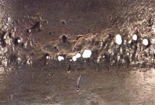
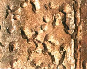
1 A comparison of the Magnetic Flux Leakage and Ultrasonic methods in the detection and measurement of corrosion pitting in ferrous plate and pipe. J. C. Drury I.Eng. M.Inst.NDT Silver Wing (UK) Limited A. Marino Procontrol s.r.l. INTRODUCTION Magnetic Flux Leakage (MFL) and manual Ultrasonics (UT) have been used extensively for the detection and sizing of corrosion pits in ferrous plates and pipes. Users and providers of these inspection services may have different perceptions and expectations of the sensitivity and accuracy of the methods. This paper discusses the underlying principles of the methods and their effect on Probability of Detection (POD) and accuracy. CORROSION PITTING There are many types and mechanisms of corrosion but in this instance we deal exclusively with corrosion that is typical between the pad and the underside of tank bottoms or from water contamination inside the tank. The ultrasonic means of detecting erosion in pipework was so successful during the 1960's that it has given a false impression of the accuracy that will be obtained with pitting type corrosion. To help appreciate the difference we will illustrate erosion and some typical pit shapes. Figure 1 shows erosion whereas Figures 2 to 4 sketch corrosion shapes that have been given the terms "Lake Type", "Cone Type" and "Pipe Type". Figures 5 to 8 are photographs of erosion and typical corrosion of the lake and cone type. It is interesting to note the steps or 'terraces' formed as the corrosion progressed. Lake and pipe types of corrosion are most commonly found in storage tank floors. They are usually the result of moisture ingress between the floor and the pad (underside) or water in the product (topside). Pipe type pitting is relatively uncommon and is usually associated with water droplet erosion or Sulphur Reducing Bacteria (SRB). METHOD PRINCIPLES The principles of both the MFL method and the UT method have been described in detail elsewhere. For the purposes of this paper these are briefly summarised here. Figure 9 illustrates the basic principle of the MFL method. A magnet mounted on a carriage induces a strong magnetic field in the plate or pipe wall. In the presence of a corrosion pit, a magnetic flux leakage field forms outside the plate or pipe wall. An array of sensors is positioned between the magnet poles to detect this flux leakage. The sensors are usually Hall Effect devices or coils; there are advantages and limitations with either type of sensor. Figure 10 illustrates a simple UT set-up using the pulse-echo principle and a twin crystal probe. In this configuration one crystal acts as transmitter and the other as the receiver. The transmitter is isolated from the receiving circuits so that the A-scan display is freed from the presence of a transmission signal. As a result the transmission pulse does not obscure the first back wall echo when testing relatively thin areas of plate or pipe. We shall see that simple digital thickness meters without an A-scan facility are not suitable for either detection or measurement of pitting. PROBABILITY OF DETECTION - MFL.
2 The MFL method uses an array of sensors such that each sensing field overlaps with its neighbour. The probability of detection of any flux leakage signal depends on the amplitude of that leakage field in relation to any noise signals. In other words, the signal to noise ratio is the primary factor governing detection. Some of the parameters affecting the signal to noise ratio are related to the equipment design and performance, and some are related to the floor condition including the geometry of any pitting. Equipment parameters Floor parameters Magnet design Sensor type and layout Speed control Vibration damping Signal processing Detection notification Floor material Scanning surface condition Scanning surface coating Cleanliness Pit depth Pit volume Pit contour Equipment Magnet design The magnet must be strong enough to achieve a flux density in the material being tested that is close to saturation. The carriage design must be such that the magnet system can ride any undulations in the scanning surface without too much variation in the gap between the magnet poles and the test surface (lift off). Clearly, one advantage of using Electro-magnets is that the magnetising force can be adjusted to compensate for different material thicknesses and lift off changes. A practical advantage is also that the magnetic field can be switched off to aid removal of the scanning head from the test surface. The major disadvantages are size and weight. For this reason many scanners resort to permanent magnets using Neodymium - iron - boron in the magnet design. The result is a compact scanning head suitable for wall thicknesses up to 12.5mm, or, at reduced sensitivity, up to 20mm. Greater thicknesses could be achieved provided that a suitable and safe system to place and remove the carriage from the test surface is devised. Sensor type and layout Two types of sensor are in common use, coils and Hall effect devices. In either case the spacing between adjacent elements in the array must be small enough to ensure that there are no gaps in detection across the array. If sensors are arranged in differential pairs for noise cancelling purposes, the layout should take into account the fact that the leakage field may extend 3 or 4 times the diameter of the pit across the array but only about the diameter of the pit in the scanning direction. The voltage signal generated by a given leakage field in a coil sensor is a function of the rate of cutting lines of force. This will be a function of the number of turns in the coil and the forward speed of the scanner. Thus the coil type of sensor is speed sensitive and this should be taken into account in the equipment design. Coils are also more sensitive to lift off variation than some configurations of Hall effect devices. One distinct advantage of the coil sensor is that it appears to be less affected than Hall effect devices by the strong eddy current signal that is generated during the acceleration and deceleration phases of the scanner. Hall effect devices are in principle less sensitive to speed variation, however when filtration is used during signal processing to remove low and high frequency spurious signals, the resulting band pass window imposes some restriction on speed variation. When these devices are arranged to detect the Horizontal component of the leakage field, they are relatively insensitive to the eddy current signal mentioned above, but, like the coil, relatively sensitive to lift off variations. When arranged to detect the Vertical component, they are less
3 sensitive to lift off variations but very sensitive to the eddy current signals. One advantage of this arrangement, however, is that a larger gap between the sensor housing and the test surface can be accommodated which reduces housing wear and allows the housing to clear some of the surface imperfections such as weld spatter. Speed control Some degree of speed control is necessary with all types of sensor but there is less latitude when coils are used. Vibration damping One source of background noise and false indications is due to surface roughness of the scanning surface. This is very common in the case of storage tank floors and above ground pipelines that have not been coated. The resulting corrosion on those surfaces causes the scanning carriage to vibrate the magnet and sensor system. The resulting noise can be reduced in three ways: by fitting broader wheels, by incorporating shock absorbers and by signal processing since the vibration frequency is likely to be higher than that from pit signals. Signal processing The signals from leakage fields are relatively small and need amplification. They also need to be discriminated from unwanted noise. Band pass filters are used to remove the low frequency (eddy current) and high frequency (vibration) noise. Any residual noise can be countered by the use of thresholds set on the defect detection circuit or, in the case of dynamic detection notification displays, by the operator assessing the general noise level. Defect notification There are three ways in current use in which a defect may be drawn to the attention of the operator: - 1. Autostop. The scanner automatically stops when a defect is encountered and a visual display indicates which sensors in the array have detected the pit. The scanner cannot be restarted until the operator has cancelled the indication. The operator marks the floor so that pit depth measurement can be performed. 2. Dynamic display. The operator views a dynamic display indicating the current status of signals across the array. A signal above the general noise level indicates the presence of a pit. In these systems the operator may be assisted by an audible or visual alarm which triggers above a pre-set threshold. The operator marks the floor so that pit depth measurement can be performed. 3. Computer data acquisition. Some systems use a computer to store data from the inspection for subsequent analysis and reporting. This may include software to allow mapping of the tank floor with colour coded indications of material loss. The operator can access the data at the end of each scan in order to mark the floor so that some cross checking of results can be performed. Floor Material Clearly a ferrous material is necessary for MFL, but the magnetic permeability of the ferrous material will affect the results. It follows that the calibration plate or pipe used to set up the equipment should be made of the same grade of steel as the material to be inspected. This is generally not a problem with storage tank floors since with very rare exceptions they are constructed using low carbon mild steels. Greater care is needed when selecting a calibration pipe to ensure that the correct grade of steel is selected. For a given magnetising field, material thickness will affect the degree of saturation achieved and this in turn will affect the flux leakage amplitude for a given pit
4 Scanning surface condition The scanning surface should be clean and free from debris (particularly from corrosion products that may have fallen from the tank roof). Surface roughness may cause vibration noise requiring a relatively high threshold to be set (reduced pit sensitivity). In some cases laying a thin sheet (circa 1mm) of plastic over the scanning surface can alleviate this. Other anomalies such as weld spatter or weld repairs that have been ground flush will give large false indications. It must also be remembered that the MFL method does not discriminate between pitting on the scanning surface and that on the remote surface, however, for pits penetrating 50% or more through the material, the MFL method is more sensitive to remote surface pitting. Scanning surface coating One major advantage of the MFL method is that it is able to function with relatively thick surface coating and maintain reasonable sensitivity. Fibreglass coatings up to 6mm thick on 6.32mm thick floors have been inspected and 20% wall loss detected. Cleanliness MFL is less sensitive to floor surface condition that ultrasonics but heavily ribbed scale can cause false indications and corrosion products can build up on the magnet poles and then give false indications as they break away and pass under the sensor head. Generally removal of product and subsequent water jetting of the surface is sufficient. Pit depth Pit depth is one of the main factors affecting flux leakage amplitude at a particular distance above the test surface. Volume and contour also affect this amplitude and these are discussed below. However within prescribed limitations the amplitude of the flux leakage field can be used to assess the percentage wall loss and thus reduce the amount of cross checking needed. Pit Volume It has been claimed elsewhere that the volume of the pit is the most significant factor affecting signal amplitude and for this reason it is claimed that no quantitative information about the pit can be deduced from the MFL results. Since the claim mostly appears as a bald statement we decided to carry out a study of the effects of volume and depth using modelling techniques and some empirical trials on real corrosion. A series of models of pits of given depth and varying volumes were produced. The results for depths of 40%, 50% and 60% pits in 6.35mm plate are shown at Figure 11. These show that as the volume increases its affect on signal amplitude decreases. This suggests that for typical tank floor corrosion of the cone and lake type it should be possible to "band" corrosion severity with reasonable accuracy using MFL alone. Pipe - like pitting such as that encountered with Sulphur Reducing Bacteria attack, however, are likely to give inaccurate results because the volumes will correspond to the region where the curves in Figure 11 converge. Pit contour Very often people producing test plates with machined pitting choose simple shapes such as flat-bottomed holes (borrowed from ultrasonics) or simple conical impressions using drill bits. It has been shown that the contour of the pit will affect the leakage field. Since corrosion pitting usually progresses in such a way as to produce "terracing" in its profile, we have used artificial pits for calibration purposes that mimic the terracing as shown in Figure 12. These have been used to calibrate the MFL system used in the empirical results shown below. Human factors As with other NDT methods, human factors must be considered in assessing probability of detection. Especially in the case of storage tanks, the environment is not friendly! The
5 interior of the tank is dark, dirty and has the lingering smell of the product. It can at times be extremely hot (+50ºC) or extremely cold (-20ºC) depending on location and season. It is therefore essential that the demands made on the operator are as light as possible. However, the operator must also ensure that the equipment is maintained in the best possible condition and that the calibration routine is carried out with precision. POD Summary for MFL The probability of detection of pitting using the MFL is high within certain limits. With wellmaintained equipment, trained and conscientious operators working on clean unpitted scanning surfaces on material thicknesses up to 10mm thick losses of 20% (sometimes as low as 10%) can be reliably detected. On less clean surfaces and on thicknesses up to 13mm 40% losses can be detected. Within these limits MFL is able to scan at speeds around 0.5m/sec with scan widths from 150mm to 450mm wide. The method is less influenced by surface condition than ultrasonics and for most MFL systems less operator dependant. PROBABILITY OF DETECTION - ULTRASONICS The probability of detection of corrosion pitting using the ultrasonic method is also dependent on many factors. Because the method is rather slower than MFL, it was common practice until recently to use spot checks on a grid pattern in the same way that was used for erosion detection on pipe bends. Clearly the probability of detecting isolated pitting using this technique is negligible. Area scanning is now preferred and can be applied manually using contact scanning or using automated scanning with water irrigated probes. The reflecting surface that is offered by typical corrosion pitting is often poor for ultrasonic purposes and the operator needs to be able to see the character of the signal to avoid errors. For this reason simple digital thickness meters are not suitable for corrosion detection. Equipment with an A-Scan presentation is preferred and this can be complimented by B-Scan and C- Scan facilities. As with the MFL, the factors affecting POD with Ultrasonics include those that relate to the equipment and technique and those that relate to the floor and any pitting that may be present. Equipment Parameters Flaw Detector Probe Type Couplant method and type Scanning technique Calibration Training and experience Floor Parameters Floor Thickness Scanning surface condition Floor coating Pit characteristics Equipment Flaw detector As a minimum it should have an A-Scan display but the use of data storage techniques with facilities for producing both C-Scan and B-Scan images greatly enhances the probability of detection. In particular, these facilities demonstrate that continuous coupling has been achieved during the inspection. Probe Type In many cases the thickness of material being examined is less than 10mm and the scanning surfaces are not completely smooth. This means that the initial pulse of single crystal transducers will occupy a significant portion of the nominal thickness so these transducers are not suitable. Twin crystal (Dual) transducers overcome this problem but it must be remembered that the optimum distance at which the maximum amount of transmitted energy is able to be captured by the receiver is a function of the probe design.
6 Figure 13 illustrates this and shows clearly why reflectors below this distance will give reduced amplitude signals even when the reflecting surface in question is flat and parallel to the scanning surface. The operator should be aware of this possibility especially as corrosion pits are not ideal reflectors and should be prepared to vary the gain when backwall echoes are 'lost'. The rough surfaces encountered will rapidly wear Perspex shoes and change the beam angle so it is necessary to fit a wear ring to the probe. The crystal size should be between 10 and 15mm diameter. Couplant method and type Two methods of coupling ultrasound to the material are in current use. For manual scanning the contact method is used, whilst for automated and semi-automated scanning, water irrigation is preferred. In either case it is essential that the couplant is able to 'wet' the surface. Suitable gels are available for manual scanning and for water irrigation it may be necessary to add a wetting agent (soap). Scanning technique It should be obvious that taking spot readings on a grid pattern is only suitable for detecting areas of general corrosion and is useless in detecting isolated pits. Therefore it is necessary to use an area scan technique with a suitable overlap to ensure coverage by the effective area of the probe. With manual scanning it is better to use a fairly rapid probe movement with suitable calibration than to use a slow painstaking approach to the detection phase. This is because the human eye naturally responds to a sudden change (movement) in signal pattern. Once the pit has been detected, a more careful investigation of pit depth can be carried out. Calibration For the detection phase of the inspection when using manual scanning, it is better to calibrate the flaw detector on the actual test material by selecting an area on the floor where the thickness is known to be at the nominal plate thickness. The timebase is then set to display 3 backwall echoes positioned at 3, 6 and 9. The gain should be set so that the third backwall echo is at 80% full screen height. With this arrangement, using the fast scanning movement described above, loss of couplant will show as a vertical drop in all three echoes. The presence of a pit will show as a progressive loss (3 rd then 2 nd and then 1 st echo) coupled with a general movement of the signals towards zero. With practice the eye becomes well adapted to recognise these patterns. Training and experience The detection of corrosion pits is more difficult than simple thickness measurement or the detection of laminations or erosion. The slow scanning technique, with a timebase calibrated to display only one backwall echo, used by some operators is prone to miss pits that have poor reflectivity such as the conical types. Operators often say that they 'lost' the signal due to poor scanning surface when they have just encountered a pit. Specific training and experience is required for corrosion detection. Floor Thickness Thinner wall thicknesses present the main difficulty when using the ultrasonic method. Below 6mm the signal from a good reflector is reduced as described above and shown in Figure 13. The operator must be aware that more gain will be required. For thicker sections (above 12mm) the ultrasonic method is far less restricted than MFL, however the POD limitations with respect to shape and reflectivity of pits still apply.
7 Scanning surface condition The ultrasonic method is much more sensitive to the condition of the scanning surface than is the MFL method. This applies to both contact scanning and irrigated 'gap' scanning. Reflections in the couplant layer create 'noise' that obscures part of the timebase as shown in Figure 14. Since the velocity of sound in the couplant is about one quarter of the velocity in the material, top surface pits may give clear echoes that appear to show a reduced wall thickness. Figure 15 illustrates a lake type pit 1mm deep. The echo from the bottom of the pit appears at a steel thickness of 4mm. If unnoticed the operator may report a 6mm deep underfloor pit in a 10mm plate (60% loss). The same pit is likely to be misinterpreted with automated and semi-automated systems whether or not they use interface triggering and/or echo-to-echo monitoring. Floor Coatings Painted and epoxy coated floors in which the coating is in good condition and has been applied from new present few problems to ultrasonic inspection and pit detection. The accuracy of measurement of remaining wall thickness is improved if the echo-to-echo method is used to eliminate paint thickness errors. Thicker, fibreglass coatings present more of a problem. Although in theory it may be possible to inspect through such a coating if the adhesion to the metal surface is good, it is seldom suitable for inspection. Pit characteristics The easiest pits to detect are the lake type because in the deepest region they are relatively parallel to the scanning surface and can be expected to give reasonable reflectivity. On the other hand the conical pits tend to reflect sound away from the receiver and the centre of the pit is often too small in area to give a strong signal (Figure 16). These are the pits that are most likely to be missed by the ultrasonic operator. Often one of the 'terrace' facets is the strongest reflector and the pit is detected but its depth is underestimated. Pipe like pits such as those typical of SRB attack present very small targets to the ultrasonic beam and may also be as difficult to detect. Where the reflectivity of the pit is favourable, the ultrasonic method is capable of detecting smaller changes of thickness than the MFL method but, since the corrosion allowance is often as much as 50%, this advantage is not always significant. POD Summary for Ultrasonics On good scanning surfaces the probability of detecting Lake Type pits is high. For poor scanning surfaces and for Cone Type pitting, the probability of detection is less satisfactory. To some extent the POD can be improved using the automated techniques with data storage and at least a C-scan presentation using colour coding to 'band' thickness. SOME PRACTICAL RESULTS Some sections of floor were cut from storage tank bottoms after MFL inspection. Sections were taken from areas where underfloor corrosion was reported and also from areas where there was said to be no corrosion that was deeper than 20%. Some of the sections had been inspected using the Silver Wing 'Floormap' system that produced a map of the floor with colour coded indications of corrosion, each colour representing a 'band' of percentage wall loss. The corroded sections were subjected to mechanical pit depth measurement and the results compared with the MFL report. The pitting included both lake and cone examples. The approximate locations of the pits were marked on the opposite side of the plates (scanning surface) and two teams of UT operators were asked to locate the pits and measure their depth. Figures 17 to 21 are photographs of some of the corrosion detected. Figures 22 and 23 are graphs showing actual pit depth against reported depths for the two UT teams. Figure 24 show the same for the MFL results. It can be seen that on average the MFL system overestimates the depth of pitting by about 10% whereas the ultrasonic method has
8 underestimated by about 10%. However one UT team missed two of the pits even though the approximate location had been marked. CONCLUSIONS Both methods have limitations in the thickness range that can be reliably inspected and the smallest pit that can be detected. Within the limitations described for MFL, the probability of detection of isolated pitting is better than ultrasonics and the method is also quicker than ultrasonics so more economic. In terms of accuracy of depth measurement, both methods have the same percentage error though in opposite senses. Since there is a remote chance that the floor material may not be mild steel and thus may have a permeability that differs from the calibration plate, it is always necessary to carry out at least limited cross checking of MFL results with UT before relying on MFL depth assessment.
9 EROSION Fig. 1 LAKE TYPE PIT Fig. 2 CONE TYPE PIT Fig. 3 PIPE TYPE PIT Fig. 4

10 Fig 5 Fig 6

11 Fig 7 Fig 8
12 Magnet Carriage Sensor Head Leakage Field Plate Fig Fig 10
13 Gauss % 50% 40% Volume Cu. mm. Figure 11
14 Plate Profile 40% Hole Typical 40% pit Figure 12 Dual Probe T R Test surface Figure 13
15 Noise Figure 14 Spurious echo Pit Figure 15


16 Figure 16 Sample 1 Top surface Figure 17 Sample 1 Underside Figure 18


17 Figure 19 Figure 20 Sample 2 underside pitting Figure 21
18 Defect Depth Correlation Estimated Depth (% Loss) UT Team 'A' True Depth (% Loss) Fig Defect Depth Correlation 90 Estimated Depth (% Loss) UT Team 'B' True Depth (% Loss) Fig. 23
19 100 Defect Depth Correlation Estimated Depth (% Loss) MFL True Depth (% Loss) Fig. 24
Pulsed Eddy Current (PEC) Inspection through Insulation
 Inspection through Insulation") Pulsed Eddy Current (PEC) Inspection through Insulation Inspection through insulation opens unexpected opportunities Shell Global Solutions in Amsterdam has developed over the past few years an inspection
Pulsed Eddy Current (PEC) Inspection through Insulation Inspection through insulation opens unexpected opportunities Shell Global Solutions in Amsterdam has developed over the past few years an inspection
EFFECTIVE & RELIABLE INSPECTION OF FIN-FAN COOLER TUBES
 7 th MENDT Conference Bahrain - 2015 EFFECTIVE & RELIABLE INSPECTION OF FIN-FAN COOLER TUBES ANDREAS BOENISCH & ABDUL RAHMAN TAQATEQ CONTENT - Short overview Fin Fan Cooler & Tube Types, Tube corrosion
New Highly Productive Phased Array Ultrasonic Testing Machine for Aluminium Plates for Aircraft Applications
 19 th World Conference on Non-Destructive Testing 2016 New Highly Productive Phased Array Ultrasonic Testing Machine for Aluminium Plates for Aircraft Applications Christoph HENKEL 1, Markus SPERL 1, Walter
EXPERIMENTAL RESULTS OF GUIDED WAVE TRAVEL TIME TOMOGRAPHY
 18 th World Conference on Non destructive Testing, 16-20 April 2012, Durban, South Africa EXPERIMENTAL RESULTS OF GUIDED WAVE TRAVEL TIME TOMOGRAPHY Arno VOLKER 1 and Hendrik VOS 1 TNO, Stieltjesweg 1,
Importance of Wave Height Measurement in Wave Solder Process Control
 Importance of Wave Height Measurement in Wave Solder Process Control By: Patrick McWiggin, Technical Director, SolderStar Ltd It is still common place to simply capture temperature profile measurements
Employer s Unit of Competence Magnetic particle testing of materials, products and plant
 Employer s Unit of Competence Magnetic particle testing of materials, products and plant Image - if cover page required Supported by lead employer Overview This unit identifies the competencies required
Acoustic Pulse Reflectometry Brings an End to Tube Inspection Sampling By Dr. Noam Amir, Chief Technology Officer, AcousticEye
 SINCE2011 Singapore International NDT Conference & Exhibition, 3-4 November 2011 Acoustic Pulse Reflectometry Brings an End to Tube Inspection Sampling By Dr. Noam Amir, Chief Technology Officer, AcousticEye
Survey of Underwater NDT Technologies for Offshore Assets
 Survey of Underwater NDT Technologies for Offshore Assets Ayman Amer, Fadl Abdellatif, Ali Outa, Hassane Trigui, Sahejad Patel, Ameen Obedan, Fernando Diaz Ledezma, Hamad Al Saiari and Ihsan Taie, Saudi
TECHNICAL REPORT ON CAPACITY BUILDING IN USE OF EDDY CURRENT TESTING EQUIPMENT
 REFERENCE NO. PNRA-CNS-NDT-49-13 MAY, 2013 TECHNICAL REPORT ON CAPACITY BUILDING IN USE OF EDDY CURRENT TESTING EQUIPMENT PAKISTAN NUCLEAR REGULATORY AUTHORITY P.O. BOX 1912, ISLAMABAD i Intentionally
Instrumentation & Data Acquisition Systems
 Instrumentation & Data Acquisition Systems Section 3 -Level Robert W. Harrison, PE Bob@TheHarrisonHouse.com Made in USA 1 Level Section Question Which level measuring technology is the best solution when
Paper #: POWER
 Proceedings of POWER2008 ASME Power 2008 July 22-24, 2008, Orlando, Florida, USA Paper #: POWER2008-60061 THE USE OF AN EDDY CURRENT INSPECTION OF BRASS TUBES IN A SURFACE CONDENSER TO PROVIDE A CONDITION
DIFFERENT SOLUTIONS TO INSPECT PLATFORM RISERS. By R van Agthoven and H Quakkelsteijn, ApplusRTD, Rotterdam, The Netherlands
 DIFFERENT SOLUTIONS TO INSPECT PLATFORM RISERS By R van Agthoven and H Quakkelsteijn, ApplusRTD, Rotterdam, The Netherlands SUMMARY The need for the inspection of pipelines and risers is growing, as the
Guided Wave Testing (GWT)
") Guided Wave Testing (GWT) Use of guided wave testing for the detection and monitoring of corrosion under insulation Peter Philipp Independent GWT consultant Level 3 GUL Level 3 PCN GWT BINDT-ICorr. - 12/05/2013
Guided Wave Testing (GWT) Use of guided wave testing for the detection and monitoring of corrosion under insulation Peter Philipp Independent GWT consultant Level 3 GUL Level 3 PCN GWT BINDT-ICorr. - 12/05/2013
Standard Practice for Eddy-Current Examination of Steel Tubular Products Using Magnetic Saturation 1
 Designation: E 309 95 An American National Standard Standard Practice for Eddy-Current Examination of Steel Tubular Products Using Magnetic Saturation 1 This standard is issued under the fixed designation
Flaw Detection Capabilities with Eddy Current Array Technology
 Flaw Detection Capabilities with Eddy Current Array Technology 2018 ASNT Annual Conference Jesse Herrin 1 Agenda Common NDT Techniques for Surface Flaws Eddy Current Array (ECA) Testing and Benefits Scan
INNOVATIVE ENGINEERING SUPERIOR SERVICES. Robotic Online Storage Tank Floor Inspection Services
 INNOVATIVE ENGINEERING SUPERIOR SERVICES Robotic Online Storage Tank Floor Inspection Services Storage Tank Floor Condition Assessment Without Taking Tanks Out of Service Eliminate the high cost of tank
Drilling Efficiency Utilizing Coriolis Flow Technology
 Session 12: Drilling Efficiency Utilizing Coriolis Flow Technology Clement Cabanayan Emerson Process Management Abstract Continuous, accurate and reliable measurement of drilling fluid volumes and densities
Level MEASUREMENT 1/2016
 Level MEASUREMENT 1/2016 AGENDA 2 A. Introduction B. Float method C. Displacer method D. Hydrostatic pressure method E. Capacitance method G. Ultrasonic method H. Radar method I. Laser method J. Level
A review of best practices for Selection, Installation, Operation and Maintenance of Gas meters for Flare Applications used for Managing facility
 A review of best practices for Selection, Installation, Operation and Maintenance of Gas meters for Flare Applications used for Managing facility mass balance and compliance 1. What, When and Why? 2. Flare
Vortex Flow Meter Wafer or Flange Connection. - Steam - Liquid - Gas
 Vortex Flow Meter Wafer or Flange Connection - Steam - Liquid - Gas Working Principle & Circuit Diagram Working Principle When a column body placed in flowing fluids in pipe, a series of vortices will
TSC developed the practical use of magnetostrictive method for strain measurement and it is embodied in the StressProbe instrument.
 TSC StressProbe StressProbe Background OVERVIEW OF TECHNIQUE Magnetisation of ferromagnetic materials such as iron and mild steel have an interaction with elastic strain called magnetostriction, that is,
The Use of Ultrasonic Inspections at Elevated Temperature
 18th World Conference on Nondestructive Testing, 16-20 April 2012, Durban, South Africa The Use of Ultrasonic Inspections at Elevated Temperature Alex McLAY, Jan VERKOOIJEN, TÜV Rheinland Sonovation 4906AZ
2600T Series Pressure Transmitters Plugged Impulse Line Detection Diagnostic. Pressure Measurement Engineered solutions for all applications
 Application Description AG/266PILD-EN Rev. C 2600T Series Pressure Transmitters Plugged Impulse Line Detection Diagnostic Pressure Measurement Engineered solutions for all applications Increase plant productivity
AN31E Application Note
 Balancing Theory Aim of balancing How an unbalance evolves An unbalance exists when the principle mass axis of a rotating body, the so-called axis of inertia, does not coincide with the rotational axis.
What hull material types will the system work on? Do I still need an antifoul paint?
 1. The Hull What hull material types will the system work on? The system is effective on all GRP (Glass Reinforced Plastic), STEEL and ALUMINIUM hulls up to thickness of 70mm. Unfortunately the system
Wire ropes condition monitoring: conception and embodiment
 NDT2015, Hyderabad November 26-28, 2015 More info about this article: http://www.ndt.net/?id=21134 Wire ropes condition monitoring: conception and embodiment Alexander Mironenko INTRON PLUS LTD., Moscow,
AIRMOUNT VIBRATION ISOLATION
 MOUNT VIBRATION ISOLATION SELECTION AND ISOLATION FORMULA Refer to the selection guide on page 33 for Airmount load and isolation capabilities. Follow this procedure: 1. LOAD CAPACITY Select one or two
14/10/2013' Bathymetric Survey. egm502 seafloor mapping
 egm502 seafloor mapping lecture 10 single-beam echo-sounders Bathymetric Survey Bathymetry is the measurement of water depths - bathymetry is the underwater equivalent of terrestrial topography. A transect
Effect of a Backplate Using in Electromagnetic Induction Method for Permittivity Measurement
 Effect of a Backplate Using in Electromagnetic Induction Method for Permittivity Measurement W. Matsunaga, K. Mizukami 1, Y. Mizutani, A. Todoroki and Y. Suzuki School of Engineering, Department of Mechanical
Acoustic Emission Testing of The Shell 0f Electromagnetic Valve
 17th World Conference on Nondestructive Testing, 25-28 Oct 2008, Shanghai, China Acoustic Emission Testing of The Shell 0f Electromagnetic Valve guozhen XU 1, yiwei CHEN 1, zhihua CAO 2 ABSTRACT Shanghai
Inspection of CANDU Reactor Pressure Tubes Using Ultrasonics
 17th World Conference on Nondestructive Testing, 25-28 Oct 2008, Shanghai, China Inspection of CANDU Reactor Pressure Tubes Using Ultrasonics Michael TRELINSKI Inspection & Maintenance Services Ontario
INSPECTION OF RECOVERY BOILERS
 INSPECTION OF RECOVERY BOILERS W. B. A. (Sandy) Sharp SharpConsultant, Columbia, Maryland, U.S.A. TAPPI Kraft Recovery Short Course St. Petersburg, Florida, January 7-10, 2008 OUTLINE Purpose of inspections
Monitoring or Inspection
 Comparison of Corrosion Monitoring Systems Monitoring or Inspection Date: September 2016 There is often some confusion between the words monitoring and inspection when used in reference to measuring metal
DESIGNED AND MANUFACTURED IN ENGLAND CLIPPER DEPTH DEPTH METRES ECHO SOUNDER.
 DESIGNED AND MANUFACTURED IN ENGLAND CLIPPER DEPTH DEPTH 7 METRES ECHO SOUNDER INTRODUCTION 2 INSTALLING THE DISPLAY 2 INSTALLING THE TRANSDUCER 3 NOTES ON ELECTRICAL INTERFERENCE 5 GETTING STARTED 5 OPERATIONAL
Process Control Loops
 In this section, you will learn about how control components and control algorithms are integrated to create a process control system. Because in some processes many variables must be controlled, and each
Locator Locator-D-Lux Air-Saver G1 Air-Saver G2
 170663_air_saving_products 17-02-2011 16:42 Pagina 1 Locator Locator-D-Lux Air-Saver G1 Air-Saver G2 AIR SAVING PRODUCTS 170663_air_saving_products 17-02-2011 16:42 Pagina 2 170663_air_saving_products
BOTTOM MAPPING WITH EM1002 /EM300 /TOPAS Calibration of the Simrad EM300 and EM1002 Multibeam Echo Sounders in the Langryggene calibration area.
 BOTTOM MAPPING WITH EM1002 /EM300 /TOPAS Calibration of the Simrad EM300 and EM1002 Multibeam Echo Sounders in the Langryggene calibration area. by Igor Kazantsev Haflidi Haflidason Asgeir Steinsland Introduction
3.6 Magnetic surveys. Sampling Time variations Gradiometers Processing. Sampling
 3.6 Magnetic surveys Sampling Time variations Gradiometers Processing Sampling Magnetic surveys can be taken along profiles or, more often, on a grid. The data for a grid is usually taken with fairly frequent
MIL-STD-883H METHOD EXTERNAL VISUAL
 * EXTERNAL VISUAL 1. PURPOSE. The purpose of this test method is to verify the workmanship of hermetically packaged devices. This test method shall also be utilized to inspect for damage due to handling,
In-Service Inspection of Ammonia Storage Tanks
 White Paper In-Service Inspection of Ammonia Storage Tanks By: Ole Noerrekaer Mortensen, Business Manager, Advanced NDT Global at FORCE Technology Personnel ready for mounting the Inspection System in
Sensor for Air Bubble Detection at Liquid Filled Tubes. SONOCHECK Type ABD06.xx. Operating Manual
 Sensor for Air Bubble Detection at Liquid Filled Tubes SONOCHECK Type ABD06.xx Operating Manual Manufacturer: Model: Type: SONOTEC Ultraschallsensorik Halle GmbH Air Bubble Detector ABD06.xx SONOTEC Ultraschallsensorik
TransPort PT878GC Panametrics Portable Gas Ultrasonic Flowmeter. GE Sensing. Applications. Features
 Applications The TransPort PT878GC clamp-on gas flowmeter is a complete ultrasonic flow metering system for measurement of most gases, including: Natural gas Compressed air Fuel gases Erosive gases Corrosive
Air Diving Inspection of ABC Mock-Up Caisson Project 123
 Air Diving Inspection of ABC Caisson Project 123 Client: CLIENT Facility: CDE, Norway Item Inspected: ABC Caisson Inspection Method: Manual Surface Eddy Current Date Commenced: 04 November 2013 Date of
RECENT IMPROVEMENTS REGARDING ULTRASONIC CRACK INSPECTION OF PIPELINES Herbert Willems, Thomas Hennig NDT Global, Stutensee, Germany
 RECENT IMPROVEMENTS REGARDING ULTRASONIC CRACK INSPECTION OF PIPELINES Herbert Willems, Thomas Hennig NDT Global, Stutensee, Germany ABSTRACT Crack inspection of pipelines using conventional ultrasonic
INTERNAL AXIAL CORROSION IN OFFSHORE PIPELINES: INSPECTION AND ASSESSMENT. By: Dr. Christoph Jäger, Abdullahi Atto, NDT Global, Germany
 INTERNAL AXIAL CORROSION IN OFFSHORE PIPELINES: INSPECTION AND ASSESSMENT By: Dr. Christoph Jäger, Abdullahi Atto, NDT Global, Germany Abstract Internal long axial corrosion is the most common corrosion
485 Annubar Primary Flow Element Installation Effects
 ROSEMOUNT 485 ANNUBAR 485 Annubar Primary Flow Element Installation Effects CONTENTS Mounting hole diameter Alignment error Piping Geometry Induced Flow Disturbances Pipe reducers and expansions Control
Fitness for Service Assessment of Ageing Pressure Vessel Experiencing External Corrosion: A Case Study
 The International Journal Of Engineering And Science (IJES) Volume 6 Issue 2 Pages PP 12-16 2017 ISSN (e): 2319 1813 ISSN (p): 2319 1805 Fitness for Service Assessment of Ageing Pressure Vessel Experiencing
LS-UT Ultrasonic Level Transmitter
 Four Elms Road Edenbridge Kent TN8 6AB UK Features & Benefits Maintenance free Simple set-up procedure IP86 housing (2m for 24 hours) Low consumption Locking nut supplied Technical Overview The LS-UL ultrasonic
Lab 4: Pressure Gradients over a Wing
 2009 Lab 4: Pressure Gradients over a Wing Innovative Scientific Solutions Inc. 2766 Indian Ripple Road Dayton, OH 45440 (937)-429-4980 Lab 4: Pressure Gradients over a Wing Introduction: Like the previous
The M-Series Eletta Flow Meter High accuracy DP Flow Meter with multiple functions
 The M-Series Eletta Flow Meter High accuracy DP Flow Meter with multiple functions Flow Meter with multiple functions for gases and liquids M3 The M-series Flow Meter, with its versatile and user-friendly
TEK-THERMAL 1700B. Thermal Mass Flowmeter. FLOW. Technology Solutions
 Technology Solutions TEK-THERMAL 1700B Thermal Mass Flowmeter FLOW www.tek-trol.com Flow Level Temperature Pressure Valves Analyzers Accessories TekValSys Introduction Tek-Thermal 1700B Thermal Mass Flowmeters,
Job Sheet 1 Blade Aerodynamics
 Job Sheet 1 Blade Aerodynamics The rotor is the most important part of a wind turbine. It is through the rotor that the energy of the wind is converted into mechanical energy, which turns the main shaft
How Accurate Are Gravity Sewer Flow Meters?
 The following discusses the various flow monitoring technologies for use in gravity sewers and their ability to measure accurate flow rates. Before jumping into the various theories of operation and technical
Flow in a shock tube
 Flow in a shock tube April 30, 05 Summary In the lab the shock Mach number as well as the Mach number downstream the moving shock are determined for different pressure ratios between the high and low pressure
Ultrasonic Flowmeter USZ 08
 Ultrasonic Flowmeter USZ 08 PRODUCT INFORMATION Reliable Measurement of Gas Fields of application, method of operation and construction 2 Fields of application The ultrasonic flowmeter is an advanced measuring
NERC GEOPHYSICAL EQUIPMENT FACILITY LOAN 904 SCIENTIFIC REPORT
 NERC GEOPHYSICAL EQUIPMENT FACILITY LOAN 904 SCIENTIFIC REPORT M. Disney, N. MacBean Department of Geography, University College London, Pearson Building, Gower Street, London, WC1E 6BT. Tel. 020 7679
WP Eliminating Oxygen from the Purge Gas and the use of Monitoring Equipment
 Part 4 WP - 269 Eliminating Oxygen from the Purge Gas and the use of Monitoring Equipment Even using specialised weld purging equipment does not guarantee defect free welds. Control of the oxygen content
CrimpFlex Crimping Guidelines
 The following guidelines are suggestions to the design engineer and quality control personnel on proven methods of incorporating the CrimpFlex? contact into their designs and into their manufacturing and
J. J. Daly Metal Improvement Company Paramus New Jersey USA
 Shot Peening-Current Trends, Future Prospects J. J. Daly Metal Improvement Company Paramus New Jersey USA The shot peening process is sparingly used compared to other processes such as heat treating, plating,
DEVICES FOR FIELD DETERMINATION OF WATER VAPOR IN NATURAL GAS Betsy Murphy MNM Enterprises 801 N. Riverside Drive Fort Worth, Texas 76111
 INTRODUCTION Water vapor in natural gas has more than a substantial effect on the quality of the gas stream. Without quality measurement of water vapor the gas is basically not saleable. Contracts are
OPERATION. Estimated kerf width compensation. HPR260 Manual Gas Instruction Manual 4-9
 Estimated kerf width compensation The widths in the chart below are for reference. Differences between installations and material composition may cause the specific user results to vary from those shown
CORRELATION BETWEEN SONAR ECHOES AND SEA BOTTOM TOPOGRAPHY
 CORRELATION BETWEEN SONAR ECHOES AND SEA BOTTOM TOPOGRAPHY JON WEGGE Norwegian Defence Research Establishment (FFI), PO Box 115, NO-3191 Horten, Norway E-mail: jon.wegge@ffi.no False alarms resulting from
Royce Interface Level Analyzer and Sensors
 Royce Interface Level Analyzer and Sensors Model 2511A Interface Level Analyzer The Model 2511A is capable of having the ultrasonic speed of sound signal from its transducers changed by the user in applications
INSPECTION OF MULTI-DIAMETER PIPELINES OPERATING AT LOW PRESSURE. Stefan Vages > ROSEN Group
 INSPECTION OF MULTI-DIAMETER PIPELINES OPERATING AT LOW PRESSURE Stefan Vages > ROSEN Group PIPELINE TECHNOLOGY JOURNAL 7 ABSTRACT Particularly in the 1940s and 1950s, gas pipeline systems were not necessarily
deltaflowc deltaflowc Venturi or Probe
 deltaflowc Mass Flowmeter for Gases - Multivariable with ultra fast dp, p and T-sensors - Compact, accurate and user-friendly - Ideal for OEMs deltaflowc Venturi or Probe Precise mass flow metering deltaflowc
Inspection Effectiveness and its Effect on the Integrity of Pipework
 ECNDT 2006 - Fr.2.3.4 Inspection Effectiveness and its Effect on the Integrity of Pipework Jan Heerings 1, Norbert Trimborn 2, Adriaan den Herder 1 ABSTRACT In order to control the integrity of a pipe
Engineering Data Sheet
 Page 1 of 6 CE MARKING AND THE PRESSURE EQUIPMENT DIRECTIVE 97/23/EC Valves must be installed into a well designed system and it is recommended that the system be inspected in accordance with the appropriate
ACCURACY, PERFORMANCE, AND HANDLING OF OIL-FILLED DIGIQUARTZ PRESSURE INSTRUMENTATION
 Application Note Doc. G8108-001 Rev. A - 23-Jul-02 ACCURACY, PERFORMANCE, AND HANDLING OF OIL-FILLED DIGIQUARTZ PRESSURE INSTRUMENTATION For more information regarding Digiquartz products contact: Paroscientific,
JAPANESE PD EXAMINATIONS FOR DEPTH SIZING OF SCC IN AUSTENITIC STAINLESS STEEL PIPES FROM 2006 TO 2012
 JAPANESE PD EXAMINATIONS FOR DEPTH SIZING OF SCC IN AUSTENITIC STAINLESS STEEL PIPES FROM 2006 TO 2012 Keiji Watanabe, Hajime Shohji, and Koichiro Hide PD center, Central Research Institute of Electric
TIGHTNESS. Glass sealing Thanks to our glass-sealing technology, ODU products can meet the most demanding tightness requirements.
 TIGHTNESS Glass sealing Thanks to our glass-sealing technology, ODU products can meet the most demanding tightness requirements. ODU has the necessary expertise for developing and manufacturing connectors
BLOCKAGE LOCATION THE PULSE METHOD
 BLOCKAGE LOCATION THE PULSE METHOD Presented by John Pitchford Pitchford In-Line Author James Pitchford ABSTRACT Pipeline blockages can result from a number of different mechanisms: wax or solid hydrates
DUALEM EM EQUIPMENT. Geostudi Astier srl Via Nicolodi, Livorno Italy
 DUALEM EM EQUIPMENT DUALEM instruments (e.g. the DUALEM-1) incorporate a DUALEM sensor as well as an internal WAAS-enabled GPS receiver, a hand-held weatherproof display/keypad/power-supply, a carrying
 ACFM ARRAY PROBE TECHNOLOGY WELD INSPECTION DATA Array probe scan on test piece with longitudinal and transverse cracks. ALTERNATIVE CONTOUR PLOT REDUCING COSTS FOR OPERATORS REMOTELY DEPLOYED ACFM INSPECTION
Best Practice for Calibrating LTH Conductivity Instruments
 Application Note Best Practice for Calibrating LTH Conductivity Instruments As accurate process measurement becomes an everyday requirement it is vital to be able to calibrate conductivity instruments
Multiple Pressure Booster Systems With Variable Speed Controller Type BL
 Multiple Pressure Booster Systems With Variable Speed Controller Type BL General Characteristics - Single or multistage pumps - Horizontal or vertical mounting - Total head 30m ~ 250m - Material construction:
PUBLISHED PROJECT REPORT PPR850. Optimisation of water flow depth for SCRIM. S Brittain, P Sanders and H Viner
 PUBLISHED PROJECT REPORT PPR850 Optimisation of water flow depth for SCRIM S Brittain, P Sanders and H Viner Report details Report prepared for: Project/customer reference: Copyright: Highways England,
Depth/Level. Druck Submersible Pressure Sensors Product Guide. GE Sensing. Applications. Features
 Features High accuracy Excellent reliability Robust construction Harsh media compatible High stability Low power/pulsed power operation Applications Bore hole monitoring River level Tank level Tide and
B L A C K H A L L. larner-johnsonvalve presentation
 larner-johnsonvalve presentation History! The Larner-Johnson valve was originally designed and developed in 1920 s for use on hydraelectric power plants in the U.S.A., where it pioneered the application
Wade Reynolds 1 Frank Young 1,2 Peter Gibbings 1,2. University of Southern Queensland Toowoomba 4350 AUSTRALIA
 A Comparison of Methods for Mapping Golf Greens Wade Reynolds 1 Frank Young 1,2 Peter Gibbings 1,2 1 Faculty of Engineering and Surveying 2 Australian Centre for Sustainable Catchments University of Southern
Per Section I of the ASME
 notifies the control room or other Maintenance Safer & Easier remote locations that a probe column The system s intelligence can BOILER INSPECTION GUIDELINES FOR distinguish dirty probes from BOILER INSPECTION
ACCURATE PRESSURE MEASUREMENT FOR STEAM TURBINE PERFORMANCE TESTING
 ACCURATE PRESSURE MEASUREMENT FOR STEAM TURBINE PERFORMANCE TESTING Blair Chalpin Charles A. Matthews Mechanical Design Engineer Product Support Manager Scanivalve Corp Scanivalve Corp Liberty Lake, WA
PIG MOTION AND DYNAMICS IN COMPLEX GAS NETWORKS. Dr Aidan O Donoghue, Pipeline Research Limited, Glasgow
 PIG MOTION AND DYNAMICS IN COMPLEX GAS NETWORKS Dr Aidan O Donoghue, Pipeline Research Limited, Glasgow A model to examine pigging and inspection of gas networks with multiple pipelines, connections and
Mass Spec will not Autotune
 Mass Spec will not Autotune Applies to 5973A/N MSD What could be the problem? There could be several things that would cause your Mass Spec not to Autotune. The most common, easily corrected Autotune problems
Point level switches for safety systems
 Point level switches for safety systems By: Bill Sholette Level Products Business Manager Northeast US - Endress+Hauser Point level switches are often used in applications designed to prevent accidents.
Non Intrusive Inspection for process pressure vessels by Advanced and Common NDT techniques save cost whilst enhance safety and reliability
 Non Intrusive for process pressure vessels by Advanced and Common NDT techniques save cost whilst enhance safety and reliability B.C. Mohan, M.C.Jeyasekhar, More info about this article: http://www.ndt.net/?id=22153
GB/T Translated English of Chinese Standard: GB/T NATIONAL STANDARD OF THE
 Translated English of Chinese Standard: GB/T8361-2001 www.chinesestandard.net Sales@ChineseStandard.net GB NATIONAL STANDARD OF THE PEOPLE S REPUBLIC OF CHINA GB/T 8361-2001 Replacing GB/T 8361-1987 The
Industrial Compressed Air. Ultrasonic Leak Detection Survey Guide
 Industrial Compressed Air Guide Introduction For many manufacturers compressed air represents the second or third highest utility cost in their facility. Without an effective maintenance program in place
TransPort PT878GC Panametrics Ultrasonic Portable Gas Flowmeter. GE Infrastructure Sensing. Features. Applications
 Applications The TransPort PT878GC clamp-on gas flowmeter is a complete ultrasonic flow metering system for measurement of most gases, including: Natural gas Compressed air Fuel gases Erosive gases Corrosive
SPECIFYING MOTIONLESS MIXERS
 SPECIFYING MOTIONLESS MIXERS The operating cost for the energy necessary to mix fluids with a motionless mixer is usually far lower than for any competitive mixing technique. An extruder which melts, mixes
Infrared Thermography Inspection Guidelines. Date Issued:
 Infrared Thermography Inspection Guidelines Date Issued: 2002 01 29 Created By: Approved By: L. Henderson G. Durnford Table Of Contents Table Of Contents...i POLICY STATEMENT...1 APPLICABLE INTERNATIONAL
Check Valve Diagnosis by Sectorial Scanning Phased Array Ultrasonic Technique
 19 th World Conference on Non-Destructive Testing 2016 Check Valve Diagnosis by Sectorial Scanning Phased Array Ultrasonic Technique Héctor Mariano CALAS DEL CASTILLO 1, Bautista DE LA FUENTE 1, Victor
New power in production logging
 New power in production logging Locating the zones where fluids enter the wellbore in a producing or injecting well is an important aspect of production logging. It is relatively straightforward to establish
THERMALLING TECHNIQUES. Preface
 DRAFT THERMALLING TECHNIQUES Preface The following thermalling techniques document is provided to assist Instructors, Coaches and Students as a training aid in the development of good soaring skills. Instructors
TV-114 TV-114-A Wind Speed Sensor User s Manual
 Relied on Worldwide in the Most Extreme Conditions TV-114 TV-114-A Wind Speed Sensor User s Manual Texas Electronics, Inc. Dallas, TX 75237 Fax.214.631.4218 4230 Shilling Way Tel.214-631-2490 www.texaselectronics.com
3.0 Pressure Transmitter Selection
 3.0 Pressure Transmitter Selection Each Tronic Line pressure transmitter has different features to meet specific performance, environmental, and price requirements. It is not possible to describe every
AC : MEASUREMENT OF HYDROGEN IN HELIUM FLOW
 AC 2010-2145: MEASUREMENT OF HYDROGEN IN HELIUM FLOW Randy Buchanan, University of Southern Mississippi Christopher Winstead, University of Southern Mississippi Anton Netchaev, University of Southern Mississippi
HOW TO NOT MEASURE GAS - ORIFICE. Dee Hummel. Targa Resources
 HOW TO NOT MEASURE GAS - ORIFICE Dee Hummel Targa Resources Introduction Measuring natural gas is both a science and an art. Guidelines and industry practices explain how to accurately measure natural
Method of case hardening depth testing by using multifunctional ultrasonic testing instrument
 IOP Conference Series: Materials Science and Engineering PAPER OPEN ACCESS Method of case hardening depth testing by using multifunctional ultrasonic testing instrument To cite this article: Y A Salchak
AI TKA '[ Attorney Docket No Date: 28 June 2007
 AI TKA '[ DEPARTMENT OF THE NAVY NAVAL UNDERSEA WARFARE CENTER DPVSION NEWPORT OFFICE OF COUNSEL PHONE: (401) 832-3653 FAX: (401) 832-4432 NEWPORT DSN: 432-3653 Attorney Docket No. 84854 Date: 28 June
Truck-mounted Mass Flow Metering for LPG Delivery
 Truck-mounted Mass Flow Metering for LPG Delivery Itron, Inc. 1310 Emerald Rd. Greenwood, SC 29646 Introduction The mathematician Gustave De Coriolis first described the Coriolis Effect, which is an inertial