IVAC PCAM Syringe Pump. Directions For Use en
|
|
|
- Nelson Wilkerson
- 6 years ago
- Views:
Transcription


1 IVC PCM Syringe Pump Directions For Use en s
2 Contents Page Introduction...2 bout This Manual...2 Features of the Pump...3 Controls & Indicators...4 Symbol Definitions Operating Precautions...7 Getting Started...9 Basic Features larms Configured Options Configured Options Record Drugs and Protocols Record Specifications Maintenance Trumpet Curves & Start-up Curves Trumpet Curves & Start-up Curves continued Service Contacts Spare Parts Document History DF00451 Issue 2 1/34
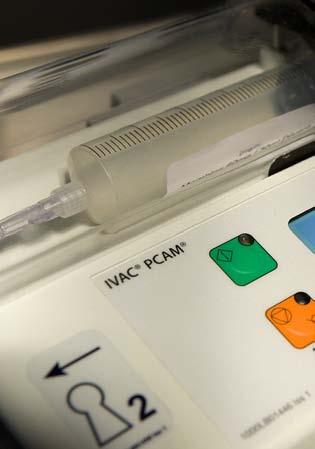
3 Introduction The IVC PCM Syringe Pump (herein after referred to as "pump") system allows a patient to maintain a consistent level of pain relief by providing self administration of a clinician-prescribed dose of analgesic as and when it is required. When the hand set is operated and the demand is within the parameters set by the clinician, the pump will automatically administer a precise bolus dose of analgesic. For enhanced monitoring and management of post operative acute pain within the hospital, the pump provides convenient Patient Controlled nalgesia (PC) and detailed information at the bed-side about the patients use of PC. Central to an effective pain service, the pump promotes improved pain management, more effective use of nursing resources, provides patient comfort and can contribute towards a quicker recovery. Intended Use: The pump is designed to meet the infusion requirements within the operating environment specified in this Directions For Use (DFU) including general wards, critical and intensive care, neonatal, operating rooms and accident and emergency rooms. This pump is suitable for use by appropriately trained clinicians or nurses. The pump is suitable to deliver fluids and medications via intravenous, epidural and subcutaneous routes. Supporting fluid therapy, blood transfusions and parenteral feeding. The pump is compatible with a wide range of standard, single-use, disposable Luer lock syringes. It accepts syringe sizes from 20 ml to 100 ml. See the 'Compatible Syringes' section for a full list of compatible syringes. User configured PC protocols. Comprehensive history. Large graphics format display. Two key positions providing separation of nursing and programming procedures. 10 pre-set hospital PC protocols. Unique electronic hand set with status indicator. Communications and nurse call interfaces. bout This Manual The user must be thoroughly familiar with the IVC PCM Syringe Pump described in this manual prior to use. ll illustrations used in this manual show typical settings and values which may be used in setting up the functions of the pump. These settings and values are for illustrative use only. Where stated, a minimum infusion rate refers to a nominal rate of 1.0ml/h, and an intermediate infusion rate refers to a nominal rate of 5.0ml/h. The complete range of infusion rates, settings and values are shown in the Specifications section. 1000DF00451 Issue 2 2/34
4 Features of the Pump LOCK 2 (on side of case) COVER STRT Display PURGE LOCK 1 STOP PLUS/MINUS RROW HISTORY PRINT Handset Connector RS232 Connector 1000DF00451 Issue 2 3/34
5 Controls & Indicators Controls: Symbol H X W J V R Q S Description STRT button - Press to start the infusion. The green LED will flash during infusion. STOP button - Press to put the infusion on hold. The amber LED will be lit while on hold. PURGE button - Press and hold both buttons to purge the extension set during set up. See 'Basic Features' for further information. HISTORY button - Press to display PC demands and drug infused history graphs, 24 hour review and event log. PRINT button - Press to print patient history. Note: suitable printer must be connected to the pump. PLUS/MINUS buttons - Use to move cursor and to increase or decrease values shown on main display. RROW buttons - Use as softkeys in conjunction with the prompts shown on the display. OFF SET RUN LOCK 1 - Insert key into LOCK 1 keyswitch and turn key to switch between OFF, SET and RUN positions. OFF - Turns the power off. SET - Use to select or modify protocols and to access configuration and test routines. RUN - Use to start the infusion. Note: Switching from RUN mode to SET mode without first pressing the STOP button automatically stops the infusion. LOCK 2 - Insert key into LOCK 2 and turn key clockwise to open the syringe cover. (This key lock is located on the left side of the pump) Indicators: Symbol j S Description BTTERY indicator - When illuminated the pump is running on the internal battery. When flashing the battery power is low with less than 30 minutes of use remaining. C POWER indicator - When illuminated the pump is connected to an C power supply and the battery is being charged. 1000DF00451 Issue 2 4/34
6 Symbol Definitions Labelling Symbols: Symbol Description wx yg k P r s T tu ttention (Consult accompanying documents) Potential Equalisation (PE) Connector RS232/Nurse call Connector (Optional) Class II Equipment Type CF applied part (Degree of protection against electrical shock) Protected against splashing fluid (degree of protection against fluid ingress) lternating Current Device complies with the requirements of Council Directive 93/42/EEC as amended by 2007/47/EC. Date of Manufacture Manufacturer Not for Municipal Waste Important information EC REP uthorised representative in the European Community 1000DF00451 Issue 2 5/34
7 Main Display Features Main Display Current Protocol Pump Status Volume Infused (Mass/Volume) Time PC Demand Status PC VILBLE DEMNDS TOTL GOOD IVC 50 ml 1 1 DRUG INFUSED 1.0 µg 0.1 ml PROTOCOL 13:07 Pumping Pressure Icon* Maximum Dose Icon* Syringe Type/Infusion Rate View Protocol Summary Protocol Summary Screen PROTOCOL MORPHINE 1.0 mg/ml PC DOSE 1.0 mg LOCKOUT 2 min CONTINUOUS 0 µg/h LODING 0 µg DOSE LIMIT 50.0 mg IN 4 h DOSE RTE STT QUIT * These icons are not displayed when disabled. Screen Icons: Symbol Description PUMPING PRESSURE icon - When enabled, this icon is shown on the Display. It provides a visual indicator of current pumping pressure and pressure level at which the alarm will operate. 4h MXIMUM DOSE icon - When enabled, this icon is shown on the Display. It provides a visual indication of the amount of drug administered during the limit period (as shown to the left of the icon). If the dose limit reaches the alarm level, the bottle icon will appear full, the pump will stop infusing and the message Max Dose Limit is displayed and the icon will flash until the dosing is less than the maximum dose limit. Clinician over-ride is always available. BCK icon - Indicates the softkey to press to go back to previous screen. 1000DF00451 Issue 2 6/34
8 Operating Precautions Disposable Syringes and Extension Sets m This pump has been calibrated for use with single-use disposable syringes. To ensure correct and accurate operation, only use 3 piece Luer lock versions of the syringe make specified on the pump or described in this manual. Use of non-specified syringes or extension sets may impair the operation of the pump and the accuracy of the infusion. n Uncontrolled flow or syphoning may result if the syringe is located incorrectly in the pump, or if it is removed from the pump before the extension set is properly isolated from the patient. Isolation may include closing a tap in the extension set or activating a flow stop clamp. G When combining several apparatus and/or instruments with extension sets and other tubing, for example via a 3-way tap, the performance of the pump may be impacted and should be monitored closely. Mounting the Pump Do not mount the pump in a vertical position with the syringe pointing upwards as this could lead to an infusion of air which may be in the syringe. To protect against the introduction of air the user should regularly monitor the progress of the infusion, syringe, extension set and patient connections and follow the priming procedure specified herein. Operating Environment When using any infusion pump in conjunction with other pumps or devices requiring vascular access, extra care is advised. dverse delivery of medication or fluids can be caused by the substantial variation in pressures created within the local vascular system by such pumps. Typical examples of those pumps are used during dialysis, bypass or cardiac assist applications. This pump is suitable for use in Hospital and clinical environments other than domestic establishments and those directly connected to the public single phase C mains power supply network that supplies buildings used for domestic purposes. However, it may be used in domestic establishments under the supervision of Medical professionals with additional necessary appropriate measures. (Consult Technical Service Manual, appropriately trained technical personnel or CareFusion for further information). This pump is not intended to be used in the presence of a flammable anaesthetic mixture with air or oxygen or nitrous oxide. Operating Pressure This is a positive pressure pump designed to achieve very accurate fluid administration by automatically compensating for resistance encountered in the infusion system. The pumping pressure alarm system is not designed to provide protection against, or detection of, IV complications which can occur. larm Conditions Several alarm conditions detected by this pump will stop the infusion and generate visual and audible alarms. Users must perform regular checks to ensure that the infusion is progressing correctly and no alarms are operating. 1000DF00451 Issue 2 7/34
9 Operating Precautions (continued) Electromagnetic Compatibility & Interference M This pump is protected against the effects of external interference, including high energy radio frequency emissions, magnetic fields and electrostatic discharge (for example, as generated by electrosurgical and cauterising equipment, large motors, portable radios, cellular telephones etc.) and is designed to remain safe when unreasonable levels of interference are encountered. Therapeutic Radiation Equipment: Do not use the pump in the vicinity of any Therapeutic Radiation Equipment. Levels of radiation generated by the radiation therapy equipment such as Linear ccelerator, may severely affect functioning of the pump. Please consult manufacturer s recommendations for safe distance and other precautionary requirements. For further information, please contact your local CareFusion representative. Magnetic Resonance Imaging (MRI): The pump contains ferromagnetic materials which are susceptible to interference with magnetic field generated by the MRI devices. Therefore, the pump is not considered an MRI compatible pump as such. If use of the pump within an MRI environment is unavoidable, then CareFusion highly recommends securing the pump at a safe distance from the magnetic field outside the identified Controlled ccess rea in order to evade any magnetic interference to the pump; or MRI image distortion. This safe distance should be established in accordance with the manufacturers recommendations regarding electromagnetic interference (EMI). For further information, please refer to the product technical service manual (TSM). lternatively, contact your local CareFusion representative for further guidance. ccessories: Do not use any non-recommended accessory with the pump. The pump is tested and compliant with the relevant EMC claims only with the recommended accessories. Use of any accessory, transducer or cable other than those specified by CareFusion may result in increased emissions or decreased pump immunity. This pump is a CISPR 11 Group 1 Class device and uses RF energy only for its internal function in the normal product offering. Therefore, its RF emissions are very low and are not likely to cause any interference with the nearby electronic equipment. However, this pump emits a certain level of electromagnetic radiation which is within the levels specified by IEC/EN and IEC/EN If the pump interacts with other equipment, measures should be taken to minimise the effects, for instance by repositioning or relocation. B In some circumstances the pump may be affected by an electrostatic discharge through air at levels close to or above 15kV; or by radio frequency radiation close to or above 10V/m. If the pump is affected by this external interference the pump will remain in a safe mode; the pump will duly stop the infusion and alert the user by generating a combination of visual and audible alarms. Should any encountered alarm condition persist even after user intervention, it is recommended to replace that particular pump and quarantine the pump for the attention of appropriately trained technical personnel. (Consult Technical Service Manual for further information). Hazards n explosion hazard exists if the pump is used in the presence of flammable anaesthetics. Exercise care to locate the pump away from any such hazardous sources. Dangerous Voltage: n electrical shock hazard exists if the pump s casing is opened or removed. Refer all servicing to qualified service personnel. V Do not open the RS232 protective covering when not in use. Electrostatic discharge (ESD) precautions are required when connecting RS232. Touching the pins of the connectors may result in ESD protection failure. It is recommended that all actions must be taken by appropriately trained personnel. If this pump is dropped, subjected to excessive moisture, fluid spillage, humidity or high temperature, or otherwise suspected to have been damaged, remove it from service for inspection by a qualified service engineer. When transporting or storing the pump, use original packaging where possible, and adhere to temperature, humidity and pressure ranges stated in the Specifications section and on the outer packaging. 1000DF00451 Issue 2 8/34

10 Getting Started Initial Set-up Before operating the pump read this Directions For Use manual carefully. 1. Check that the pump is complete, undamaged and that the voltage rating specified on the label is compatible with your C power supply. 2. Items supplied are: IVC PCM Syringe Pump User Support CD (Directions For Use) C Power Cable (as requested) Protective Packaging 3. Connect the pump to the C power supply for 24 hours to ensure that the internal battery is fully charged (verify that the S is lit). The Do pump will automatically operate from its internal battery if the pump is switched on without being connected to the C power supply. Prior to use on battery power, verify the pump continues to function on battery power once disconnected from the C power supply. Should the pump fail to perform correctly, replace in its original protective packaging, where possible and contact a qualified service engineer for investigation. not mount the pump with the C power inlet or the syringe pointing upwards. This could affect the electrical safety in the event of a fluid spill or lead to the infusion of air which may be in the syringe. Pole Clamp Installation The pole clamp is supplied fitted to the rear of the pump and will provide secure fixing to standard I.V. poles of a diameter of up to 40mm. The pole clamp can also be fitted in a choice of 4 fixing positions allowing the pump to be mounted to vertical and horizontal poles, equipment rails and hospital furniture in a variety of convenient operating orientations. The pole clamp may be adjusted for use with horizontal fittings by using the existing fixings screws with the alternative fixing holes in the pole clamp. The pole clamp may also be secured to the base of the pump in a choice of four positions. Patient Hand Set The patient hand set supplied with the pump is designed to be ambidextrous and suitable for both adult and paediatric use. The hand set provides an indicator light which clearly shows when the pump is available and can be configured to flash when a PC dose is being delivered. The indicator on the patient hand set will reflect the configuration of the pump and will provide feed-back on all, or just good demands, and the indicator light can be disabled should the clinical situation require. Where appropriate the hand set can be configured so that the patient will not need to refer to the instrument to assess if PC is being delivered, or is available. The hand set is provided with a clip for attaching it to bedding or clothing. The pump concept is that the patient can be instructed in the use of the hand set as it will carry all the information required by the patient using PC. This design simplifies patient instruction and encourages a smooth transfer to alternative devices used to treat long term chronic pain, should this be indicated. latching (but non locking) connector makes the hand set easy to fit. To remove, hold the body of the connector and pull away from the pump. n alarm warning will operate if the hand set is disconnected from the pump while it is in operation or the hand set is connected to the unit with the PC button depressed. In addition, the pump can be operated in continuous or clinician over-ride modes without the hand set connected, should this be required. 1000DF00451 Issue 2 9/34


11 Getting Started (continued) Warning: Loading a Syringe To securely load and confirm a syringe carefully follow the steps below. n incorrect loading of a syringe may result in misidentification of the syringe type and size. If then confirmed, this may lead to significant inaccuracy of the infusion rate and may also affect pump performance. Only use a syringe of the type stated on the pump or in this manual. Using an incorrect syringe could adversely affect the accuracy of the infusion and the performance of the pump. When initially loading the syringe, allow for the volume of fluid contained in the extension set and retained in the syringe at the end of infusion as this dead-space will not be infused. Place the pump on a stable horizontal surface or secure as described above. Prepare, load and prime the single-use disposable syringe and extension set using standard aseptic techniques. 1. Open the cover by turning key in Lock Squeeze the finger grips on the plunger holder and slide the mechanism to the left. Lift the syringe clamp and rotate clockwise. 3. Insert the syringe into the slots on the plunger holder. 4. Squeeze the finger grips on the plunger holder and slide the mechanism to the right until the syringe finger flanges locates in the V slot. Gently advance the syringe until the finger flanges touch the front of the V slot closest to the syringe clamp. This is important to prevent delay at the start of the infusion Rotate the syringe clamp anticlockwise until it locks onto the syringe barrel to secure the syringe. Check that the syringe plunger and finger flanges are correctly located in their slots. 7. Check that the syringe type and size being used matches display. If required, the make of syringe can be changed by pressing the CHNGE TYPE softkey. Press OK to confirm syringe. To minimise the risk of incorrect confirmation of the syringe type it is recommended that the default syringe type should be locked to only the one brand type used in the hospital where possible. Changing a Syringe during an infusion When changing the syringe LOCK 1 should remain in the RUN position except when a change is required to the protocol. 1. Press the X button to halt the infusion and place the pump on hold. 2. Open the cover using LOCK Close the extension line to the patient. 4. Change the syringe, fitting the new syringe as per instructions above. 5. Follow steps 7 to 10 of 'Starting the Pump' section on the next page. 1000DF00451 Issue 2 10/34
12 1. C POWER - Connect pump to C power supply using the C power cable. Note: the pump will operate on an internal battery when not connected to an C power source for a limited time. Getting Started (Continued) Starting the Pump Prior to beginning an infusion, disconnect the pump from the C power supply, confirm the pump continues to function on battery power. Then reconnect the pump to the C power source. 2. SET - Insert key into LOCK 1. Turn to SET position. 3. NEW PTIENT? - nswering NO will retain all previous patient history, except for the PC lockout time remaining which will be reset to PC VILBLE. YES will automatically reset the patient history to zero. Check time and date is correct and answer YES or NO. 4. SELECT/ MODIFY PROTOCOL - Carefully check the protocol displayed. If required, press MODIFY PROTOCOL to adjust the current protocol, or, NEXT PROTOCOL to select an alternative pre-set protocol. 5. RUN - Turn LOCK 1 to the RUN position and remove the key from pump. 6. CONFIRM PROTOCOL - Carefully check that protocol is correct. Press OK. 7. CONFIRM SYRINGE - Check that the syringe type and size being used matches display. If required, the make of syringe can be changed by pressing the CHNGE TYPE softkey. Press OK. 8. PURGE (if required) - The PURGE buttons can only be used when the cover is open and LOCK 1 is in the RUN position. When the purge operation is complete close the cover. 9. CONNECT PTIENT - Connect the PC extension set to the patient access device. Recheck the protocol. 10. STRT - Press the H button to commence pump operation. Either PC VILBLE or CONTINUOUS INFUSION will be displayed with the rate, demand and drug totals. If selected, a loading dose will be delivered. 11. PROTOCOL - Press PROTOCOL softkey at any time to display the protocol summary. To return to the main screen press QUIT. The pump will automatically operate from its internal battery if the pump is switched on without being connected to the C power supply. Each time the pump is switched ON, check that the alarm beeps twice and that all the segments of the display, the green and amber lights are illuminated during the self test routine. LOCK 1 should not be turned from OFF to SET whilst the syringe extension set is connected to the patient. 10 S R O BEGIN PC SIZE DF00451 Issue 2 11/34
13 Basic Features Purge The W button allows the delivery of a limited volume of fluid in order to purge the extension set prior to being connected to a patient. 1. PURGE can only be operated with the cover opened and LOCK 1 in the RUN position. 2. Press the W buttons together until fluid flows and priming of the syringe extension set is complete. The audible alarm will operate during use of the W buttons and the volume used during priming will be shown in the volume infused display. The PURGE feature is not activated when the cover is closed. Ensure that the extension set is disconnected from the patient before purging the line. No alarms are disabled during the operation of the PURGE feature. During PURGE the pressure limit alarms are temporarily increased to their maximum level. Clinician Over-ride The clinician over-ride feature can be used in RUN mode to administer an additional bolus dose or continuous background infusion of a limited dose and duration, for example during the PC lock out period. The clinician over-ride is a special feature which can be configured according to the specific clinical situation. Clinician over-ride can also be used in SET mode to allow modification of the pre-set PC Protocol when this option has been disabled for normal use. 1. Turn LOCK 1 to RUN position and ensure green light is illuminated on the H button. 2. Press and hold down the T button for 2 seconds. 3. Use R Q buttons and NEXT softkey to enter three figure pre-programmed clinician access code. See technical service manual. 4. Select BOLUS or CONTINUOUS. 5. Use R Q buttons to select the dose delivered, when the correct value has been entered press OK. 6. Use R Q buttons to select period over which the dose is to be delivered. Press OK when correct time has been entered. 7. BEGIN BOLUS? YES - Clinician bolus / continuous infusion will be delivered to the patient. NO - Quit set up and return to normal operation. The delivery of the clinician over-ride continuous infusion will automatically halt while a Patient or Clinician over-ride bolus is being administrated. To cancel clinician over-ride during delivery, press I button and press the YES softkey. During BOLUS the pressure limit alarms are temporarily increased to their maximum level. 1000DF00451 Issue 2 12/34

 history still held in memory.")

14 Basic Features (Continued) Patient History Each time the pump is switched ON it will ask if this is a new patient. Pressing YES will provide opportunity to re-set patient history. Pressing NO continues with the current protocol and retains all protocol records, event history, graphs etc. However, any remaining PC lockout time will be cleared and a PC demand will be immediately available. The pump will retain the events in a rolling memory. Following selection of a new patient, it remains possible in technician mode to access previous patient(s) history still held in memory. Patient history can be accessed at any time by pressing the J button. The pump provides a clear rolling 24 hour graphical representation of the PC demand pattern and the drug administered to the patient. The graphs are updated when the history button is pressed and give values for each completed hour and the current hour. The cumulative counters on the Drug Infused history screen update in real-time. 24 Hour Review n hour by hour record of the last 24 hours, showing good and total PC demands along with the total dose and volume per hour. This information provides the accurate demand pattern and drug infused values from which the other graphs are derived. 1. To access the 24 Hour Review press the J button once. 2. To return to the previous screen press the BCK softkey. 3. To scroll through to the next History screen press the J button. PC Demands Provides a record of the last 24 hours good and failed PC demands. The good demands are indicated by the shaded section of the graph and the failed demands by the clear section. The latest hour is shown at the right side of the display. This graph provides a clear picture of good and bad PC demands and pattern of the patients usage. Used in conjunction with the PC Demands graph, this display helps to indicate if the PC protocol needs modification and when to end treatment. 1. To access the PC demand graph press the J button twice. 2. To exit the screen press the BCK softkey. 3. To scroll through to the next History screen press the J button. Drug Infused Record of the total amount of drug administered to the patient over the last 24 hours. The latest hour is shown at the right side of the display. This graph provides a clear picture of the actual drug administered, including loading dose, continuous background infusions, clinician over-rides and protocol changes. The left side of the display shows cumulative dose and time counters with the time, mass and volume infused since the patient session started or since the counters were last reset. To reset counters press CLER and then CONFIRM. Used in conjunction with the PC Demands graph, this display helps to indicate relative pattern of the demand pattern and the actual drug administered. 1. To access the Drug Infused graph press the J button three times. 2. To return to the previous screen press the BCK softkey. 3. To scroll through to the next History screen press the J button. 1000DF00451 Issue 2 13/34
15 Basic Features (Continued) Event Log Record of events since "NEW PTIENT" selected. Including, protocol selection and changes, patient demands etc. The event log will also record all alarms. ll events are recorded against date, clock and total drug infused. 1. To access the Event Log press the J button four times. 2. To return to the previous screen press the BCK softkey. 3. To return to the Protocol Summary press the J button again. Printing printer fitted with a serial interface (or cable with parallel to serial converter) can be connected to the pump, either during normal PC operation or following use. Printing patient history provides a permanent record and can be used for analysis away from the bedside. ll patient history, including protocols and the 24 hour demand pattern and drug dose administered graphs are available for printing. When connected to the printer, the pump can also be configured to provide line by line continuous printing of all events, patient demands etc. as they occur at the bedside. See General Options. Print Connect Printer then... Information printed Protocol Summary Turn LOCK 1 to SET position Press V button ll protocol information will be printed with patient header. Patient History Press V button ll protocol information, demand and drug totals, 24 hour graphs and records will be printed with patient header. Event Log Press J button until event log is displayed. ll events will be printed from information on screen forward with time, date and patient header. Use S buttons to position display at start point for events to be printed. Press V button Event Log at New Patient Press V button ll events will be printed from the patient event log. Enable Continuous printing by selecting YES in General Options. 1. Connect printer. 2. ll events will be printed as they occur. Continuous Mode Teach Learn Mode By programming the configuration of one pump in the conventional way from the front panel buttons other pumps can have the configuration copied over using the teach and learn modes. When set to learn mode the pump will accept information sets from a pre-configured pump set to teach mode. When set to teach mode the pump sends out via the communications interface a sequence of all the information sets required to configure another pump. To fully configure a pump it is necessary to send 22 complete information sets as described in the protocols and the full cycle takes about 22 seconds. The two pumps must be connected together using an RS232 Demonstration Cable. Both pumps must be of the same version software and revision and set to a common pump comms identification number (see General Options). The configured pump is set to teach mode and the pump to be configured is set to learn mode using the access codes listed in the Technical Service Manual. The pump in learn mode will display PSS or FIL for each information set being received from the teach mode device. The pumps must run through at least one complete sequence of the information sets and then switch off first the learn pump and then the teach pump. fter using this method it is the user s responsibility to check that the configuration has been copied over correctly. 1000DF00451 Issue 2 14/34
16 Basic Features (Continued) Pre-Set PC Protocols Operation of the pump is greatly simplified by the use of PRE-SET PC protocols. When LOCK 1 is turned to the SET position the pump will automatically display pre-set PROTOCOL if NEW PTIENT has been selected or display the previous protocol in use if NEW PTIENT has not been selected. With LOCK 1 in the SET position, it is possible for the user to modify the pre-set protocol using the MODIFY PROTOCOL button and select another pre-set protocol using the NEXT PROTOCOL button. To modify a Pre-Set Protocol 1. Press MODIFY PROTOCOL indicated on the screen. 2. The protocol summary will be displayed. Use S buttons to highlight a field, press LTER to enter that field and R Q buttons to select desired values. 3. When field is correct press CONFIRM or CNCEL. 4. Display will show: Protocol Drug name Drug X Drug conc. 1.0mg/ml PC Dose 1.0mg (1.0ml) Lockout period 5 mins Occlusion level 4 Continuous 0µg/h (0.0ml/h) Loading dose 0µg (0.0ml) Max. limit 50mg (50.0ml) Limit duration 4 hours PC delivery STT 5. Press OK to return to display. PROTOCOL SUMMRY PC Dose 1.0 ml MX 50.0ml IN 4h DRUG X 1.0mg/ml Lockout 5 mins MODIFY PROTOCOL Continuous 2.0ml/h Loading 2.0 ml NEXT PROTOCOL Notes: modified protocol has no pre-set letter. To utilise this function, MODIFY PROTOCOL must be enabled in GENERL OPTIONS. To change to another Pre-Set Protocol Press NEXT PROTOCOL to display the step through the pre-set protocol. Pre-set protocols are identified as to J. When the desired protocol has been selected it can be used by turning LOCK 1 to the RUN position, or, can be modified using the MODIFY PROTOCOL. To confirm a Protocol Whenever a new protocol is selected, modified or LOCK 1 is turned to the SET position, the CONFIRM PROTOCOL display will appear. Pressing OK automatically records the protocol and any changes in the EVENT LOG history. Volumes and rates are typically calculated to more decimal places than are displayed. To achieve this, the values are rounded down to prevent the impression of an over-infusion. The doses and dose rates are calculated from the volume of rate that the pump infuses. Thus, when configuring protocols some combinations of drug concentration and PC dose may result in the displayed rate and the dose rate appearing inconsistent or the displayed dose appearing incorrect. See examples on next page. 1000DF00451 Issue 2 15/34
17 Example 1. Displayed rate and dose rate appear inconsistent. Dose rate = 30µg/h Drug Concentration = 44µg/ml Basic Features (Continued) Pre-Set PC Protocols (continued) This would give a rate of ml/h. The pump would round the calculation to two decimal places, giving an actual infusion rate of 0.68ml/h, whilst the screen will display a rate of 0.6ml/h and a dose rate of 29µg/h. Example 2. Displayed dose does not appear correct. PC Dose = 720µg Drug Concentration = 500µg/ml For each PC demand the pump would infuse ml. For the purpose of the displayed volume, the first PC demand is counted as 1.43ml (715µg) with the remaining ml being carried over into the display of the next demand. The next demand would be displayed (accumulatively) as 2.87ml (1.4399ml ml = ml) with the remaining ml being carried over into the display of the next demand. For the purpose of the displayed dose, the first PC demand is calculated as 715µg (drug concentration 500µg/ml multiplied by calculated dose 1.43ml). The next demand would be displayed (accumulatively) as 1.43mg (500µg/ml multiplied by calculated dose 2.87ml = 1435µg = 1.435mg which is rounded down and displayed to two decimal places = 1.43mg). If similar inconsistencies are experienced, contact your local CareFusion representative for clarification. 1000DF00451 Issue 2 16/34
18 larms larms are indicated by a combination of an audible alarm, flashing amber STOP light and a descriptive message in the display. 1. First press the MUTE softkey to silence the alarm for a maximum of 2 minutes, then check the display for an alarm message. Press X to cancel the alarm message. 2. If the infusion has stopped, rectify the cause of the alarm then press the H button to resume the infusion. Message DRIVE DISENGGED COVER OPENED LINE OCCLUSION SYRINGE ERROR CHECK HNDSET BTTERY LOW BTTERY EXHUSTED SYRINGE NER EMPTY SYRINGE EMPTY C POWER FIL MLFUNCTION MX DOSE EXCEEDED 3 BEEPS (larm without screen prompt) Cause and Troubleshooting Guide PUMP DRIVE DISENGGED The drive system has been disengaged during operation. Use LOCK 2 to unlock and open the cover. Check the finger grips and the position of the syringe. COVER OPENED DURING OPERTION The cover has been opened during operation. Check cover and LOCK 2. EXCESSIVE PUMPING PRESSURE Pumping pressure has reached the alarm limit. Use LOCK 2 to unlock and open the cover, squeeze finger grips on the plunger holder to release the drive mechanism and relieve any excessive pressure in the syringe and patient line. Identify and remove the cause of the blockage in the drive, syringe, or administration system before restarting the infusion. SYRINGE SIZE ERROR / FITTED INCORRECTLY Incorrect size of syringe has been fitted, the syringe clamp has not been positioned correctly on the syringe or has been disturbed during operation or plunger is not fitted in plunger slot. Use LOCK 2 to unlock and open the cover, check syringe size, position of syringe clamp, syringe and plunger. PTIENT HND SET FILURE Patient hand set has become faulty or disconnected during operation. Check operation and connection of the hand set to the pump. Press H to continue if operation without the hand set is required. BTTERY CHRGE LOW WRNING Battery charge low with 30 minutes operation remaining. Battery indicator will flash and after 30 minutes a continuous audible alarm will indicate that the battery is exhausted. Reconnect to C power supply to continue operation and charge internal battery. BTTERY EXHUSTED Internal battery exhausted. To silence the alarm switch LOCK 1 to the OFF position and reconnect pump to C power supply. Restart operation on C power whilst charging the internal battery. Switch to the RUN position. NER END OF SYRINGE WRNING Syringe almost empty with about 6% of its volume remaining. Press H to silence alarm and continue operation. Display will flash SYRINGE NER EMPTY. The alarm screen will also flash USE LOCK 2 TO OPEN COVER. SYRINGE EMPTY - END OF INFUSION The pump has reached the end of the infusion. bout 1% of the syringe volume will remain in the syringe helping to prevent the infusion of air bubbles into the PC set. The alarm screen will flash USE LOCK 2 TO OPEN COVER. C POWER SUPPLY DISCONNECTED WRNING C Power has been disconnected and the pump is operating on battery power. Reconnect C power supply or press X to silence the alarm and continue battery operation. The display will light up ON BTTERY. The alarm will automatically cancel if the C power supply is reconnected. INTERNL MLFUNCTION The alarm system has detected an internal malfunction. Note the malfunction code. Remove pump from service for examination by a qualified service engineer. MX DOSE LIMIT The maximum dose over time limit has been exceeded. Infusion is stopped when the alarm occurs. Press X to cancel the alarm. The max dose icon will flash until dosing is less than the maximum dose limit. Note that this alarm can be disabled under General Options. NURSE TTENTION WRNING Pump left switched ON for more than 2 minutes without starting operation. Press X or any of the control buttons to silence the alarm for a further 2 minutes. To cancel this alarm for 15 minutes, press and hold the X button until 3 rapid, consecutive beeps are heard. 1000DF00451 Issue 2 17/34
19 Configured Options This menu comprises a list of options which are configurable by the user. 1. Whilst holding down the H button turn the pump ON. 2. The main display will show 000. Enter the access code for Configured Options using the R Q buttons, pressing NEXT to move through the digits. full list of access codes can be found in the Technical Service Manual. 3. When the complete code shows on screen, press ENTER. The Configured Options menu will be displayed. General Options 1. Select GENERL OPTIONS from the menu using the R Q buttons and press ENTER. 2. Select the option you wish to enable/disable or adjust and press MODIFY. 3. When all the desired modifications have been carried out press QUIT. 4. Either select the next configuration option from the menu or turn the pump OFF, returning it to operation as required. Option Description 1. ICONS on display YES - displays Pumping Pressure and Maximum Dose ICONS. NO - ICONS disabled. 2. Protocols in use PC pre-set protocols to be available. Select number from 1 to Modify protocol YES - allows protocols to be modified in SET mode. NO - removes modify protocol option in SET mode. 4. Handset mode MODE B C BEEP GOOD LL LL HND SET LIGHT: PCM STOPPED OFF OFF OFF PC VILBLE ON ON ON PC DELIVERING FLSH ON FLSH PC LOCK-OUT OFF ON ON 5. Delayed call-back YES - call-back alarm can be delayed from 10 mins up to 90 mins. NO - call-back will be cancelled for up to 2 mins or extended to 15 mins. To extend call-back alarms, press and hold the X button for 4 seconds. 6. Display Sleep YES - display goes blank after 2 minutes. NO - display stays on during operation. 7. Chirp low alarms YES - chirp alarm during use on battery/near end. NO - no chirp alarm. 8. Continuous infusions YES - Continuous infusions option in protocols. NO - Continuous infusions are not available. 9. Loading doses YES - Loading dose option appears in protocols. To activate this option NEW PTIENT is confirmed. The protocol also includes the loading dose. Start the PC. NO - Loading doses are not available. 10. Max. dose limits YES - Dose limit option appears in protocols. NO - Dose limits are not available. 11. Variable dose rates YES - llows the dose rate to be varied, when modifying the protocol. Dose rate can be either STT rate (100ml/h max.) or the dose can be delivered over a period of time from 1 to 60 minutes. NO - Each dose will be delivered at the STT rate and there is no option to change when modifying the protocol. 12. Comms identity number Use R Q buttons to set pump identity (between 000 and 127) for use with remote communications. 13. Comms enabled YES - RS232 Communications enabled. NO - RS232 Communications disabled. 14. Nurse call YES - Nurse call connector enabled. NO - Nurse call connector disabled. 15. Nurse call inverted YES - Nurse call inverted enabled. NO - Nurse call inverted disabled 1000DF00451 Issue 2 18/34
20 Configured Options (Continued) General Options (continued) Option Description 16. Continuous Print YES - llows printing of events as they happen. NO - Continuous printing disabled. 17. Default Syringe Use R Q buttons to select the default syringe brand. 18. Lock syringe type YES - Syringe type locked to default syringe. NO - Syringe type not locked to default syringe. 19. Quiet mode YES - Quiet mode enabled. NO - Quiet mode disabled. 20. Generic Drug Enabled YES - llows Protocols to be set up to use a Generic Drug, which is preset to maximum safety limits. NO - Disallows use of Generic Drug. 21. Max Dose Limit larm YES - larm is generated when max dose limit is reached. NO - larm is not generated when max dose limit is reached. 22. Mix Mass & Vol Modes YES - llow a mix of mass and volume dose mode for drugs and protocols. NO - ll drugs and protocols use mass dose mode. To minimise the risk of incorrect confirmation of the syringe type it is recommended that the default syringe type should be locked to only the one brand type used in the hospital where possible. Clock Set 1. Select CLOCK SET from the Configured Options menu and press ENTER. 2. Use the R Q buttons to adjust the date and time displayed, pressing NEXT to access the next field. 3. When the correct time and date are displayed press OK to return to the Configured Options menu. The internal clock is the reference against which the pump stores patient history and events. Changing the clock will automatically reset the dates against which all new patient history is stored in the pump. fter changing the clock, the pump will force a YES response the next time the NEW PTIENT screen appears. This will clear the patient history. Therefore, patient history should always be recorded and, if required, printed prior to changing the clock. Pre-Set Protocol Set-Up 1. Select PROTOCOL DEFULT SET-UP from the Configured Options menu and press ENTER. 2. Press MODIFY PROTOCOL to display current protocol summary. Use the R Q buttons to highlight a field, press LTER to access the field and the R Q buttons to select required values. 3. When the field is correct press CONFIRM. Press OK to return to the protocol summary. One of the ten drugs programmed in the Drug Names and Safety Limits are selectable for each protocol. dditionally a default drug with limits set to extremes may be chosen if Generic Drug is enabled in General Options. Default drugs are named MSS DRUG and VOL DRUG. The names indicate the underlying dose mode. Hospital Name This option allows the user to programme in the name of the hospital, ward or department. This will appear during the power-up display sequence and the 'Display Sleep' screen (if enabled in General Options). 1. Whilst holding down the H button turn the pump ON. 2. The main display will show 000. Enter the access code for Hospital Name using the R Q buttons, pressing NEXT to move through the digits. full list of access codes can be found in the Technical Service Manual. 3. When the complete code shows on screen, press ENTER. The Hospital Name Option will be displayed. 4. Use the R Q buttons to adjust the character displayed, pressing NEXT to access the next position. 5. When the correct name is displayed turn LOCK 1 to the the off position. 1000DF00451 Issue 2 19/34
21 Configured Options (Continued) Drug Names and Safety Limits If enabled in General Options, a drug can be configured in either Mass or Volume dosing mode. If this option is disabled, all drugs and protocols are computed in dose units of mass. On all drug parameter screens except DRUG name, press back to return to the previous parameter. 1. Turn LOCK 1 to SET position while pressing down H button. 2. Enter the access code using the R Q buttons. 3. Select DRUG NMES ND SFETY LIMITS from the menu. Press ENTER. 4. Press MODIFY DRUG to modify the drug summary. Use R Q buttons to select desired values. When field is correct press OK to store the selection. 5. NME: Use R Q buttons to set highlighted letter. Press NEXT for next character (up to twelve letters). Press OK when complete. 6. DOSE MODE: Use R Q buttons to change dose mode. Changing dose mode resets Drug parameters to defaults and also resets Protocols that use this drug. To change dose mode, press CONFIRM. Press OK when complete. Note: Dose Mode will not be displayed if Mix Mass & Volume Modes is disabled in General Options. 7. MIN DRUG CONC: Use R Q buttons to set minimum concentration. For volume mode, concentration can be set to OFF, the lowest value. Press OK when complete. 8. MX DRUG CONC: Use R Q buttons to set maximum concentration. Press OK when complete. If min Drug conc is set to OFF, this parameter does not appear. 9. MIN LOCKOUT PERIOD: Use R Q buttons to set minimum lockout period. Press OK when complete. 10. MX LOCKOUT PERIOD: Use R Q buttons to set maximum lockout period. Press OK when complete. 11. MIN PC DOSE: Use R Q buttons to set minimum PC dose. Press OK when complete. 12. MX PC DOSE: Use R Q buttons to set maximum PC dose. Press OK when complete. 13. MX CONTINUOUS: Use R Q buttons to set maximum continuous rate. Press OK when complete. 14. MX LODING DOSE: Use R Q buttons to set maximum loading dose. Press OK when complete. 15. MX DOSE LIMIT: Use R Q buttons to set maximum dose limit. Press OK when complete. 16. MX CLINICIN BOLUS: Use R Q buttons to set the maximum clinician bolus. Press OK when complete. 17. NEXT DRUG to display the next drug name and the safety limits. The ten pre-set drug protocols are identified as 1 to Press QUIT to exit and return to configuration menu. 19. When set-up is complete, turn LOCK 1 to OFF position to save selection and to turn pump off. 1000DF00451 Issue 2 20/34
22 General Options Configured Options Record Enter the pump-specific information for your records on a copy of this page. Option Range Default Setting ICONS ON DISPLY YES/NO NO PROTOCOLS IN USE MODIFY PROTOCOL YES/NO YES HNDSET MODE / B / C DELYED CLLBCK YES/NO YES DISPLY SLEEP YES/NO YES CHIRP LOW LRMS YES/NO NO CONTINUOUS INFUSIONS YES/NO YES LODING DOSES YES/NO YES MX DOSE LIMITS YES/NO YES VRIBLE DOSE RTES YES/NO YES COMMS PUMP IDENTITY COMMS ENBLED YES/NO YES NURSE CLL YES/NO NO NURSE CLL INVERTED YES/NO NO CONTINUOUS PRINT YES/NO NO DEFULT SYRINGE BD PLSTIPK IVC TERUMO B. BRUN OMNIFIX MONOJECT R.R PRONTO BD WORLDWIDE ONCE FRESENIOUS INJECT. RPIJECT PHRM-JECT BD PRECISE BRUN PERFUSOR* JNPOL* * with options kit fitted BD PLSTIPK LOCK SYRINGE TYPE YES/NO NO QUIET MODE YES/NO NO GENERIC DRUG ENBLED YES/NO YES MX DOSE LIMIT LRM YES/NO YES MIX MSS & VOL MODES YES/NO NO Syringe Type UNIVERSL BRUN PERFUSOR JNPOL Enabled Hospital Name Serial No. Software Version pproved by Date Configured by Date 1000DF00451 Issue 2 21/34
23 Drugs and Protocols Record Drugs and Protocols Record Enter the pump-specific information for your records Hospital/Institution: Drug names and Safety Limits Department/Ward: Drug number Mass Range Volume Range Drug Name (12 characters) Dose Mode Mass Volume Minimum Drug Concentration 1µg/ml mg/m Off, 1µg/ml mg/ml Maximum Drug Concentration 1µg/ml mg/ml 1µg/ml mg/ml Minimum Lockout Period minutes minutes Maximum Lockout Period minutes minutes Minimum PC Dose 0µg mg 0.0ml ml Maximum PC Dose 0µg mg 0.0ml ml Maximum Continuous 0µg/h mg/h 0.0ml/h - 35ml/h Maximum Loading Dose 0µg mg 0.0ml - 99ml Maximum Max Limit 0µg - 999mg 0.0ml - 999ml Maximum Clinician Bolus 1µg mg 0.1ml ml Protocol Default Set Up Protocol number B C D E F G H I J Drug Name Drug Concentration PC Dose Lockout Period Occlusion Level Continuous Loading Dose Max Limit Limit Duration PC Delivery Model: Serial Number: Configured by: Date: Software Version: pproved by: Date: 1000DF00451 Issue 2 22/34
24 Specifications CONCENTRTION RNGE: 1µg/ml - 999µg/ml in 1µg/ml steps 1.0mg/ml mg/ml in 0.1mg/ml steps VOLUME MODE: Concentration can also be set OFF, in which case no mass data is displayed. PC DOSE RNGE: Mass Mode: 0.0µg µg in 1µg steps 1mg mg in 0.1mg steps Volume Mode: 0.0ml ml in 0.1ml steps PC DELIVERY RTE: 100ml/h max. STT rate for 30ml, 50ml and 100ml syringes and 80ml/h for 20ml syringes. (Option to set duration from 1 to 60 mins in 1 min steps to minimum rate of 0.1ml/h and maximum of the STT rate). RTE CONVERSION FCTOR: When pump is programmed in Mass units the conversion factor is:- ml/h = (dose/concentration)/(time in minutes/60). LOCKOUT INTERVL: minutes in 1 minute steps LODING DOSE RNGE: Mass Mode: 0µg - 999µg in 1µg steps 0.0mg mg in 0.1mg steps (Delivered at STT rate) Volume Mode: 0.0ml ml in 0.1ml steps CONTINUOUS RTE RNGE: Mass Mode: 0µg/h - 90µg/h in 10µg/h steps 0.0mg/h mg/h in 0.1mg/h steps Volume Mode: 0.0ml/h ml/h in 0.1ml/h steps. MX DOSE LIMIT: Mass Mode: off, 1µg - 999µg in 1µg steps 1mg - 999mg in 1mg steps Volume Mode: off, 0.1ml to 999ml in 0.1ml steps 1-8 hours duration in 1 hour steps. PURGE RTE: 100ml/h SYSTEM CCURCY: Drive Linearity: +/- 1% Bolus: +/- 0.05ml Volumetric: +/- 2% (nominal) (Volumetric accuracy is +/-2% typical by volume at the STT PC rate and above when the pump is used with the recommended syringes. Differences in factors such as size and plunger force in compatible syringes can cause variations in accuracy and trumpet curves.) Important: System accuracy is +/-2% typical by volume as measured using the trumpet curve test method defined in EN :1998 at rates of 1.0ml/h and above when the pump is used with the recommended syringes. Differences in factors such as size and plunger force in compatible syringes can cause variations in accuracy and trumpet curves. lso see trumpet curves section. Environmental Specifications - Operating Temperature +10 C C Operating Relative Humidity 30% - 75% Operating tmospheric Pressure 700hPa hPa Transport & Storage Temperature -20 C C Transport & Storage Relative Humidity 5% - 95% Transport & Storage tmospheric Pressure 600hPa hPa OPERTION MODE: Continuous CRITICL VOLUME: The maximum over infusion which can occur in the event of a single fault condition is 0.8ml for 20ml, 30ml and 50ml syringes and 1.5ml for a 100ml syringe. LRM CONDITIONS: Pressure Limit exceeded Low Battery Warning Drive Disengaged Battery Exhausted Syringe lmost Empty Cover Open during operation Syringe Empty Hand-set Disconnected Max Dose Limit (optionally alarmed) Internal Malfunction Nurse ttention/call Back Syringe Error PUMPING PRESSURE / LRM LEVEL: 375mmHg (nominal) default alarm level (L-4) with 11 user selectable alarm levels (L-0 to L-10). Syringes may limit below level 10. (The maximum pressure that can be developed by the system at the maximum user selectable alarm level is 1100mmHg). CLINICIN OVER-RIDE: Bolus or continuous infusion in RUN mode. (User selectable from 1µg mg or 0.1ml to 99.9ml (volume mode) bolus dose administered at the STT rate (100ml/h) or over 1 to 180 minutes delivery period). Modify PC Protocol in SET mode. (When option to disable MODIFY PROTOCOL has been selected). BTTERY OPERTION: 6 hours operation from a fully charged battery at 5.0ml/h and 20 C under normal conditions. BTTERY TYPE ND RECHRGE TIME: Rechargeable sealed lead acid type. 10 hours from discharge to 80% charge, 24 hours from discharge to 100% charge. EVENT HISTORY: 2000 events rolling memory. MEMORY RETENTION: ll calibration and set up information will be retained in the pump memory for a minimum of 3 years. BOLUS VOLUME CCURCY: The following table provides an indication of the accuracy with which a bolus infusion will be delivered. Test carried out as specified in IEC/EN Bolus Volume (ml) Bolus Rate (ml/h) No. of Samples Max. Positive (%) Max. Negative (%) Mean (%) DF00451 Issue 2 23/34
Alaris CC Syringe Pump
 Alaris CC Syringe Pump Models: 80033GBxx, 80033UNxx Directions For Use en s Contents Page Introduction...2 About This Manual...2 Quick Start Guide...2 Features of the Alaris CC Syringe Pump...3 Controls
Alaris GP Volumetric Pump. Directions For Use en
 laris GP Volumetric Pump s Directions For Use en Contents Page Introduction...2 bout this Manual...2 Creating a Data Set...3 Features of the laris GP Volumetric Pump...4 Controls and Indicators...5 Symbol
Contents. 6. Infusion Mode...10
 Contents 1. General Description 2 1.1 Features and product purpose 2 2. Principle of Operation....2 3. Specification.2 4. Front View 5 5. Basic Setting.6 5.1 Installation.6 5.2 Power On 6 5.3 Time Setting...7
Alaris TIVA Syringe Pump
 Alaris TIVA Syringe Pump Model: 80043UNxx Directions For Use en s Contents Page Introduction...2 About This Manual...2 Quick Start Guide...2 Features of the Alaris TIVA Syringe Pump...3 Controls & Indicators...4
6800 Maintenance Instruction System Flush Procedure
 Equipment Required FA74005 FA65318 FA900005 FA900003 Damper Drain Tube 6800 Cover Removal Tool Beaker 0.25 Litre Solvent Cleaning Bottle FA940021 Syringe Polypropylene 50 ml as required FA999045 Gloves
BODYGUARD 2CH TWIN CHANNEL INFUSION PUMP
 BODYGUARD 2CH TWIN CHANNEL INFUSION PUMP The BodyGuard 2CH Twin Channel Infusion Pump is an ambulatory multi-therapy pump suitable for hospital and homecare environments with five infusion programs (continuous,
Alaris GH Syringe Pump
 Alaris GH Syringe Pump Models: 80023xx01, 80023xx00 Directions For Use en s Contents Page Introduction...2 About This Manual...2 Quick Start Guide...2 Features of the Alaris GH Syringe Pump...3 Controls
Alaris Syringe Pump (with Plus Software) MK3
 MK3") Alaris Syringe Pump (ith Plus Softare) MK3 Models: 8002MED01, 8002MED01-G, 8003MED01, 8003MED01-G Directions For Use en s Contents Alaris Syringe Pumps Introduction.... 2 About This Manual.... 3 Creating
Alaris Syringe Pump (ith Plus Softare) MK3 Models: 8002MED01, 8002MED01-G, 8003MED01, 8003MED01-G Directions For Use en s Contents Alaris Syringe Pumps Introduction.... 2 About This Manual.... 3 Creating
Alaris GH Guardrails Syringe Pump
 Alaris GH Guardrails Syringe Pump Models: 80023UNxx-G, 80023NWxx-G Directions For Use en s Contents Page Introduction...2 About This Manual...2 Creating a Data Set...3 Features of the Alaris GH Guardrails
6900 Maintenance Instruction System Flush
 Equipment Required FA74005 Damper Drain Tube FA16005 Cover Removal Tool FA900005 Beaker 0.25 Litre FA900003 Solvent Cleaning Bottle FA940021 Syringe Polypropylene 50 ml as required FA999045 Gloves Latex
Nimbus II PainPRO Ambulatory Infusion Pump
 Nimbus II PainPRO Ambulatory Infusion Pump Patient Manual PCA Mode Infusions Read this entire manual prior to operating the Nimbus II PainPRO Ambulatory Infusion Table of Contents Section 1: General Description...
SomnoSuite FAQ. Setup. Calibration 4. What are the calibration requirements for the SomnoSuite? Settings
 SomnoSuite FAQ V1.3 January 2015 Setup 1. How do I connect the SomnoSuite to my oxygen source? 2. Is there a way to speed up the downward movement of the pusher block when setting the empty position? 3.
Nimbus II PainPRO Ambulatory Infusion Pump
 Nimbus II PainPRO Ambulatory Infusion Pump Patient Manual PCA Mode Infusions Read this entire manual prior to operating the Nimbus II PainPRO Ambulatory Infusion Table of Contents Section 1: General Description...
AQUADEX FLEXFLOW SYSTEM QUICK REFERENCE GUIDE
 AQUADEX FLEXFLOW SYSTEM QUICK REFERENCE GUIDE AQUADEX FLEXFLOW SYSTEM DISCLAIMER The quick reference guide is not intended to replace CHF Solutions, Inc. Aquadex FlexFlow Direction For Use (DFU). Always
ASE SOLVENT CONTROLLER INSTALLATION INSTRUCTIONS Dionex Corporation
 ASE SOLVENT CONTROLLER INSTALLATION INSTRUCTIONS 2000 Dionex Corporation Document No. 031277 Revision 03 April 2000 2000 Dionex Corporation All rights reserved worldwide. Printed in the United States of
CADD-Micro. Model 5900 Operator s Manual. Note: Colors are Black and Cyan (as second color) Deltec. Ambulatory Infusion Pump
 Deltec. Ambulatory Infusion Pump") Note: Colors are Black and Cyan (as second color) CADD-Micro Ambulatory Infusion Pump Overview Programming Examples Model 5900 Operator s Manual Deltec SIMS Deltec, Inc., St. Paul, MN 55112 U.S.A. 87 Overview
Note: Colors are Black and Cyan (as second color) CADD-Micro Ambulatory Infusion Pump Overview Programming Examples Model 5900 Operator s Manual Deltec SIMS Deltec, Inc., St. Paul, MN 55112 U.S.A. 87 Overview
Calibration Gas Instrument INSTRUCTION MANUAL. Release I. Advanced Calibration Designs, Inc.
 Advanced Calibration Designs, Inc. Calibration Gas Instrument INSTRUCTION MANUAL Release I www.goacd.com Instruction Manual Gas Generator Release I TABLE OF CONTENTS I. General Description Page 2 II. Start-Up
Pegas 4000 MF Gas Mixer InstructionManual Columbus Instruments
 Pegas 4000 MF Gas Mixer InstructionManual Contents I Table of Contents Foreword Part I Introduction 1 2 1 System overview... 2 2 Specifications... 3 Part II Installation 4 1 Rear panel connections...
BOC: Living healthcare. Manual. LIV IQ BOC Integrated Valve with digital display portable delivery system for Medical Oxygen. BOC: Living healthcare
 BOC: Living healthcare Manual LIV IQ BOC Integrated Valve with digital display portable delivery system for Medical Oxygen. BOC: Living healthcare 02 Manual LIV IQ Oxygen Manual LIV IQ Oxygen 03 Contents.
ECHO MANUAL WARNING. L B A ltim e te rs. ECHO is a trademark of LB Altimeters, Denmark
 ECHO MANUAL L B A ltim e te rs ECHO is a trademark of LB Altimeters, Denmark LB Altimeters operates a policy of continuous development Therefore, we reserve the right to make changes and improvements to
Alaris PK Syringe Pump. Directions For Use EN
 laris PK Syringe Pump s Directions For Use EN Contents Page Introduction.............................................................................................. 2 bout This Manual........................................................................................
Asena PK Syringe Pump. Directions for Use ENGLISH. 1000PB01489 Issue 4
 Asena PK Syringe Pump Directions for Use ENGLISH 1000PB01489 Issue 4 Contents Page Introduction 2 TCI Overview 3 Creating a Data Set 5 Features of the Asena PK Syringe Pump 6 Controls and Indicators 7
Volumat Agilia _Volumat_Presentation_customer.ppt
 Volumat Agilia Volumat Agilia What is Volumat Agilia? Volumat Agilia is the volumetric pump of the Agilia range, our new family of intuitive infusion devices Volumetric Pumps Syringe Pumps Disposable Products
Peristaltic Infusion Pump AP 31P OPERATOR S MANUAL
 Peristaltic Infusion Pump AP 31P Version 4.5 Edition: 001 page 1 PERISTALTIC INFUSION PUMP AP 31P Dear Customer, Thank you very much for purchasing medical equipment from Ascor S.A. We can assure you that
Multi Channel Solutions
 Multi Channel Solutions Caesarea Medical Electronics BodyGuard 121 Twins Flexible 2 Channels Infusion Manage two regimens for your patient, bedside or on the go, using the BodyGuard 121 Twins dual-channel
AutoChanger Installation & User Guide Issue 2
 1 INDEX Page 1. Introduction... 3 2. AutoChanger Components Guide 4 3. Installation. 5-11 a) Installation Guidelines.. 5 b) Installation Retrofit... 6-11 c) Installation New... 11 4. AutoChanger User Guide
The Univentor 1250 Anaesthesia Unit
 THE UNIVENTOR 1200/1250 ANAESTHESIA UNIT The Univentor 1250 Anaesthesia Unit TABLE OF CONTENTS EDITION 1 Section 1 - WARRANTY & SERVICE 1.1. WARRANTY 2 1.2. DAMAGED SHIPMENTS 2 1.3. SERVICE 2 Section 2
CONTENTS DESCRIPTION INTENDED USE. WARNINGS & NOTES. PRECAUTIONS. INSTALLATION & SET-UP (Including battery charging & powering up)
") NO CONTENTS DESCRIPTION PAGE 1.0 2.0 3.0 4.0 5.0 6.0 7.0 7.1 7.2 7.3 7.4 7.5 7.6 7.7 7.8 7.9 7.10 7.11 7.12 7.13 7.14 7.15 7.16 7.17 8.0 10.0 BODYGUARD PUMP OVERVIEW PUMP DESCRIPTION AND FUNCTIONS SYSTEM
NO CONTENTS DESCRIPTION PAGE 1.0 2.0 3.0 4.0 5.0 6.0 7.0 7.1 7.2 7.3 7.4 7.5 7.6 7.7 7.8 7.9 7.10 7.11 7.12 7.13 7.14 7.15 7.16 7.17 8.0 10.0 BODYGUARD PUMP OVERVIEW PUMP DESCRIPTION AND FUNCTIONS SYSTEM
UsER manual for Watersens ph -REDOX
 UsER manual for Watersens -REDOX Cl 8 1 2 6 3 3 7 7 4 4 4 4 Parts List 1 Redox Probe 1 x 2 PH Probe 1 x 5 Tube Weight 2 x 6 Connection Valve 1 x chlorine 3 Chlorine and Pumps 2 x 7 Dosing Valve 2 x 5 5
PROPORTIONING VALVE. Model 150 INSTRUCTION MANUAL. March 2017 IMS Company Stafford Road
 PROPORTIONING VALVE Model 150 INSTRUCTION MANUAL March 2017 IMS Company 10373 Stafford Road Telephone: (440) 543-1615 Fax: (440) 543-1069 Email: sales@imscompany.com 1 Introduction IMS Company reserves
Scoreboard Operator s Instructions MPC Control
 Scoreboard Operator s Instructions MPC Control Some features on the keyboard overlay may not be included on the particular model being operated. Since 1934 Retain this manual in your permanent files 1/21/2011
User Manual. Quantos Automated Dosing Liquid Module
 User Manual Liquid Module 1 Safety Information 1.1 Definition of warnings and symbols Signal Words WARNING for a hazardous situation with medium risk, possibly resulting in severe injuries or death if
Instruction Manual Dräger MSI P7 and MSI P7 plus
 Dräger MSI GmbH Rohrstraße 32 58093 Hagen Tel.: +49-2331 / 9584-0 Fax: +49-2331 / 9584-29 e-mail: info@draeger-msi.de D 923; Edition 2011-01-01 Content 1. General Hints Page 4 2. The Instrument 2.1 Front
Endo-Flush Order # ZUTR30004 OPERATION MANUAL. Zutron Medical, LLC W 98 th St #40-27 Lenexa, KS Phone Fax
 OPERATION MANUAL Zutron Medical, LLC 17501 W 98 th St #40-27 Lenexa, KS 66219 Phone 877-343-5873 Fax 913-967-5944 ZUT-Lab-004-30004 REV. 03312017 Table of Contents 2 Introduction 1. Intended Use 2. Labels,
SEMEM3-65 Servicing anaesthetic and ventilation equipment
 Overview This unit identifies the competences you need to carry out servicing activities on anaesthetic and ventilation equipment, in accordance with approved procedures. You will be required to service
Alaris / Asena GS, GH, CC, TIVA, PK, Enteral Syringe Pump
 Name Address Product Name: URGENT FIELD SAFETY NOTICE Alaris / Asena GS, GH, CC, TIVA, PK, Enteral Syringe Pump Product codes with prefix (all variants): 8001, 8002, 8003, 8004, 8005, 8007 FSCA Identifier:
BD Cytopeia Fluidic Kit User s Guide
 BD Cytopeia Fluidic Kit User s Guide For Research Use Only 23-17618-00 9/2015 Becton, Dickinson and Company BD Biosciences 2350 Qume Drive San Jose, CA 95131 USA BD Biosciences European Customer Support
Troubleshooting Guide Aquarius
 Low Access Pressure Access pressure has dropped below the lower alarm limit of 0 to - 250mmHg Blood pump is off Blood flow is too low Turn blood pump on Check blood flow rate. Consider increasing the blood
Instructions for Use
 Select-380 T-Auto T-Auto Contents Page Instructions for Use Ref: 3.0 IFU 380 T-Auto Mar 18 2 Schematic layout of the doser 3 Quick-fit instructions 4 Description/Installation/Operation Pump tubes & Water
Oxygen Dialflow Meter. Instructions for Use
 Oxygen Dialflow Meter Instructions for Use 702-0031.12 December 2017 1. Symbols Warning! Caution! Indicates a potentially hazardous situation which, if not avoided, could result in injury to the patient,
Introduction. Medley TM Medication Safety System. Alaris Medical Systems
 Medley TM Medication Safety System Alaris Medical Systems Introduction The ALARIS Medley Medication Safety System is designed to help you provide the best possible patient care, by avoiding potential adverse
Operating Instructions Part No
 DIGITAL AUTOMATIC TYRE INFLATOR Operating Instructions Part No. 11.0578 Thank you for selecting this Jamec Pem Automatic Tyre Inflator. Please read this manual before carrying out any installation or service
MP15 Jockey Pump Controller
 Setup and Operating Instructions MP15 Jockey Pump Controller This manual provides general information, installation, operation, maintenance, and system setup information for Metron Model MP15 Jockey Pump
MANITOBA RENAL PROGRAM
 MANITOBA RENAL PROGRAM SUBJECT Fresenius 5008 Preparation for Hemodialysis using the ONLINEplus System SECTION CODE 30.10.02 30.10 Hemodialysis: Equipment and Procedures AUTHORIZATION Professional Advisory
Hospira, Inc., Lake Forest, IL 60045, USA (Rev. 01/06)
") System Operating Manual Hospira, Inc., Lake Forest, IL 60045, USA (Rev. 01/06) Change History Title 430-04684-001 (Rev. 1/05) (Rev. 01/06) Description of Change Initial Release Second Release Pages Affected
System Operating Manual Hospira, Inc., Lake Forest, IL 60045, USA (Rev. 01/06) Change History Title 430-04684-001 (Rev. 1/05) (Rev. 01/06) Description of Change Initial Release Second Release Pages Affected
444C DUAL PERFORMANCE VALUE PACK
 (Chrome) PART NO. 44432 IMPORTANT: It is essential that you and any other operator of this product read and understand the contents of this manual before installing and using this product. SAVE THIS MANUAL
Roller AC Servo System
 Safely Instruction Roller AC Servo System HMI-15 User Manual Please read this manual carefully, also with related manual for the machinery before use the controller. For installing and operating the controller
MIE Medical Research Ltd Digital Analyser Pinch/Grip Instruction Manual
 Doc 116-03 Copyright 1998-2004 MIE Medical Research Ltd Getting Started MIE Medical Research Ltd Unpack your Digital Analyser and check that the following components are present: 1 x Digital Analyser
TABLE OF CONTENTS INTRODUCTION 3 SAFETY PRECAUTIONS 3 PACKAGE CONTENTS 4 DEVICE OVERVIEW 4 BUTTON OPERATION SUMMARY 5 BASIC OPERATION 6
 TABLE OF CONTENTS INTRODUCTION 3 SAFETY PRECAUTIONS 3 PACKAGE CONTENTS 4 DEVICE OVERVIEW 4 BUTTON OPERATION SUMMARY 5 BASIC OPERATION 6 CURRENT TIME MODE 7 FUNCTIONAL DISPLAY 7 WEATHER FORECAST FEATURE
FireHawk M7 Interface Module Software Instructions OPERATION AND INSTRUCTIONS
 FireHawk M7 Interface Module Software Instructions OPERATION AND INSTRUCTIONS WARNING THE WARRANTIES MADE BY MSA WITH RESPECT TO THE PRODUCT ARE VOIDED IF THE PRODUCT IS NOT USED AND MAINTAINED IN ACCORDANCE
Alaris Pump module FAQs
 Alaris Pump module FAQs 1. What makes the Alaris Pump module unique? Unparalleled safety (Guardrails Suite MX software), modularity, common user interface, ease of use and versatility. 2. Where are pump
Contacts. Quick Start Guide
 Contacts Clinical Support Specialist: Phone: Cell Phone: Email: Fresenius Renal Technologies A division of Fresenius Medical Care North America 920 Winter Street Waltham, MA 02451 Technical Service Customer
Digital Melting Point Apparatus
 Digital Melting Point Apparatus Heating Plateau Ramping Start/Stop Plateau set Ramp stop Hold User Guide Version 1.1 Heating Viewing tube Sample Chamber IEC power inlet socket Power on/off Temperature
Pedometer with PC download. Model: FB322 OVERVIEW FRONT VIEW INDEX
 OVERVIEW FRONT VIEW Pedometer with PC download INDEX Model: FB322 Introduction...1 Overview...1 Front view...1 Back view battery compartment...1 LCD screen...1 Getting started...2 Setting the device...2
MODEL NUMBER: PSI AIR SOURCE KIT 200 PSI Compressor on 2.0 Gallon 200 PSI Air Tank
 IMPORTANT SAFETY INSTRUCTIONS CAUTION - To reduce risk of electrical shock or Electrocution: MODEL NUMBER: 20008 200 PSI AIR SOURCE KIT 200 PSI Compressor on 2.0 Gallon 200 PSI Air Tank IMPORTANT: It is
Model UB-328. Wrist Digital Blood Pressure Monitor. Instruction Manual. Manuel d instructions. Manual de Instrucciones. Manuale di Istruzioni
 Wrist Digital Blood Pressure Monitor Model UB-328 Instruction Manual Manuel d instructions Manual de Instrucciones Manuale di Istruzioni WM+PD4000913 ENGLISH Dear Customers Congratulations. You have purchased
User manual. MNPG 102 Rev. 04 Edition 04/02/16. Pressotherapy model. Power-Q1000 Premium
 User manual MNPG 102 Rev. 04 Edition 04/02/16 Pressotherapy model Power-Q1000 Premium I.A.C.E.R. Srl Via S. Pertini 24/A 30030 Martellago (VE) ITALY Tel. 041.5401356 Fax 041.5402684 e-mail: iacer@iacer.it
GV Standard X-Vent. Setup, Commissioning & Installation Guide
 GV Standard X-Vent Setup, Commissioning & Installation Guide Technical experts in the design, manufacture and supply of precision engineered, architectural rooflights for residential and commercial buildings.
200 PSI COMPRESSORS - MODEL NUMBERS
 200 PSI COMPRESSORS - MODEL NUMBERS 380C AIR COMPRESSOR KIT PART NO. 38033 480C AIR COMPRESSOR KIT PART NO. 48043 380C 480C IMPORTANT: It is essential that you and any other operator of this product read
Negative Pressure Wound Therapy
 Guide to Continuous Therapy DeRoyal Pro Series easy use guide to continuous therapy To turn unit On: Press the ON or OK button. To reach option mode to input settings: Hold the up arrow button and the
Crono PAR. Ambulatory infusion pump NEW MODEL USER GUIDE
 Crono PAR Ambulatory infusion pump NEW MODEL USER GUIDE Canè S.p.A. Medical Technology Via Cuorgnè 42/a 10098 Rivoli (TO) Italy Tel.+39 011 9574872 - Fax +39 011 9598880 www.canespa.it - mailbox@canespa.it
AREA VALVE SERVICE UNITS
 AREA VALVE SERVICE UNITS. Unit 8, McKenzie Industrial Park, Tel No.: 44 (0) 161 428 7200 Bird Hall Lane, Fax No.: 44 (0) 161 428 7010 Stockport, Email: info@p3-phoenix.com U.K., SK3 0SB www.p3-phoenix.com
MODEL NUMBER: M20005 AIR SOURCE KIT. 30% Duty Compressor on. 2.0 Gallon Air Tank SAVE THIS MANUAL FOR FUTURE REFERENCE
 MODEL NUMBER: M20005 AIR SOURCE KIT 30% Duty Compressor on 2.0 Gallon Air Tank SAVE THIS MANUAL FOR FUTURE REFERENCE USER MANUAL IMPORTANT SAFETY INSTRUCTIONS CAUTION - To reduce risk of electrical shock
Oxygen Dialflow Meter. Instructions for Use
 Oxygen Dialflow Meter Instructions for Use 702-0031.9 May 2014 1. Symbols Warning! Caution! Indicates a potentially hazardous situation which, if not avoided, could result in personal injury to the user
Recommendations on Checking Anaesthesia Delivery Systems
 Page 1 of 11 Recommendations on Checking Anaesthesia Delivery Version Effective Date 1 Oct 1992 (reviewed Feb 07, Feb 02) 2 2004 3 Nov 2011 4 Dec 2016 Document No. HKCA T1 v4 Prepared by College Guidelines
Quiz for Module 2: Aquarius Training (Rev. 1) Lesson 1: Introduction to Aquarius
 Lesson 1: Introduction to Aquarius") Quiz for Module 2: Aquarius Training (Rev. 1) Lesson 1: Introduction to Aquarius page 1 of 2 Name: Date: Score: Instructor: Location: Please circle the correct answers: 1. Select the answer(s) that represent
Quiz for Module 2: Aquarius Training (Rev. 1) Lesson 1: Introduction to Aquarius page 1 of 2 Name: Date: Score: Instructor: Location: Please circle the correct answers: 1. Select the answer(s) that represent
Cover Page for Lab Report Group Portion. Head Losses in Pipes
 Cover Page for Lab Report Group Portion Head Losses in Pipes Prepared by Professor J. M. Cimbala, Penn State University Latest revision: 02 February 2012 Name 1: Name 2: Name 3: [Name 4: ] Date: Section
HONG KONG COLLEGE OF ANAESTHESIOLOGISTS TECHNICAL GUIDINES RECOMMENDATIONS ON CHECKING ANAESTHESIA DELIVERY SYSTEMS
 RECOMMENDATIONS ON CHECKING ANAESTHESIA DELIVERY SYSTEMS 1. INTRODUCTION An anaesthesia delivery system includes any machine, equipment or apparatus which supplies gases, vapours, local anaesthesia and/or
DYNAMIC COMPRESSION THERAPY
 PULSE PRESS DYNAMIC COMPRESSION THERAPY MULTITEC 12 User Manual May 2011 0120 CONTENTS:- SAFETY INSTRUCTIONS ELECTROMAGNETIC INTERFERENCE DESCRIPTION OF CONTROLS MODE SELECTION OPERATING INSTRUCTIONS CARE
Medical oxygen. LIV IQ Digital therapy device.
 Medical oxygen. LIV IQ Digital therapy device. BOC: Living healthcare 02 Cylinder instructions Cylinder instructions 03 Therapy device features. LIV IQ giving you safe guidance during patient treatment.
CONSOLE-320 ENGLISH. 230A: CONSOLE-320 with cable data output Item 230B: CONSOLE-320 with cable + wireless radio data output
 CONSOLE-320 Item 230A: CONSOLE-320 with cable data output Item 230B: CONSOLE-320 with cable + wireless radio data output Table of contents 1. INTRODUCTION...2 1.1 Power supply...2 1.2 Connections...2 1.3
OC Panel High Limit Aquastat Kit, Manual Reset p/n
 OC Panel High Limit Aquastat Kit, Manual Reset p/n 233202 Instruction Sheet APPLICATION The OC (Option Control) Panel High Limit Aquastat Kit provides electronic temperature sensing in a UL limit-rated
User Manual. asense VAV. CO 2 / temperature sensor with built-in general purpose controller
 Gas and Air Sensors User Manual asense VAV CO / temperature sensor with built-in general purpose controller General The IAQ-sensor product asense VAV is used to measure indoor air carbon dioxide concentration
This test shall be carried out on all vehicles equipped with open type traction batteries.
 5.4. Determination of hydrogen emissions page 1 RESS-6-15 5.4.1. This test shall be carried out on all vehicles equipped with open type traction batteries. 5.4.2. The test shall be conducted following
200 PSI HIGH-FLOW AIR SOURCE KIT
 200 PSI HIGH-FLOW AIR SOURCE KIT 50% Duty Compressor on 2.0 Gallon Air Tank PART NO. 20008 IMPORTANT: It is essential that you and any other operator of this product read and understand the contents of
200 PSI FAST-FILL AIR SOURCE KIT
 200 PSI FAST-FILL AIR SOURCE KIT 55% Duty Compressor on 2.0 Gallon Air Tank PART NO. 20007 IMPORTANT: It is essential that you and any other operator of this product read and understand the contents of
SF 6 Product Guide. Gas Analysis Instruments and Accessories
 SF 6 Product Guide Gas Analysis Instruments and Accessories Cambridge Sensotec Ltd specialises in the design and manufacture of gas analysis equipment under the Rapidox brand name. Based in the UK, the
REASONS FOR THE DEVELOPMENT
 7 Series 7 Series +24VDC VDC OUTPUT MICROPROCESS. E P IN EXH OUT 7 Series 7 ø,8 8 7 Series 9 5 8 9 7 Series Display features The proportional regulator has a 3 /2 digit display and a three-pushbutton
SG33KTL-M Quick Installation Guide. 1 Unpacking and Inspection
 SG33KTL-M Quick Installation Guide This guide provides a general instruction of the installation procedures of SG33KTL-M. In no case shall this guide substitute for the user manual or related notes on
Operating Manual Body fat balance
 KERN & Sohn GmbH Ziegelei 1 D-72336 Balingen email: info@kern-sohn.com Phone: +49-[0]7433-9933-0 Fax: +49-[0]7433-9933-149 Internet: www.kern-sohn.com Operating Manual Body fat balance KERN MFB Version
ACV-10 Automatic Control Valve
 ACV-10 Automatic Control Valve Installation, Operation & Maintenance General: The Archer Instruments ACV-10 is a precision automatic feed rate control valve for use in vacuum systems feeding Chlorine,
CCT-7320/ROC-2313 Reverse Osmosis Controller
 CCT-7320/ROC-2313 Reverse Osmosis Controller 1 General The instrument is a combined control instrument of a reverse osmosis controller and an on-line conductivity instrument. It can perform the operation
CF8-W-Disp-CO. User manual. CO 2 / CO sensor with built-in general purpose controller
 User manual CF8-W-Disp-CO CO 2 / CO sensor with built-in general purpose controller General The IAQ-sensor product CF8-W-Disp-CO is used to measure indoor air carbon dioxide and carbon monoxide concentrations.
RAM 4021 Operation Manual
 RAM 4021 Operation Manual Worldwide Manufacturer of Gas Detection Solutions TABLE OF CONTENTS RAM 4021 For your safety...3 Description...3 Set-up mode...4 Annunciator lights/alarms...4 Operation...5 Calibration...6
OPERATOR S MANUAL Ar-Gone Weld Gas Analyzer
 July 2011 OPERATOR S MANUAL Ar-Gone Weld Gas Analyzer WARNING! Before operating this product, read and understand this Operator s Manual. Become familiar with the potential hazards of this unit. Contact
DT 630 ALTIMETER, BAROMETER AND COMPASS WATCH OPERATING INSTRUSTIONS
 DT 630 ALTIMETER, BAROMETER AND COMPASS WATCH OPERATING INSTRUSTIONS Overview:--- Positive or Negative Icon Barometric Trend Indicator SELECT Low Battery Indicator AM/FM Indicator Daily Alarm Indicator
A4 Operation Manual. Fig.1-1 Controller Socket Diagram
 A4 Operation Manual Safety Instruction Please read this manual carefully, also with related manual for the machinery before use the controller. For installing and operating the controller properly and
250C-IG COMPRESSOR KIT 12V PART NO C-IG COMPRESSOR KIT 24V PART NO
 250C-IG COMPRESSOR KIT 12V PART NO. 25050 250C-IG COMPRESSOR KIT 24V PART NO. 25058 IMPORTANT: It is essential that you and any other operator of this product read and understand the contents of this manual
EASYPUMP II THE FLEXIBLE SOLUTION FOR SHORT AND LONG TERM INFUSION THERAPIES
 THE FLEXIBLE SOLUTION FOR SHORT AND LONG TERM INFUSION THERAPIES CONTENT 4 PATIENT INFORMATION 5 Patient data 6 Treatment monitoring 7 Further notes 8 PRODUCT INFORMATION 9 Easypump II 9 Working principle
Domiciliary Oxygen Switch. Instructions for Use
 Domiciliary Oxygen Switch Instructions for Use 702-0041.11 July 2017 1. Symbols Warning! Caution! Indicates a potentially hazardous situation which, if not avoided, could result in personal injury to the
Making Life Easier Easypump II
 Making Life Easier Easypump II The elastomeric pump system for short- and long-term infusion therapy Elastomeric Infusion Systems Technical Guide Easypump II Disposable Elastomeric Infusion Pump System
400C & 450C DUAL PERFORMANCE VALUE PACKS
 (Chrome) PART NO. 40013 (Silver) PART NO. 45012 (Chrome) PART NO. 45013 IMPORTANT: It is essential that you and any other operator of this product read and understand the contents of this manual before
A4s Operation Manual
 A4s Operation Manual Safety Instruction Please read this manual carefully, also with related manual for the machinery before use the controller. For installing and operating the controller properly and
Hydro-Control V User Guide
 Hydro-Control V User Guide Hydronix Part no: HD0193 Version 2.3.0 Revision date: July 2006 1 COPYRIGHT Neither the whole or any part of the information contained in nor the product described in this documentation
Autom ate d t u r n i n g at yo u r f i n g e r t i ps
 pioneering simplicity Autom ate d t u r n i n g at yo u r f i n g e r t i ps l ateral turning system frontiermedical group Lateral turning system Regular manual turning of patients can be intrusive, particularly
User Manual. Quantos Automated Dosing Powder Module
 User Manual Powder Module 1 Introduction Thank you for purchasing the Quantos dosing system. Quantos is based on the renowned and reliable XPE series balances from METTLER TOLEDO. Besides the highly accurate
UNITY 2 TM. Air Server Series 2 Operators Manual. Version 1.0. February 2008
 UNITY 2 TM Air Server Series 2 Operators Manual Version 1.0 February 2008 1. Introduction to the Air Server Accessory for UNITY 2...2 1.1. Summary of Operation...2 2. Developing a UNITY 2-Air Server method
AQUARIUS Continuous Renal Replacement Therapy with Regional Citrate Anticoagulation (RCA) Competency
 Competency") Demonstrates an understanding of why RCA has been prescribed Explain the anticoagulation protocol Demonstrate an understanding of potential complications associated with CRRT. Explain potential indications
Demonstrates an understanding of why RCA has been prescribed Explain the anticoagulation protocol Demonstrate an understanding of potential complications associated with CRRT. Explain potential indications
AQUARIUS Continuous Renal Replacement Therapy Competency
 Preparation Explain the procedure to the patient and significant others Prepare the patient. Prepare the environment. Ensure a safe environment for the patient and staff Gather equipment required to Setup
UBEC 1AT. AUTO TANK Fill System Installation, Operation, & Setup Instructions
 Document Number: XE-ATA5PM-R1A UBEC 1AT AUTO TANK Fill System 08899155 Installation, Operation, & Setup Instructions Rev170906-EB-FRC PHYSICAL: 1302 WEST BEARDSLEY AVE ELKHART, IN 46514 WWW.ELKHARTBRASS.COM