This booklet is not a product catalogue. Example images are shown for guidance purposes only.
|
|
|
- Monica Allen
- 6 years ago
- Views:
Transcription


1
2 Preface Dropped Objects continue to present significant safety and operational challenges in all areas of business, particularly during dynamic activities, lifting and working at height. Industry statistical data continues to show that a significant number of high potential incidents can be attributed to dropped objects. Interrogations of these incidents highlight a wide range of contributing factors including behaviour, design, work processes, environment and the inappropriate securing of equipment, tools and structural components. This revision of our Best Practice handbook consolidates Reliable Securing as Industry's principle source of dropped object prevention recommendations and risk management guidance. The content is relevant and adaptable across all sectors, promoting the opportunity to focus on the underlying causes, to identify and assess the hazards and to apply appropriate preventive and mitigating controls. DROPS would like to thank all DROPS members and industry specialists who have taken time to assist and contribute towards this latest edition. Reliable Securing reflects a spirit of collaboration, sharing knowledge and experience for the benefit of all in the fight against dropped objects. DROPS Reliable Securing Workgroup September 2017 We remind all readers that the content of this handbook expresses the consensus of opinion from a broad cross-section of DROPS global membership, including manufacturers and technical authorities. Where illustrated, 'Best Practice Recommendations' reflect the generic principles for appropriate selection, application and integrity of securing methods and focuses on associated challenges and considerations. This booklet is not a product catalogue. Example images are shown for guidance purposes only. To contact the Group responsible for the publication of this document, please admin@dropsonline.org DROPS Reliable Securing Revision 4 1
3 Contents DROPS Reliable Securing Securing Methods Understanding Dropped Objects Risk Management General Tips for Dropped Object Free Worksites Introduction What is Reliable Securing? Lifecycle Opportunities Galvanic Corrosion Bolted Connections Reliable Securing of Bolted Connections Locking Wire Split Pins / Cotter Pins Safety Securing Devices (Wires, Connectors) Installation of Wire Clamps Safety Nets and Meshes Understanding Dropped Objects DROPS Calculator Responsibilities Task Planning and Risk Assessment Preventive and Mitigating Barriers (Controls) General Tips for Dropped Object Free Worksites Securing Equipment During Severe Weather Observation Techniques Unnecessary Equipment at Height Post Inspection / Final Check Of The Worksite Hoisting, Lifting and Suspended Items Securing Structural Items and Sundries Securing Electrical Equipment and Instruments Hoisting, Lifting and Suspended Items Correct Use of Shackles Sheaves and Snatch Blocks Banana Block / Roller Sheaves Synthetic Web Slings Wire Rope Eye Bolts and Eye Nuts Hooks Hanging Hoses and Service Loops Plate Pad Eyes and Lifting Eyes Specialist Lifting Accessories Chain Hoists Grating, Hatches, Doors, Access Panels Piping and Equipment Feedthroughs Guard Rails Toe Boards Swing Gates Ladders Wind Walls Signage Cladding Lighting Units CCTV Cameras Crane Boom Camera and Pivoting Floodlamps PA Loudspeakers Junction / Control Boxes and Cabinets Cable Trays and Ladders Antennas, Windsocks and Sensors Working at Height Workplace Best Practice Securing of Personnel Derrick Evacuation Equipment Securing Tools <5kg / 11lbs Securing Tools >5kg / 11lbs Tool Cabinets for Work at Height Securing Other Portable Equipment Securing Equipment and Parts Mobile Elevated Work Platforms Moving Equipment Material Storage Valve Wheels and Handles Chain Operated Valves Cargo Inspections Storage of Cylinders Racks and Shelving DROPS Reliable Securing Revision 4 3
4 Introduction What is Reliable Securing? This document is intended to help eliminate the risk of dropped objects. It embraces the requirement for worksite hazard management and illustrates best practice recommendations for Reliable Securing. The content applies to all personnel, tools, equipment and structures associated with design, supply, transportation, installation, maintenance, operation and dismantlement activities across industry. Reliable Securing is an independent publication developed in close collaboration with equipment suppliers and users. It's purpose is to disseminate knowledge and best practice. In many cases, the recommendations presented in this handbook will identify opportunities for improvement. Whilst it may be impracticable to adhere to all the recommendations, the content sets a standard we should aspire to. Should you choose to adopt Reliable Securing best practice, the onus is on you to effectively manage any subsequent changes to existing equipment, systems and working practices. The recommendations presented in this document do not affect, replace, or supersede any applicable industry Codes, Standards, Type Approvals or OEM Recommendations. Please be advised: Any modifications made to equipment, tools, structure or working methods - even if they provide a safer solution will be subject to Management of Change. Always identify Original Equipment Manufacturer (OEM) recommendations with regard to securing. (In many cases, appropriate retention methods may already be integrated or are available on request.) Always identify all associated ownership, maintenance, inspection and certification of equipment, tools and structures. Always confirm that you have the authority, knowledge, experience and skills to proceed before applying any of the tools or techniques presented in this document. In simple terms, Reliable Securing is the appropriate selection, application and management of all fastenings and fixings. To achieve and assure the required levels of performance, these should be designed accurately, installed properly and maintained consistently. Reliable Securing provides a safeguard against potential yielding, displacement or failure of fastenings which can lead to equipment or structure falling. This revised edition of DROPS Reliable Securing demonstrates dependable retention methods and technologies. Reliable Securing reduces the Probability of dropped objects through good design, planning, inspection and application of preventive controls and barriers. Reliable Securing reduces the Consequences of dropped objects through implementation of appropriate safety securing systems, mitigating practices and processes. Reliable Securing outlines the key factors that contribute to dropped objects and identifies opportunities to improve hazard identification and risk assessment processes. RELIABLE SECURING DEFINITIONS Primary Fixing The primary method by which an item is installed, mounted and secured to prevent the item falling, (eg bolted connections, screws, pins, buckles, clips, welds etc.) Secondary Retention The engineered method for securing the primary fixing to prevent loss of clamping force or displacement of fastening components, (eg locking washers, locking wire, split pins / cotter pins, etc.) Also referred to as Second Barrier or Fail Safe feature in some engineering descriptions. Note: Double Lock-nutting or Dual Nutting is NOT recommended as a reliable method for retaining loads in tensioned bolting. Safety Securing An additional mechanism for securing the item to the main structure, suitably selected to restrain the item or its components from falling should the primary fixing fail, (eg rated steel or synthetic nets, lanyards, baskets, wires, slings, chains etc.) 4 DROPS Reliable Securing Revision 4 5

5 Lifecycle Opportunities We are all exposed to dropped objects at every stage in the lifecycle of structures, equipment and operations. We have the opportunity to introduce improvements at every stage from design and manufacture through to dismantlement. An important goal has been to define barriers that will prevent objects falling. These barriers should be considered in the design, procurement, transportation, application and maintenance of all structures, tools and equipment, particularly where they are used, secured or stored at height. Design processes should accommodate key stages where DROPS best practice recommendations can be incorporated. When procuring, manufacturing and fabricating new assets, tools and equipment, identify and incorporate integrated barriers and safety systems. When modifying equipment and assets or moving to new territories, carefully consider potential dynamic and environmental effects on retention techniques and systems. Management of Change is essential in maintaining integrity and design intent for all tools, equipment and structure. When installing new or temporary equipment, always evaluate the risks associated with the chosen location in order to minimise the danger of dropped objects caused by snagging, collision or vibration. This is the fundamental basis for eliminating dropped objects and, as such, all designers, suppliers and buyers should be aware of these recommendations. During transportation, apply cargo handling best practice through vigilant inspections and adherence to procedures. Throughout operational life, always consider the potential for dropped objects caused by poor behaviours, inadequate securing, corrosion, vibration, environmental factors and much more besides. Above all, be aware that dropped objects happen everywhere. Be sure to identify each dropped object hazard in every task. The recommendations set out in this handbook should be followed throughout the full value chain; from engineering design through operational life and with special attention to lifting, work at height and transportation. Adherence to each of these recommendations will help us all achieve our goal of zero harm and damage from dropped objects. Typical Lifecycle Opportunities 6 DROPS Reliable DROPS Securing Reliable Securing Revision 4 7 7
.")
6 Galvanic Corrosion As a basic rule, only metal of the same or almost the same nobility should be combined in a corrosive environment. Galvanic corrosion occurs when two dissimilar metals with different voltage potentials are in contact with each other in the presence of an electrolyte (damp film or seawater / fresh water). When this happens, the less noble metal becomes the anode and the more noble metal the cathode. For example, if a steel bolt is fixed into a stainless steel plate, the bolt will become the anode since stainless steel is the nobler metal. The bolt will rust rapidly as the difference in potential is greater. If the same steel bolt is fixed into, or is in contact with a less noble material, eg a zinc plate or washer, the bolt will become the cathode and will not rust. The zinc will corrode, as it is less noble than the screw. Electrolyte Electrolyte BOLT Anode BOLT Cathode Always consider the potential for galvanic corrosion where new materials such as passivated stainless steel are introduced. Certain working environments apply strict controls and guidance with regard to the introduction of alloys. Always check first. Environment STAINLESS STEEL Environment ZINC PLATE Anode (less noble metal) Cathode (more noble metal) Graphite Titanium Silver Acid-proof steel A4 passive Stainless steel A2 passive Iconel passive Nickel passive Silver solder Monel Copper/nickel alloys Bronze Copper Brass Tin Lead Tin solder Cast steel Steel and iron Aluminium 2024 T4 Cadmium Aluminium 1100 Galvanised steel Zinc Magnesium alloys Magnesium 8 Securing Methods Revision 4 DROPS Reliable Securing Revision 4 9


7 Bolted Connections Reliable Securing of Bolted Connections At present, bolts are being produced to at least 85 different industrial standards and the requirements for bolted connections vary for the different sectors depending on design, operational and maintenance requirements. Flexing of bolted structures and vibration or shock loading in machinery can cause bolted joints to loosen, disengage or shear. Thermal cycling may also cause nuts and bolts to become loose. Achieving a stable bolted connection will therefore require a qualified evaluation of the following factors: Load design Choice of materials with a view to mechanical properties and corrosion resistance Pre-loading (pre-tensioning) and use of the correct torque equipment Any effects upon the integrity of the fastenings caused by the operational environment, lubrication etc. Typically these factors will be verified by OEM recommendations, Engineers or Fastener Industry Specialists and should be consulted prior to any maintenance or modifications. DOUBLE NUT/DUAL NUTTING NOT BEST PRACTICE Several independent industry tests show that double nut, jam nut or dual nutting arrangements are not reliable methods of securing screwed / bolted connections and are particularly unsuitable for retaining loads in tensioned bolting. The practice of dimpling threads is also inadvisable. Reasons why bolted connections and fastenings fail: Improper use/ installation Vibrations Knocks Overloading Wear Corrosion (30%) (20%) (12%) (11%) (6%) (5%) Source: PSA, 2008 Loose nuts and bolts can lead to joint failure and dropped objects, resulting in avoidable incidents and unscheduled downtime. To prevent nuts and bolts from loosening, a reliable, proven secondary retention method should be used. This is particularly important where maintaining the clamping force across the bolted connection is critical to its integrity. Preload is the tension created in a fastener when it is tightened. The tensile force creates compression in the bolted joint (clamping force). If the correct preload is not applied, secondary retention devices are less likely to retain the clamping force. Torque is the application of force that creates tension in the bolt. Tension generates a clamping force between the two parts to achieve the desired 'preload'. When preload is required, engineering design and manufacturing will determine the most appropriate retention methods. To distinguish between bolt types and retention suitability, we have presented best practice recommendations in two groups namely; Bolted connections where clamping force is critical (eg Tension Joints), Bolted connections where clamping force is not critical (eg Shear Joints). 10 Securing Methods Revision 4 DROPS Reliable Securing Revision 4 11


, expansion sleeves, tension washers and fasteners.")

8 Reliable Securing of Tension Joints Here we illustrate secondary retention for tensioned bolted connections, eg nuts and bolts tightened with a suitable tool to the appropriate design load, typically used for the securing of mechanical and structural joints. The following methods are recommended for mechanical and structural connections where maintaining the clamping force is critical. WEDGE LOCK WASHERS Wedge Lock washers safely secure bolted joints against loosening caused by simple flexing, vibration and shock loading. Wedge locking technology secures bolted joints with tension instead of friction, allowing lubrication to aid assembly and maintenance. The system comprises of a pair of lock washers that have cams on the inner face and radial teeth on the outer face. Almost unlimited use in bolted joints where reliable securing or secondary retention is required. Surface material compositions may influence washer selection. Always refer to OEM data sheets to verify application requirements. EXPANDING PIVOT PIN The system consists of an assembly that includes an axle (tapered at both ends), expansion sleeves, tension washers and fasteners. When the fasteners are torqued, the tension washers push the expansion sleeves up the tapered part of the pin, thereby locking the system into the lug ears and eliminating movement that causes pivot wear. The double-sided locking mechanism provides increased stability, security and a backlash-free joint. Installation can be easily done in the field, reducing downtime and cost Used on top drives, pipe rack cranes and other pipe-handling equipment. MULTI-BOLT TENSIONERS Available as nuts or bolts as replacements for conventional bolting elements. They only require hand tools for installation and removal, eliminating requirements for hydraulic tightening equipment. Their design makes them resistant to loosening caused by dynamic loading. Particularly useful for larger fasteners and where tightening is difficult at height and in restricted spaces. THREAD PROFILE LOCKING The nut has a specially designed threaded profile that locks when tightened and distributes the tension over the whole length of the thread. This provides better load distribution, which in turn helps to improve the locking of the screw connection. Also available as a thread insert. Almost unlimited use in bolted joints where reliable securing or secondary retention is required. To identify and establish the suitability of each bolting method, always consult with the manufacturer, plant owner or operator. For further guidance, consult relevant design and industry codes or standards, or discuss the issue with a Subject Matter Expert. 12 Securing Methods Revision 4 DROPS Reliable Securing Revision 4 13


9 Reliable Securing of Other Bolted Connections Here we illustrate secondary retention for bolted connections typically used for securing of equipment components and other ancillary items. The following methods are recommended for bolted connections where maintaining the clamping force is incidental and non-critical. CASTLE NUT AND SPLIT PIN Castellated nuts provide a visual and reliable method for locking bolted connections. The nut has radial slots and is locked by a non-corrosive split pins inserted through a hole in the bolt shank to prevent movement. Used on connections where clamping force is not required (eg the bolt operates as a hinge) and where components are disconnected frequently. May also be referred to as Slotted or Crown nuts. NYLON INSERT NUT This nut includes a nylon collar insert. The collar deforms elastically as it is applied to the bolt. This increases friction between both sets of threads creating the required purchase for the connection. A versatile fastening for non-critical connections. Re-use is not advised. May rotate and loosen when exposed to dynamic loading or excessive UV radiation. These arrangements are only suitable for bolted connections exposed to shear forces. SELF LOCKING COUNTER NUT These nuts cut into the bolt threads when applied and tightened, and should only be applied over the standard nut once it has been correctly installed and tensioned. METAL LOCKING NUT Metal locking nuts may be used on all bolt dimensions. This type of nut comes in various forms and may feature a deformed head, split neck or toothed collar ring. Purchase is created by friction, cutting into the thread or contact face. Friction grip relies upon high pre-load and correct torque. A versatile fastening for non-critical connections. Lubricating the threads without adjusting torque specifications may lead to over-tensioning of the fastener. Not suitable for re-use. Low-grade counter nuts may corrode in marine environments. WASHERS There are various washer types and assemblies available, some with specific applications and some that are shown to be ineffective in preventing nut loosening. It is imperative that OEM and Subject Matter Expert or Duty Holder guidance is sought on the suitability of washer type / assembly for the specific application. ADHESIVES Thread locking compounds are primarily used where vibration is moderate and the environment is mild / non-corrosive. In selecting this method, be aware that there may be no visible evidence of its application. Always ensure that any locking compound is clearly specified on assembly drawings, on Bill of Materials and documented in maintenance and operations procedures. 14 Securing Methods Revision 4 DROPS Reliable Securing Revision 4 15


10 Locking Wire Split Pins / Cotter Pins Locking wire should only be applied by competent persons specifically trained in its correct use. LOCKING WIRE / SAFETY WIRE Wire locking of bolts is a method adopted from the aviation industry. In brief, the method involves threading a wire through holes in bolt heads to prevent loosening due to vibration and other forces. The wire is twisted before being threaded and is locked to the next bolt. Areas of use: Used extensively for locking external bolted connections on machinery and equipment, in particular where there are no through-bolts. The presence of locking or safety wire may also serve to indicate fasteners have been properly tensioned. Split pins should be the correct diameter and length for the application and should be bent (or splayed) sufficiently to prevent them from being knocked out, as shown in the image above Extended Prong type pins should be used on 4 part shackles A split pin is a metal fastener with two tines or 'prongs' that are bent during installation. Also known as a cotter pin or cotter key (USA), these are used to secure other fasteners such as bolts, nuts and clevis pins. Split pins should be made of a stainless steel suitable for the operational environment Split pins should only be used once and should be inspected regularly and replaced when they no longer function as intended. No more than three bolts should be lock wired together and span between bolts should not exceed 150mm Lock wire should be stainless steel suitable for the operational environment Lock wire diameter should suit application and respective bolt size. Split Pins should only be used as a secondary retention method (ie. to retain nut on a shackle, to retain castle / crown nut etc). Linch Pins, R-Clips, Spring or Roll Pins, Nappy Pins, or any other type of pin device that can spring or be knocked out should be avoided when used on lifting and hoisting equipment or for securing of equipment or structure at height. May stretch, break or corrode if not properly fitted, allowing fastener rotation and loosening when exposed to dynamic loading. 16 Securing Methods Revision 4 DROPS Reliable Securing Revision 4 17


, with screw lock or self-lock gates and include captive eyes Shackles for use with securing devices should have nuts")
11 Safety Securing Devices (Wires, Connectors, Lanyards) Wherever possible, equipment installed at height should have integrated secondary retention (eg locking washers, lock wire, split pins etc). Where this is not possible, or where such equipment is exposed to a risk of becoming disengaged, the equipment should have safety securing in the form of wires or chains and connectors that are securely attached to a sound body or structure. It is important that the selection and rating of any safety securing device considers the weight of the item to be retained, potential shock load / break load and swing The length of the safety securing device should be as short as possible to minimise the buildup of dynamic fall energy and minimise the risk of snagging on other moving equipment Purchase/manufacturing/installation and inspection of safety securing devices should be documented. (eg. batch marking, manufacturer/ importer, production year, installation date, and information about the minimum breaking load) Only use acid-proof securing wire (AISI 316, type 7x19 IWRC) All connectors/snap hooks/ carabiners should be made of acid proof steel (AISI 316), with screw lock or self-lock gates and include captive eyes Shackles for use with securing devices should have nuts and correctly installed split pins Chain should be made of acid-proof (AISI 316) or galvanised steel Qualification and verification of materials used in ferrule crimping should be established, in accordance with Steel Wire Termination industry safety guidance Onsite crimping is not recommended Ensure devices are suitable for the operation and the environment, with due regard to potential galvanic corrosion. Always check design ratings of electrical equipment before installing securing devices as integrity may be compromised. Never re-use securing wires, connectors or chains that have sustained shock loading. 18 Securing Methods Revision 4 DROPS Reliable Securing Revision 4 19


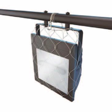
12 Installation of Wire Clamps Safety Nets and Meshes Wire clamps are used to form wire rope attachments and terminations. Incorrect installation of wire clamps on lifting equipment will likely result in failure. These safety securing devices fully enclose equipment fixed at height that presents a high risk of becoming a dropped object. Clamps of a type with two gripping surfaces are recommended Wire clamps should be sized to the dimension of the wire Designed to be easily installed, they are particularly well suited to applications where equipment or its components are assessed to be at risk of failure due to factors such as numerous components, design quality, internal or external corrosion, vibration and so on. Clamps should be designed to prevent incorrect assembly It is a requirement that wire clamps are assembled in accordance with the manufacturer s guidance and relevant industry standards Number of clamps to be installed depends on diameter of the wire and should comply with manufacturer's specification Clamp bolt torque should be applied in accordance with the manufacturer s guidance. Always refer to net or mesh manufacturer s recommendations for appropriate selection, installation, maintenance and product life limitations Ensure product is suitable for the operation and the environment, with due regard to potential galvanic corrosion Detailed risk assessment should consider catastrophic failure of primary fixings both with and without safety nets, meshes or safety wires The operational integrity of any electrical equipment should not be compromised or impeded by the introduction of safety nets or meshes As with all other safety securing devices, safety nets and meshes should be regularly inspected and replaced if they no longer perform their intended function Carefully assess any impact on other activities such as general maintenance access or snagging hazards. Iron grip wire clamp In accordance with industry standards and regional directives, Bull-dog, U-bolt or hoop style clamps should not be used as wire clamps in connection with lifting operations.. 20 Securing Methods Revision 4 DROPS Reliable Securing Revision 4 21
 Human Factors (operator error, poor behaviour, complacency, neglect) Inadequate Procedures (bad planning, no management of change) Failed")
13 TOP CAUSES OF DROPPED OBJECTS Understanding Dropped Objects Safety alerts and incident reports show these recurring themes continue to result in dropped objects: Inadequate Risk Assessment (failure to identify dropped object hazards) Human Factors (operator error, poor behaviour, complacency, neglect) Inadequate Procedures (bad planning, no management of change) Failed Fixtures and Fittings (corrosion, vibration, poor design, selection or improper installation) Poor Housekeeping (pre-existing hazards from previous tasks) Collisions and Snagging (lifting, travelling equipment, tag lines, service loops) Inadequate Inspection, Repair and Maintenance (ignoring unsafe conditions) Redundant, Neglected and Home-made Tools and Equipment (should be eliminated) Inadequately Stored or Secured Tools and Equipment (no lanyards or tethers being used) Environmental Factors (wind, sea motion, ice, snow, extreme conditions) Dropped Objects also account for significant equipment and environmental damage. Even items that fall into the sea can still carry enough force to cause severe damage to critical subsea infrastructure. Dropped objects are bad for business too, even when nobody gets hurt. Dropped Objects continue to pose the number one risk of serious injuries, fatalities and equipment damage in several industries worldwide. Similar statistics apply to leisure activities and home life too. Concerted campaigns and directives have resulted in better dropped object prevention awareness, but the overall trend shows no sign of significant improvement. What is a Dropped Object? Any item that falls or falls over from its previous position that has the potential to cause injury, death or equipment / environmental damage. Dropped objects may be further classified as static or dynamic. Static Dropped Object Any object that falls from its previous position under its own weight due to gravitational forces (ie without any applied force). For example failure caused by corrosion or improper fixings. Dynamic Dropped Object Any object that falls from its previous position due to applied force. For example impacts involving travelling equipment or loads, snagging on machinery or stacked items, motion, helicopter downdraft or severe weather. What Causes Dropped Objects? A host of factors can contribute to a dropped object incident. It is important to consider these during worksite hazard identification. Energy sources such as gravity, wind, heave and mechanical motion can all contrive to initiate a sequence of events that result in something falling. Add corrosion, lack of awareness and inadequate inspection or maintenance and you can almost guarantee a dropped object will occur. Statistics show that around 30% of all dropped object incidents are related to design, technical or mechanical issues but almost half can be attributed to human factors. (Source DORIS) What Should We Do About It? We cannot simply accept that dropped objects are an inherent hazard of our working environment. A system should be put in place to identify and prevent, and where reasonably practicable, manage the risks associated with dropped objects. This handbook is designed to help you do just that Understanding Dropped Dropped Objects Objects Revision 4 DROPS Reliable Securing Revision 4 23

14 DROPS Calculator The DROPS Calculator (shown opposite) provides a common benchmark in the classification of the potential consequences of a dropped object. One of a number of similar tools, the DROPS Calculator is endorsed by the DROPS Workgroup and recognised by the majority of Operators and Contractors in the global oil and gas sector. While other calculators exist, they all follow the same principle plotting the mass of a dropped object against the distance it falls to determine its possible consequences. CONSIDERATIONS: The calculator assumes a blunt object so is not compatible with broken glass, metal shards etc which may puncture the skin and damage tissue/organic functions The wearing of standard PPE, eg hard hat, safety boots and eye protection, is assumed in the calculator There is no requirement to subtract the average height of an individual when determining fall distance. The calculation is based on the object striking solid ground. Remember personnel may be crouched or prone, or objects may strike lower parts of the body DROPS Calculator and other similar tools are guides only providing cursory indication of possible outcome they are not an accurate prediction In reality, even a small object falling from height can be lethal. The heavier the object, the more severe the consequences - the further it falls, the more severe the consequences. The DROPS Calculator is best employed during planning and risk assessment processes. It will determine the potential severity rating of potential dropped object hazards and help with the risk ranking of appropriate corrective actions and control measures. Metric, Imperial and Electronic versions of the DROPS Calculator tool are available at 24 Understanding Dropped Objects Revision 4 DROPS Reliable Securing Revision 4 25

15 Responsibilities POLICY AND PROCEDURE Corporate guidelines and standards should ensure that appropriate inspection and control mechanisms are implemented to identify, assess, eliminate or manage potential dropped object risks. Preventive controls and mitigating measures should be detailed in specific procedures to address the inherent dropped object hazards associated with task. It is important that we identify and accept our Roles and Responsibilities as set out in these documents. However, everyone has a responsibility to prevent dropped objects through: Observation and Intervention (being aware of the hazard, associated risks and prepared to stop work if conditions or actions are unsafe) Elimination (the removal of potential dropped object hazards if it is safe to do so, ensuring all loose items are cleared from the worksite before and after each task) Control (ensuring all items of structure, equipment and tools are securely fastened or tied off, especially when using tools and equipment at height) Reporting (recording all potential and actual incidents in accordance with company policy) Design and Procurement (informed selection, engineering and availability of tools, equipment, materials and resources) Inspection (regular and periodic worksite inspections of all high risk items, particularly loads prior to lifting or transportation). DISCOURAGED PRACTICES: DROPS strongly discourage the following methods, techniques and actions: Uncertified lifting equipment including home-made lifting devices Home-made or customised tools and equipment Use of welding rods / wire / tie wraps instead of split pins or safety securing pins Use of two part shackles for lifting or permanently suspended equipment Loaded / tensioned bolts secured with a double nut arrangement Unsecured hand tools at height, DESIGN AND PROCUREMENT BEST PRACTICE: Company Policy and Procedures governing dropped object prevention should be understood and communicated to suppliers and partners Opportunities to incorporate DROPS Reliable Securing Best Practice at each critical design and selection stage should be identified All materials and equipment despatched for use in the field should be securely packaged for transportation All materials and components should be suitably rated for the operational environment. Where stainless steel is selected, there should be due consideration of the potential for galvanic corrosion including grease tubes / guns, water bottles, radios, detectors, pens, phones, etc Wire slings tied or wrapped around beams Loads left suspended without proper authority Use of scaffolding equipment for permanent structures or mountings, including uncertified use of scaffold for lifting equipment Leaving fall arrestors un-retracted when not in use. It is widely acknowledged that there are many challenges in selecting and sourcing products and services in each global sector. DROPS recommend the following considerations are taken into account: All items selected for installation or use at height should incorporate appropriate barriers and be readily traced and certified if necessary All items secured at height should be situated to reduce or eliminate the risk of damage by snagging or collision All Safety Securing devices should include batch marking, manufacturer details and clearly tagged details of maximum load or working load limit Suppliers and Partners should be encouraged to support the initiative through active involvement and innovative improvements. 26 Understanding Dropped Objects Revision 4 DROPS Reliable Securing Revision 4 27

16 Task Planning and Risk Assessment Effective task planning and risk assessment will ensure appropriate resources and personnel are assigned for the task to eliminate or reduce the likelihood of a dropped object. When the potential for a dropped object has been identified, the primary focus should be to implement preventive controls to eliminate or minimize the likelihood of the dropped object occurring. However, robust mitigating controls should also be implemented to reduce the consequence of a dropped object should the preventive controls fail. Tools, equipment, structures, lights, suspended loads, temporary or portable appliances and any pre-existing loose items will always be a threat. Effective task planning and risk assessment will reduce the consequences and eliminate exposure to personnel. Consideration should be given to the potential path that a dropped object may take during the Task Planning and Risk Assessment phase. Considerations should include but not be limited to the potential deflection points, environmental factors, dynamic factors and the potential dropped object s shape as they will affect the shape of the cone. If the object falls overboard, consider if there are subsea assets or critical infrastructure that may be affected. Additional information relating to Subsea dropped objects can be found on the DROPS website. Task Planning and Risk Assessment should include but not be limited to: Pre and Post Inspections of Worksite (remember loose items may have been there for years) Load Inspections prior to transportation or lifting (certification, equipment, loose items) Working conditions, equipment and operative's competence (consider behavioural influences too) Understanding each phase of the task, piece of equipment being employed and the associated hazards and challenges (Operators actions are likely to create scenarios where dropped objects can occur) Realistic risk-based identification of dropped object hazards to ensure correct application of controls and resources (as opposed to identification of dropped object hazards in general) Potential path of travel should the identified item drop (cone of exposure) Effective control of service partner and/or temporary equipment (be ready to help, not everyone will be familiar with every element of dropped object prevention best practice). Wherever possible, eliminate unnecessary dropped object hazards at source. For those items that remain, carefully assess the likelihood of static or dynamic failure (based on common causes, experience and site-specific alerts) and determine the potential severity should it fall (using the DROPS Calculator). Remember that controls may already be in place (such as procedures, checklists, safety wires etc), so be prepared to identify these and ensure they are adequate. Where new physical controls are recommended, always consider the potential for new dropped object hazards. Mats, covers and nets can fall too. Additional controls will be subject to Management of Change processes. Cone of Exposure ENVIRONMENTAL FACTORS: Gravity is an inherent hazard in every workplace. When combined with constant exposure, sea motion and severe weather conditions, the risk of dropped objects increases significantly. During all tasks, particularly transport, lifting and working at height, take special care to identify and mitigate dropped object incidents that can be caused by environmental factors. Temperature (cold hands, sweaty hands, materials perishing) Winds and Helicopter Downdrafts (box lids, doors, signage, meteorological equipment, stacked items) Sea Motion (stacked items, shelving, loose items, suspended items) Load Movement (forces exerted on loads during transportation and lifting, eg. road conditions, turning, braking etc) Ice and Snow (icicles, ice build-up, hard packed snow can also obscure loose items) Rain (accumulations in buckets and vessels can add significant weight) Mud and Sand (can add weight but also obscures loose items, particularly on cargo units) Fog, poor light, sun light, darkness can also become contributing factors when vision is critical to safe operations. 28 Risk Management Revision 4 DROPS Reliable Securing Revision 4 29


17 Preventive and Mitigating Barriers (Controls) Barriers are functions and measures designed to break a specified undesirable chain of events. In other words, their function is to prevent a hazard, such as a dropped object, from manifesting itself or to mitigate the consequences by breaking an undesirable chain of events. We describe some of these in a little more detail, and where applicable make reference to other sections within this handbook. INDEPENDENT SURVEYS AND INSPECTIONS Independent Surveys are typically carried out annually and are expected to identify all potential dropped object hazards and, where possible, assist with the removal of any unnecessary or redundant equipment. The Independent Survey Specialist will provide a Survey Report, presented by areas and zones. Failed Items are reported to the asset management team. An Inspection Book, based on the Survey is then presented to the asset team for their daily, weekly and periodic inspections. Inspection programmes should cover the entire Facility / Installation and inspection periods should be determined based on likelihood and potential consequence of dropped objects. Inspection Books are regularly updated to reflect any changes in equipment and conditions. Third Party and temporary equipment should also be incorporated within the system. These are our barriers to prevent dropped objects. We need them all to be synchronised for our barriers to function. In managing dropped object risk, we first identify and ensure that our preventive barriers are in place. These will reduce the likelihood that an incident will occur. Where we consider the risk that these preventive barriers will fail, we put mitigating barriers in place to reduce the likelihood that an incident will reach its full potential. Typical Survey Report and Picture Book Dropped Object Survey and Inspections are provided in many different formats, including integrated electronic systems. Further information on DROPS Surveys can be found at under the heading Guidance Documents and Best Practices. 30 Risk Management Revision 4 DROPS Reliable Securing Revision 4 31

 Recognising personal responsibilities (compliance, intervention and improvement).")
18 DROPPED OBJECT AWARENESS All personnel should demonstrate a basic understanding of dropped object hazards and the need to comply with all dropped object prevention policies and processes. Training, familiarisation and on-the-job coaching is key to achieving this. These are the key objectives of a dropped object awareness programme: Identifying and assessing potential hazards, their causes and consequences (observation and reporting) Understanding the methods for control and prevention (task risk assessment) Recognising personal responsibilities (compliance, intervention and improvement). Further training in use of Tools at Height systems, Working at Height, selection and application of safety securing devices etc should be made available as appropriate. TIME OUT FOR SAFETY Everyone has the authority to stop work - but we don t have to wait for an unsafe act or condition to arise before we do. Take Time Out to discuss potential dropped objects at the worksite. Share experiences and learn from recent alerts and incidents use this knowledge during task risk assessments. Discuss changes in the environment and how they might affect equipment and structures around you. Plan your Time Out sessions around your task, providing opportunities to review hazards and check that controls are still in place. SAFETY MEETINGS AND AUDITS DROPS encourages regular dropped object management meetings to be held at worksites to discuss observations, incidents, survey and inspection reports, recent industry alerts and any improvements that could be made in dropped object prevention performance. Focal Points and Subject Matter Experts can be assigned to engage with personnel, ensuring preventive measures are functioning and that Third Party or temporary equipment has been considered and included. Worksite Dropped Object Prevention Committees or Working Groups may be established to regularly discuss performance, incident reports, lessons learned, best practice and new techniques or tools available on the market. DROPS recommend that all service partners are included in such groups. PRIMARY SECURING Ensure the correct Primary Securing Method is used when installing equipment, eg nuts, bolts, screws, clamps, brackets, turnbuckles or welding. The Original Equipment Manufacturer s (OEM) recommendations for securing should always be identified and observed. Where possible, the securing method for objects identified as having the potential to drop at the Task Planning stage should be known to the persons involved in the task and they should assure themselves that the object is secure prior to work commencing. SECONDARY RETENTION AND SAFETY SECURING SYSTEMS Wherever possible, equipment installed at height or in an area where potential exists for the object to drop to a lower level, should have integrated secondary retention. Where this is not possible, or where such equipment is exposed to a risk of collision the equipment should have additional safety securing in the form of wires or chains and connectors that are securely attached to the main structure. Best Practice Recommendations are detailed in this handbook. PREVENTIVE MAINTENANCE (also Planned or Condition Based Maintenance) The primary goal of Preventive Maintenance is to preserve and restore equipment reliability by replacing worn components before they actually fail. Preventive maintenance activities include partial or complete overhauls at specified periods. In addition, equipment deterioration can be recorded so that worn parts can be repaired or replaced before they cause system failure. The ideal preventive maintenance programme would prevent all equipment failure before it occurs. COLLISION CHECKLISTS A Collision Checklist should be developed and available at each Equipment Control Station. Before starting a task where equipment will be moved, the equipment operator should review the appropriate Collision Checklist for obstructions that may result in a dynamic dropped object. For example, a Crane Operator s Collision Checklist would include any equipment that the boom could collide with during a lifting operation. 32 Risk Management Revision 4 DROPS Reliable Securing Revision 4 33

19 ZONE MANAGEMENT Facilities have some areas that have a higher risk of potential Dropped Objects than others. A comprehensive review and risk assessment is conducted for different areas of the facility to determine the potential for Dropped Objects and measures are implemented to restrict or prevent access to areas where hazards are present. The following zones are defined in DROPS Recommended Practice: Restricted Access Zone : An area in which a Dropped Object potential has been recognized. The area is identified within the operational permit-to-work and authorized entrants are limited to the personnel needed to perform the work. Physical barricades and signage clearly identify the covered area and the specific risk of the zone. No-Entry Zone : An area in which a Dropped Object potential has been recognized (eg, where moving equipment is present, where personnel are working at heights) and personnel are not permitted while the hazard is present or active. These zones are identified in the permit-to-work, controlled to prevent unauthorised access, and differentiated from the Restricted Access Zones by barricades and signage. Identifying and implementing No-Entry and Restricted Access Zones is effective for reducing the potential of personnel exposure to Dropped Objects. Restricted Access and No-Entry Zones apply to all personnel at the location (eg, service partners and providers who perform work or visit the location). Zones can be further classified as follows: Permanent Zone : An area where a permanent barrier has been established to raise awareness of potential Dropped Object hazards and prevents personnel from entering whenever equipment is being moved or operated (ie, Red Zone, DROPS Zone). An area only entered by personnel authorized and permitted to conduct work during that time. Temporary Zone : An area where a temporary barrier has been established to raise awareness of potential Dropped Objects hazards and to prevent personnel from unauthorised entry (eg, using of barrier tapes, barrier chains, signage, etc). ZONE MANAGEMENT (continued) Zone classification and management are based on the usual, routine operations and activities in the area. A change in operations in the area can alter the risk zones and may require a temporary change in zone classification, depending on the risk assessment. Zones and their access points are clearly marked, and responsibilities should be clearly established, delegated, and communicated to ensure effective implementation. Site diagrams are posted in common areas and at the location of the managed zone(s) to ensure personnel are aware of the access protocol and how to navigate through and around it. Signs are in English and any other predominant language(s) at the location. SECURING OF TOOLS AND EQUIPMENT See Best Practice Recommendations in this handbook (Pages 46-53) HOUSEKEEPING Items that are not in use or not in service are often excluded from established inspection and maintenance procedures and present considerable risk potential. Tools and equipment, redundant machinery, scaffolding components and other loose materials left from previous works regularly feature in dropped object reports. Before work starts and when the work is complete, a full check should be carried out to ensure that no loose material or equipment has been left, especially at height. PERSONAL PROTECTIVE EQUIPMENT Standard workplace PPE offers limited protection against falling objects. Ensure that all equipment is appropriate for the task and certified for use. Anyone using personal protective equipment against falls from heights should have documented training. 34 Risk Management Revision 4 DROPS Reliable Securing Revision 4 35

20 General Tips for Dropped Object Free Worksites Securing Equipment During Severe Weather Before starting any task, consider the potential for dropped objects. Even if your task is not at height, consider the environment where you will perform the task and any other activities that may be going on around you. Pay particular attention to environmental factors such as wind, sea motion, light, downdrafts, road conditions etc. Before commencing the task, visually inspect the work area for pre-existing dropped object hazards such as loose items and debris. Check all equipment and structures in the area to ensure that all fastenings, bolting, covers, panels, hatches, removable guardrails etc are properly secured. Check all safety securing features are in place (split pins, locking wire, locking washers). Look out for moving machinery and corroded brackets and structure. Identify existing controls are in place such as toe-boards, guards, barriers, communications etc. Also consider the following: Inspect all Tools and Equipment (certification, damage, securing points, lanyards, tool bags) Identify Dynamic Potential (collision, snagging, movement, load-shift) Identify Dropped Object Scenarios (discuss during tool box talks, take regular time-outs to re-evaluate) Structures and equipment should be designed so that water cannot collect and form ice Establish routines for inspection before, during and after adverse weather conditions, such as strong winds, high waves, and the risk of ice / falling ice Use available time during shift changes to carry out an extra check of equipment that may loosen Check whether the workplace is clean and tidy. Equipment stored on deck and in other areas may be blown over by the wind or downdrafts, so check the securing devices Check windsocks, wind sensors, floodlights, antennas, antenna masts and scaffolding Carefully check that equipment in the vicinity of the helideck is sufficiently secured Check for any loose objects on roofs, load carriers and in all storage areas Check that the lids of storage boxes are secured. Pay particular attention to lighting and other fixtures that may not be secure or present a snagging / collision hazard. Remove loose items from pockets (tools, radios, detectors, water bottles) and secure them properly. Identify and assess energy sources that can cause dropped objects. Gravity, Motion, Mechanical Movement, Electrical or Pressurised equipment, Vibration even Temperature can cause dropped objects. (Cold hands can lead to loss of grip on tools, expansion and contraction can damage fixings etc.) 36 General Tips for DROPS Free Worksites Revision 4 DROPS Reliable Securing Revision 4 37

21 Observation Techniques Unnecessary Equipment at Height Identification, assessment and risk ranking of findings will address opportunities to eliminate or manage potential dropped objects. Regular Hazard Hunts can be implemented, raising awareness whilst making the worksite a safer place. DROPS recommend that all tools AND equipment are carefully assessed for suitability for use at height. Many cases have been reported where redundant or unnecessary equipment has been left at height presenting significant hazards to personnel and plant below. Set aside time and limit the area to be inspected Concentrate on categories of potential items (eg loose material, panels, lighting, corroded structure etc) and establish how these are secured and if they require removal or repair Findings that do not conform to Best Practice and cannot be immediately rectified safely should be reported to the Area Authority. To assist in risk ranking, include description of item and area, potential consequence if it were to fall (DROPS Calculator), possible causes (corrosion, collision etc) and if appropriate suggested recommendations for remedial action Follow up on all items reported. Corrective action is after all a decisive factor in preventing dropped objects. IMPORTANT CONSIDERATIONS: Involve everyone in this process, a fresh pair of eyes can be beneficial Ensure all hunters have secured all personal equipment and that bags or containers are available for appropriate collection and disposal of debris Advise the importance of accurately reporting location of any items that may appear to be integral components of equipment or its fixings (eg bearings, bolts, brackets). This may be an early warning sign of a potential failure. Always anticipate unidentified legacy hazards (eg shipyard tools, construction debris, scaffold clamps etc) Record all construction, maintenance and repair materials taken aloft. Ensure all material removed or not required is taken down safely Regularly carry out a risk assessment and review of what equipment is required at height, and what should be removed The review should establish whether equipment should be relocated to reduce the risk of collision with mobile equipment Inspection and maintenance procedures should be revised regularly, to ensure inspection and maintenance of all equipment installed at height Always carry out a final check to ensure that no tools, equipment or materials are left behind at height. 38 General Tips for DROPS Free Worksites Revision 4 DROPS Reliable Securing Revision 4 39
22 Post Inspection / Final Check of the Worksite Workplace Best Practice Experience shows that a clean and tidy workplace is less exposed to dropped object risk than an untidy or poorly managed work area. On facilities and installations with rotations and shift work, this effect is intensified by the fact that we are also exposed to other people s clutter. It is therefore extremely important that we have good routines for final checks of the worksite. Work operations often involve work at height. Many operations therefore contain an element of risk as: You are exposed to work or equipment above you Personnel below you are exposed to your work You are working at height and could fall Always keep your worksite tidy, even small items can create unnecessary hazards Tools, equipment and materials should be secured in a safe location at the end of each shift When the work is finished, a final check and inventory count should be carried out to ensure that no tools, equipment or materials are left behind at height Check that all equipment is installed, secured and returned to normal operation (eg replace locking wire, close and secure latches) The worksite should be left in a clean and tidy state, and all tools, equipment and materials should be returned to their designated storage places Loose objects at height should be removed, attached or secured On mobile units, a risk assessment should be carried out to determine whether equipment on work benches, shelving and racking should also be secured. In the remaining part of this booklet, we distinguish between the securing of personnel working at height, the securing of permanent equipment, and the securing of tools and parts that are used at height during a work operation. Ideally, all work should be carried out on the ground or at a level where all edges and openings can be secured to prevent persons or objects falling to a lower level. Where there is a requirement to work at height, you should refer to your Employer s Work at Height Policy and Procedures. These procedures will ensure compliance with relevant legislation on securing of personnel, erection of working platforms, over-the-side work, ladders, hoists, tools and other devices. Other key considerations such as access control, safety equipment and rescue plans will also be covered. However, dropped objects caused by failure to secure tools and equipment continue to happen whilst they are being carried to the worksite, used or stored at height. This includes radios, detectors, pens, gauges, hard hats, water bottles and many other personal items that really should be secured properly or not taken aloft in the first place. Remember, if the task cannot be undertaken at ground level and you should work at height, refer immediately to your Employers Work at Height Policy or ask your supervisor for assistance. 40 General Tips for DROPS Free Worksites Revision 4 DROPS Reliable DROPS Securing Reliable Revision Securing4 41

23 Securing of Personnel Common Causes of Incidents: Complacency, Incompetence, Lack of Supervision, Uncertified or Damaged Fall Arrest Equipment, Operator Error, Poor Communication, Snagging and Collisions, Environmental Factors. The choice of equipment to be used should be made after evaluating the work place environment Established control procedures should be followed before, during and after use Anyone using personal protective equipment against falls from height should have documented training (including rescue method training) Nobody should work alone or unattended when using fall arrest equipment Everyone involved in the work scope should have sufficient training and awareness of the equipment and safety procedures A Buddy check of all fall arrest, rigging and other equipment should be carried out The necessary rescue equipment and trained personnel should always be available at the workplace Fall arrest equipment should comply with relevant national / international standards, incorporate an anti-trauma safety device and comply with an accepted standard The equipment should be checked EVERY TIME before use and should be checked at least every 6 months by a competent person The date for next inspection should be clearly shown on the equipment The anchor point for suspension should be identified and rated to comply with relevant national / international standards, eg. OSHA. 42 Working at Height Revision 4 DROPS Reliable DROPS Securing Reliable Securing Revision 44343

24 Derrick Evacuation Equipment Far too many defects have come to light in evacuation equipment. In many cases there is deficient certification, control and labelling of harnesses and blocks (brakes). Riding belts and blocks should be certified, controlled / inspected and labelled in line with other anti-fall equipment The guide line, its attachment points and connectors are also defined as anti-fall equipment and should be certified, controlled / inspected and labelled accordingly It should be possible to use the equipment for the safe performance of entry and evacuation operations The equipment should be checked every 6 months by a competent person and should be marked with the next inspection date. Riding belts should be connected to guide lines and blocks and stored so as to protect them from wear and tear / damage from external factors Ensure evacuation equipment boxes are secured and that lids and catches are in good condition. Remove unnecessary items that may have been left in boxes. 44 Working at Height Revision 4 DROPS Reliable Securing Revision 4 45
 All tools should be suitable for use at")

25 Securing Tools <5kg / 11lbs Proprietary tools and tool kits, designed specifically for use at height are widely available. All use of tools at height should be risk assessed for suitability and for application (working environment, access, tool condition, competence of user etc) All tools should be suitable for use at height and secured against being dropped whilst they are being carried to the worksite, used or stored at height (use tool bag with internal loops when several and / or heavy tools are required) If an anchor point other than the belt or bag is required, use an appropriate part of the surrounding structure, preferably above the work level Tools heavier than 2kg / 4.5lbs should not be secured to the body, secure them to the adjacent worksite structure For work on or near rotating machines or travelling equipment, all tools should always be secured to the adjacent structure Attachment points / devices on tools and bags should be documentable (not all apertures on handles are actually rated tie-off points) All connectors/snap hooks/ carabiners should be made of acid proof steel (AISI 316), include screw lock or self-lock gates and include captive eyes (see also Page 18) Lanyards on tools attached to the body should ideally be energyabsorbing (fall damper) The standard use of wrist lanyards is discouraged, however, it is recognised that they may be appropriate to specific tasks, eg within confined spaces Velcro wrist lanyards are discouraged where the integrity of the fastening may be affected by the work environment Tools used at height should be checked out / in (see Page 54) in a Register to ensure that nothing is left behind. Proprietary tools for use at height and their retention components should not be modified. Using non-proprietary or modified tools, or alternative retention accessories may compromise integrity. Lanyard attachment points (moveable, spring clip or fixed) should be selected according to size and weight of tool. 46 Working at Height Revision 4 DROPS Reliable DROPS Securing Reliable Revision Securing4 47

26 Securing Tools >5kg / 11lbs Proprietary tools and hand held machinery for heavy duty use, specifically designed and manufactured for use at height are widely available. All use of heavy tools and hand-held machinery where equipment may fall to an underlying level should be risk assessed All heavy tools and hand-held machinery used at height should be secured against being dropped, both when in use and while being transported Securing points for tools and machinery should be in place above the work site, attached to the surrounding structure, not to scaffolding or pipework Tools heavier than 2kg should not be secured to the body, secure them to the adjacent worksite structure One piece sledge hammers (forged construction with secured head) should be used at height The attachment points / devices on tools should be documented and all securing wires inspected in accordance with the manufacturers recommendations The securing wire should be as short as possible to reduce shock loading effect Energy absorbing lanyards and tethers can stretch beyond the safe calculations or drop distance, therefore fixed securing wires should be used on heavy tools at height, according to the work environment Only certified lifting equipment should be used as securing devices (where appropriate) Tools used at height should be checked out / in (see Page 54) to ensure that nothing is left behind. Proprietary tools for use at height and their retention components should not be modified. Using non-proprietary or modified tools, or alternative retention accessories may compromise integrity. 48 Working at Height Revision 4 DROPS Reliable DROPS Securing Reliable Revision Securing4 49

27 Tool Cabinets for Work at Height Tool cabinets for work at height are now readily available and employed on many facilities. The appropriate recording, securing and control of tools used at height can help to eliminate unnecessary dropped objects at the worksite. All tools should be appropriate for use at height and they should have documented attachment points All tools should be adequately secured within the cabinets In addition to the necessary tools, cabinets should be equipped with: - a sufficient number of correctly dimensioned safety wires / lanyards - a sufficient number of connectors / snap hooks / carabiner hooks with screw lock and eyelet - special belts for fastening tools and bag - a sufficient number of tool bags with internal fastening devices Each cabinet should have an inventory list of certified and traceable contents and be kept locked, and one person should be designated as responsible for the cabinet The responsible person should register all tools taken from and returned to the cabinet, with the authority of the Area Lead. The contents of the cabinet and the register of tools in use should be checked at the end of every shift. Date TYPICAL TOOLS ALOFT REGISTER CHECK TOOLS OUT VERIFY TOOLS RETURNED Description of Tools / Equip. Name Authorised (Area Lead) Time Date Description of Tools / Equip. Name Authorised (Area Lead) Time 50 Working at Height Revision 4 DROPS Reliable DROPS Securing Reliable Revision Securing4 51

28 Securing Other Portable Equipment There have been several incidents reported where portable equipment such as radios, gas detectors and digital cameras have been dropped from height. All portable equipment used where there is a risk of the equipment falling to an underlying level should be secured against being dropped Carrying pouches should always be used for radios and any other portable equipment without certified securing points Locks on pouches should have a double securing mechanism to prevent unintentional opening Belt clips that allow equipment to become detached when turned 180º should not be used Belts with snap fasteners are not suitable for securing equipment at height Battery compartments and covers on portable equipment should be secured to prevent internal components from falling. Remember even small items falling from significant heights can cause injury and damage. Ensure all personal equipment (tally books, pens, callipers, cameras, water bottles etc) is secure in a fastened pocket or carry pouch. If the item is not required for the task, do not carry it at height - leave it at ground level. 52 Working at Height Revision 4 DROPS Reliable DROPS Securing Reliable Revision Securing4 53
 particularly following repair and maintenance tasks.")


29 Securing Equipment and Parts Other than tools, there have been a significant number of dropped objects due to loose or discarded items left at height (eg. nuts, bolts, screws, pins, used or replaced parts and components etc.) particularly following repair and maintenance tasks. Consider every item carried aloft as a potential dropped object and ensure that all material is removed from the worksite on completion. All repairs and maintenance work carried out at height should be risk assessed Create an inventory of all items being taken aloft Ensure all equipment, parts and materials being used at height are secured against being dropped Gratings and gaps in toe boards should be covered with suitable mats or netting When the work is finished, a final check and inventory count should be carried out to ensure that no tools, equipment or materials are left behind at height. Smaller parts should be stored in suitable storage boxes, bags, etc Transportable worksite safety mat and accessories 54 Working at Height Revision 4 DROPS Reliable DROPS Securing Reliable Revision Securing4 55


30 Mobile Elevated Work Platforms Loose tools, equipment and other items present a risk of dropped objects when working on mobile elevated work platforms (MEWPs). Ensure that the platform does not get congested and consider installing a suitable method of enclosing the unit when working at height. Ensure the working platform is clear of unnecessary items and that all controls are not impeded by equipment or tools All equipment should ideally be kept below the height of the toe board, and secured to the platform during rise, at operational height and during descent Smaller tools and parts should be stored securely in suitable containers or tool bags Equipment should not extend beyond the guard rails during rise and descent Protective screens should be installed around the platform rails, suitably designed for the operation and the environment Protective screens should be inspected both prior to use and on completion of the task for any openings, gaps or damage that may affect the integrity of the screen Conduct an inventory count of all materials to ensure no tools, equipment or other items are left behind at height. 56 Working at Height Revision 4 DROPS Reliable DROPS Securing Reliable Revision Securing 4 57

31 Hoisting, Lifting and Suspended Items Industry employs a wide range of fixed and temporary hoisting and lifting devices, all of which should comply with standard industry legislation and best practice. DROPS recommends it is best practice to give all suspended items the same considerations as for hoisting and lifting equipment, ensuring appropriate certification, inspection and maintenance management is applied. The following equipment (appliances and accessories) should be considered as suspended items and should be recorded in the lifting equipment register and inspected regularly: Counter weights and other suspended compensating devices Bunkering hoses, tow bridles and other over the side equipment Halyards and other flag hoisting devices Temporary suspension for wireline, coiled tubing, snubbing or stimulation equipment Beam clamps, chain hoists, crane hooks, rigging hooks Synthetic strops, webbing slings and steel slings. A complete register of all lifting equipment used to hoist, lift or suspend such items should be available to record data on all lifting equipment and its certification status, including ID number, WLL and date into service. The register should include items such as slings, shackles, pad eyes, trolley beams, hoists, lifting caps, lifting attachments or devices. It is important to incorporate all these items within any dropped object survey and inspection management system. Inspection criteria is likely to include: Check arrangement of suspension equipment is in accordance with lifting and hoisting best practice Check certification and test certificates Check general condition of components (fatigue, corrosion, impact or other form of damage) Check application of equipment (correct sizing and fitting) Check all shackles are complete with safety securing (split pin / cotter pin) Check appropriate authority has been granted for all loads left suspended. All personnel lifting equipment and activities should comply with relevant national regulations, OEM recommendations and industry and corporate best practices. All other equipment such as forklifts, elevators, powered aerial work platforms, baskets etc should be maintained and operated in accordance with relevant legislation, OEM recommendations and industry and corporate best practices. Where employed, temporary access such as scaffolding, work platforms and staging should be designed and checked to confirm adequacy of design and construction, and fitness for planned personnel and equipment loads. HOME-MADE LIFTING DEVICE Uncertified equipment (inc shackle) Sling doubled back Incorrect application of clamps Potential for snagging Bunkering Hose Suspension - Not Best Practice Handrails, safety gates / barriers and toe boards should be incorporated into the working platform where a risk assessment has shown that there is a danger of personnel or materials falling from that platform. Where indicated by the risk assessment that fall protection should be used by persons working on such platforms, secure mountings for the fall protection equipment should be in place and identifiable. POOR CLAMP SELECTION Incorrect sizing Possible fatigue/corrosion 58 Hoisting, Lifting and Suspended Items Revision 4 DROPS Reliable DROPS Securing Reliable Revision Securing4 59
 should replace safe working load (SWL) in describing the capacity of items such as hooks, slings, shackles")

32 Correct Use of Shackles Shackles are used in lifting and static suspended systems as removable links to connect wire rope, chain and other fittings. In recent years, both US and European Authorities have agreed that working load limit (WLL) should replace safe working load (SWL) in describing the capacity of items such as hooks, slings, shackles etc. The WLL is always specified by the manufacturer. In Line WLL = 100% A general definition of WLL is: the maximum mass or force which a product is authorized to support in general service when the pull is applied in-line, unless noted otherwise, with respect to the centre line of the product. 45o WLL = 70% 90o WLL = 50% WLL Reduction Factors Where side loads cannot be avoided, reduction factors should be taken into account. Always refer and adhere to manufacturer's guidance or technical data sheets. Shackles should be individually identifiable and have an adequate WLL and an in-date, certified and approved inspection record. Where colour coding post inspection is used, this should be in place 4-Part Shackles (Safety Bolt type) should be equipped with two barriers: nut and stainless steel split pin / cotter pin Split pins / cotter pins should be of the correct size and sufficiently splayed to prevent them from being knocked out or causing injury Linch pins, nappy pins or R-Clips should not be used during lifting as these may be knocked out or cause snagging (also see Page 17) 2-Part Shackles (Screw Pin or Round Pin type) should never be used for permanent suspension or in any application where the pin can roll under load and unscrew Shackles should only be used for their intended purpose and manner The user should be familiar with the applicable limitations and guidelines for use (always refer to manufacturer's data sheet) Shackles are designed to support the load at the bottom of the hollow torus and evenly across the shackle bolt If shackles are exposed to loads in other places, this should be taken into account during use as it will reduce capacity Where point loading is unavoidable, ensure load is centred, where necessary, use packing to centralise the load on the shackle bolt Never load shackle pin to shackle pin and refer to manufacturer s guidance for further details Side loading of shackles in not permitted for some shackles and should always be avoided. (Side loading reduces the WLL factor (see figure opposite). Where a degree of side loading is unavoidable, manufacturers' guidance should always be adhered to Where flat slings are in use, sling shackles should be considered to maintain 100% of sling WLL and provide a more even load distribution within the sling fibres. Not all shackles may be side-loaded, eg sling shackles. Always refer to manufacturer's technical data sheets for loading and operational limitations. Shackles come in a variety of forms and the correct type should be used for the respective work / application. Split pins / cotter pins should be of the correct length. Ensure pins are properly splayed (as shown here) to reduce the risk of snagging and injury. 60 Hoisting, Lifting and Suspended Items Revision 4 DROPS Reliable Securing Revision 4 61

33 Sheaves and Snatch Blocks The DROPS Reliable Securing Focus Group has, through co-operation within the industry and equipment manufacturers considered best practice methodologies for installation and use of permanent and temporary blocks at height. This collaboration and study has focused principally on the secondary retention of sheave and snatch block fastenings, and the importance of informed risk assessment to identify requirements for the addition of safety securing wires or slings. Blocks should have two integrated barriers in both the head fitting and the shaft ie primary fixing (forged, machined, threaded) and secondary retention (split pin, lock wire) Side plates should contain / enclose / capture the sheave should a centre pin failure occur, and catch the line in the event that it jumps the sheave Only 4-Part shackles (bow, pin, nut and split pin) should be used for the suspension of sheave blocks All blocks and suspension shackles should be marked with ID number and load rating All detachable caps, guards and covers should incorporate secondary retention, or safety securing where no secondary retention is possible A documented maintenance programme should be established. It is a requirement that blocks, shackles and lifting lugs should be inspected at least every twelve months by a competent person Blocks should be dismantled at the request of the competent person or in accordance with the manufacturer s recommendations, and at least every five years. Always refer to Company Rigging and Lifting guidance and Manufacturer's recommendations for installation, operation, inspection and maintenance. Primary Fixing and Secondary Retention is the principle consideration in ensuring the integrity of sheave and snatch block retention at height. In conjunction with competent use and frequent inspection, maintenance and certification, dropped objects can be prevented. Safety securing is a mitigating measure and should be installed in specific response to an assessed risk. Typically, the purpose of additional safety securing is to arrest the fall of the block during installations / transitions, particularly when secondary retention devices are removed. It is important that the selection and rating of safety securing considers the block weight, shock load (fall energy) and swing. Establishing safety securing measures for a potential suspension failure of a block under load is not realistically practicable, due to the significant forces involved. It is therefore imperative that all rigging, hoisting and lifting procedures are rigorously observed. BEST PRACTICE RECOMMENDATIONS (Safety Securing) Safety securing slings should be secured to an independent anchor point from the block Safety securing slings, fittings and anchor points should be certified and clearly display the WLL Safety securing slings should be as short as possible to minimise shock loading and should not Block with Safety Securing device It is not practicable to install safety securing devices to arrest the fall of a block arrangement caused by operational overloading or catastrophic damage. interfere with the performance, operation, movement or maintenance of the block Only 4-Part shackles (bow, pin, nut and split pin) should be used to attach the safety securing sling Safety securing slings should be subject to routine inspection and certification. 62 Hoisting, Lifting and Suspended Items Revision 4 DROPS Reliable Securing Revision 4 63

34 Banana Block / Roller Sheaves A roller sheave is a sheave which is designed to hold and accommodate an umbilical or hose at or greater than its dynamic minimum bend radius. These sheaves have many constituent parts which include nuts and bolts, rollers, side plates and a swivel. As a result of inadequate securing, there have been several serious incidents where these parts have worked loose and fallen. BEST PRACTICE RECOMMENDATIONS Umbilical roller sheaves should be adequately secured with two barriers (primary and secondary retention) in the suspension assembly Rollers should be secure on through bolts with locking nuts / castle nuts and split pins The umbilical roller sheave should be used exclusively for the purpose for which it was intended (ie not for suspending wires) The umbilical roller sheave should have its own maintenance programme and be subject to annual testing and inspection in accordance with manufacturer s recommendations User manuals / instructions should provide guidelines for the correct mounting of securing devices User manuals / instructions should also provide guidelines for necessary maintenance and inspection of securing devices Where safety securing wires are used based on operational risk assessments, the slings should be equal to or greater than the WLL of the head fitting of the umbilical roller sheave. Stacked Roller Sheave 64 Hoisting, Lifting and Suspended Items Revision 4 DROPS Reliable DROPS Securing Reliable Revision Securing

35 Synthetic Web Slings Wire Rope Web or fibre slings are used in a variety of applications where their low weight, strength, soft surface, flexibility, versatility, low cost, ease of use and resistance to water and other agents have proved advantageous. However these are susceptible to damage in dynamic, caustic environments and as such their use should be carefully assessed and managed. When selecting wire rope slings, three characteristics are considered: Strength, Fatigue Resistance and Abrasive Wear Resistance. As slings are utilised through continued service, the sling s ultimate Strength is reduced over time. This should be considered during sling WLL selection. Fatigue is typically due to the development of small cracks in the individual wires of the rope. This occurs when small radius bends form during repetitive applications. Ensure bends do not exceed manufacturer's recommendations. Smaller diameter wire is more flexible than larger dimensions but is susceptible to Abrasive Wear. Ensure wear and fatigue factors are considered during sling selection. Ensure a Lift Plan is in place before using any synthetic lifting equipment, and that all equipment to be used is certified and approved for use Unprotected slings should not be used with forklifts (forks will tend to cut slings under load) Minimise exposure to ultraviolet radiation and chemicals as this can affect the integrity of synthetic slings Do not drag slings on the floor or over abrasive surfaces and do not pull a sling from under a load when the load is resting on the sling Ensure that slings are protected from contacting sharp edges on the load Ensure that slings are not constricted, bunched or pinched by the load, hook or any fitting Thoroughly inspect slings and attachments before and after use. Defects to look for include; knots, twists, cracks, tears, broken stitching, missing or illegible sling identification, burns, excessive wear etc. Always consult with manufacturer's technical data sheet for further information. In harsh and corrosive environments, galvanised wire rope should be considered Wire rope slings (like all lifting equipment) should be visually inspected prior to each and every use, looking at the condition of the wire and its 'lay' Should 5 wires in one strand of rope lay, or 10 wires in one lay be STRAND WIRE damaged, then the rope should be removed from service Slings should be uniquely identified, with the WLL indelibly marked or stamped on the ferrule or on a permanent tag Inspection of the sling end fittings for damage that could result in the sling being unsafe should also be conducted. LAY Wire Rope Elements Safety Factor : ratio between working load limit (WLL) and the breaking load limit for webbing slings is Hoisting, Lifting and Suspended Items Revision 4 DROPS Reliable Securing Revision 4 67


 Eye bolts should only be used for their intended purpose The user should be familiar with all")
36 Eye Bolts and Eye Nuts Hooks Eye bolts are one of the most commonly used items of lifting equipment, particularly during fabrication and maintenance. They have operational limitations and their misuse frequently results in serious incidents. BEST PRACTICE RECOMMENDATIONS Hooks for lifting should always be equipped with a safety device to prevent the load becoming detached from the hook. The standard device is a spring safety clip that closes the throat of the hook. For many applications this is perfectly suitable. However, safety latches may be defeated when rope becomes slack and falls across the latch. To overcome this, a range of locking hooks are available. Eye bolts should be of an adequate WLL, certified and approved for use (ie designated colour coding) Eye bolts should only be used for their intended purpose The user should be familiar with all applicable limitations and guidelines for to application Eye bolts should be properly tightened prior to use Eye bolts should be removed after use and the threads in the equipment on which they have been used should be preserved and protected. BEST PRACTICE RECOMMENDATIONS Hooks should only be selected for use by a competent person knowledgeable in the applications and environment where they will be utilised Hoisting hooks should be fitted with a latch to bridge the throat opening to prevent unplanned release of slings or attachments Check the integrity of safety latches and all secondary retention features on hook components (latches, swivels, hand holds etc) prior to every lift Hooks without latches may be used in special applications where the latch would interfere with the proper use of the hook The latch should be designed to retain such items under slack conditions Refer to manufacturer's technical data sheet for more details. Plain eye bolt Dynamo eye bolt Collared eye bolt Swivel Hoist Ring Plain and Dynamo types are for vertical lifting only. Shouldered / collared machinery eye bolts can be used for nonvertical slinging within manufacturer s specified limits. Always refer to manufacturer's technical data sheets for loading and operational limitations. Refer to Company Rigging and Lifting guidance for further details. Clevis, spring clip locking Clevis, self-locking (top trigger) Swivel, self-locking (side trigger). 68 Hoisting, Lifting and Suspended Items Revision 4 DROPS Reliable Securing Revision 4 69


37 Hanging Hoses and Service Loops Securing hanging hoses, in particular loading hoses, present a safety problem. Use of clips and chains has proven unsatisfactory. With their many parts, the clamps themselves constitute a snagging / dropped object risk. Incorrect positioning of clamps and chain loops that are too long have resulted in breakage / bursting and hoses falling. Hanging hydraulic hoses are another area of concern as are long lengths of suspended air hose. Drilling rotary and vibrator hoses have manufacturer s designed lifting clamps and safety clamps. Hoses are marked for clamp fitment areas. Note: Never mix and match different manufacturers systems / components as this can result in serious failure. BEST PRACTICE RECOMMENDATIONS The equipment manufacturer s instructions for installation and the technical description should be followed Hoses and clamps for either lifting or securing should be compatible with the hose Lifting eyes or clamps used to ensure safe lifting and handling are never to be used as safety clamps unless they are specifically designed for that purpose Safety securing should be attached and securely fastened at the point where the hose is labelled Attach safety clamp here Safety chains should be as short as possible and installed as close to the vertical as possible in order to prevent fall energy and pendulum effect The securing system for hoses should be documented and traceable Securing devices for hoses should be designed to support the maximum loads generated by a burst hose For suspended hydraulic and air hoses, whip socks of an appropriate size and rating for the working pressure are an effective fall restraint if hose / connection fails For suspended unsupported electric cables, cable socks are an appropriate fall restraint For restraints encompassing polymeric materials, the required resistance to wear and tear, chemicals, heat and UV radiation should be documented The securing devices should be checked and labelled in accordance with the norm for lifting accessories In addition to correct instructions for installation, the user manual / maintenance instructions should contain guidelines for necessary maintenance and inspection of the securing devices Where Hammerlock chain connectors are used, ensure appropriate grade is selected and installed by a competent person. Hydraulic hose whip sock Air hose whip sock Safety clamp for heavy duty hose 70 Hoisting, Lifting and Suspended Items Revision 4 DROPS Reliable Securing Revision 4 71


 NOT TO")

 is limited and only the appropriate technical data should be used to")


38 Plate Pad Eyes and Lifting Eyes Specialist Lifting Accessories Plate pad eyes are a common anchor / attachment point for connecting loads to lifting appliances. They are common on structural steel work, on cargo transportation units and on items such as spreader beams and lifting frames. Pad eyes are engineered devices and are designed to accommodate shackle pins appropriate to the design load of the pad eye. Other lifting lugs such lifting rings may also be termed pad eyes in some locations or documentation and plate pad eyes may also be described as lifting lugs. CHEEK PLATE PULL PLANE A range of lifting accessories are employed across Industry. Some of these accessories may only be suitable for low level lifting in benign environments. Choosing the wrong accessory for the operation is likely to result in an incident. Tapered Shoulder Lifting Sub Slip type Elevator PLATE Welded Pad Eye Plate Mount Pad Eye Recessed Lifting Eye Lifting Bails (Box and Pin Thread types) NOT TO BE CONFUSED WITH THREAD PROTECTORS BEST PRACTICE RECOMMENDATIONS Flame plate cut or poorly drilled pad eyes without design provenance should be condemned and immediately condemned Pad eyes permanently installed at height should display the ID / Tag number and WLL adjacent to the item and be clearly visible from the normal working location of equipment utilising the pad eye as an anchor / attachment point Pad eyes should be installed so that the line of pull is always in the plane of the pad eye plate Pull outside the plane of the plate (side pull) is limited and only the appropriate technical data should be used to determine design limits Only use the correct sized shackles for attachment to pad eyes Frequent visual inspections and routine NDT inspections should be carried out in accordance with the prevailing codes and lifting regulations Ensure all lifting eye recesses are kept clear of debris to eliminate loose items and prevent corrosion and damage. Drum / Barrel Lifter Bulk Container (IBC / FIBC) lifting frames Only use approved, tested and certified lifting accessories. Always ensure the correct size gripper heads, inserts and dies are used on all manual and automatic pipe handling equipment. Ensure all closure indicating devices are inspected and function tested daily. Inspect dies and inserts prior to each use for signs of wear / misalignment. Always refer to the Lift Plan for details of compatible accessories. 72 Hoisting, Lifting and Suspended Items Revision 4 DROPS Reliable Securing Revision 4 73


 Chain hoists should not be used for prolonged suspensions without approval from the appropriate authority Inspection and maintenance of chain hoists should be in")
39 Chain Hoists Chain is a durable and flexible product and is used across a range of industrial hoisting equipment. It does not kink or curl and has good shock absorbing properties. It is heavier to move and install so is often used in relatively short length in lifting assembles. Hoists should only be selected, used and maintained by a competent person knowledgeable in the applications and environment where it is used Hoists should only be attached to beams / rails or anchor points that are certified for the WLL of the hoist and the weight of the hoist assembly All rail / beam systems should have end stops installed at all times, of sufficient strength and size to preclude any hoist assembly running off the ends Permanently installed hoists should be included in the DROPS Register detailing all components, fasteners, secondary retention features and safety securing devices (if fitted) Chain hoists should not be used for prolonged suspensions without approval from the appropriate authority Inspection and maintenance of chain hoists should be in accordance with manufacturer s recommendations and regulatory requirements Chain buckets, chain and chain block pockets should be protected from contamination by potentially harmful or corrosive materials Chain bucket assemblies should be inspected frequently to ensure all fastenings are secure Chains should be lubricated in accordance with manufacturers instructions particularly when used in a corrosive environment. Manual chain hoist Electric trolley beam chain hoist Steel chain should be removed from service if conditions such as the following are present: BOP chain hoist Cracks, breaks, excessive wear, nicks or gouges Stretched, bent, twisted or deformed chain links or components Evidence of heat damage or weld spatter Excessive pitting or corrosion Lack of ability of chain or components to hinge (articulate) freely Any other conditions that cause doubt as to the continued integrity of the chain or its operation. Generally if a chain is 3% longer than when new, it will have exceeded the OEM recommendations for use and should be removed from service. 74 Hoisting, Lifting and Suspended Items Revision 4 DROPS Reliable Securing Revision 4 75


40 Grating, Hatches, Doors, Access Panels Many structures and transportable equipment will incorporate gratings, hatches, doors and access panels. These may be subject to vibration and environmental loads that can result in integrity failures and dropped objects. At present, there are a number of different ways of fastening grating to underlying structures or frames. As a result of vibration and defective locking of fastenings, there are numerous incidents of loose grating or loose / missing grating, or inadvertent disengagement of hatches, doors and access panels. BEST PRACTICE RECOMMENDATIONS (HATCHES, DOORS, PANELS): Avoid gravity pin and loop hinges as these can become disengaged Ensure all hatches, doors and access panels are correctly seated and secured with secondary retention Sliding doors and doors on tracks / rails should be inspected for corrosion, cleanliness and the condition and security of any and all roller elements Regularly inspect hinges and lugs for corrosion and wear To reduce risk further, assess the requirement for safety securing wire to provide additional security. BEST PRACTICE RECOMMENDATIONS (GRATINGS): Grating should be adequately fixed to underlying structures with fastenings that do not loosen with vibration or loads Through bolts or threaded connections are recommended for fastening and should have secondary retention of the nut Fastening clips should consist of as few parts as possible Openings in the grating should not exceed 1500mm² If grating is cut out and reinstalled by welding, the contact surfaces should be ground to remove galvanising and to ensure steel surfaces are clean prior to welding If large areas are cut away, a special frame should be installed and the necessary underlay calculated Loads and grating support spans should be within manufacturer s recommendations for the required duty. Hatches and access panels present dropped object hazards due to inappropriate fixings, improper use, lack of inspection or maintenance and general lack of awareness. 76 Securing Structural Items and Sundries Revision 4 DROPS Reliable Securing Revision 4 77


41 Piping and Equipment Feedthroughs It is not uncommon to encounter dropped objects as a result of missing covers or barriers at piping cable or equipment feed-through point. All piping and equipment feedthroughs in decks and grating should have a toe board and should be covered to the greatest extent possible Canvas or a cladding material can be used. This is especially important in areas where there is equipment requiring periodic maintenance High visibility rigid products are also available. PIPE CLAMPS Pipe clamps are prone to vibration and corrosion, resulting in components and pipework becoming loose, damaged and dislodged. Ensure all pipe clamps are regularly inspected for fatigue, corrosion, missing components (brackets, bolts, locking wire, tab washers). Wherever possible, ensure appropriately engineered pipe clamps are used. 78 Securing Structural Items and Sundries Revision 4 DROPS Reliable Securing Revision 4 79


42 Guard Rails Major defects have been observed with guard rails that may result in dropped objects, in particular collapsible and movable modular types. Guard rails should be functionally designed for the area they are intended to secure, eg safety mesh should be installed as required (eg. around mezzanine loading areas) Guard rails should not have deformations or cracks that affect their functionality or strength It should always be possible to insert modular guard rails into the pockets provided and secure them using a pin or through-bolt with appropriate primary fixing and secondary retention Where fitted, removable securing pins should have safety securing attached The use of setscrews is not recommended in permanent guard rails Guard rails and attachment points for collapsible and movable guard rails should be inspected on a regular basis to maintain adequate security and functionality Safety barricades and mesh systems may be applied to reduce potential for items to fall through guard rails. These should be of suitable materials, incorporate appropriate securing features and be installed and maintained in accordance with manufacturer's recommendations. The design and installation of fixed and modular guard rails and toe boards are subject to relevant national regulatory dimensions and recommended industry practices. However, particular vigilance is required where the toe board is interrupted (eg. between modules, around stairways etc.) 80 Securing Structural Items and Sundries Revision 4 DROPS Reliable DROPS Securing Reliable Securing Revision 48181

43 Toe Boards Missing and incorrectly installed toe boards are regularly observed. Often, the gap between the bottom of the toe board and the deck exceeds requirements. Likewise, where the toe board is interrupted, the gap between toe board sections may exceed industry recommendations. Always refer to relevant codes, standards and recommendations in designing and installing toe boards Decks, gangways and platforms should have toe boards at least 100mm / 4in high On stairways, every step should have a toeboard at least 50mm / 2in high All landings in stairways should have toe boards at least 100mm / 4in high The gap between the deck or grating and toe board should not exceed 10mm / 3/8in The gap between interrupted toe board sections should not exceed 10mm / 3/8in. When removing guard rails temporarily, the checklist should include the reinstallation of toe boards in accordance with the applicable rules and regulations. 82 Securing Structural Items and Sundries Revision 4 DROPS Reliable DROPS Securing Reliable Revision Securing4 83

44 Swing Gates Many swing gates have been found to have hinges with neither the necessary quality of material nor the design strength to serve their intended function over time. Many older gates also lack integrated toe boards. Wherever possible, the hinges should form an integral part of the gate ie they should be welded on Removable gate hinge pins should be fitted with secondary retention eg split pin Gates should open / swing inwards to the platform or deck Gates should be at the same strength as surrounding guard rails Gates should be secured against becoming disengaged Gates should be designed to automatically return to and remain in the closed position On floating rigs, the use of locking fingers should be considered so that the gate can be locked in the closed position Where possible, toe boards should be integrated in gates Swing gates should be inspected and maintained on a regular basis to ensure adequate function Where flip-over / drop-down gate rails are fitted, these should be secured with secondary retention eg split pin and where necessary secured with safety wire. REMOVABLE GATE HINGE PINS Should be fitted with secondary retention eg split pin. Flip-over / drop-down gate mechanisms can become dropped objects. As such, self-closing gates eliminate this hazard and would be recommended where practicable. 84 Securing Structural Items and Sundries Revision 4 DROPS Reliable DROPS Securing Reliable Revision Securing4 85

45 Ladders Safe use of ladders in the workplace is governed by Work at Height Codes, Standards and Regulations applicable in your region. However, many cases have been found of damage to ladders and safety cages as a result of collisions with mobile equipment. In addition, cracks have been found in safety cages, especially in derricks, leading to dropped object incidents. Ladders and safety cages should be inspected on a regular basis Safe landing or rest platforms should be regularly inspected for loose items and all gates, removable rails and gratings checked to ensure all fastenings are secure and in place Anti-fall device equipment and turntables should be regularly inspected for damage / loose fittings Any damage and deformation should be reported and corrected as soon as possible. When using fixed ladders with 'back scratcher' safety cages, always consider potential for snagging of personal tools and equipment as this can cause items to fall. 86 Securing Structural Items and Sundries Revision 4 DROPS Reliable DROPS Securing Reliable Revision Securing4 87

46 Wind Walls A common failure of wind walls / cladding is due to corrosion of the fastening used for attachment to the structure. Fasteners and cladding are also subject to structural vibration and cyclic pressure loadings by aerodynamic pressure effects. Most systems are designed for a set of maximum wind conditions. In extreme conditions, such as cyclones / tornadoes, the conditions may be well in excess of design limitations. The type and method of attachment should be chosen in accordance with the manufacturer s instructions. The preferred solution is throughbolts with locking nuts Wind-wall panels should be fastened to a separate support / structure and never to the main structure Wind wall panels should always be reinforced by horizontal steel beams in accordance with the design loads Areas that are exposed to collision risk should have stronger corner mountings secured by through-bolts and locking nuts The manufacturer should provide guidelines for installation, necessary maintenance and inspection of wind-wall panels and attachment. Ensure that all fastenings are installed as per manufacturer's instructions. Inspect all fastenings on a regular basis. Ensure all externally mounted equipment such as lamps and signage are inspected regularly and report all signs of damage or corrosion. 88 Securing Structural Items and Sundries Revision 4 DROPS Reliable DROPS Securing Reliable Revision Securing4 89


47 Signage Cladding Ideally, signage should be painted directly upon structure. Where this is not possible, ensure the fastenings include the appropriate primary fixings and secondary retention. There have been many instances within the industry where pieces of insulation cladding have dropped from height due to vibration, corrosion or strong winds. Signs should be securely screwed or bolted to a mount or secured within a suitable frame Where the underlying material permits, sign frames should be attached using through-bolts Identification labels that are painted or stuck on are recommended for identification of pipe systems. If the temperature precludes this, identification labels should be attached with steel tape. Insulation cladding should be securely fastened to prevent locks from loosening unintentionally The locks should be secured with secondary retention, either by using a bolt and locking nut or by inserting a stainless split pin / cotter pin through the securing holes in the locks or by using locking wire Maintenance routines should include inspection of the cladding to ensure that it is in good condition. Fasteners used for attachment to brackets and structures should be fitted with secondary retention Signage should be ideally stencilled 90 Securing Structural Items and Sundries Revision 4 DROPS Reliable Securing Revision 4 91

48 Lighting Units Many lighting units, such as floodlights, light fittings and navigation lights, installed at height are not adequately secured against falling or colliding with mobile equipment. Lighting units should be positioned to avoid collision with or snagging of mobile equipment / loads Lighting fixtures and brackets should be fitted with secondary retention. The bolts used for mounting brackets to structures should have secondary retention and attachment brackets should have holes for fastening safety wires Attachment points for safety securing devices should be integrated at both ends of the fixture Light fittings positioned at height and assessed to be at risk of failure should be fitted with safety nets, particularly where multiple components are identified as potential dropped objects Above walkways and other trafficked areas, fixtures to which power is supplied from one side only should be secured at the opposite end with a safety wire The strength of attachment points and securing devices should be evaluated in relation to the relevant fall energies For new installations, or when installing securing devices on existing equipment, an up-to-date user manual should be provided with guidelines for the correct mounting of fixings and safety securing devices and the necessary maintenance and inspection for fixings and safety securing devices. Hatches for exchanging light bulbs, covers and light fitting component rails should be hinged or secured with wire to the housing and be able to be properly secured in the closed position. Also: - Covers should be hinged or have internal safety wires - Light fitting covers should have steel hinges that can be attached on either side - Hatch covers for electrical connections should not be completely removable - On existing, older types of fixtures, covers should be secured using stainless tie wraps or galvanised perforated steel band - Battery packs should be fitted with safety securing Plastic components should be avoided, since over time they are weakened by UV radiation Navigation lights with sliding grooves for bolt attachment are not recommended Safety Nets (see page 21) are widely used in providing safety securing for 'at risk' equipment installed at height. 92 Securing Electrical Equipment and Instruments Revision 4 DROPS Reliable DROPS Securing Reliable Securing Revision 49393

49 CCTV Cameras CCTV cameras are subject to dynamic forces, particularly snagging. Lens covers, wipers and motors frequently fall due to collisions or loose fittings. CCTV camera location should be evaluated to prevent risk of contact with moving equipment / loads Where there is danger of the camera being struck by mobile equipment / loads, it should either be protected by a reinforced cage or be fitted with safety wire to the structure CCTV Cameras (Integrated solutions): - The attachment point for securing devices should form an integrated part of the camera casing and bracket CCTV Cameras (Non integrated solutions): - Where attachment points are not integrated into the camera parts, special clamps can be fitted around the camera casing to be used as attachment points. - The camera casing and motorized pan-tilt-zoom unit should be attached to the bracket and structure with adequately locked attachment bolts - The camera should be fitted with two independent barriers on the camera casing, the motorized pan-tilt zoom unit, the wiper motor and the lens cover Calculations should be available for attachment points and securing devices, related to the relevant fall energies For new installations or when installing securing devices on existing equipment, a user manual or maintenance instructions should be available. The instructions should also cover securing devices. 94 Securing Electrical Equipment and Instruments Revision 4 DROPS Reliable DROPS Securing Reliable Revision Securing4 95

50 Crane Boom Camera and Pivoting Floodlamps Pivoting equipment attached to crane booms are exposed to considerable shock loading, vibration and cyclic motion factors which can, if unchecked, lead to fatigue and failure of pivot fixings. Crane boom cameras and floodlights should have two independent barriers. Unnecessary lighting should be removed Bolts used for attaching the crane boom camera / floodlight to brackets and structures should be fitted with secondary retention Attachment points for the safety wire / chain should be an integrated part of the camera / floodlight casing. Alternatively, special clamps can be fitted around the camera casing The safety wire should run from the camera casing through the camera bracket and then through the attachment bracket before being securely attached to the crane boom structure On floodlights, the glass frame and any protective cages should be hinged or otherwise secured Calculations relating to the relevant fall energies should be available for attachment points and securing devices For new installations, or when installing securing devices on existing equipment, an up-todate user manual / maintenance instructions should be provided. The crane boom camera and floodlight, securing devices and attachments should be regularly inspected in order to identify any fatigue, corrosion or loose fittings. The pivot bolt and all attachment brackets should also be included in the inspection routines, with particular attention afforded to the primary fixing to the main boom structure and/or the quality and design of the pivot device. 96 Securing Electrical Equipment and Instruments Revision 4 DROPS Reliable Securing Revision 4 97


51 PA Loudspeakers There have been several cases where we have discovered loose screw connections between loudspeakers and attachment braces / brackets. Loudspeakers should be fastened to the brackets in a manner that permits adequate locking of attachment bolts Loudspeakers should be placed where they are not at risk of causing a snagging hazard or being hit by mobile equipment If there is a risk of being hit by mobile equipment, loudspeakers should either be protected by reinforced braces or equipped with a safety wire or safety net Calculations should have been made and be available for attachment points and securing devices, relating to the relevant fall energies User manuals / instructions should provide guidelines for : - the correct mounting of securing devices - necessary maintenance and inspection of securing devices. Safety Nets are widely used in providing safety securing for 'at risk' equipment installed at height, particularly where there are multiple components. 98 Securing Electrical Equipment and Instruments Revision 4 DROPS Reliable DROPS Securing Reliable Revision Securing4 99

52 Junction / Control Boxes and Cabinets Several risk factors have been discovered relating to the incorrect location of junction / control boxes and cabinets, to defective mounting / fastening and to inadequate securing of hatches, doors and covers. This guidance covers permanently installed equipment as well as mobile equipment, eg control boxes on skidded equipment. Junction boxes and cabinets should be located where they do not create a snagging hazard or obstruct passage ways, evacuation routes or mobile equipment The type and design of mounting / fastening should take account of calculated loads and known potential external stress factors Hinged hatches / doors should be secured against unintentional disengagement and the locking device should have two barriers against opening Large detachable hatches on machinery at height, and inspection hatches should be secured by a wire / chain Covers should be secured by screws that are secured / locked to prevent unscrewing or by the cover being secured with an internal wire or chain The securing device should be designed to support the relevant loads including wires / chains. Ensure all loose items are removed from junction boxes after routine maintenance. 100 Securing Electrical Equipment and Instruments Revision 4 DROPS Reliable DROPS Securing Reliable Revision Securing4 101

53 Cable Trays and Ladders Many instances have been discovered of loose nuts and bolts in the joints and fastenings of cable ducts (electro-steel), probably as a result of vibration and / or faulty installation. Only bolted connections that have been approved by the supplier of the cable support system may be used for fastening and joining Pipe clips should have an adequate screw connection for functional locking When attaching the cable support system to a structure, the risk of galvanic corrosion should be assessed and insulation considered where appropriate Calculations should be available for the attachment point and necessary tightening force The user manual / instructions should provide guidelines for: - correct installation, both in the joints and the attachment - necessary maintenance / retightening and inspection of both electro-steel and bolt and screw connections. 102 Securing Electrical Equipment and Instruments Revision 4 DROPS Reliable DROPS Securing Reliable Revision Securing4 103

54 Antennas, Windsocks and Sensors Typically, these communications and meteorological instruments are mounted at height and are exposed to continuous environmental forces. There have been several reported incidents where such items or individual components have become dislodged and fallen considerable distances. Two U-bolt fasteners or a minimum of three fasteners should always be used All bolts should be through-bolts do not use set screws All fasteners and U-bolt fasteners should be secured against loosening All heavy antennas should be installed with additional safety securing, such as wire or chain Avoid long whip antennas if possible, stretched antennas can be used as an alternative Fibreglass whip antennas should be replaced every five years All equipment and securing devices should have routines for preventive maintenance which include the supplier s recommendations and best practices. Stay wires can be used for stability in accordance with the supplier s specifications Where possible, ensure all sensors are located in areas where, in the event of a mechanical failure, they would be least likely to present a dropped object risk. 104 Securing Electrical Equipment and Instruments Revision 4 DROPS Reliable Securing Revision 4 105


55 Valve Wheels and Handles Many cases have been discovered where valve wheels and valve handles for manual stop valves are not adequately secured. Valve wheels and handle securing should have integrated secondary retention (eg. split pin) Where possible, nuts and split pins should be used in the valve stem on stationary valve handles and wheels. On large handles and wheels, bolts and locking nuts should be used instead of split pins When mobile handles and wheels are used, they should be secured by a bolt, or locked by a split pin, through the valve stem During storage, handles and wheels should be adequately secured against falling If Seeger rings (circlips) are used for locking / securing, frequent inspections should be made to check for corrosion and / or mechanical damage Inlet / outlet connection end caps or plugs should be attached by a suitable safety securing device (see page 18). Where there is a potential for handles or components to loosen and inadvertently disengage, suitable safety securing should be applied (see page 18 for guidance). 106 Moving Equipment Revision 4 DROPS Reliable DROPS Securing Reliable Revision Securing4 107

56 Chain Operated Valves Chain-operated valves without adequate secondary retention can represent a significant risk to the operator of the valve, in particular those located at height, or in areas that are difficult to access. There are several different types and designs of chain-operated valves available on the market, but the principles for securing these valves will be the same in most cases. The valve wheel should be attached to the valve stem with locked through-bolt connections, eg castle nuts with split pins In cases where the chainwheel is installed on an existing valve wheel, the chainwheel should be fixed to the valve wheel with U-clamps fitted with secondary retention If the chain guides are installed with a surface locking ring with clamping sleeves, the clamping sleeves should be replaced with bolts and locking nuts where possible. For chain guides designed with separate clamps, locked throughbolt connections should be used on the clamps The valve should be secured to the structure using correctly dimensioned safety wire and lockable connectors. In many cases it will be appropriate to attach the safety wire to the chain guide on the chainwheel so that functionality is ensured (this presumes that the guide is sufficiently dimensioned and installed using locked bolt connections) If it is not possible to attach the safety wire to the structure via the chain guides or another method without functionality being impaired, a swivel device for the attachment of securing devices should be installed. This should only be done by qualified personnel with experience of securing such equipment at height For new installations, or when installing securing devices on existing equipment, an up-todate user manual / maintenance instructions should be provided. 108 Moving Equipment Revision 4 DROPS Reliable Securing Revision 4 109


 should be adequately secured.")

57 Cargo Inspections Several serious incidents have occurred relating to the use and dispatch of CCUs or cargo carrying units (containers, baskets, tanks etc) Best practice recommendations for inspection of cargo applies across all logistical activities, particularly during infield transit and back loading to shore. Follow the required outbound and back loading ticket / tag procedures and attach tickets / tags to the CCU in a suitable location. The separate DROPS booklet - Best Practice recommendations for back loading inbound cargo provides further guidance. Slings should have the necessary certification, be intact without twists or kinks, and shackles should be equipped with nuts and split pins Check the condition of the CCU. Lifting lugs, doors, hinges and locks should not be excessively corroded or damaged attached equipment (gratings, covers, plates etc) should be adequately secured. The permitted load should not be exceeded On CCUs with attached equipment such as pumps, tanks, winches etc, check to ensure no equipment protrudes from the frame TYPICAL AREAS TO CHECK FOR POTENTIAL DROPPED OBJECTS Check that drain holes on open CCUs are clear Ensure doors and hatches are properly closed Permitted loads in containers and baskets should be well distributed and adequately secured by use of lashing rings, lashings and nets. Lashings should not come into contact with sharp edges and edge protection should be used where required. Heavy objects should be placed at the bottom Tanks should have secured and sealed manholes and valves. All It should be ensured that there are no loose objects on CCUs or their cargo. Check all forklift pockets, on top and all other horizontal surfaces (eg floors of open units such as gas bottle racks) Ensure any pipe thread protectors or end caps / plugs are securely fitted Cargo should be adequately secured to prevent items escaping during transportation Certification should be checked before transport to and from locations. All forklift pockets, bumper bars, frame members, handles and roof. All forklift pockets, frame members, hatches, gratings / roof, caps and fittings. All forklift pockets and frame members. Remove snow, ice or other debris as it adds weight, creates dropped object hazards and obscures other loose items. 110 Moving Equipment Revision 4 DROPS Reliable Securing Revision 4 111


58 Storage of Cylinders Gas cylinders temporarily stored are often poorly secured with rope or cargo straps. Storing of gas cylinders should not obstruct passageways or escape routes Gas cylinders should be stored and secured safely Storing of gas cylinders should be risk assessed Temporarily stored gas cylinders should be secured with a chain or webbing Gas cylinders temporarily stored inside the CCU used to transport them should still be secured with the chains, webbing or clamps provided with the CCU Permanent storage racks should be equipped with securing brackets / chains. Storage rack with bolted cylinder brackets Always maintain secure fastening on all bottles whilst in storage. These are top-heavy and can easily be toppled. Remember adverse weather conditions can affect the integrity of bottle racks during loading and transportation. Always load partly full gas racks with bottles towards crash barriers / away from walkways. Temporary storage, secured with chain 112 Material Storage Revision 4 DROPS Reliable DROPS Securing Reliable Revision Securing4 113

59 Racks and Shelving The design of racks for storage of material and equipment is often not appropriate to ensure safe storage. Ensure that temporary storage in modules is permitted in a controlled manner with respect to type of goods, duration, storage area and house keeping Storage should not obstruct accessibility or evacuation of the module Ensure that the stored materials do not obstruct access to emergency equipment Storage racks and storage areas should be designed to ensure that equipment cannot accidentally drop to lower levels The heaviest equipment should be stored lowest On mobile units, temporary storage space / racks should be sea fastened and shelves should be equipped with baffle plates and shelf edges or doors. Shelving should ideally be of the closed type. Whilst it is imperative to consider the potential for items stored on shelving to fall, always assess the integrity, load limitations, stability and fastenings on all free standing or wall-mounted shelving to ensure appropriate securing has been applied. It is advisable to regularly inspect shelving systems for heavy material storage for signs of damage, overloading or fatigue. 114 Material Storage Revision 4 DROPS Reliable DROPS Securing Reliable Revision Securing
60 Notes 116 DROPS Reliable Securing Revision 4 117
61 Notes 118 DROPS Reliable Securing Revision 4 119
62 Notes 120 DROPS Reliable Securing Revision 4 121
63 Notes 122 DROPS Reliable Securing Revision 4 123
64 Notes 124 DROPS Reliable Securing Revision 4 125
65 Notes 126 DROPS Reliable Securing Revision 4 127
66 Notes We wish to thank all contributing DROPS Members, in particular the Reliable Securing Focus Group, for their valuable assistance in the publication of this document. For further information or details of any DROPS product, including DROPS Membership, DROPS Training, DROPS Workpacks and all DROPS Guidance and Best Practice, please visit the website or contact the DROPS Administration Team: E: W: 128


67
Eliminating Dropped Objects at the Worksite
 Eliminating Dropped Objects at the Worksite Allen Smith, DROPS GLOBAL Eliminating Dropped Objects at the Worksite Allen Smith, DROPS GLOBAL ABOUT DROPS: dropsonline.org Oil & Gas Industry Workgroup focused
User Instructions 1789 Parapet Wall Anchor
 User Instructions 1789 Parapet Wall Anchor This manual is intended to meet the Manufacturer Instructions as required by ANSI Z359.1 and should be used as part of an employee training program as required
USER S INSTRUCTION MANUAL FOR THE INSTALLATION, OPERATION & MAINTENANCE OF THE GUARDIAN TEMPORARY HORIZONTAL LIFELINE SYSTEM
 USER S INSTRUCTION MANUAL FOR THE INSTALLATION, OPERATION & MAINTENANCE OF THE GUARDIAN 04630 TEMPORARY HORIZONTAL LIFELINE SYSTEM 1 WARNING This is a design compatible component for a comprehensive Guardian
User Instruction Manual For Davit Rescue System
 Instructions for the following series products: Rescue Davit System Model numbers 8004000 and 8302500 User Instruction Manual For Davit Rescue System This manual should be used as part of an employee training
IMPORTANT: If you have questions on the use, care, or suitability of this equipment for your application, contact DBI/SALA.
 User Instruction Manual Precast Concrete Beam Horizontal Lifeline System This manual is provided as the Manufacturer s Instructions, and should be used as part of an employee training program as required
Figure 1 - Parts Identification. Copyright 2002, DB Industries, Inc.
 User Instruction Manual Zorbit Energy Absorber Kits for Horizontal Lifeline Systems This manual is provided as the Maunfacturer s Instructions, and should be used as part of an employee training program
BC Shackle. Made in the China. Alloy Steel Anchor Shackle. Instructions for handling and use - Please read in full before using this device
 BC Shackle Made in the China Alloy Steel Anchor Shackle Instructions for handling and use - Please read in full before using this device Index 1.) Introduction 2.) Warnings / General Use Guidelines 3.)
THOR 10 HAMMER CAGE INSTRUCTIONS
 75 " 7m 78 4" m 6" 8.8m 45 ".70m 4.9deg 6 4" 6m 44 4".67m 75 " 7m 9 4" 0m 44".m 497 4".64m The 70, Thor Hammer Cage, consists of four heavy duty aluminum net poles. The unique pole structure reduces the
User Instruction Manual Fixed Beam Anchor
 Instructions for the following series products: FIXED BEAM ANCHOR Model Numbers: The Ultimate in Fall Protection 2108406 2108407 2108408 2108409 2108410 2108411 User Instruction Manual Fixed Beam Anchor
SOP GEN-007X Crane and Winch Operations
 Page 1 of 7 SOP GEN-007X 1.0 Introduction 2.0 Responsibility 3.0 References 4.0 Training and Qualifications 5.0 Operational Inspections 6.0 Maintenance and Load Tests 7.0 Cranes 8.0 Winches 9.0 Mobile
Dropped Object Prevention Scheme Recommended Practice
 Dropped Object Prevention Scheme Recommended Practice www.dropsonline.org Revision Record Revision Date Comment Issued by: Issue 1 06.23.2017 First formal issue DROPS COVER IMAGE: Courtesy Photographic
The purpose of this training is to give field technicians awareness training and guidelines on potential hazards they may encounter in the field.
 Purpose The purpose of this training is to give field technicians awareness training and guidelines on potential hazards they may encounter in the field. Fall Protection and Prevention JELD-WEN Field Employees
User Manual 1792 Standing Seam Metal Roof Retractable Swivel Anchor
 1 User Manual 1792 Standing Seam Metal Roof Retractable Swivel Anchor This manual is intended to meet the Manufacturer Instructions as required by ANSI Z359.1 and should be used as part of an employee
GUIDELINES FOR USE GUARD
 GUIDELINES FOR USE GUARD G Guard Range of Load Arrestors Retractable Fall Arrest Safety Line for Protection of Machinery & Sensitive Loads GLOBESTOCK MILE OAK INDUST. ESTATE, MAESBURY ROAD, OSWESTRY, SHROPSHIRE
1 AIM 2 4 REASONS FOR INCLUSION 3 6 PLANT AND EQUIPMENT REQUIREMENTS 4 7 SYSTEM AND PROCEDURAL REQUIREMENTS 4 8 PEOPLE REQUIREMENTS 6
 CONTENTS PAGE 1 AIM 2 2 APPLICATION 2 3 DEFINITIONS 2 4 REASONS FOR INCLUSION 3 5 REQUIREMENTS 3 6 PLANT AND EQUIPMENT REQUIREMENTS 4 7 SYSTEM AND PROCEDURAL REQUIREMENTS 4 8 PEOPLE REQUIREMENTS 6 APPENDIX
1.3 LIMITATIONS: The following application limitations must be recognized and considered before using this product:
 3965 Pepin Avenue Red Wing, MN 55066-1837 Toll Free: (800) 328-6146 Phone: (651) 388-8282 Fax: (651) 388-5065 www.protecta.com User Instruction Manual AJ720A Concrete Anchor This manual is intended to
RIGGERS SAFETY SAFETY IS IN THE DETAILS FULL LINE CATALOG
 RIGGERS SAFETY SAFETY IS IN THE DETAILS FULL LINE CATALOG Riggers Safety is a California-based manufacturer of Personal Fall Arrest Systems (PFAS) and Fall Prevention Products. Our automated manufacturing
CORPORATE SAFETY MANUAL
 CORPORATE SAFETY MANUAL Procedure No. 32-0 Revision: Date: May 2005 Total Pages: 10 PURPOSE To provide general guidelines for the inspection of all ropes, chains, cables, slings, etc. used for personnel
FALL PROTECTION / ELEVATED WORK
 SEPTEMBER CORE REFRESHER HSE TOOL BOX FALL PROTECTION / ELEVATED WORK FALL PROTECTION Falls from elevations are one of the most common causes of death in this industry. OSHA requires fall protection when
Fall Protection STANDARD PROCEDURE INSTRUCTION. Fall Protection. Title SPI. Department. Supersedes SPI Dated. Jan 19, 2016.
 STANDARD PROCEDURE INSTRUCTION Title Fall Protection Department Safety, Health and Environment Supersedes SPI Dated March 27, 2014 SPI 34-21 Effective Date Jan 19, 2016 Fall Protection SPI 34-21 Page 1
Handbook Best practice Dropped Object Management
 Handbook Best practice Dropped Object Management rev. 02 www.samarbeidforsikkerhet.no abbreviations / terms HSE Health, safety and environment DO Dropped object, an uncontrolled movement of an object from
WARNING! DO NOT THROW AWAY THESE INSTRUCTIONS! READ AND UNDERSTAND BEFORE USING EQUIPMENT!
 Guardian Fall Protection Kent, WA 800-466-6385 www.guardianfall.com GENERAL SYSTEM SELECTION CRITERIA: Selection of fall protection shall be made by a Competent Person. All fall protection equipment shall
RIGGERS SAFETY SAFETY IS IN THE DETAILS FULL LINE CATALOG
 RIGGERS SAFETY SAFETY IS IN THE DETAILS FULL LINE CATALOG Riggers Safety is a California-based manufacturer of Personal Fall Arrest Systems (PFAS) and Fall Prevention Products. Our automated manufacturing
AIR/OVER HYDRAULIC JACK 20 TON
 AIR/OVER HYDRAULIC JACK 0 TON 4487 ASSEMBLY AND OPERATING INSTRUCTIONS 349 Mission Oaks Blvd., Camarillo, CA 930 Visit our Web site at http://www.harborfreight.com Copyright 999 by Harbor Freight Tools.
Safe Work Practices (SWP) SWP (6) FALL PROTECTION PROGRAM
 SWP (6) FALL PROTECTION PROGRAM") SWP (6) FALL PROTECTION PROGRAM The following information on Fall Protection has been based around the BC OHS Regulations, standards, policies and guidelines. Prior to starting work outside of BC, the
SWP (6) FALL PROTECTION PROGRAM The following information on Fall Protection has been based around the BC OHS Regulations, standards, policies and guidelines. Prior to starting work outside of BC, the
1.2 LIMITATIONS: Consider the following application limitations before using this equipment:
 User Instruction Manual Standing Seam Roof Anchor This manual is intended to meet the Manufacturer s Instructions, and should be used as part of an employee training program as required by OSHA. Figure
Section 16B. Fall Protection. Falls are the second leading cause of death in the workplace. Factors contributing to falling incidents:
 Section 16B. Fall Protection Falls are the second leading cause of death in the workplace. Factors contributing to falling incidents: 1. Personal factors Lack of concentration. Use of medication. Poor
Safety System Installation Guide for ARE Wind Poles
 Safety System Installation Guide for ARE Wind Poles V. 1 May 2011 ** Climbing pegs and ladder should be installed before the pole is erected.** A. Install climbing pegs Install climbing pegs (bolt set)
Figure 1 - Parts Identification
 Instructions for the following series products: Zorbit Energy Absorber Kits (See back page for specific model numbers.) User Instruction Manual Zorbit Energy Absorber Kits for Horizontal Lifeline Systems
Installation, Operating, Inspection and Maintenance Instructions Ladder Climber s Safety System. Warning
 OWNER'S MANUAL Installation, Operating, Inspection and Maintenance Instructions Ladder Climber s Safety System Model # s: 6000, 6001, 6010 Warning You must read and fully understand all instructions, or
3/8" Dr. Air Butterfly Impact Wrench
 8192106 3/8" Dr. Air Butterfly Impact Wrench Owner s Manual Read and understand all instructions before use. Retain this manual for future reference. Specifications Construction: Polished aluminum and
TRAVSMART permanent single-cable horizontal lifeline system
 The Travsmart single-line system provides a smooth travel. It allows the traveler to move freely over the intermediate anchors, minimizing wear and eliminating user assistance. The user s hands remain
Premium PowerPoint Presentation. Rigging Review
 Premium PowerPoint Presentation Rigging Review Chapter 1 Hoisting Safety Review: What about the CG Symmetrical vs. Asymmetrical Balanced and Unbalanced Lifting Lug Hooks Angle Deformation Safety Gates
M S I C R A N E S C A L E
 2 M E A S U R E M E N T S Y S T E M S I N T E R N A T I O N A L Table of Contents Forward...3 Safe Operating Guidelines...4 Operating Suggestions...4 Handling Hoist Motion...4 Safe Loading and Rigging
WINSAFE CORP. OPERATING AND MAINTENANCE INSTRUCTIONS GM184 TOP ACCESS END LOCK ANCHOR WAND
 WINSAFE CORP. OPERATING AND MAINTENANCE INSTRUCTIONS GM184 TOP ACCESS END LOCK ANCHOR WAND For more information on this innovative product line manufactured by Winsafe Corp., please contact: G. D. MacKay
GUIDELINES FOR USE -GUARD
 GUIDELINES FOR USE -GUARD G-Guard Range of Load Arresters Retractable able Fall Arrest Safety Line for Protection on of Machinery & Sensitive Loads Directive 2006/42/EC GLOBESTOCK Ltd MILE OAK INDUST.
User Instruction Manual Fixed Beam Anchor
 User Instruction Manual Fixed Beam Anchor This manual is intended to meet the Manufacturer s Instructions as required by ANSI Z359.1 and ANSI A10.14, and should be used as part of an employee training
"RIGGING SAFETY IN CONSTRUCTION ENVIRONMENTS"
 PRESENTER'S GUIDE "RIGGING SAFETY IN CONSTRUCTION ENVIRONMENTS" Part of the "CONSTRUCTION SAFETY KIT" Series Quality Safety and Health Products, for Today...and Tomorrow OUTLINE OF MAJOR PROGRAM POINTS
PRO Lifting Operations
 MS&L Procedure PRO-4.5-0001-1-06 Lifting Operations Document Owner: Bill Kruesi HSSE Manager - Asset Mgmt. Owen Quake ANZ Engineering Authority Approved By: Bill Kruesi HSSE Manager - Asset Mgmt. Control
??????? is committed to providing a safe work environment for its employees and preventing occupational injuries due to falls.
 Intent??????? is committed to providing a safe work environment for its employees and preventing occupational injuries due to falls. Fall Protection is an integral part of our commitment to a safe work
INSTALLATION COMMISSIONING, OPERATION & MAINTENANCE MANUAL
 WedgeRock RW Series Worm Gear Actuators INSTALLATION COMMISSIONING, OPERATION & MAINTENANCE MANUAL Revision 01 Date 4/3/17 Page 1 Table of Contents 1.0 INTRODUCTION... 4 1.1 PURPOSE... 4 1.2 AUDIENCE...
User Instructions 1790 Rail Anchor
 User Instructions 1790 Rail Anchor This document is intended to meet the Manufacturer s Instruction requirements as stated by ANSI Z359.1, and should be used as part of an employee training program as
GM-121: Container End Lock Anchor Wand Page 1 WINSAFE CORP. GM 121 CONTAINER END LOCK ANCHOR WAND OPERATING INSTRUCTIONS AND MAINTENANCE
 GM-121: Container End Lock Anchor Wand Page 1 WINSAFE CORP. GM 121 CONTAINER END LOCK ANCHOR WAND OPERATING INSTRUCTIONS AND MAINTENANCE US Patent No. 6834745 This equipment conforms to 0321 EN795:1996
Chapter 2 Rigging. Cutting Wire Rope. Anchoring Wire Rope to Drum. Winding Wire Rope Onto Drum
 Chapter 2 Rigging Cutting Wire Rope The wire rope must be tightly seized on both sides of the point where the wire rope will be cut, as shown in Figure 2-1. Seize the wire rope with either seizing wire
WARNING! DO NOT THROW AWAY THESE INSTRUCTIONS! READ AND UNDERSTAND BEFORE USING EQUIPMENT!
 Guardian Fall Protection Kent, WA 800-466-6385 www.guardianfall.com GENERAL SYSTEM SELECTION CRITERIA: Selection of fall protection shall be made by a Competent Person. All fall protection equipment shall
GM-120: Container Top Lock Anchor Wand Page 1 WINSAFE CORP. GM 120 CONTAINER TOP LOCK ANCHOR WAND OPERATING INSTRUCTIONS AND MAINTENANCE
 GM-120: Container Top Lock Anchor Wand Page 1 WINSAFE CORP. GM 120 CONTAINER TOP LOCK ANCHOR WAND OPERATING INSTRUCTIONS AND MAINTENANCE US Patent No. 6834745 This equipment conforms to 0321 EN795:1996
A GUIDE TO BUYING FALL ARREST EQUIPMENT. uk.rs-online.com (UK customers) (International customers)
 (International customers)") A GUIDE TO BUYING FALL ARREST EQUIPMENT (UK customers) www.rs-components.com (International customers) INTRODUCTION In a world of evolving legislation employers in the EU have had a legal responsibility
A GUIDE TO BUYING FALL ARREST EQUIPMENT (UK customers) www.rs-components.com (International customers) INTRODUCTION In a world of evolving legislation employers in the EU have had a legal responsibility
PART Q CONTROL OF HAZARDOUS ENERGY (LOCKOUT-TAGOUT)
") PART Q CONTROL OF HAZARDOUS ENERGY (LOCKOUT-TAGOUT) WAC Page 296-307-320 Control of hazardous energy (lockout-tagout). 1 296-307-32001 What does this section cover? 1 296-307-32003 When does this section
PART Q CONTROL OF HAZARDOUS ENERGY (LOCKOUT-TAGOUT) WAC Page 296-307-320 Control of hazardous energy (lockout-tagout). 1 296-307-32001 What does this section cover? 1 296-307-32003 When does this section
Manual winch MANISTOR 100 and 200
 Manual wall winch Manual winch MANISTOR 100 and 200 Instruction manual UK 173-192.10-3 PRODUCT DEVELOPED AND MANUFACTURED ACCORDING TO NF EN 13157 STANDARD REGISTERED DESIGN To ensure the constant improvement
DBI SALA Confined Space Rescue Davit System
 Instructions for the following series products: Rescue Davit System (See back page for specific model numbers.) User Instruction Manual For Davit Rescue System This manual should be used as part of an
Installation and Training Manual
 AirForce1 Tower Kit Installation and Training Manual FuturEnergy Limited Ettington Park Business Centre Stratford upon Avon CV37 8BT +44 (0)1789 451070 Table of Contents Safety Notes... 3 Parts Supplied
Installation, operation & maintenance manual - original version
 Installation, operation & maintenance manual - original version AVK gate valves for water and wastewater Series 01, 02, 06, 12, 15, 18, 20, 26, 32, 33, 36, 38, 50, 55 and 636 COPYRIGHT AVK GROUP A/S 2018
USER MANUAL Do not throw away these instructions. Read and understand these instructions prior to use of the Lad Grab Safety System.
 PRODUCT NAME: LAD GRAB Patent Pending PART NUMBERS: *LAD GRAB2TOPBRACKET, *LAD GRAB2CABLEGUIDE, *LAD GRAB2BOTTOMBRACKET, & CABLE3/8AIRCRAFT USER MANUAL Do not throw away these instructions. Read and understand
Fall Protection. 29 CFR Appendix C 29 CFR 1926 Subpart M
 Fall Protection 29 CFR 1910.66 Appendix C 29 CFR 1926 Subpart M Duty to Have Fall Protection Provide fall protection systems which meet the criteria of 1926 and 1910 Make fall protection an integral part
INSTALLATION, OPERATION AND SERVICE MANUAL ABS AIR BAG LIFT
 INSTALLATION, OPERATION AND SERVICE MANUAL ABS AIR BAG LIFT P.O. Box 1058 1058 West Industrial Avenue Guthrie, OK 73044-1058 405-282-5200 FAX: 405-282-8105 www.autoquip.com Item # 830ABS Version 1.0 07/2001
Hand winch MANIBOX GR
 Hand spurgear winch Hand winch MANIBOX GR Instruction manual UK 34-331.09/9 PRODUCT DEVELOPED AND MANUFACTURED ACCORDING TO STANDARD NF EN 13157 In an endeavour to improve its products, HUCHEZ reserves
INSTRUCTION MANUAL HEAVY-DUTY BEAM TONGS MODEL BT (20, 40, & 60)
") INSTRUCTION MANUAL HEAVY-DUTY BEAM TONGS MODEL BT (0, 0, & 60) MODEL NO. SERIAL NO. VESTIL MANUFACTURING CORP. 999 NORTH WAYNE STREET, P.O. BOX 507, ANGOLA, IN 6703 TELEPHONE: (60) 665-7586 -OR- TOLL FREE
INSTRUCTION MANUAL HEAVY-DUTY BEAM TONGS MODEL BT (0, 0, & 60) MODEL NO. SERIAL NO. VESTIL MANUFACTURING CORP. 999 NORTH WAYNE STREET, P.O. BOX 507, ANGOLA, IN 6703 TELEPHONE: (60) 665-7586 -OR- TOLL FREE
Operating manual Mobile Man Anchor IM-200 Reference No. IM 200
 Operating manual Mobile Man Anchor IM-200 Reference No. IM 200 EN 795:1996 class E Table of contents: 1. Description of the Mobile Man Anchor... 2 2. Construction of the Mobile Man Anchor.... 3 3. Technical
cricket Premier Portable Cage Winch System Heavy Duty Parks Parks Cages Wooden Bays Stumps Netting Sundries cricket
 cricket 21 Premier Portable Cage Winch System Heavy Duty Parks Parks Cages Wooden Bays Stumps Netting Sundries cricket setting the standard - leading the field Harrod UK continue to work with consultants
WIRE ROPE PULLING MACHINE
 WIRE ROPE PULLING MACHINE Spare parts list and exploded view Specifications Dimensions Item No. 0.8T 1.6T 3.2T 5.4T Rated Capacity kg 800 1600 3200 Rated Forward Handpower N 343 441 441 Rated Forward Travel
Warning CABLE REPLACEMENT INSTRUCTIONS. Questions? - Call Telpro Inc. Customer Service at or
 CABLE REPLACEMENT INSTRUCTIONS Warning Read and follow these warnings and the instructions that follow. Failure to do so could result in serious property damage and/or serious bodily injury. BEFORE operating
TECHNICAL HANDBOOK nvent CADDY Speed Link Manual. SLS Locking Device
 TECHNICAL HANDBOOK nvent CADDY Speed Link Manual SLS Locking Device Contents 1. WIRE ROPE SUPPORT OVERVIEW 3 A. Using Wire Rope 3 B. The nvent CADDY Speed Link Manual 3 C. SLS Features 4 D. SLS Mechanism
User Instruction Manual
 User Instruction Manual Dual Sliding Beam Anchor Model # GF-DSBA-BA01202 Model # GF-DSBA-BA01802 Model # GF-DSBA-BA02402 WWW.GFORCE-SAFETY.COM Tacklestore Ltd Unit R1D Rockingham Gate Cabot Park, Poplar
USER INSTRUCTIONS. Complies with ANSI Z359.1, ANSI Z359.4 standards and OSHA 29 CFR 1910 and 1926 regulations.
 FALL PROTECTION USER INSTRUCTIONS TRIPOD SYSTEM Complies with ANSI Z359.1, ANSI Z359.4 standards and OSHA 29 CFR 1910 and 1926 regulations. Models: T100009, T210030B, T210060B, T210100B, T510000B, T510045,
310 SERIES TILT-TO-LOAD ROTATOR. The Specialist In Drum Handling Equipment
 OPERATOR S MANUAL FOR MORSE TILT-TO-LOAD DRUM ROTATOR SAFETY INFORMATION: While Morse Manufacturing Co. drum handling equipment is engineered for safety and efficiency, a high degree of responsibility
Floor Mount Socket. T: +44 (0) F: +44 (0)
 F: +44 (0)") G-Davit : Floor Mount Socket USER INSTRUCTION MANUAL A davit socket for installation bolted to a high strength flooring material. Suitable for both fall arrest use and lifting. EN795 Class B, PPE Anchor
G-Davit : Floor Mount Socket USER INSTRUCTION MANUAL A davit socket for installation bolted to a high strength flooring material. Suitable for both fall arrest use and lifting. EN795 Class B, PPE Anchor
8. Fall Protection Procedures WAC
 1.0 Fall Protection Introduction 8. Fall Protection Procedures WAC 296-155-245 If an employee is exposed to a fall hazard of ten (10) feet or more in height, the employee must use a fall restraint, fall
FALL PROTECTION (SAF-SPI-06)
") 1. PURPOSE To describe the Ontario Operations standard methods for preventing serious injury resulting from fall from heights and to provide a Standard for Fall Protection to safeguard employees who work
1. PURPOSE To describe the Ontario Operations standard methods for preventing serious injury resulting from fall from heights and to provide a Standard for Fall Protection to safeguard employees who work
BELT DRIVE INDOOR CYCLING BIKE SF-B1712 USER MANUAL
 BELT DRIVE INDOOR CYCLING BIKE SF-B1712 USER MANUAL IMPORTANT! Please retain owner s manual for maintenance and adjustment instructions. Your satisfaction is very important to us, PLEASE DO NOT RETURN
SECTION FACILITY FALL PROTECTION PART I - GENERAL
 SECTION 11 24 29 - FACILITY FALL PROTECTION PART I - GENERAL 1.1 The Illinois Department of Labor (IDOL) regulates fall protection for general industry and construction in the public sector under the Illinois
Figure 1 - Cable Grip Horizontal Lifeline Termination ZORBIT ENERGY ABSORBER RELEASE TAB
 Instructions for the following series products: Cable Grip (See back pages for specific model numbers.) User Instruction Manual Cable Grip Kit for Horizontal Lifeline Systems This manual is provided as
Technical Briefing Note
 Technical Briefing Note Subject Date Issued Revision Glossary of Terms 14th Nov 2017 Rev 3 The purpose of this Technical Briefing Note is to provide a glossary of terms commonly used in fall injury prevention
MANUFACTURING TECHNICAL INSTRUCTIONS - SAFETY FALL HAZARD CONTROL REQUIREMENTS SERIES & NO. SMI - 157
 1 of 6 1.0 PURPOSE To establish minimum requirements and guidelines for controlling hazardous exposure of personnel to falls from working elevations in conformance with Federal and State OSHA rules and
Safewaze FS983 Cable Safety Climb System Ladder Mount Instructions
 Safewaze FS983 Cable Safety Climb System Ladder Mount Instructions Ladder Mount Cable Safe Climb System B) Head Assembly with Cable A) Upright Mast C) Cable Standoff E) Cable Clamps D) Base Anchor Bracket
OPERATION and MAINTENANCE Guide
 Catalog No. AIR1000 Winch and Hoist OPERATION and MAINTENANCE Guide Cat. No. AIR1000 1250 Lb. Single Line Pull READ THIS BEFORE OPERATING UNIT INSTALLATION: Mount on clean, flat surface. Use 1/2" mounting
B S Glass Ltd Safety procedures- outsourced Workplaces
 B S Glass Ltd Jan 17 B S Glass Ltd Safety procedures- outsourced Workplaces Index - - - - - - - - Page No On Site safety - - - - - - - - - - - - - - - - - - - Content 3. 1.00 Health and Safety Mission
STYLE 3414/3416 & 3421/3423 Apollo Monitor with Foldaway Legs OPERATING & MAINTENANCE INSTRUCTIONS
 STYLE 3414/3416 & 3421/3423 Apollo Monitor with Foldaway Legs OPERATING & MAINTENANCE INSTRUCTIONS The Akron Style 3414/3416 & 3421/3423 Apollo Monitor is designed to provide efficient trouble-free operation
Safety in Precast Erection
 Safety in Precast Erection C. Kirubakaran R Star Consultants Pte Ltd, Singapore Abstract: Construction industry is known to be one of the most hazardous among different industries all over the world. The
Standard Operating Procedures
 Standard Operating Procedures GlassBore and GlassLine EUE 8RD Tubular Goods Composite Lining Systems Focus on Safety and Quality COMPOSITE LINING SYSTEMS Table of Contents Section 1 page 3 Arrival on Production
Reliance Industries, LLC Operating instructions for the / Bolt-on D-Ring Anchorage. Model # 3071
 Reliance Industries, LLC Operating instructions for the 3071-1 / 3071-2 Bolt-on D-Ring Anchorage Model # 3071 Reliance Industries, LLC PO Box 140008 Denver, CO 80214 Ph. (800) 488-5751 Ph. (303) 424-8650
OPERATION AND INSTRUCTION MANUAL
 OPERATION AND INSTRUCTION MANUAL Swivel Anchor Model: SWS100N-316-CTS Patent US # 8,424,638 WARNING: ALL PERSONS USING THIS EQUIPMENT MUST READ AND UNDERSTAND ALL INSTRUCTIONS. FAILURE TO DO SO MAY RESULT
Cantilever Brake. Dealer's Manual. ROAD MTB Trekking. City Touring/ Comfort Bike
 (English) DM-RCBR001-00 Dealer's Manual ROAD MTB Trekking City Touring/ Comfort Bike URBAN SPORT E-BIKE Cantilever Brake BR-CX70 BR-CX50 BL-4700 BL-4600 BL-R780 BL-R3000 ST-7900 ST-6700 ST-5700 ST-4600
7 Hazard assessment 8 Worker participation 9 Hazard elimination and control
 This document is a guideline only. Employers have a responsibility of assessing all applicable occupational health and safety legislation, for the tasks they are performing. Businesses in this industry
DREW UNIVERSITY FALL PROTECTION PROCEDURE (DRAFT 12/11)
") PURPOSE The objective of this policy & guideline is to eliminate the potential for injuries and fatalities to employees and contractors resulting from falls from elevated work areas at Drew University
PURPOSE The objective of this policy & guideline is to eliminate the potential for injuries and fatalities to employees and contractors resulting from falls from elevated work areas at Drew University
OMG Southeast & Southwest RIGGING SAFETY PROGRAM (29 CFR Part , , , , , & ANSI B30.5, ANSI B30.
 OMG Southeast & Southwest RIGGING SAFETY PROGRAM (29 CFR Part 1926.251, 1926.550, 1910.180, 1910.184, 1910.330, & ANSI B30.5, ANSI B30.8) Nearly every project is required to perform some type of rigging
RESCUE LIFTING DEVICE RUP 503-[...] AT 053-[...] xx
![RESCUE LIFTING DEVICE RUP 503-[...] AT 053-[...] xx](/thumbs/90/102827869.jpg "RESCUE LIFTING DEVICE RUP 503-[...] AT 053-[...] xx") EN 1496:2006 / B Reference number: RESCUE LIFTING DEVICE RUP 503-[...] AT 053-[...] xx DESIGNATED USE The rescue lifting device RUP 503-[...] series is a component of rescue system. Using this device the
EN 1496:2006 / B Reference number: RESCUE LIFTING DEVICE RUP 503-[...] AT 053-[...] xx DESIGNATED USE The rescue lifting device RUP 503-[...] series is a component of rescue system. Using this device the
Fall Protection Training
 Fall Protection Training Reference: OSHA 29CFR 1910 OSHA 29CFR 1926 ANSI Z359.1-1992 (R1999) Introduction Deaths occurring from falls during 1996 increased five percent over 1995 figures. This accounts
ROLLGLISS TOP/R350. Safety and rescue system. Operating and Maintenance Instructions
 ROLLGLISS TOP/R350 Safety and rescue system Operating and Maintenance Instructions Table of Contents 1 1. Safety Instructions...2 1.1 Important instructions for use of the safety and rescue systems 1.2
Ground Release Shackle
 Operator Manual Subhead Advantages: In the process of installing Slide Rail, the shackle connecting the top of posts, panels, and sheeting must be removed manually. This is normally done by climbing on
OWNER'S MANUAL. Turnbuckle. Stanchions. Warning
 GEMTOR, INC....when your life is on the line One Johnson Avenue Matawan, NJ 07747 732-583-6200 800-405-9048 Fax 732-290-9391 OWNER'S MANUAL Installation, Operating, Inspection and Maintenance Instructions
20 Ton SD Shop Press Operating Instructions
 20 Ton SD Shop Press Operating Instructions MODEL NO. 850SD Hazard Symbols Used in the Manuals This manual includes the hazard symbols defined below when the operations or maintenance job involves a potential
OPERATIONS MANUAL IMPORTANT SAFETY INFORMATION
 OPERATIONS MANUAL IMPORTANT SAFETY INFORMATION Please read, understand and follow all safety information contained in these instructions prior to the use of this tool. Retain these instructions for further
Fall Protection PPT-SM-FALLPROT V.A.0.0
 Fall Protection 1 Introduction to Fall Protection Falls account for 13% of fatal injuries 11% of these fatal falls were to a lower level Workers may be required to perform tasks at great heights which
RIDE Inc. Rigscape Drilling Rig Procedures
 2016 RIDE Inc. Rigscape Drilling Rig Procedures Special Instructions/Conditions of Use Reading user procedure manual prior to use is essential Only persons that have been deemed competent in the operation
Fiber Cable Puller with Tuf-Lugger lite
 7 OPERATING INSTRUCTION MANUAL Fiber Cable Puller with Tuf-Lugger lite Copyright 2015 DCD Design & Manufacturing Ltd. Revision 1.0 IMPORTANT SAFETY INSTRUCTIONS READ ALL INSTRUCTIONS BEFORE USING The Fiber
HYDRAULIC MOBILE LIFTING TABLE
 HYDRAULIC MOBILE LIFTING TABLE MODEL NO: HTL300 & HTL500 PART NO: 7610148 & 76210152 OPERATION & MAINTENANCE INSTRUCTIONS ORIGINAL INSTRUCTIONS GC1116 INTRODUCTION Thank you for purchasing this CLARKE
TOWER INSPECTION REPORT
 3010 S. Hwy 77, Suite 600 Waxahachie, Texas 75165 http://ctctower.com Office: 972/923-9504 Fax: 972/923-9619 TOWER INSPECTION REPORT PREPARED FOR MR. CUSTOMER 1,563 GUYED TOWER NEAR CITY, STATE JANUARY
Triple Tine Mechanical Grapple
 Attachment Solutions Triple Tine Mechanical Grapple Operators Manual KENCO Mechanical Grapple Operation Manual 1 TABLE OF CONTENTS 170 State Route 271 Section I. General Information.... 3 Section II. Safety...
A MESSAGE FROM THE MD
 A MESSAGE FROM THE MD The Life Saving Rules set out clear and simple dos and don ts covering activities with the highest potential safety risk and apply to all employees and contractors. The best-performing
30T A/Manual Hydraulic Shop Press
 30T A/Manual Hydraulic Shop Press Operation Manual 1 1. Important Information 1.1 Safety Information 1.1.1 Hazard Symbols Used in the Manuals This manual includes the hazard symbols defined below when