SP200 Electropneumatic Smart Positioner
|
|
|
- Holly Mitchell
- 6 years ago
- Views:
Transcription
1 /5 IM-P CH Issue 5 SP200 Electropneumatic Smart Positioner Installation and Maintenance Instructions 1. Index 2. Safety information 3. Technical information 4. Options 5. Installation 6. Electrical connections 7. Quick start procedure 8. Programming flow chart 9. Programming and commissioning 10. Maintenance 11. Default values and program settings 12. Glossary of display data 13. Certification IM-P Printed in the CH UK Issue 5 Copyright 20091
2 2 IM-P CH Issue 5
3 1. Index Section Sub-section 2.1 General requirements 2. Safety 2.2 Electrical safety requirements information 2.3 Electromagnetic compatibility 3.1 Description 3. Technical 3.2 Technical data information 3.3 Materials 2.4 Installation for hazardous areas and certification 3.4 Programmable functions 4. Options 4.1 Pressure gauge block 5.1 Mounting the SP200 positioner - General informaton 5.2 Sequence for mounting an SP200 positioner to 5. Installation a linear actuator 5.3 Sequence for mounting an SP200 positioner to a rotary actuator 5.4 Air supply and connections 6. Electrical 6.1 Guidance notes connections 6.2 Wiring diagrams 7. Quick start port valves procedure port valves 8. Programming flow chart SET-UP NOW 9.2 SP200 MENU 9.3 MANOP Programming and 9.4 AUTOS - automatic autostroke commissioning commissioning 9.5 SET - setting of valve functions 9.6 TUNE - setting of valve tune functions 9.7 RUN - automatic operation 9.8 STRVL and RTIME - valve diagnostics 9.9 RETRN - return to SP200 MENU in main menu 10. Maintenance and 10.1 Air supply quality troubleshooting 10.2 Fitting replacement filter plug kit 11. Default values and program settings 12. Glossary of 12.1 Main menu display functions display data 12.2 Sub-menu display functions 13. Certification IM-P CH Issue 5 3
4 2. Safety information 2.1 General requirements The flawless and safe operation of the SP200 positioners is reliant on proper transportation, storage, installation and commissioning by qualified personnel, proper use and careful maintenance. Prior to installing, using or maintaining the positioner, consideration should be given to: - The working environment. - Safe access. - Lighting. - Pipeline fluid hazards. - Temperature. - System isolation. - Location. The SP200 positioner should be mounted with sufficient space to allow opening of the hinged cover and to provide access for electrical and air connections. When fitting to an actuator, ensure that the positioner will not be exposed to an ambient temperature outside the range of -10 C to +80 C. The positioner enclosure is rated to IP65 (see BS EN ). 2.2 Electrical safety requirements The SP200 is a class III product which must only be powered from Safe Extra Low Voltage (SELV) sources whether by virtue of a 4-20 ma control signal or from a separate power supply. Similarly all signal circuits connected to an options board must operate within the confines of SELV systems. All associated wiring must be separated from other wiring containing hazardous voltages. 2.3 Electromagnetic compatibility The product complies with the Electromagnetic Compatibility Directive 89 / 336 EEC by meeting standards EN (Emissions) and EN (Industrial Immunity). This product may be affected by interference above the limits within EN if: - The product or its wiring is located near a radio transmitter. The actual separation necessary will vary according to the power of the transmitter. - Cellular telephones or mobile radios are used within approximately one metre of the product or its wiring. - The wiring is routed alongside power cables subject to high voltage transients or current surges. 4 IM-P CH Issue 5
5 2.4 Installation for hazardous areas and certification - General information SP200 Smart Positioner is available for Intrinsic Safety applications, model identification is SP200is. In case of use in hazardous areas with danger of explosion, it must be verified that the identified type of positioner fits for the classification of the zone and for the presence of flammable substances in the plant. Model SP200is is certified by EC-type Examination Certificate N. IMQ 07 ATEX 011- EC Directive ATEX 94/9/CE with following classification: II 2GD and protective system: Ex ia IIC T6 / Ex iad 21 T85 C (Tamb 20/+40 C) Ex ia IIC T5 / Ex iad 21 T100 C (Tamb 20/+65 C) Ex ia IIC T4 / Ex iad 21 T135 C (Tamb 20/+80 C) Safety data definitions Group II: surface plants Category 2: fit for zone 1 Gases zone 21 Dusts: an area in which an explosive mixture is likely to occur in normal operation G (Gas): fit for explosive gases D (Dust): fit for flammable dusts Protection system (Intrinsic Safety): Ex ia for Gases Ex iad for Dusts IIC : gas group IIC including Hydrogen and Acetylene Temperature classification T6 (Maximum surface temperature = 85 C) Temperature classification T5 (Maximum surface temperature = 100 C) Temperature classification T4 (Maximum surface temperature = 135 C) IM-P CH Issue 5 5
, with output electrical characteristics compatible with the maximum input parameters (ref.")
6 2.4.2 Electrical connections for IS. For installation in classified areas it is necessary to foresee the use of certified associated apparatuses (e.g. safety barriers), with output electrical characteristics compatible with the maximum input parameters (ref. to Name-plate) of the certified SP200is positioner: Electrical input parameter of SP200is Circuit Ui(V) Ii (ma) Pi(mW) Ci(nF) Li(mH) Supply Switch 1& Retransmit Evaluation of the system constituted by the associated apparatus, SP200is positioner and connection cables must be done by experienced personnel only and must match the requisite of the standard EN for intrinsically safe systems. In Section 6 there is an example drawing of electrical connections for Intrinsically Safe applications. A drawing of the Name-plate is shown below A copy of EC-Type ATEX Certificate is in 'Section 13 - Certification'. 6 IM-P CH Issue 5
7 3. Technical information 3.1 Description The SP200 smart valve positioner is loop powered from a 4-20 ma input signal to provide accurate adaptive positional control of pneumatic actuated linear and quarter turn valves. Precise control is maintained through valve position feedback that automatically varies the pneumatic output pressure to overcome the effects of stem friction and flow forces to maintain desired valve position. Indication of valve position is provided through a continuous digital display of % travel. Valve position feedback is retrieved by means of a non contact technology based on Hall effect. Therefore, high resolution, high reliability and vibration insensitivity are guaranteed. The SP200 includes many smart functions that can be fully programmed through menu driven software using an integral keypad and LCD alphanumeric data. Valve commissioning is simplified through an autostroke routine and display of programming status, software travel switch status, ma input signal and valve diagnostics data. Moreover, the absence of mechanical linkages between valve stem and positioner, drastically simplifies the mounting procedure and reduces the time required. The SP200 is supplied with a NAMUR standard mounting kit for attachment to yoke or pillar mounted actuators. For quarter turn valves, a mounting kit compliant to VDI / VDE 3845 is supplied Fig. 1 No. Part indicating all OK. (! indicates an error) 2. Main menu functions with LCD flag indication 3. Signal pressure to actuator 4. Gland connection for wiring Pg Terminal block 6. Increase value or toggle value key 7. Decrease value or toggle value key 8. Enter key 9. Supply pressure to positioner 10. Optional pressure gauge block with gauges - 2 gauges for single action, 3 gauges for double action version 11. Display of programming data, ma input signal and % travel 12. Spare Pg 13.5 gland connection for wiring 4-20 ma retransmission or software switches 13. Status of software configured travel switches. IM-P CH Issue 5 7
8 3.2 Technical data Input signal range Minimum input signal (loop powered) 4-20 ma nominal 3.6 ma Minimum air supply pressure 1.0 bar g above maximum spring range pressure (Note: For the PN5120 actuator, the supply air pressure should be set at 1.5 bar g) Maximum air supply pressure Air quality Output pressure Stroke range Action Operating temperature Maximum air flow 6.0 bar g Air supply must be dry, oil and dust free to ISO class 2:3:1 Linear valves 0 to 100% supply pressure 10 mm to 100 mm Quarter turn valves 5 to 120 Single action / fail vent Double action / fail vent output 1, fill output 2-10 C to +80 C 4.2 normal m 3 /h at 1.4 bar g or 8.5 normal m 3 /h at 6 bar g Steady state air consumption Less than normal m 3 /h Air connections Screwed ¼" NPT Cable gland Pg 13.5 Electrical connections Enclosure rating Characteristic Resolution (maximum) Shipping weight Spring clamp terminals for 0.2 to 1.5 mm² wire IP65 Linear, Equal % (ratio 1:50) or Fast opening (ratio 50:1) 0.1% F.S. 3.2 kg 3.3 Materials Part Material Finish Case and cover Die cast aluminium Anti-corrosive paint to RAL5010 Magnet bracket Die cast aluminium 3.4 Model SP200is ATEX certification EC-type Certificate N.. IMQ 07 ATEX 011 Classification II 2GD Ex ia IIC T6 / Ex iad 21 T85 C (Tamb -20 to +40 C) Ex ia IIC T5 / Ex iad 21 T100 C (Tamb -20 to +65 C) Ex ia IIC T4 / Ex iad 21 T135 C (Tamb -20 to +80 C) 8 IM-P CH Issue 5
9 3.5 Programmable functions Autostroke Valve type % travel Control action Travel limits Displayed travel % Signal span Dead-band Tight shut-off Characteristic Travel time Automatic commissioning routine 2-port or 3-port Selectable 0 to 100% or 100% to 0% depending on valve / actuator configuration Direct or reverse action (4-20 or 20-4 ma) Setting of minimum and maximum travel limits (valve open and valve close % travel) 0-100% displayed over mechanical travel limits or MIN-T/ MAX-T adjusted settings 4-20 ma or split ranged (minimum span 4 ma) Positional accuracy (minimum 0.2% to max. 10% of valve travel) Fully vent or inflate at preset input signals Linear, = % or fast opening input signal to valve travel relationship Slows down valve opening or closing Travel switches Software travel switch setting (range 0-100%) Reset Calibrate Input signal Auto operation / vent Data logging Resets all programmed values to default settings Centering Visualisation of input ma signal Option of automatic operation or vent (actuator) whilst reprogramming Diagnostic record of total number of valve strokes and completed hours run time IM-P CH Issue 5 9
10 4. Options 4.1 Pressure gauge block An optional pressure gauge block (Figure 2) can be fitted onto the SP200 positioner which includes two pressure gauges indicating air supply pressure and output air signal pressure to the actuator. For double action valves the gauge block includes 3 pressure gauges indicating: air supply pressure, output 1 air signal and output 2 air signal. The pressure gauge block can be retrospectively fitted using 2 off M5 Allen screws. Ensure that the gauge block air connection 'O' rings are correctly located before tightening. Optional pressure gauge block Fig IM-P CH Issue 5
11 5. Installation 5.1 Mounting the SP200 positioner - General information Preliminary check of valve and actuator assembly - A preliminary check should be carried out on the valve and actuator assembly prior to mounting and commissioning the SP200 positioner to confirm smooth movement of the stem. This can be performed by providing an air supply directly from a filter / regulator to the actuator. The air supply pressure should be gradually increased to progressively move the stem through its full travel. Any friction or jerky movement of the stem should be investigated prior to commissioning the SP The SP200 is supplied with a NAMUR standard fixing kit for linear actuators (yoke or pillar) or with a VDI / VDE 3845 compliant mounting kit for rotary actuators Permitted and forbidden mounting positions The SP200 will not work if mounted on its side or upside down. The positions marked with an X are not allowed. In case this cannot be avoided, please contact Spirax Sarco. It is possible to ask for a special calibration when you place the order. In this case the positioner shall be mounted only in the chosen position.. Fig. 3 SP200 mounting The SP200 has an enclosure rating of IP65 and should be installed in a location that will not exceed its ambient temperature limits of -10 C minimum and +80 C maximum Before fitting and commissioning the SP200 positioner ensure that the valve and actuator are correctly assembled. Refer to the valve and actuator Installation and Maintenance Instructions for details. IM-P CH Issue 5 11
. Fig. 5 Yoke mounting assembly for a linear actuator 2 12 IM-P343-29 CH Issue 5")
12 5.2 Sequence for mounting an SP200 positioner to a linear actuator Fig. 4 Pillar mounting kit for a linear actuator Loosely attach the magnet bracket (2) to the valve / actuator connector (refer to Figures 4 and 5). Be sure it is positioned horizontally (as shown in Figure 5). Fig. 5 Yoke mounting assembly for a linear actuator 2 12 IM-P CH Issue 5


. PN9000 PN1000 Fig.")

13 Assembled 2 Fig Slide the bracket (2) to the left or to the right (Figure 6) till the correct position is achieved. If you re using a Spirax Sarco actuator the correct position is impressed on the magnet bracket (Figure 7). PN9000 PN1000 Fig. 7 Bracket markings If you re not using a Spirax Sarco actuator, slide the bracket till the distance 'A' between the center of the magnet and the inner side of the mounting plate is 25 mm (Figure 8). Mounting plate Bracket Fig. 8 A Distance between the mounting plate and magnet Center of the magnet IM-P CH Issue 5 13

, and for the")


.")
14 5.2.4 Loosely attach the positioner mounting plate to the actuator as shown in the following pictures: for the pillar actuator (Figure 9), and for the yoke actuator (Figure 10). Mounting plate Pillar actuator Assembled Fig. 9 Pillar actuator assembly Mounting plate Assembled Yoke actuator Fig.10 Yoke actuator assembly Locate the protection plate onto the back of the SP200 positioner housing and fix in place (Figure 11). Protection plate Assembled Fig IM-P CH Issue 5


. Even if this is the ideal condition, it s not mandatory.")
 lay inside the sensor operating linear range (dimension A), i.e. the vertical dimension marked on the case of the positioner.")
 on the yoke mounted actuator (Figure 12) to 10-12 N m and tighten the 'U'bolt")
15 5.2.6 Attach the positioner mounting plate to the positioner as shown in Figure 12. Assembled Protection plate 5 Fig. 12 Attach the mounting plate Adjust the vertical position of the SP200 positioner and mounting plate assembly, by sliding it up or down on the pillar style actuators, ensuring that the positioner is roughly centred on the actuator / valve stroke (Figure 10). Even if this is the ideal condition, it s not mandatory. In fact, as shown in Figure 13, the only necessary condition for correct operation is that the stroke of the magnet (dimension B) lay inside the sensor operating linear range (dimension A), i.e. the vertical dimension marked on the case of the positioner When the SP200 positioner and mounting plate assembly is correctly positioned, tighten the hexagon headed screw (5) on the yoke mounted actuator (Figure 12) to N m and tighten the 'U'bolt nuts (6) on the pillar mounted actuators (Figure 14) to N m. SP200 positoner A B Fig Fig. 13 IM-P CH Issue 5 15


16 5.3 Sequence for mounting an SP200 positioner to a rotary actuator Assembly for fitting an SP200 on to a ¼ turn valve. Fig. 15 Mounting kit 16 IM-P CH Issue 5

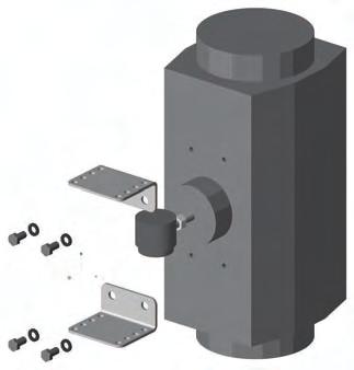
17 Fig. 16 Fig. 17 Fig. 18 IM-P CH Issue 5 17


18 Fig. 19 Assembled Fig IM-P CH Issue 5
19 5.3.2 Adjust the magnet orientation as illustrated in Figures 21 and 22 and tighten the bolt to fix the magnet into position. There should be a distance of between 5 and 14 mm between the magnet and the positioner. Refer to Figure 21 for actuator with clockwise rotation. Refer to Figure 22 for actuator with anti-clockwise rotation. In fact, in this way the magnet movements will always be comprised in the sector between the directions C and D which delimit the operating area of the Hall sensor. D B A Fig. 21 View from the bottom of the positioner - Magnet orientation for clockwise actuator. D B C A Fig. 22 View from bottom of the positioner - Magnet orientation for anti-clockwise actuator. IM-P CH Issue 5 19 C
 and output signal to actuator (output 1 and output 2 for double action applications) as shown in Figure 23. The supply air should be between 1.")
20 5.4 Air supply and connections WARNING: Supply air pressure must not exceed the maximum allowable air pressure of the actuator. Air connections should be ¼" NPT for air supply (supply) and output signal to actuator (output 1 and output 2 for double action applications) as shown in Figure 23. The supply air should be between 1.4 bar g minimum and 6 bar g maximum and be oil and dust free to IEC Mains air supply may sometimes contain traces of dirt, rust, water, oil and other deposits with the potential for contaminating the internals of the positioner. It is therefore essential that a filter / regulator is fitted in the mains air supply to the positioner. The filter / regulator should have a coalescing filter such as a Spirax Sarco type MPC2, or suitable compressed air pipework is used. ¼" NPT air signal to actuator (output 1) Fig. 23 ¼" NPT air supply (supply) 20 IM-P CH Issue 5
21 6. Electrical connections 6.1 Guidance notes on wiring installation For heavy industrial applications it is recommended to use screened cables or signal cables run in metal conduit. Failure to do so could result in positional errors of up to ±5% in an RF field excess of 10 V/m. If screened cables are used, ensure that the screen is connected to the local earth at one end with a connection resistance of less than 1 ohm. For light industrial applications where RF fields do not exceed 3 V/m unscreened cables may be used. Cabling should be installed in accordance with BS Instrumentation in Process Control Systems: Installation design and practice or local equivalent. 6.2 Wiring diagrams Single loop applications (see Section for Multi-loop applications) The SP200 is loop powered using the 4-20 ma input signal source providing a minimum signal of 3.6 ma can be maintained. Minimum current = 3.6 ma Maximum current = 30 ma Voltage drop = ma 5 6 Fig ma signal Multi-loop applications Loop powered multi-positioner connections In a loop powered application, the 4-20 ma signal must be capable of supplying a minimum of 10.6 V per positioner at 20 ma. In a split range application the signal source loop must be capable of supplying sufficient voltage, i.e. 22 V are enough to power 2 positioners (Figure 16). Fig ma signal 22 V minimum - Positioner Positioner In terms of impedance, this means that in split range application, the load in the loop at 20 ma is 1060 Ohm. The impedance of a single SP200 is 530 Ohm at 20 ma. A typical controller might not be able to drive such a impedance load, hence a different approach is required. A 4-20 ma current splitter can provide a solution to this problem for further information please contact Spirax Sarco. IM-P CH Issue 5 21
22 6.2.3 Travel switchesand 4-20 ma retransmission wiring digrams 2 k 1 22 k Travel switches k 3 22 k Travel switches 2 4 Fig. 26 Software switches Example of customers external application wiring ma retransmit - Fig ma retransmit Table 1 Ratings Supply Impedance On current Off current TS1 travel switch Vdc 1.8 k 13 ma 1 24 V TS2 travel switch Vdc 1.8 k 13 ma 1 24 V 4-20 ma 8-30 Vdc IM-P CH Issue 5
23 6.2.4 Wiring for instrinsic safe applications Safe area Hazardous area Digital outputs Switch 1 and Travel switches Barrier (a) Supply 4-20 ma 5 6 Signal Barrier (b) 4-20 ma retransmit 4-20 ma 7 8 Position transmitter Barrier (c) Fig. 28 Example of electrical connections for Intrinsically Safe applications Output parameter for Barrier (b) and (c) Uo 30 V, Io 100 ma, Po 650 mw Output parameter for Barrier (a) Uo 15 V, Io 25 ma, Po 65 mw IM-P CH Issue 5 23
24 7. Quick start procedure port valves The following applies to positioners fitted to 2-port valves having plug above the seat and fitted to pneumatic actuators having a direct acting (DIR) 4-20 ma input signal and excludes the setting of any additional program functions (i.e. default value only). Note: For PN5100 and PN6100 series actuators an additional programming step is required. (Refer to Section 9.5.2) The positioner should be correctly assembled as described in Section 5 and Section 6 and supplied with mains air and signal pipework as described in Section Provide a minimum input signal of 3.6 ma to the positioner. SET-UP NOW should be displayed Ensure that upstream isolation valves are closed. Press and hold key for 3 seconds to advance to SP200 MENU. The display will count down the 3 seconds Press to advance to MANOP Press and hold key for 3 seconds to enter manual control mode MCTL In manual control press and hold or keys to drive the valve stem up or down. Check for any obstructions of valve movement. The display will indicate FILL or VENT as appropriate. Any obstruction should be investigated before proceeding to Section Press key to return to MANOP in main menu Press key to advance to AUTOS autostroke mode Press and hold key for 3 seconds to start the autostroke routine. This will take approximately 2 minutes to complete.! displayed indicates an incomplete or unsuccessful autostroke. The routine can be aborted at any time by pressing key once. If autostroke is aborted during operation ABORT will be displayed and! to indicate incomplete autostroke. On completion the program will automatically return to AUTOS in main menu. A will be displayed if successful autostroke has been completed. It is now possible to advance to RUN in main menu Press key three times to advance to RUN in main menu Press and hold key for 3 seconds to commence automatic operation. The valve will move to a control position related to the input control signal. The percentage valve travel will be displayed %. The positioner cover can now be closed and cover screws tightened. 24 IM-P CH Issue 5
25 7.2 3-port valves (with travel setting (TRAVL) 0-100%, refer to Figures 27 and 28) Proceed as above up to Section On completion of a successful autostroke press the key once to advance to SET in main menu Press key once to advance to VALVE TYPE. Press key to indicate VALVE 3-PORT Press key to select VALVE 3-PORT. Continue to press key to return to SET in main menu Press key twice to advance to RUN in main menu. Proceed as described in Section IM-P CH Issue 5 25
26 8. Programming flow chart Fig. 29 SET-UP NOW Software version (Ver X.XX) SP200 MENU Mounting position check (CALIB) From RETRN (To SP200 MENU) MANOP Manual operation (MCTL) C-CAL % Travel (TRAVL 0-100% / 100-0%) AUTOS Autostroke activate (AUTOS) Note: SET, TUNE, and RUN can only be accessed on completion of a successful autostroke (AUTOS) SET Valve type (VALVE 2-PORT / VALVE 3-PORT) Actuator type (ACT) RETURN (To SP200 MENU) TUNE Dead-band (dband) Shut-off minimum (S-MIN) RUN AUTO OPERATION (% TRAVEL) Return to SP200 menu (RETRN AUTO / RETRN VENT) (RETAIN) (RESET) 26 IM-P CH Issue 5
27 Key 3 seconds enter Clear stored values (RESET) Recall stored values (RETRN) Retain temporary values (RTAIN) Enter Auto return Minimum travel (MIN-T) Maximum travel (MAX-T) Displayed % travel (DTRVL) Minimum range (MIN-R) Maximum range (MAX-R) Only if MIN-T / MAX-T not 0 / 100% Control action (CTRLA) Shut-off maximum (S-MAX) Characterisation (LIN / FAST / EQUAL) Time to open (T-UP) Time to close (T-dWN) AUTO OPERATION (ma Input signal) Stem travel (STRVL) Travel switch 2 (NC) (TS2) Travel switch 1 (NO) (TS1) Run time (RTIME) (RETAIN) (RESET) IM-P CH Issue 5 27
28 9. Programming and commissioning 9.1 Set-up now The positioner fitted to this control valve requires programming. A minimum input signal of 3.6 ma is required to power the positioner. To program the positioner it is necessary to enter SP200 MENU and carry out an autostroke commissioning routine (AUTOS) prior to putting the control valve into automatic operation. A flow chart is included in Section 8 to guide you through the procedure. The display provides a flag indication of the active main menu function. To enter SP200 MENU press and hold key for 3 seconds. The display will count down the 3 seconds. Commissioning notes Main menu functions include: SP200 MENU View software version, mounting position check, reset default values. MANOP AUTOS SET TUNE RUN Manual control of valve movement (Actuator inflation / deflation). Automatic valve commissioning. Provides selection of % travel display. Setting of valve type, control action, travel limits and input signal span. Setting of deadband, tight shut-off, lift characterisation, travel time and software switches. Activates automatic operation plus input signal, total valve strokes and total run time. Also provides route for returning to SP200 MENU. Note: SET, TUNE and RUN functions are restricted and can only be accessed on completion of a successful autostroke routine (AUTOS). 28 IM-P CH Issue 5
29 9.2 SP200 MENU SET-UP NOW 3 seconds enter Software version (Ver X.XX) From RETRN SP200 MENU 3 seconds enter Mounting position check (CALIB) Clear stored values (RESET) Recall stored values (RETRN) Retain temporary values (RTAIN) Fig. 30 You are now in SP200 MENU. SP200 functions include: 1. Visualisation of the embedded software version (VER--). 2. Positional setting (CALIB). 3. Resetting of programmed values to default settings (RESET). 4. To retain settings in the temporary memory (RTAIN). 5. Returning to previously stored settings (RETRN). To check the setting (CALIB) press and hold key for 3 seconds. The display will count down the 3 seconds. CALIB also provides access to RESET / RTAIN / RETRN functions. To view the embedded version of software (VER-.--) press key. To advance to manual operation (MANOP) press key VER -.-- software version To view the version of the embedded software (VER-.--) press key. Press key to return to SP200 MENU. The display will automatically return to SP200 MENU after 10 seconds. IM-P CH Issue 5 29
30 9.2.2 CALIB - mounting position calibration To access CALIB press and hold key for 3 seconds. The display will count down the 3 seconds. You are now in calibrate mode. The LCD shows in % the magnet position in respect to the sensor board of the positioner, without any offset or scale up or down. When the LCD shows 0% the magnet is positioned near the bottom of the positioner s case. At 50% the magnet will be in front of the cross impressed on the back of the positioner. At 100% the magnet will be roughly aligned with the top of the positioner s case. Desired setting is 50% with the valve at half stroke. The and keys can be used to manipulate the actuator inflation. In this way it is possible to check the mounting position and if necessary change it and then check again to get the positioner well centred. Press key advance to RESET / RTAIN / RETRN. 30 IM-P CH Issue 5
31 9.2.3 RETRN - RTAIN - RESET Provides the facility to restore previous permanently stored values (RETRN), to retain values stored in the temporary memory (RTAIN) or to reset all values to factory default settings (RESET). Press and keys to select RETRN, RTAIN or RESET. To advance proceed as follows: RETRN To cancel any temporary changes to programmed values select RETRN and press key to return to SP200 MENU. RTAIN To retain temporary changes to programmed values select RTAIN and press key to return to SP200 MENU. RESET Provides the facility to reset all values to factory default settings and return to SET UP NOW. Press and hold key for 3 seconds. The display will count down the 3 seconds. Commissioning notes RETRN If changes have been made to program values they will be held in the temporary memory. To retain changes in the permanent memory it is necessary to advance to RUN in the main menu and press and hold key for 3 seconds. The display will count down the 3 seconds. If you do not wish to retain temporary changes select RETRN and press key to return to SP200 MENU. RTAIN If changes have been made to programmed values they will be held in the temporary memory. If you wish to retain these changes select RTAIN and press key to return to SP200 MENU. To retain temporary changes in the permanent memory advance to RUN in the main menu and press and hold key for 3 seconds. The display will count down the 3 seconds. RESET Resetting to default values (refer to Section 9 for default values) should be used if it is intended to use the positioner on a different control valve. If the SP200 positioner has been moved on its mounting or is to be fitted on a different control valve it will be necessary to undertake a new autostroke (AUTOS). RESET to factory default settings can also be used if it is required to recommission the valve. To reset to factory default values select RESET and press and hold The display will count down the 3 seconds. key for 3 seconds. IM-P CH Issue 5 31
32 9.3 MANOP MANOP 3 second enter Manual operation (MCTL) C-CAL Fig. 31 Press and hold key for 3 seconds to enter manual control mode (MCTL). The display will count down the 3 seconds. Press the key to enter the current calibration mode (C-CAL). Press to return to MANOP. In MANOP press key to advance to autostroke (AUTOS). Commissioning notes Before initiating an autostroke commissioning (AUTOS) use manual control (MCTL) to manually fully inflate and deflate the actuator to ensure there are no obstructions to the full valve travel movement. Manual control is also useful during normal operation to manually control the valve position as a commissioning aid or in the event of input signal failure MCTL - manual control Manual control enables the actuator to be manually inflated or deflated. Press key to inflate actuator and key to deflate the actuator. Press and hold or key to accelerate action. Prior to undertaking an AUTOS the display will indicate FILL or VENT. On completion of AUTOS the display will indicate % valve travel. Manual control (MCTRL) - Tight shut-off function Press and hold the key to drive the valve to its closed position. At 0% travel the! will flash to indicate limit of travel. To initiate tight shut-off release the key and press again. The actuator will be vented of air to provide dead tight shut-off. This also applies to the 100% valve position by pressing and releasing the key and pressing again to inflate the actuator to provide dead tight shut-off. Manual control (MCTRL) - Travel limits When operating in manual control any travel limit settings will be overridden therefore it is possible to manual position the valve through its full 0 to 100% travel as measured in autostroke (AUTOS). Commissioning notes Before initiating an autostroke commissioning routine (AUTOS) the actuator should be manually fully inflated and deflated to ensure there are no obstructions to the full valve travel movement. Manual control is also useful during normal operation to manually control the valve position as a commissioning aid or in the event of input signal failure. 32 IM-P CH Issue 5
33 9.3.2 C-CAL - current calibration C-Cal provides a simple way to make a fine calibration of the input current signal (4-20 ma). To perform the calibration: 1. Enter C-CAL and press the key, then press the key. 2. Generate a 4 ma input signal and press 3. Generate a 12 ma input signal and press 4. Generate a 20 ma input signal and press If 'ERROR' is displayed the calibration routine is aborted. The value of the generated signal is too far from the expected one. Be sure that a 4 ma, 12 ma or 20 ma signal is generated as required. Press to return to C-CAL. If 'OK' is displayed the calibration has succeeded. Press to return to C-CAL. Where possible current calibration should be overtaken, to guarantee a perfect match between the input current generated and the reading of the SP200. Let s assume that the table below show the input signal generated by a PLC or DCS versus the input signal read by the SP200. Setpoint Input current from PLC Current read from SP200 0% 3.8 ma 3.8 ma 50% 12 ma 12.2 ma 100% 20 ma 20.2 ma Hence when the setpoint is 0% the PLC generates a 3.8 ma instead of 4 ma. After C-CAL is executed the SP200 recalibrates the current read to compensate the error. Setpoint Input current from PLC Current read from SP200 0% 3.8 ma 4 ma 50% 12 ma 12 ma 100% 20 ma 20 ma In this way a perfect match is achieved between the setpoint of the PLC and the setpoint of the of the SP200 (i.e. the input current read by the SP200). IM-P CH Issue 5 33
34 9.4 AUTOS - automatic autostroke commissioning % Travel (TRAVL 0-100% / 100-0%) AUTOS 3 second enter Autostroke activate (AUTOS) Fig. 32 AUTOS provides access to: 1. Autostroke commissioning (AUTOS). 2. % travel display (TRAVL). AUTOS Autostroke provides an automatic commissioning routine which will take approximately 1 to 3 minutes to complete. Press and hold key for 3 seconds to start autostroke. The display will count down the 3 seconds. When autostroke is active a flashing AUTOS message will be displayed. On completion of a successful autostroke the programme will automatically return to AUTOS in the main menu and a will be displayed. In the event of an unsuccessful autostroke routine a flashing! will be displayed. If during AUTOS inconsistent data is obtained due to mechanical problems, the autostroke procedure will be terminated and ABORT will be displayed. It is also possible to immediately abort during an autostroke routine by pressing the key. ABORT will be displayed together with a flashing!. Error messages: ERROR 1 Indicates a wrong mechanical coupling between positioner and actuator. Check the mounting is correct. ERROR 2 Indicates that there is insufficient air pressure to achieve valve movement. Check that the air supply is adequate to overcome the actuator spring force. Fitting of a gauge block will aid the commissioning procedure. ERROR 3 Indicates that the actuator will not deflate. Check that there is no obstruction preventing the stem travel or air venting from the actuator. ERROR 4 indicates that the stroke measured is less than the minimum stroke allowed - 10 mm for linear valves, and 5 for quarter turn valves (output 1 and output 2 for double action applications). ABORT indicates mechanical problems have occurred during the Autostroke procedure or the key has been pressed during Autostroke to abort the procedure. On completion of a successful autostroke it will be possible to advance to SET, TUNE and RUN functions in the main menu. Press the key to advance to these functions. Commissioning notes Prior to undertaking an autostroke routine, manual operation should be used to fully inflate and deflate the actuator to ensure there are no obstructions to the full valve movement. Autostroke is an automatic commissioning routine that checks for maximum valve travel, signal response, valve characteristics, inflation / deflation times etc. Data gathered will be automatically download into the embedded software to ensure optimum performance of the valve / actuator combination. Autostroke commissioning will take approximately 1 to 3 minutes to complete depending on air pressure and actuator size etc. Autostroke commissioning must be carried out on start-up or at any other time if the valve performance is not satisfactory. 34 IM-P CH Issue 5
35 9.4.1 TRAVL - % travel display Press key to access TRAVL. Provides selection of % valve travel display with option of 0-100% or 100-0%. Default is 0-100%. Use and keys to toggle selection. Press key to return to AUTOS. Commissioning notes The selection of % valve travel display depends on the valve and actuator configuration. Figures 33 to 36 (pages 35 and 36), and Figures 37 and 38 (page 37) provide guidance on selection. After completion of AUTOS if a change is made to TRAVL it will be necessary to initiate an AUTOS routine once again. Display = 0% Display = 100% Fig port valve normally closed - TRAVL setting = 0 to 100% Display = 0% Display = 100% Fig port valve normally open - TRAVL setting = 0 to 100% IM-P CH Issue 5 35
36 Display = 100% Display = 0% Fig port valve normally open - TRAVL setting = 100% to 0% Display = 100% Display = 0% Fig port valve normally closed - TRAVL setting = 100% to 0% 36 IM-P CH Issue 5
37 100% 0% TRAVEL setting = 0 to 100% DISPLAY = 0% TRAVL setting = 100 to 0% DISPLAY = 100% TRAVEL setting = 0 to 100% DISPLAY = 100% TRAVL setting = 100 to 0% DISPLAY = 0% 100% 0% Fig port valve and spring extend actuator 100% 0% TRAVEL setting = 0 to 100% DISPLAY = 0% TRAVL setting = 100 to 0% DISPLAY = 100% TRAVEL setting = 0 to 100% DISPLAY = 100% TRAVL setting = 100 to 0% DISPLAY = 0% 100% 0% Fig port valve and spring retract actuator IM-P CH Issue 5 37
38 9.5 SET - setting of valve functions SET Valve type (VALVE 2-PORT / VALVE 3-PORT) Actuator type (ACT) Maximum range (MAX-R) Control action (CTRLA) Minimum range (MIN-R) Minimum travel (MIN-T) Displayed % travel (DTRVL) Maximum travel (MAX-T) Fig. 39 Only if MIN-T / MAX-T not 0 / 100% Provides access to basic valve set up functions. Press SET functions. key to scroll round all Functions include: - Valve type (2-port or 3-port) (VALVE) - Actuator type (on/ off) (ACT) - Control action (direct or reverse) (CTRLA) - Minimum travel setting (0 to 66.66%) (MIN-T) - Maximum travel setting (33.3 to 100%) (MAX T) - Displayed % travel (on/ off) (DTRVL) - Minimum span range (input ma signal) (MIN-R) - Maximum span range (input ma signal) (MAX-R) Press key to advance to valve type (VALVE). Repeat pressing of key will scroll round all SET functions. Press key to advance to TUNE in the main menu. Commissioning notes Each SET function has a default value as listed in the Installation and Maintenance Instructions. Default values are based on a 2-port normally closed valve having maximum 95% lift and an input signal span range 4-20 ma. SET values should be adjusted to suit the valve type (2-port or 3-port) and application. Functions include the facility to change the control action, limit the full travel of the valve plug (minimum and maximum) and to split range the input signal. More detailed information is provided for each SET function. 38 IM-P CH Issue 5
39 9.5.1 VALVE - valve type Provides selection between 2-port and 3-port valves. Default is 2-port valve. Default values for travel limit settings (MIN-T and MAX-T) and early vent / inflate settings (S-MIN and S-MAX) will depend on the valve type (2-port or 3-port) and control action (direct or reverse) as follows: Valve type 2-port 3-port Display Direct Reverse Direct Reverse MIN-T 0% 0% 0% 0% MAX-T 95% 95% % S-MIN 0.1% OFF 0.1% 0.1% S-MAX OFF 0.1% 0.1% 0.1% Use and keys to select type. Press key to accept displayed type and advance to actuator type (ACT). Commissioning notes Selection of 2-port or 3-port valves will automatically alter the maximum travel default value (MAX-T) to 95% for 2-port and 100% for 3-port valves. Advance to MAX-T to change these values if required ACT - actuator type ACT selection is useful to avoid hunting using small actuators like PN5100, PN6100, PN9100 or PN9200 series. Selection is 'ON' or 'OFF'. Default value is 'OFF'. Use the and keys to toggle selection. Press key to accept displayed value and advance to Control action (CTRLA). Selection options: 'OFF' Any pneumatic actuator except when hunting is evident. 'ON' Any small actuator like PN5100, PN6100, PN9100 or PN9200. Commissioning notes Selection of 'ON' automatically adjusts certain programming values to obtain optimum performance for small actuator like type PN5100, PN6100, PN9100 or PN9200 series. ACT doesn t modify parameters set by other functions of the programming menu. When 'ACT' is ON there could be a light speed slow down approaching to the target position. This behaviour doesn t influence SP200 performance and guarantee a positioning without hunting. If a residual hunting or oscillation is present it is possible to operate changing Deadband (dband), Valve opening time (T-UP), Valve closing time (T-dWN). If 'ACT' is 'OFF' standard control values found during Autostroke will be used. IM-P CH Issue 5 39
40 9.5.3 CTRLA - direct or reverse control action Provides selection of direct (dirct) (4-20 ma) or reversed (REV) (20-4 ma) valve positioning control action. Press and keys to select desired action. Default action is dirct. Default values for travel limit settings (MIN-T and MAX-T) and early shut-off vent / inflate settings (S-MIN and S-MAX) will depend on the valve type (2-port or 3-port) and control action (direct or reverse) as follows: DIR - direct action Display 2-port 3-port MIN-T 0% 0% MAX-T 95% 100% S-MIN 0.1% 0.1% S-MAX OFF 0.1% REV - reverse action Display 2-port 3-port MIN-T 0% 0% MAX-T 95% 100% S-MIN OFF 0.1% S-MAX 0.1% 0.1% Press key to accept the displayed action and advance to minimum travel setting (MIN T). Commissioning notes Selection of direct or reverse action changes the direct of valve plug movement relative to the input signal. Refer to Figures 40 and 41, and the table shown in Figure 42 for further guidance. Valve plug position Valve stem lifting Valve plug position Valve stem falling ma Increasing input signal ma Increasing input signal Fig. 40 Direct action (DIR) Fig. 41 Reverse action (REV) 40 IM-P CH Issue 5
41 Fig. 42 CTRL Control Action dirct or REV setting guidance Installed orientation At-rest position Control action 0% (TRAVL) 0-100% 100% 0% (TRAVL) 100-0% Manual Selection of required % travel (TRAVL) 100% Automatic determintation Spring action only affects the rest or fail-safe position Manual Selection of required Control Action (CTRLA) IM-P CH Issue 5 41
42 9.5.4 MIN-T - minimum travel setting Enables the minimum valve travel to be set as a percentage of the maximum travel obtained during autostroke. Maximum setting is MAX-T less 33.3%. Default value is 0%. Use and keys to alter the displayed value. Press key to accept the displayed value and advance to the maximum travel setting (MAX-T). Commissioning notes Minimum travel should be used where a minimum flowrate is required to be maintained through the valve, (i.e. a cooling water application). Setting a minimum travel % value will prevent the valve fully closing. The input signal span range set (MIN-R) and (MAX-R) will operate over the travel limits set. If a value for MIN T is set it will exclude the setting of shut-off minimum (S-MIN) for control action direct (DIR) and shut-off maximum (S-MAX) for control action reverse (REV) MAX-T - maximum travel setting Enables the maximum valve travel to be set as a percentage of the maximum travel measured during autostroke. Minimum setting is MIN-T plus 33.3%. Default values will depend on the selection of valve type (2-port or 3-port) and control action (direct or reverse) as follows: Valve type Direct Reverse 2-port 95% 95% 3-port 100% 100% Use and keys to adjust the displayed value. Press key to accept displayed value and advance to the next function. Commissioning notes The maximum valve travel percentage should be used to prevent a control valve fully opening. This is useful for applications where the valve is oversized or to restrict the maximum flowrate through the valve. On 2-port valves the default value is 95% to prevent the back of the plug hitting the bonnet. On 3-port valves to ensure shut-off on both seats a 100% setting is required. The input signal span range set (MIN-R) and (MAX-R) will operate over the travel limits set. If a value for MAX-T is set it will exclude the setting of shut-off maximum (S-MAX) for direct action (DIR) and shut-off minimum control action (S-MIN) for reverse action (REV). 42 IM-P CH Issue 5
43 9.5.6 DTRVL - displayed travel percentage The full mechanical limits of valve travel (0 to 100%) are measured during autostroke (AUTOS). It is possible to limit the minimum and maximum valve travel by programming MIN-T and MAX-T values, i.e. MAX-T maximum travel limit of 95% (Autostroke default value for 2-port valves). DTRVL (0 to 100% displayed travel value) can be displayed over the actual mechanical travel limits (as measured during Autostroke), or adjusted MIN-T and MAX-T travel settings. DTRVL programming options DTRVL - ON will display 0 to 100% over the MIN-T and MAX-T travel settings, or, DTRVL - OFF will display 0 to 100% over the actual mechanical limits of travel. Default value is DTRVL - ON. Use and keys to toggle selection. Press key to accept displayed 'ON' or 'OFF' option and advance to minimum range setting (MIN-R). Examples Example 1 Example 2 MAX-T = 95% MAX-T = 95% MIN-T = 0% MIN-T = 5% Display values DTRVL - ON DTRVL - OFF 100% 95% 0% 0% Display values DTRVL - ON DTRVL - OFF 100% 95% 0% 5% Commissioning notes DTRVL provides the choice of travel display. For 2-port valves you can adjust the MAX-T setting to achieve the actual desired valve lift (i.e. 20 mm or 30 mm, etc). Using DTRVL you can then choose to display the MAX-T valve travel you have set as 100%. IM-P CH Issue 5 43
44 9.5.7 MIN-R - minimum signal span range Enables the minimum ma input signal span range to be set. The value set will correspond to the minimum travel setting. Default value is 4 ma. Use and keys to alter the displayed value. Minimum difference between MIN-R and MAX-R is 4 ma. Press key to accept the displayed value and advance to the maximum ma input span range (MAX-R). Commissioning notes This function can be used to set split range applications i.e ma or ma. To ensure tight shut-off refer to Section S-MIN, page MAX-R - maximum signal span range Enables the maximum ma input signal span range to be set. The value set will correspond to the maximum travel setting. Default value is 20 ma. Use and keys to alter the displayed value. Minimum difference between MIN-R and MAX-R is 4 ma. Press key to accept the displayed value and return to SET in the main menu. Commissioning notes This function can be used to easily set split range applications i.e ma or ma. To ensure tight shut-off refer to Section S-MAX, page IM-P CH Issue 5
45 9.6 TUNE - setting of valve tune functions TUNE Dead-band (dband) Shut-off minimum (S-MIN) Travel switch 2 (TS2) Normally closed Shut-off maximum (S-MAX) Travel switch 1 (TS1) Normally open Characterisation (LIN / FAST / EQUAL) Time to close (T-dWN) Time to open (T-UP) Fig. 42 Provides access to more advanced valve tuning functions including: - Dead-band (valve positioning sensitivity) (dband) - Shut-off minimum (ensures tight closure) (S-MIN) - Shut-off maximum (ensures tight closure) (S-MAX) - Characterisation (signal / lift relationship) (CHAR) - Time open (slows down valve opening) (T-UP) - Time close (slows down valve closure) (T-dWN) - Travel switch 1 normally open (sets software travel switch) (TS1) - Travel switch 2 normally closed (sets software travel switch) (TS2) Press key to advance to deadband (dband). Repeated pressing of key will scroll round all TUNE functions. If you do not wish to alter TUNE default values press key to advance to RUN in the main menu. Commissioning notes Each TUNE function has a default value as listed in the Installation and Maintenance Instructions. Default values are based on a 2-port normally closed valve having maximum 95% lift and an input signal span range 4-20 ma. TUNE values should be adjusted to suit the valve type and application. Functions include: 1. The facility to alter deadband positioning sensitivity (to dampen out signal fluctuations). 2. Setting input signal to achieve tight shut-off (inflation and deflation of actuator). 3. Relationship between valve lift to input signal. 4. Slowing down the valve open or closing time duration. 5. Setting the switching position for the software travel switches. More detailed information is provided for each TUNE function. IM-P CH Issue 5 45
46 9.6.1 dband - deadband setting (positional sensitivity) Dead-band provides adjustment of the valve positioning sensitivity relative to the input signal and is expressed as a % of the input signal span. Default value based on a 4-20 ma input signal span is 0.5% with a minimum setting of 0.2%. Note: 3% may be displayed if ACT is set to 'ON'. Refer to Section 9.5.2, page 39. These values may change if the input signal span is reduced i.e. for a 4 ma input signal span the default and minimum setting is 0.8%. The maximum setting is 10% of the input signal span. To alter the displayed value press and keys. Press key to accept the displayed value and advance to the shut-off minimum (S-MIN). Commissioning notes Setting a narrow deadband may induce oscillations of valve movement caused by fluctuations in the input signal, high stem friction or operating at low ambient temperatures below 0 C. Setting a wider deadband will dampen out oscillations but may cause an inaccuracy in actual valve position. This effect will increase if valve travel is limited. It is normally recommended that the default value is used. If necessary gradually increase the % value to dampen out any oscillations in valve movement. This may be necessary for valves having graphite packed stem seals or smaller size actuators where typically a deadband of 4% may be required S-MIN - valve shut-off - minimum travel Provides the facility to fully vent the actuator at a predetermined input signal. The value set is a percentage of the input signal span range, i.e. setting a value of 10% with an input span range of 4-20 ma (span 16 ma), will cause the valve to close with an input signal of 5.6 ma i.e. 4 ma ma (10% of 16 ma). Maximum setting is 20%. Default values will depend on the selection of valve type (2-port or 3-port) and control action (direct or reverse) as follows: Valve type Direct Reverse 2-port 0.1% Off% 3-port 0.1% 0.1% For direct control action (dirct) can only be set if MIN-T = 0% (will vent the actuator at set value). For reverse action (REV) can only be set if MAX-T = 100% (will inflate the actuator at set value). Press and keys to alter the displayed value. Press key to accept the displayed value and advance to shut-off maximum (S-MAX). Commissioning notes With an actual input signal equivalent to minimum input signal span range (MIN-R) it may cause the valve plug to hover over the seat preventing tight closure with the possibility of erosion damage to the plug and seat faces. Setting a shut-off value can help prevent this by providing early closure of the valve. 46 IM-P CH Issue 5
47 9.6.3 S-MAX - valve shut-off maximum Provides the facility to fully inflate the actuator at a pre-determined input signal. The value set is a percentage of the input signal span range, i.e. setting a value of 10% with an input span range of 4-20 ma (16 ma), will cause the valve to close with an input signal of 18.4 ma i.e. 20 ma ma (10% of 16 ma). Maximum setting is 20%. Default values will depend on the selection of valve type (2-port or 3-port) and control action (direct or reverse) as follows: Valve type Direct Reverse 2-port Off 0.1% 3-port 0.1% 0.1% For direct action (dirct) can only be set if MAX-T = 100% (will inflate the actuator at set value). For reverse action (REV) can only be set if MIN-T = 0% (will vent the actuator at set value). Press and keys to alter displayed value. Press key to accept the displayed value and advance to the characterisation (CHAR). Commissioning notes With an actual input signal of 20 ma and a maximum span range setting (MAX-R) of 20 ma may cause the valve plug to hover over the seat preventing tight closure with the possibility of erosion damage to the plug and seat. Setting a shut-off value can help prevent this by providing early closure of the valve CHAR - valve characterisation Provides selection of linear (LIN), equal percentage (EQUAL) or fast opening (FAST) characterisation. Characterisation is the relationship between input signal and valve lift. Default value is Linear (LIN). Use and keys to select the desired action. Press key to accept the displayed characterisation and advance to time open (T-UP). Commissioning notes The standard characterisation for 2-port and 3-port valves is linear (LIN). For special applications using 2-port valves an equal percentage (EQUAL) or fast opening (FAST) characteristic can be selected. With equal percentage the valve will start to open slowly and gradually accelerate opening related to input signal. With fast opening characteristic the valve will commence to open quickly and gradually slow down opening related to the input signal. This action is in addition to the valve trim flow characterisation (refer to Figure 43 for guidance). Ratio 1:1 Ratio 1:50 Ratio 50:1 Valve lift Valve lift Valve lift Fig. 43 Signal (ma) Signal (ma) Signal (ma) IM-P CH Issue 5 47
48 9.6.5 T-UP - valve slow opening action This function slows down the time taken for the valve to travel from 0 to 100% lift. The time displayed is the fastest travel time measured during autostroke (AUTOS). 4 seconds may be displayed if ACT is set to 'ON' (refer to Section 9.5.2, page 39). Default value is the fastest time measured during autostroke. Press and keys to alter the displayed value. Press key to accept the displayed value and advance to time down (T-dWN). Commissioning notes The time displayed on start-up is the fastest time measured during autostroke commissioning (AUTOS). A time cannot be set less than the minimum recorded during autostroke. The value set will be the time taken for the valve to travel from 0 to 100% lift. The time set will apply at all times and not just at start-up. This function is useful to prevent the effects of system waterhammer, thermal shocks or slow down over-reactive systems or the effects of oversized valves. Default is the fastest time measured during autostroke. Maximum setting is 180 seconds T-dWN - valve slow closing action This function slows down the time taken for the valve to travel from 100 to 0% lift. The time displayed on start-up is the fastest travel time measured during autostroke (AUTOS). 4 seconds may be displayed if ACT is set to 'ON' (refer to Section 9.5.2, page 39). Default value is the fastest time measured during autostroke. Press and keys to alter the displayed value. Press key to accept the displayed value and advance to travel switch 1 (TS1). Commissioning notes During autostroke routine the quickest time taken for the valve to fully close will be measured and displayed. A time cannot be set less than the minimum recorded during autostroke. The value set will be the time taken for the valve to travel from 100 to 0% lift. This action will apply at all times and not just at start-up. This function is useful to prevent the effects of system waterhammer, or to slow down over-reactive systems or the effects of oversized valves. Default is the minimum time measured during autostroke. Maximum setting is 180 seconds. 48 IM-P CH Issue 5
49 9.6.7 TS1 and TS2 software travel switches Two switches are available TS1 and TS2. TS1 is normally open and TS2 is normally closed. Switching action is set as a % of valve travel (refer to Figures 44 and 45). TS1 - software configured travel switch 1 (normally open) The switching point can be set as a percentage of the valve travel between 0 to100%. A value can be set outside the limits of the travel settings (MIN-T) and (MAX-T). Initially OFF will be displayed indicating that the switch is not set. To set a switching point press and keys to alter the displayed value. Press key to accept the displayed value and advance to travel switch 2 normally closed (TS2). Commissioning notes Travel switch 1 (TS1) is normally open. External wiring should be made between terminals 1 (+) and 2 (-). The value set is a % of valve travel. At the set value the switch will close. The status of the switch will be shown on the LCD (refer to Figure 44). Software configured travel switches can be used to remotely indicate valve position or to operate warning devices, fans, stirrers, motors or other process equipment via a secondary switching device. Switch closed Switch open Travel 100% 50% 0% Note: Software configured travel switches can be set within the range 0% to 100% of full travel irrespective of any travel limit settings. Signal Fig. 44 TS1 Travel switch 1 (normally open) IM-P CH Issue 5 49
50 TS2 - software configured travel switch 2 (normally closed) The switching point can be set as a percentage of the valve travel between 0 to 100%. A value can be set outside the limits of the travel settings (MIN-T) and (MAX-T). Initially OFF will be displayed indicating that the switch is not set. To set a switching point press and keys to alter the displayed value. Press key to accept the displayed value and return to TUNE in the main menu. Commissioning notes Travel switch 2 (TS2) is normally closed. External wiring should be made between terminals 3 (+) and 4 (-). The value set is a % of valve travel. At the set value the switch will open. The status of the switch will be shown on the LCD (refer to Figure 45). Software configured travel switches can be used to remotely indicate valve position or to operate warning devices, fans, stirrers, motors or other process equipment via a secondary switching device. Note: If the switch is in its 'off' status it will be an open circuit. Switch open Switch closed Travel 100% 50% 0% Note: Software configured travel switches can be set within the range 0% to 100% of full travel irrespective of any travel limit settings. Signal Fig. 45 TS2 Travel switch 2 (normally closed) 50 IM-P CH Issue 5
51 9.7 RUN - automatic operation RUN AUTO OPERATION (% TRAVEL) ma (ma input signal) Return to SP200 MENU Return to SP200 menu (RETRN AUTO / RETRN VENT) (RETAIN) (RESET) Run time (RTIME) Stem travel (STRVL) (RETAIN) (RESET) Fig. 46 Provides the facility to put the valve into automatic operation. Press and hold key for 3 seconds to start automatic operation. The display will count down the 3 seconds. The valve will move to a position in response to the input control signal. All values stored in the temporary memory will be transferred to the permanent memory. Commissioning notes By pressing and holding the key for 3 seconds all values previously set will be entered into the permanent memory. The valve will move to a position as dictated by the input control signal. To alter or check SET or TUNE values it is necessary to return to SP200 MENU. Press and hold key for 3 seconds to return to SP200 MENU. The display will count down the 3 seconds. There are two options for returning to SP200 MENU: Option 1 is to stay in automatic control (AUTO) where the valve will continue to position itself relative to the input control signal. Option 2 is to vent the actuator (VENT) where the valve will travel to its fail-safe position. IM-P CH Issue 5 51
52 9.7.1 Automatic operation - % travel During normal automatic operation the % valve travel will be continuously displayed together with the switch status of the software travel switches (if fitted). Additionally, a will be displayed indicating that the valve is operating satisfactorily. At any time during automatic operation the ma input signal can be displayed by pressing key. To return to SP200 MENU press and hold key for 3 seconds. The display will count down the 3 seconds. You will advance to RETRN with the option of AUTO (automatic operation) or VENT (venting air from actuator). Use and keys to select the desired option. Press key to accept the displayed option and return to SP200 MENU. Commissioning notes During normal operation the % valve travel will be continually displayed. A indicates that the valve is performing satisfactorily. Causes of fluctuations in valve movement can be related to input signal. Press key to view actual ma input signal Input signal - ma signal display The ma input signal will be displayed. Press key to return to displaying % travel. The programme will automatically return to displaying % travel after 5 minutes. It is possible to advance to view valve diagnostics data STRVL (total valve strokes) and RTIME (total run time). To advance to STRVL press and hold key for 3 seconds. The display will count the 3 seconds. Commissioning notes This function is of assistance to visualise and check input signal relative to valve position and to investigate causes of fluctuations in valve movement. The ma input signal will be displayed for 5 minutes. Press key to return to displaying % travel. The programme will automatically return to displaying % travel after 5 minutes. 52 IM-P CH Issue 5
53 9.8 STRVL and RTIME - valve diagnostics Provides visibility of total number of valve strokes (STRVL) and total valve run time in hours (RTIME) STRVL - total stem travel The number displayed should be multiplied by a factor of 10 to obtain the total number of complete valve strokes. A complete valve stroke is as measured in autostroke AUTOS. The number displayed can be retained (RTAIN) or reset to zero (RESET). Press the key to advance to RTAIN / RESET. Press and keys to toggle selection. Press key to accept the displayed selection and advance to run time RTIME. Commissioning notes Information displayed should be used in conjunction with total runtime RTIME to assess the valve usage and evaluate the need for routine maintenance, replacement of stem seals etc. The number displayed should be multiplyed by a factor of 10 to obtain the local total number of complete valve strokes. (A complete valve stroke is as measured in autostroke (AUTOS)). The maximum possible display value is If this value is exceeded, the display will roll over to zero and an! will be displayed. To retain the displayed value press the enter key and select RTAIN. If the valve is dismantled for maintenance inspection etc. The value can be reset if required by selecting RESET RTIME - total valve run time in hours The number displayed is the total valve run time in hours. Run time is defined as the total time the positioner is receiving a control signal. The number displayed can be retained (RTAIN) or reset to zero (RESET). Press the key to advance to RTAIN / RESET. Press and keys to toggle selection. Press key to accept the displayed selection and return to displaying % travel. Commissioning notes Information displayed should be used in conjunction with total valve strokes (STRVL) to assess the valve usage and evaluate the need for routine maintenance, replacement of stem seals etc. To retain the displayed value press key and select RTAIN. If the valve is dismantled for maintenance inspection etc. The value can be reset to zero if required by selecting RESET. IM-P CH Issue 5 53
54 9.9 RETRN - return to SP200 MENU in main menu Return to SP200 MENU Fig. 47 Return to SP200 menu (RETRN AUTO / RETRN VENT) AUTO OPERATION (% TRAVEL) Press and hold key for 3 seconds. The display will count down the 3 seconds. This provides the facility to return to SP200 MENU with the option of staying in automatic operation (AUTO) or venting the actuator (VENT). Use and keys to toggle selection. Press key to select and return to SP200 MENU. Commissioning notes To alter any SET or TUNE values, go into manual control (MCTL) it is then necessary to return to the SP200 MENU. Any values altered will be recorded in the temporary memory and activated immediately. To store in the permanent memory it will be necessary to advance to RUN and press and hold key for 3 seconds. The display will count down the 3 seconds. To return to the main menu but stay in automatic control select AUTO. The valve will continue in automatic operation and respond to changes in input control signal. With the exception of CALIB and MCTL functions, main menu and subroutines will timeout after 5 minutes if no key is pressed and revert to displaying % TRAVEL in automatic control mode. Any temporary changes made will not be recorded in the permanent memory. To return to main menu in a fail-safe position select VENT. The actuator will be fully vented of air and the valve will return to its fail-safe position. To return to manual control (MCTL) advance to MANOP in the main menu and advance to manual control (MCTL). The valve can now be manually controlled using the and keys to inflate or deflate the actuator. The desired % TRAVEL will be displayed. To return to automatic control advance to RUN and press key for 3 seconds. The display will count down the 3 seconds. The valve will revert to automatic control and position itself relative to the input control signal. Any SET or TUNE values altered will be recorded in the permanent memory. 54 IM-P CH Issue 5

55 10. Maintenance 10.1 Air supply quality As stated in Section 5.4, it is important for correct operation of the SP200 positioner that good quality air is supplied. It is therefore recommended that a Spirax Sarco MPC2 filter regulator or equivalent is fitted on the air supply to the positioner. In addition the SP200 positioner has an internal filter. In normal operation it is recommended that this filter is replaced every 6 to 12 months depending on the air quality and valve usage. A spare filter plug kit can be obtained from Spirax Sarco that includes: filter plug, plus 3 off 'O' rings and filter Fitting replacement filter plug kit To change the filter proceed as follows: - Ensure that the air supply to the positioner is isolated. - Unscrew the filter plug (1) from the SP200 housing using a 5 mm allen key (refer to Figure 48). The replacement filter plug can now be fitted: - Fit the 'O' ring (4) and filter (3) onto the filter plug (1) (refer to Figure 49). - Finally fit the retaining screw (2). The filter plug can now be replaced into the SP200 housing, checking that the 'O' ring (4) is correctly located. The pnuematic air supply can now be restored to the positioner and checks made to ensure that the filter plug 'O' ring has provided the neccesary air tight seal. Fig. 48 Filter plug (1) 2 3 Fig IM-P CH Issue 5 55
56 11. Default values and program settings Main menu Sub-menu Setting options Default value Programmed value SET SET SET SET SET SET SET SET TUNE TUNE TUNE TUNE Valve type 2-PORT (VALVE) 3-PORT Actuator type ON (ACT) OFF Control action Direct (dirct) (CTRLA) Reverse (REV) Minimum travel (MIN-T) (2-PORT) OFF (dirct) 0 to 66% 0% Maximum travel 33 to 100% 95% for 2-port (MAX-T) 100% for 3-port Displayed % travel ON (DTRVL) OFF Minimum input signal (MIN-R) Maximum input signal (MAX-R) Dead-band (dband) Minimum shut-off OFF, (S-MIN) 0 to 20% ON 4 to 16 ma 4 ma 8 to 20 ma 20 ma 0.2 to 10% 0.5% (% of (3% if input signal span) ACT is 'ON') 0.1% Maximum shut-off OFF, OFF for 2-port (S-MAX) 0 to 20% 0.1% for 3-port Characteristic (CHAR) Linear (LIN), Equal (EQUAL), Fast (FAST) (LIN) Autostroke time Time-up Autostroke time (seconds) TUNE (T-UP) 180 seconds 4 seconds if ACT is 'ON' Autostroke time Time-down Autostroke time (seconds) TUNE (T-dWN) 180 seconds 4 seconds if ACT is 'ON' TUNE TUNE RUN Travel switch 1 OFF, (TS1) 0 to 100% Travel switch 2 OFF, (TS2) 0 to 100% Return to menu Auto (RETRN AUTO) Vent (RETRN VENT) (TS1 OFF) (TS2 OFF) (RETRN AUTO) 56 IM-P CH Issue 5
57 12. Glossary of display data 12.1 Main menu display functions Display SET UP NOW SP200 MENU MAN OP AUTOS SET TUNE RUN Description Indicates that the SP200 positioner fitted to the valve has not been programmed or commissioned. Indicates that you have now entered the SP200 main menu. Provides access to: View the version of the embedded software. Facility to centre the mounting position (CALIB). Retain temporary changes to menu values (RETRN). Recall previously stored menu values (RTAIN). Reset to default values (RESET). Provides access to manual control (MCTL) and current calibration (C-CAL). Provides access to: Autostroke commissioning routine. Note: SET, TUNE and RUN functions can only be accessed after a successful AUTOSTROKE routine has been completed. Selection of percentage travel display % (TRAVL). Provides access to valve set up functions as follows: Valve type (VALVE). Actuator type (ACT). Control action (CTRLA). Minimum valve travel (MIN-T). Maximum valve travel (MAX-T). Displayed % travel (DTRVL). Minimum signal range (MIN-R). Maximum signal range (MAX-R). Provides access to additional valve characterisation functions as follows: Dead-band sensitivity (dband). Valve shut-off minimum setting (S-MIN). Valve shut-off maximum setting (S-MAX). Valve signal lift characterisation (CHAR). Valve slow opening time (T-UP). Valve slow closing time (T-dWN). Setting software travel switch 1 (normally open) (TS1). Setting software travel switch 2 (normally closed) (TS2). Provides access to: Commencing automatic operation. Displaying percentage valve travel (%). Visualisation of input ma input signal (ma). Total stem strokes (STRVL). Total running time (RTIME). Return to SP200 menu (RETRN). IM-P CH Issue 5 57
58 12.2 Sub-menu display functions Display VER x.xx CALIb RETRN RTAIN RESET MCTL C-CAL TRAVL AUTOS AbORT VALVE ACT CTRLA MIN-T MAX-T DTRVL MIN-R MAX-R dband S-MIN S-MAX CHAR LIN Description Indicates the version of software embedded within the SP200 positioner. Provides facility for mounting position adjustment. Enables previously stored function values to be recalled. Enables temporary changes made to function values to be retained. Enables all function values to be reset to default settings. Refer to Section 11 for default settings. Provides manual control of the valve. Use and keys to fill or vent the actuator. Calibration of the current input. Selection of percentage of travel display - 0 to 100% or 100 to 0% depending on valve and actuator configuration. Initiates the autostroke automatic commissioning routine. Indicates that the AUTOS commissioning routine has been aborted. Selection of 2-port or 3-port valve. Selection for use with PN5100 or PN6100 series pneumatic actuators. Selection of input signal control action 4-20 ma or 20-4 ma. Setting of minimum valve travel % to prevent the valve fully closing. Selection of maximum valve travel % to prevent the valve fully opening. Selection of displaying 0-100% travel over the mechanical travel limits or adjusted MIN-T / MAX-T settings. Selection of the input signal related to the minimum valve travel (MIN-T). Selection of the maximum input signal related to maximum valve travel (MAX-T) Selection of % valve position dead-band sensitivity. Facility to select pre-determined input signal to fully close the valve at the minimum travel position. Facility to select a pre-determined input signal to fully close the valve at the maximum travel position. Selection of input signal to valve lift characterisation. Options include: Linear (LIN) Equal percentage (EQUAL) Fast opening (FAST) Indicates a linear relationship between the input signal and the valve travel. 58 IM-P CH Issue 5
59 Display Description EQUAL FAST T-UP T-dWN TS1 TS2 % ma AUTOC FILL! ERROR 1 (AUTOS) ERROR 2 (AUTOS) ERROR 3 (AUTOS) ERROR 4 (AUTOS) Indicates an equal percentage relationship between the input signal and the valve travel. Indicates a fast opening relationship between the input signal and the valve travel. Facility to slow down the valve opening movement. Facility to slow down the valve closing movement. Setting of % travel for software travel switch 1 (normally open). Setting of % travel for software travel switch 2 (normally closed). Indicates percentage of valve travel in automatic operation or manual control (MCTL). Indicates the input signal in ma. Return to SP200 MENU remaining in automatic control operation. Indicates the actuator is being filled with air (manual control before AUTOS). Indicates that there are no problems with the positioner. An error or warning indication. Indicates a problem with the mounting position. Indicates that there is insufficient air pressure to position the valve. Indicates that the air cannot be vented from the actuator. Detected stroke too short. Software travel switch (TS1 and TS2) - closed. / Software travel switch (TS1) - open. \ Software travel switch (TS2) - open. STRVL Indicates the total number of valve strokes (x10). Value can be retained (RTAIN) or reset (RESET). RTIME Indicates the total run time of the SP200 in hours. Value can be retained (RTAIN) or reset (RESET) IM-P CH Issue 5 59
 60 IM-P343-29")
60 13. Certification EC-Type ATEX Certificate (Model SP200is) 60 IM-P CH Issue 5
EP500 Advanced ATEX Electropneumatic Positioner
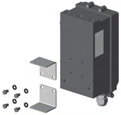
 3.568.5275.306 IM-P343-46 CH Issue 2 EP500 Advanced ATEX Electropneumatic Positioner Installation and Maintenance Instructions 1. Safety information 2. Technical Information 3. Installation 4. Commissioning
Electropneumatic Positioner and Pneumatic Positioner Type 3760 JIS
 Electropneumatic Positioner and Pneumatic Positioner Type 3760 Application Single-acting positioners for direct attachment to pneumatic control valves. Supplied with an electric input signal of 4 to 20
Electropneumatic Positioner and Pneumatic Positioner Type 3760 JIS
 Electropneumatic Positioner and Pneumatic Positioner Type 3760 Application Single-acting positioners for direct attachment to pneumatic control valves. An electric standardized signal of 4 to 20 ma or
Magnetic level switch type MR783 Instruction Manual
 Magnetic level switch Magnetic level switch type MR783 1. DESCRIPTION page 3 1.1 Operation page 3 1.2 Application page 3 1.3 Description page 3 2. SPECIFICATIONS page 3 2.1 Service Conditions page 4 2.2
SSR. Smart Valve Positioner.
 Smart Valve Positioner Smartest valve control device meeting a dynamic performance and a precise setting with a piezoelectric technology and an optimized auto-calibration program Features Auto-Calibration
I/P Transducer Positioner Module
 I/P Transducer Positioner Module VRC P/N: 7958032 Installation, Operation and Maintenance Instructions 2.09 [53.1] 1.30 [32.9] 2.97 [75.5] 0.78 [19.8] 0.18 [4.4] 1.42 [36.1] n.18 MOUNTING HOLES (2) PLACES
SSL. Smart Valve Positioner.
 Smart Valve Positioner Smartest valve control device meeting a dynamic performance and a precise setting with a piezoelectric technology and an optimized auto-calibration program Features Auto-Calibration
Electropneumatic Positioner Type 4763 Pneumatic Positioner Type 4765
 Electropneumatic Positioner Type 4763 Pneumatic Positioner Type 4765 Application Single-acting positioner for attachment to pneumatic control valves. Supplied with either an electric input signal from
Smart performance with innovative and ever-strong coil drive even under harsh working environments
 Smart Valve Positioner SS2 inear / Rotary Smart performance with innovative and ever-strong coil drive even under harsh working environments Easy and quick auto-calibration Detecting RA (reverse acting)
Electro-Pneumatic Converter YT-940 SERIES
 Electro-Pneumatic Converter YT-940 SERIES PRODUCT MANUAL VERSION 1.00 Contents 1. Introduction 3 1.1 General information for the users. 3 1.2 Manufacturer Warranty 3 1.3 Explosion Proof Warning. 4 2. Product
Electropneumatic Transducer (I/P) Installation, Operation and
 Installation, Operation and") Nitra NCP1 Series Electropneumatic Transducer (I/P) Installation, Operation and Maintenance Instructions Ordering Information Contents Part Number I/P Transducers Output Range Input psig bar Section Description
Nitra NCP1 Series Electropneumatic Transducer (I/P) Installation, Operation and Maintenance Instructions Ordering Information Contents Part Number I/P Transducers Output Range Input psig bar Section Description
Torque Tube TB300 Digital Transmitters
 Page 1 of 7 7E.300-E Issue 4-2009 Description Series TB300 torque tube liquid level instruments utilize the buoyancy exerted on a displacer when immersed in a liquid. The buoyancy on the displacer is proportional
The Ins and Outs of I/P Transducers
 The Ins and Outs of I/P Transducers By Mark B. Levine, ControlAir Inc. General description I/P transducers are versatile instruments that use an electrical control signal to proportionally regulate gas
OSAT Series. Intrinsically Safe Infrared Temperature Sensor Operator's Guide
 OSAT Series Intrinsically Safe Infrared Temperature Sensor Operator's Guide Issue L Jan 2017 Introduction OSAT Series intrinsically safe non-contact infrared temperature sensors measure the temperature
RC 195 Receiver-Controller
 Document No. 129-082 RC 195 Receiver-Controller Product Description The POWERS RC 195 Receiver-Controller is a pneumatic instrument that receives one, two or three pneumatic inputs. It produces a pneumatic
Model 130M Pneumatic Controller
 Instruction MI 017-450 May 1978 Model 130M Pneumatic Controller Installation and Operation Manual Control Unit Controller Model 130M Controller is a pneumatic, shelf-mounted instrument with a separate
Operating instructions Safety Rope Emergency Stop Switches ZB0052 / ZB0053 ZB0072 / ZB0073
 Operating instructions Safety Rope Emergency Stop Switches UK ZB0052 / ZB0053 ZB0072 / ZB0073 7390878 / 02 03 / 2011 Contents 1 Safety instructions...3 2 Installation / set-up...4 2.1 Applications...4
ellison sensors international
 PR3900 HAZARDOUS AREA PRESSURE TRANSMITTER ATEX CERTIFIED AND ALL EQUIVALENTS FOR HAZARDOUS AREAS: ZONE 0 GAS GROUP IIC, TEMPERATURE CLASS T4 AND ZONE 20 DUST PROTECTION BY INTRINSIC SAFETY TO EEXIA IIC
FLAMMABLE GAS SENSOR/TRANSMITTER
 FLAMMABLE GAS SENSOR/TRANSMITTER Plant safety protection for flammable gases. F E A T U R E S Fixed gas monitoring for point source hazards and perimeter protection in arduous duty and exposed locations.
Micro Motion 3098 Gas Specific Gravity Meter
 Product Data Sheet PS-001188, Rev. B April 2009 Micro Motion 3098 Gas Specific Gravity Meter Micro Motion density and concentration meters are built to tackle the most demanding process and fiscal applications.
Engineering Data Sheet
 Page 1 of 6 CE MARKING AND THE PRESSURE EQUIPMENT DIRECTIVE 97/23/EC Valves must be installed into a well designed system and it is recommended that the system be inspected in accordance with the appropriate
M111 Spiraflo Transducer
 3309551/ 7 IM-P330-38 MI Issue 7 M111 Spiraflo Transducer Installation and Maintenance Instructions 1. Safety information 2. General product information 3. Technical data 4. Mechanical installation: M111
User s Manual EJX/EJA-E Series NEPSI Certification [Option code: /NF2, /NS21, /NS24 and /NS25] IM 01C25A00-12E
![User s Manual EJX/EJA-E Series NEPSI Certification [Option code: /NF2, /NS21, /NS24 and /NS25] IM 01C25A00-12E](/thumbs/86/93658860.jpg "User s Manual EJX/EJA-E Series NEPSI Certification [Option code: /NF2, /NS21, /NS24 and /NS25] IM 01C25A00-12E") User s Manual EJX/EJA-E Series NEPSI Certification [Option code: /NF2, /NS21, /NS24 and /NS25] 12th Edition 1 1. Introduction Thank you for purchasing the DPharp electronic pressure transmitter. This manual
User s Manual EJX/EJA-E Series NEPSI Certification [Option code: /NF2, /NS21, /NS24 and /NS25] 12th Edition 1 1. Introduction Thank you for purchasing the DPharp electronic pressure transmitter. This manual
QPL... Pressure Switches. Siemens Building Technologies HVAC Products
 7 221 Pressure Switches QPL... The pressure switches are used for monitoring gas or air pressures. When the pressure falls below the switching point, the associated electrical circuit will open or switch
Manual Actuated Boiler Blowdown Valves
 Manual Actuated Boiler Blowdown Valves Installation and Maintenance Instructions 1. Safety information 2. General product information 3. Installation 4. Operation 5. Maintenance 6. Spare parts p.1 1. Safety
Air Sensor. FCS Ex. Manual. AQ Elteknik AB
 Air Sensor FCS Ex Manual AQ Elteknik AB Air Sensor Model FCS Ex Manual version 2.0 Oct 2010 AQ Elteknik AB AQ Elteknik AB Air Sensor Manual 2 Table of contents 1. Manufacturer information... 4 Manufacture
Operating Instructions Part No
 DIGITAL AUTOMATIC TYRE INFLATOR Operating Instructions Part No. 11.0545 Thank you for selecting this Jamec Pem Automatic Tyre Inflator. Please read this manual before carrying out any installation or service
Richards Industries Basic Siemens PS2 Positioner Functions
 Basic Siemens PS2 Positioner Functions Wiring 1 Supply Pressure Use clean, dry instrument air for the supply pressure. In general, on valves that are normally closed, you need 35-40 psi of supply pressure
LVU2800 Series. Ultrasonic Level Transmitter
 LVU2800 Series Ultrasonic Level Transmitter 2 of 23 INTRODUCTION / TABLE OF CONTENTS Step One The LVU2800 Series is a general purpose ultrasonic level transmitter that provides a loop powered 4 20 ma output.
Data Sheet T 8389 EN. Series 3730 and 3731 Types , , , and. EXPERTplus Valve Diagnostic
 Data Sheet T 8389 EN Series 3730 and 3731 Types 3730-2, 3730-3, 3730-4, 3730-5 and Type 3731-3 Electropneumatic Positioners EXPERTplus Valve Diagnostic Application Positioner firmware to detect potential
Installation and Operation Manual
 Manual Static pressure transducer with controller Differential static pressure transducer with analog output and optional PI control mode Large diaphragm element with differential transformer Transducer
Instruction Manual Differential Pressure Transmitter
 DE61 Instruction Manual Differential Pressure Transmitter Table of Contents 1. Safety Instructions 2. Intended Applications 3. Product Description and Functions 4. Installation 5. Commissioning 6. Maintenance
Spirax Compact FREME Flash Recovery Energy Management Equipment
 IM-UK-cFREME UK Issue 1 Spirax Compact FREME Flash Recovery Energy Management Equipment Installation and Maintenance Instructions 1. Safety information 2. General product information 3. Installation 4.
Series 3730 and Series 3731 EXPERTplus Valve Diagnostics with Partial Stroke Test (PST)
") Series 3730 and Series 3731 EXPERTplus Valve Diagnostics with Partial Stroke Test (PST) Application Positioner firmware for early detection of control valve faults giving maintenance recommendations. Valid
Series 3730 and Series 3731 EXPERTplus Valve Diagnostics with Partial Stroke Test (PST) Application Positioner firmware for early detection of control valve faults giving maintenance recommendations. Valid
BA307C & BA308C Intrinsically safe loop-powered 3½ digit panel mounting indicators issue 9
 BA307C & BA308C Intrinsically safe loop-powered 3½ digit panel mounting indicators issue 9 Issue: 9 22 nd March 2013 2 CONTENTS 1. Description 2. Operation 3. Intrinsic Safety Certification 3.1 ATEX certificate
L 100. Bubble-Tube Level System. Installation, Operation and Maintenance Instructions
 L 100 Bubble-Tube Level System Installation, Operation and Maintenance Instructions Figure 1 Contents Section Description Page 1.0 Introduction 2 2.0 Specifications 3 3.0 Installation 3 4.0 Warranty 6
FTC FasTrak Compact INSTRUCTION MANUAL 4049
 FTC FasTrak Compact INSTRUCTION MANUAL 4049 STI S.r.l has taken every care in collecting and verifying the documentation contained in this Instruction Manual. The information herein contained are reserved
Design Features. General Description
 Model thermal Mass Flow Controllers are designed to indicate and control set flow rates of gases. The combines the characteristics and accuracy of conventional mass flow devices into a unique compact design
BCV31 DN40 - Blowdown Control Valve
 4034850/5 IM-P403-71 AB Issue 5 BCV31 DN40 - Blowdown Control Valve Installation and Maintenance Instructions 1. Safety information 2. Application 3. Technical data 4. Operation 5. Installation 6. Flow
Type 130 and HL10 'Safeguard High Limit Control' Installation and Maintenance Instructions
 0730042/6 IM-P073-08 CH Issue 6 Type 130 and HL10 'Safeguard High Limit Control' Installation and Maintenance Instructions 1. General safety information 2. General product information 3. Installation 4.
DS MZ, MZF, MJF THREE-PORT SEAT VALVES
 DS 4.610 11/99, F, THREE-PORT SEAT VALVES Specification No. 626-3-XXX These seat valves are of 'globe' construction with a linear moving spindle and a modified parabolic characterised plug operating against
D10S/D20S Wall/Post Mount Inflator Quick Start Manual
 PART NUMBER SERIAL NUMBER D10S/D20S Wall/Post Mount Inflator Quick Start Manual Please read and save these instructions. Read carefully before attempting to assemble, install, operate or maintain the product
Pressure Measurement Single-range transmitters for general applications
 Siemens A 207 Overview Application The SITRANS P Compact pressure transmitter is designed for the special requirements of the food, pharmaceutical and biotechnology industries. The use of high-grade materials
Operating Instructions for Intrinsically Safe Pressure Transmitters Series DMG/******** for Hazardous Application in Coal Mining Industry
 Operating Instructions for Intrinsically Safe ressure Transmitters Series DMG/******** for Hazardous Application in Coal Mining Industry Contents 1. Introduction 2. Abbreviations, symbols 3. Important
IPH 2 & IPX 2. Features Type 4X & Explosion-Proof Current-to-Pressure (I/P) Transmitters. Approved for Use with Natural Gas.
 Transmitters. Approved for Use with Natural Gas.") February 2018 Description These 2-wire (loop-powered) I/P transmitters accept a current signal (such as 4-20mA) from a DCS, PLC or PC-based control system. They convert the current signal to a pneumatic
February 2018 Description These 2-wire (loop-powered) I/P transmitters accept a current signal (such as 4-20mA) from a DCS, PLC or PC-based control system. They convert the current signal to a pneumatic
Mounting and Operating Instructions EB 3007 EN. Self-operated Pressure Regulators. Differential Pressure Regulators (opening) Type Type 42-25
 Type Type 42-25") Self-operated Pressure Regulators Differential Pressure Regulators (opening) Type 42-20 Type 42-25 Type 42-20 Differential Pressure Regulator Type 42-25 Differential Pressure Regulator Mounting and Operating
Self-operated Pressure Regulators Differential Pressure Regulators (opening) Type 42-20 Type 42-25 Type 42-20 Differential Pressure Regulator Type 42-25 Differential Pressure Regulator Mounting and Operating
DMK 458. Pressure Transmitter for Marine and Offshore. Ceramic Sensor. accuracy according to IEC 60770: standard: 0.25 % FSO option: 0.
 Pressure Transmitter for Marine and Offshore Ceramic Sensor accuracy according to IEC 60770: standard: 0.5 % FSO option: 0. % FSO Nominal pressure from 0... 40 mbar up to 0... 0 bar Output signals -wire:
Pressure Independent Control Valve (PICV) Fig DN15-32
 Fig DN15-32") Installation and Operating Instructions Pressure Independent Control Valve (PICV) Fig. 1932 - DN15-32 GENERAL NOTES The Hattersley Fig.1932 PICV; can be used in variable volume heating and chilled water
Installation and Operating Instructions Pressure Independent Control Valve (PICV) Fig. 1932 - DN15-32 GENERAL NOTES The Hattersley Fig.1932 PICV; can be used in variable volume heating and chilled water
MZX. Three-Port Seat Valves SPECIFICIATIONS AND GUIDE TO SELECTION
 01 These seat valves are of globe construction with a linear moving spindle and a modified parabolic characterised plug operating against the upper seat which controls flow quantity to suit the load. The
Intrinsically safe solenoid valves on/off controls - ATEX certification
 www.atos.com Table E130-17/E Intrinsically safe solenoid valves on/off controls - ATEX certification valve body valve spool intrinsically safe solenoid electrical connector manual override DHW-0611/WP/6
AMT-Ex Dewpoint Transmitter
 AMT-Ex Dewpoint Transmitter Instruction Manual Alpha Moisture Systems Alpha House 96 City Road Bradford BD8 8ES England Tel: +44 1274 733100 Fax: +44 1274 733200 email: mail@amsytems.co.uk web: www.amsystems.co.uk
x act i Precision- Pressure Transmitter for Food Industry, Pharmacy and Biotechnology Stainless Steel Sensor
 Precision- Pressure Transmitter for Food ndustry, Pharmacy and Biotechnology Stainless Steel Sensor accuracy according to EC 60770: 0. % FSO Nominal pressure from 0... 400 mbar up to 0... 40 bar Output
x act i Precision Pressure Transmitter for Food Industry, Pharmacy and Biotechnology Stainless Steel Sensor accuracy according to IEC 60770: 0.
 Precision Pressure Transmitter for Food ndustry, Pharmacy and Biotechnology Stainless Steel Sensor accuracy according to EC 60770: 0. % FSO Nominal pressure from 0... 400 mbar up to 0... 40 bar Output
BCV31 DN20 - Blowdown Control Valve
 4034650/8 IM-P403-37 AB Issue 8 BCV31 DN20 - Blowdown Control Valve Installation and Maintenance Instructions 1. Safety information 2. Application 3. Technical data 4. Operation 5. Installation 6. Flow
ACV-10 Automatic Control Valve
 ACV-10 Automatic Control Valve Installation, Operation & Maintenance General: The Archer Instruments ACV-10 is a precision automatic feed rate control valve for use in vacuum systems feeding Chlorine,
BCVi43 Blowdown Control Valve
 BCVi43 Blowdown Control Valve Installation and Maintenance Instructions IM-UK-BCVi43 UK Issue 2 1. Safety information 2. General product information and application 3. Technical data 4. Operation 5. Installation
Pneumatic high-pressure controller Model CPC7000
 Calibration technology Pneumatic high-pressure controller Model CPC7000 WIKA data sheet CT 27.63 Applications Healthcare and avionics industry Industry (laboratory, workshop and production) Transmitter
High-performance submersible pressure transmitter For level measurement Model LH-10
 Electronic pressure measurement High-performance submersible pressure transmitter For level measurement Model LH-10 WIKA data sheet PE 81.09 Applications Level measurement in rivers and lakes Deep well
IX1 Spirax-Monnier International Compressed Air Filter Installation and Maintenance Instructions
 0575050/2 IM-P057-04 CH Issue 2 IX1 Spirax-Monnier International Compressed Air Filter Installation and Maintenance Instructions 1 Safety information 2 General product information 3 Installation and commissioning
DPI 610/615 Series. Druck Portable. Pressure Calibrators. GE Sensing. Features. Setting the Standard for Portable. Pressure Calibrators
 Features Ranges -14.7 to 10,000 psi Accuracy from 0.025% full scale (FS) Integral combined pressure/vacuum pump Dual readout: input and output 4 to 20 ma loop test: auto step and ramp Intrinsically safe
Type N-10, N-11 Hazardous Area Non-incendive Transmitters
 Electronic Pressure Catalog > Hazardous Area > N-10, N-11 Type N-10, N-11 Hazardous Area Non-incendive Transmitters Applications Natural gas compressors Wellhead monitoring Pipeline pressure General industrial
ACTUATORS AND INSTRUMENTS
 ACTUATORS AND 03 ADVANCED ACTUATORS AND FOR A COMPLETE VALVE CONTROL SOLUTION Koso Kent Introl LIMITED (KKI) supplies a full range of advanced actuators and associated instrumentation to complement its
MF2M Monnier Miniature Compressed Air Filter
 5040050 / 2 IM-P504-02 CH Issue 2 MF2M Monnier Miniature Compressed Air Filter Installation and Maintenance Instructions 1. Safety information 2. General product information 3. Installation and commissioning
Operating Instructions Part No
 DIGITAL AUTOMATIC TYRE INFLATOR Operating Instructions Part No. 11.0578 Thank you for selecting this Jamec Pem Automatic Tyre Inflator. Please read this manual before carrying out any installation or service
PV4 and PV6 Piston Valves
 1181250/1 IM-P118-05 ST Issue 1 PV4 and PV6 Piston Valves Installation and Maintenance Instructions 1. Safety information 2. General product information 3. Installation 4. Commissioning 5. Operation 6.
Hand-held pressure calibrator with integrated pump Model CPH6600
 Calibration technology Hand-held pressure calibrator with integrated pump Model CPH6600 WIKA data sheet CT 16.01 Applications Calibration service companies and service industry Measurement and control
Pneumatic high-pressure controller Model CPC7000
 Calibration technology Pneumatic high-pressure controller Model CPC7000 WIKA data sheet CT 27.63 Applications Automotive and avionics industry Industry (laboratory, workshop and production) Transmitter
OPTIBAR P 1010 C Technical Datasheet
 Technical Datasheet Pressure transmitter with recessed diaphragm for general applications Wide variety thanks to modular design Measuring ranges up to 250 bar / 3750 psi High overload and temperature stability
SA121, SA122, SA123, SA128 and SA1219 Self-acting Temperature Control Systems (Dial Adjustment)
") 3820050/4 IM-P382-01 CH Issue 4 SA121, SA122, SA123, SA128 and SA1219 Self-acting Temperature Control Systems (Dial Adjustment) Installation and Maintenance Instructions 1. Safety information 2. Use 3.
3820050/4 IM-P382-01 CH Issue 4 SA121, SA122, SA123, SA128 and SA1219 Self-acting Temperature Control Systems (Dial Adjustment) Installation and Maintenance Instructions 1. Safety information 2. Use 3.
C-Flow Coriolis Mass Flow Meters
 Coriolis Mass Flow Meters Ready for Take Off The New Compact C-Flow Küppers Elektromechanik GmbH The C-Flow The C-Flow Coriolis Mass Meters consist of two components: KCE Transmitter KCM Transducer 2 KEM
SRV66 Sanitary Pressure Reducing Valve
 1866350/4 IM-P186-09 CH Issue 4 SRV66 Sanitary Pressure Reducing Valve Installation and Maintenance Instructions 1. Safety information 2. General product information 3. Installation 4. Operation 5. Commissioning
MSC-P and MSC-N Manifolds for Steam Distribution and Condensate Collection
 1170850/1 IM-P117-36 ST Issue 1 MSC-P and MSC-N Manifolds for Steam Distribution and Condensate Collection Installation and Maintenance Instructions 1. Safety information 2. General product information
REASONS FOR THE DEVELOPMENT
 7 Series 7 Series +24VDC VDC OUTPUT MICROPROCESS. E P IN EXH OUT 7 Series 7 ø,8 8 7 Series 9 5 8 9 7 Series Display features The proportional regulator has a 3 /2 digit display and a three-pushbutton
UL Listed GM-20/25 and GM-40/45 Series Dual-block Multi-function Gas Control Valves
 Installation Sheets Manual 121 Gas Combustion Combination Controls and Systems Section G Technical Bulletin GM-20/25 GM-40/45 Issue Date 1298 UL Listed GM-20/25 and GM-40/45 Series Dual-block Multi-function
How to specify a product. Process Sensors and Mechanical Instruments
 How to specify a product Process Sensors and Mechanical Instruments Keep the overview. Here is some guideline information on how to specify our products. Intended as supplementary help to specification
PRESSURE INDEPENDENT CONTROL VALVE (PICV)
") INSTALLATION, OPERATING AND MAINTENANCE INSTRUCTIONS PRESSURE INDEPENDENT CONTROL VALVE (PICV) D991 GENERAL NOTES OF SAFETY The Crane D991 PICV; can be used in variable volume heating and chilled water
INSTALLATION, OPERATING AND MAINTENANCE INSTRUCTIONS PRESSURE INDEPENDENT CONTROL VALVE (PICV) D991 GENERAL NOTES OF SAFETY The Crane D991 PICV; can be used in variable volume heating and chilled water
Mounting and Operating Instructions EB 8546 EN. Supply Pressure Regulator Type Fig. 1 Supply pressure regulators
 Supply Pressure Regulator Type 4708 Type 4708-5352 on Type 3730 Positioner Type 4708-52 with filter receptacle Type 4708-6252 on Type 3372 ctuator Fig. Supply pressure regulators Mounting and Operating
Installation, operating and maintenance Instructions for Seemag bypass level indicator
 Issue: S Date: 05-09-14 Type G35 General information The Seetru bypass magnetic level indicator, abbreviate SEEMAG, serves to show the filling level of fluids in tanks, basins, tubes etc. The Seemag operates
Partial Stroke Testing for SRD991 and SRD960
 Technical Information 09.11 TI EVE0105 PST-(en) Partial Stroke Testing for SRD991 and SRD960 Final control elements in Emergency Shutdown (ESD) applications such as ON-OFF-, Blow Down and Venting-Valves
Gas density monitor With integrated transmitter Model GDM-100-TI
 SF 6 gas solutions Gas density monitor With integrated transmitter Model GDM-100-TI grid Products WIKA data sheet SP 60.05 for further approvals see page 5 Applications Gas density monitoring of closed
TA10A and TA10P Steam Tracing Temperature Control Valves Installation and Maintenance Instructions
 3500032/2 IM-P350-02 CH Issue 2 TA10A and TA10P Steam Tracing Temperature Control Valves Installation and Maintenance Instructions 1. Safety information 2. General product information 3. Installation 4.
KBV21i and KBV40i Air Actuated Boiler Blowdown Valves
 4059051/1 IM-P405-48 AB Issue 1 KBV21i and KBV40i Air Actuated Boiler Blowdown Valves Installation and Maintenance Instructions 1. Safety information 2. General product information 3. Installation 4. Commissioning
Instruction, installation and maintenance manual
 Instruction, installation and maintenance manual STI S.r.l. Via Dei Caravaggi 15, 24040 Levate (BG) ITALY www.imi-critical.com Manual 4028 rev.03 04/2014 FT - 1 - INDEX 1.0 General information 3 1.1 General
Operating instruction
 Operating instruction MV, XV, HG, HP, RKO, D2G, TV, BV, WB & SLV 1 Introduction 2 2 Stafsjö s knife gate valves 2 3 Technical information 2 3.1 Pressure test 2 3.2 Labelling 2 4 Storage 3 5 Transportation
XMO2. Panametrics Smart Oxygen Analyzer. Applications. Features. bhge.com. An oxygen transmitter for use in:
 XMO2 Panametrics Smart Oxygen Analyzer Applications An oxygen transmitter for use in: Inerting/blanketing liquid storage tanks Reactor feed gases Centrifuge gases Catalyst regeneration Solvent recovery
DS MB, MBF THREE PORT VALVES
 DS 4.501 04/96, F THREE PORT VALVES Specification No. 617-X-XXX* F 618-X-XXX* and F valves are of the 3-port rotary-shoe type. They are characterised for use as mixing or diverting valves, with hot or
Type 4708 Supply Pressure Regulator
 Type 478 Pressure Regulator Application pressure regulator used to provide pneumatic measuring and control equipment with a constant air supply Set point ranges. to.6 bar ( to 4 psi) or. to 6 bar (8 to
HUMOR 20. High-precision Humidity Calibrator HUMOR 20. Operation
 High-precision Humidity Calibrator The role of humidity calibrations that are accurate, reproducible, and documentable is becoming more and more important. ISO quality guidelines and regulations according
GEMS SENSORS & CONTROLS
 GEMS SENSORS & CONTROLS OPERATING & INSTALLATION INSTRUCTIONS 31XX / 32XX SERIES PLEASE READ CAREFULLY BEFORE INSTALLING Part Number: 560550-0076 Issue: E INTRODUCTION Series 3100/3200 high output pressure
High-performance submersible pressure transmitter For level measurement Model LH-20
 Electronic pressure measurement High-performance submersible pressure transmitter For level measurement Model LH-20 WIKA data sheet PE 81.56 Applications Deep well and borehole measurements Groundwater
Tapped exhaust port. Sturdy, simple, reliable design. Easy to add on Feedback. High gain pilot valve. Simple calibration, external zero adjustment
 Electropneumatic Positioner Sturdy, simple, reliable design High gain pilot valve Built in gauge ports Tapped exhaust port Easy to add on Feedback Unit F5 Simple calibration, external zero adjustment Bright
9700 Transmitter Submersible hydrostatic level transmitter
 Specification sheet IP0078 October 2007 Level 9700 Transmitter Submersible hydrostatic level transmitter Description The 9700 series hydrostatic level transmitter is designed to perform in the most arduous
Autocalibration Systems For In Situ Oxygen Analyzers
 Product Data Sheet PDS 106-340AC SPS 4000, IMPS 4000, and MPS 3000 January, 1999 Autocalibration Systems For In Situ Oxygen Analyzers Cost-effective autocalibration systems for installations ranging from
KBV21i and KBV40i Key Operated Boiler Blowdown Valves Installation and Maintenance Instructions
 4059051/3 IM-P405-48 EMM Issue 3 KBV21i and KBV40i Key Operated Boiler Blowdown Valves Installation and Maintenance Instructions 1. Safety information 2. General product information 3. Installation 4.
TECHNICAL DATA MAINTENANCE AIR COMPRESSOR MODEL G-1
 Dry 131h 1. DESCRIPTION The Viking Model G-1 Maintenance Air Compressor is an electric motor-driven, aircooled, single-stage, oil-less compressor. The unit is equipped with a check valve and provides a
Instruction Manual. PLT Series. 1. General Specification. 2. Installation. 3. Wiring. 4. Function. 5. Setting & Calibration
 4 Digit Display, 4-20mA Output Instruction Manual (Digital Differential Pressure Transmitter) 1. General Specification 2. Installation 3. Wiring 4. Function 5. Setting & Calibration 1 4 20 1 Differential
Level switches Series LD Vibrating fork level switch for liquids and solids
 Level switches Series LD Vibrating fork level switch for liquids and solids Robust and compact Suitable for liquids (model LD61) and solids (model LD60) No moving parts, low maintenance Corrosion resistant
CP10 Sensor Installation and Maintenance Instructions
 4030150/9 IM-P403-26 EMM Issue 9 CP10 Sensor Installation and Maintenance Instructions 1. Safety information 2. General product information 3. Installation 4. Maintenance 5. Spare parts Copyright 2017
Liquid level instruments BM 24 /BM 51
 KROHNE 09/2001 7.02362.21.00 GR/PRINTO Liquid level instruments / Status: 10/99 Variable area flowmeters Vortex flowmeters Flow controllers Electromagnetic flowmeters Ultrasonic flowmeters Mass flowmeters
ATM.ECO/IS - Analog Transmitter with Temperature compensation
 Pressure Transmitter - FM / FM-C certified ATM.ECO/IS - Analog Transmitter with Temperature compensation CUSTOMER BENEFITS Certificate: FM, FM-C & IECEx & ATEX Entry level series into precision pressure