HBC/975 TECHNICAL MANUAL MT052/E INSTALLATION START-UP AND MAINTENANCE INSTRUCTION
|
|
|
- Barrie Johnson
- 6 years ago
- Views:
Transcription


1 GAS SAFETY CUT-OFF DEVICE HBC/975 TECHNICAL MANUAL MT052/E INSTALLATION START-UP AND MAINTENANCE INSTRUCTION
2 PRECAUTIONS GENERAL PRECAUTIONS - The apparatus described in this manual is a device subject to pressure installed in systems under pressure; - the apparatus in question is normally installed in systems for transporting flammable gases (natural gas, for example). PRECAUTIONS FOR THE OPERATORS Before proceeding with installation, commissioning or maintenance, operators must: - examine the safety provisions applicable to the installation in which they must work; - obtain the authorisations necessary for working when so required; - use the necessary means of individual protection (helmet, goggles, etc.); - ensure that the area in which they operate is fitted with the means of collective protection envisaged and with the necessary safety indications. HANDLING The handling of the apparatus and of its components must only be carried out after ensuring that the lifting gear is adequate for the loads to lift (lifting capacity and functionality). The apparatus must be handled using the lifting points provided on the apparatus itself. Motorised means must only be used by the persons in charge of them. INSTALLATION If the installation of the apparatus requires the application of compression fittings in the field, these must be installed following the instructions of the manufacturer of the fittings themselves. The choice of the fitting must be compatible with the use specified for the apparatus and with the specifications of the system when envisaged. COMMISSIONING Commissioning must be carried out by adequately trained personnel. During the commissioning activities, the personnel not strictly necessary must be ordered away and the no-go area must be properly signalled (signs, barriers, etc.). Check that the settings of the apparatus are those requested; if necessary, reset them to the required values in accordance with the procedures indicated in the manual. When commissioning, the risks associated with any discharges into the atmosphere of flammable or noxious gases must be assessed. In installations in natural gas distribution networks, the risk of the formation of explosive mixtures (gas/air) inside the piping must be considered.
3 PRECAUTIONS Packing for transportation of equipment is designed and shaped to avoid damage to any part during handling activities. After packing is open, check that no damage occurred to equipment. If damage occurred inform manufacturer and keep packing for any verification. CONFORMITY TO DIRECTIVE 97/23/EC (PED) Shut off valve HBC 975 with pressure switches for overpressure and underpressure may be employed as pressure accessory or safety accessory according to directive 97/23/EC. Conformity to Directive 97/23/FC and CE marking of valve and relevant accessory requires installation on system with minimum requirements according to: EN EN Pressure valve does not require any safety accessory installed upstream for protection against overpressure compared with design pressure PS, when reducing station installed upstream is sized for a max downstream incidental pressure MIPd < 1,1 PS. Valve, when installed on a reducing station must be installed at least according to installation. If equipment is employed as safety accessory, internal tightness shall be veri pressure value of 1,1XPS. Both verifications are essential to maintain CE marking. Periodical inspection and maintenance shall be carried out according to standard and laws in force (kind and period). Before commissioning of equipment after maintenance, external tightness shall be verified at a pressure value equal to valu e available on requirements of standard EN and EN All venting connection shall be connected as required by above mentioned standard.
4 1. DESCRIPTION Main features Fields of application and operation Operation Settings 7 2. INSTALLATION General 9 3. COMMISSIONING General Checking the setting Commissioning ACCESSORIES TROUBLE-SHOOTING MAINTENANCE General Disassembly COMPONENTS AND SPARE PARTS LIST 19 2
5 EDITION 2/2002 3
6 Fig. 1 4
7 1. DESCRIPTION The HBC 975 gas safety cut-off device is an apparatus which blocks the flow of gas if the controlled pressure reaches the set-point for its intervention, or if actuated manually. 1.1 Main features The valve is suitable for medium and high pressures. The main features of this valve are: - Gas cut-off in both directions - Balanced valve obturator - Indirect, self-fed, pneumatic actuation - Intervention for minimum and/or maximum pressure - Adjustable closing speed from 0.5 to 2 sec. - Local close button - Incorporated bypass - Manual reset only - Easy maintenance without removing body - Highly reliable internal parts - Possibility of build-in on Reflux and Aperflux regulators 1.2 Fields of application and operation - Non-corrosive filtered gas - Design pressure : 100 bar - Working temperature: from -10 to +60 C ( C on request) - SH control devices - Intervention for maximum pressure: 1 85 bar - Intervention for minimum pressure: bar 5
8 1.3 Operation The cut-off device consists principally of the following parts - on/off valve (12) - single action pneumatic actuator - line-off device When there is no pressure, the valve obturator is held in the closed position by the spring, pos. (13), and rests on the valve seat. The seal is guaranteed by the contact between the obturator and the valve seat. The control pressure is obtained by taking off gas at pressure Pe directly upstream from the valve. The gas passes through the valve (1) (which can deviate the pressure towards the downstream piping through a bypass line) and, appropriately filtered by the filter (2), enters the pressure regulator(4), the purpose of which is to stabilize the control pressure to the valve (4 bar); this can be checked on the pressure gauge(3). The stabilized gas enters the pneumatic valve 3/2 (8) and then passes to the actuator(11). When the actuator is filled, the valve opens. 6

9 1.3 Settings Setting springs table TT 984 7

10 table TT 985 8
11 2. INSTALLATION 2.1 General The HBC 975 cut-off device is always supplied complete with nipple for the sensing line. Before installing the valve you must ensure that: - the valve can be inserted in the space provided and that there is enough room for later maintenance operations - the piping upstream and downstream is at the same level and capable of supporting the weight of the valve; if it is not, fit appropriate supports - the inlet/outlet flanges on the piping are perfectly parallel - the interior of the mouths of the valve are clean and the valve has not suffered damage during transport - the upstream piping as far as the filter has been cleaned so as to expel residual impurities such as welding slag, sand, paint residues, water, etc. When the above controls have been carried out, the valve can be fitted in line, making sure that the body is oriented so that the flow is in the direction shown by the arrow impressed on the body itself. For proper regulation, it is indispensable for the downstream sensing line to be connected to a rectilinear stretch of the downstream piping itself with a length in accordance with the table and with a maximum gas speed at the take-off point not exceeding 30 m/sec. The valve closing pressure switch command is generated by comparing the pressure in the line, which can be read on the pressure gauge (10) and the setting springs (minimum and/or maximum) of the SH pressure switch device. When the ratio of the comparison deviates from the maximum value (or lower in the case of minimum setting) the pressure switch device moves the pneumatic control lever which discharges the gas from the obturator control chamber through the dumper (7). The spring (13) closes the valve(12). The valve can also be closed by mechanical movement by pressing the button (9B). The valve can only be reset manually by means of the reset pomel of the SH valve. To prevent the accumulation of impurities and condensate in the sensing line, it is recommended that: - the sensing line should always descend towards the nipple on the downstream piping with a slope of about 5 10% - the downstream piping nipple must always be welded to the top part of the piping itself. The most common types of installation for the HBC 975 cut-off device are shown in figures 2 and 3. 9
12 Figure 2 shows installation in a pressure regulation line; figure 3 shows installation on a generic trunk. 10
13 3. COMMISSIONING 3.1 General After installation, check that: - the inlet/outlet on/off valves and the bleed cock are closed - the cut-off device is closed. The open-closed situation can be seen from the position of the open-closed indicator on the head of the pressure switch control. The cut-off device is normally supplied already set at the required value but, for safety reasons, setting should be repeated in accordance with the procedure illustrated in the paragraphs which follow. ATTENTION: check that the conditions of use comply with the characteristics of the cutoff device before commissioning. These characteristics are shown by the symbols on the plates applied on every apparatus. Table 1 on page 12 lists the symbols used and their meanings. Consult table TT984-TT985 for the recommended set-point. - external tightness is guaranteed if no visible leakage when a foam medium is applied on the element under pressure - the internal tightness of an element which separates two chambers under different pressures is guaranteed when the pressure in the closed chamber with the lower pressure remains stable for a period of no less than 15 minutes taking account of the temperature variations. 11
14 table 1 Some symbols employed on these name plates are described here below Pemx = max inlet working pressure Who = intervention range of tripping unit in the event of overpressure. It may be obtained by using the set point springs shown in the applicable tables TT984-TT985 Wao = intervention range of ripping unit in the event of overpressure. It may be obtained by means of the set point spring installed by P.Fiorentini during the testing Whu = intervention range of tripping unit in the event of underpressure. It may be obtained by changing the set point springs as shown in the applicable tables TT984-TT985 Wau = intervention range of tripping unit in the event of underpressure. It may be obtained by means of the set point springs installed by P.Fiorentini during the testing. 12
15 3.2 Checking the setting Check as follows that the set-point of the cut-off device has the value desired: - separately connect the control head to a controlled auxiliary pressure - press the provided button to trip the cut-off device to the closed position - slowly open the on/off valve V1 upstream from the cut-off device with consequent pressurization of the line upstream from the cut-off device - position the three-way valve (1) in the bypass position and pressurize the line downstream from the cut-off device - ensure that the pressures above and below the valve are balanced - actuate the pressure switch reset knob (9B) - position the 3-way valve (1) in the working position - control the cut-off device opening through the provided indicator - stabilize the value of the auxiliary pressure at a lower value than the maximum pressure intervention point or between the maximum and minimum values when setting up for both types of intervention - reset the cut-off device device using the provided knob and: for safety devices which intervene for upper pressure: slowly increase the auxiliary pressure and check the trip pressure value; if necessary, increase the trip pressure value by turning the adjustment ring clockwise, or anticlockwise to reduce the intervention value. for safety devices for upper and lower: slowly increase the auxiliary pressure and record the trip pressure value. Restore the auxiliary pressure to the initial value, and carry out the cut-off device reset operation. Check intervention for pressure reduction by slowly reducing the auxiliary pressure. 13
16 3.3 Commissioning - Trip the cut-off device mechanically to the closed position by pressing the provided button. - Slowly open the on/off valve V1 upstream from the cut-off device with consequent pressurization of the line upstream from the valve. - Operating manually, position the 3-way valve in the bypass position and slowly pressurize the line downstream from the cut-off device and control the flanged and threaded seals in the section - Ensure that the pressures upstream and downstream the valve are in equilibrium - Actuate the reset knob (9B) of the pressure switch with consequent activation of the SH pneumatic device. - Turn the lever of the 3-way valve (1) slowly to the work position. - Control the opening of the cut-off device through the provided indicator 4. ACCESSORIES The following can be applied to the valve, on request: - valve and/or closed signalling microswitch - emergency system with remote control The system can also be built-in on Reflux and Aperflux regulators. 14
17 5. TROUBLE-SHOOTING PROBLEM POSSIBLE CAUSES REMEDY The cut-off device obturator Clogging of discharge nozzle of Clean does not close pneumatic valve 3/2. Leakage from the cut-off device obturator Rupture of the diaphragm (4) or O-ring (4) of the measuring head Obturator seal (7) deteriorated. Replace Replace O-rings (87) (88) deteriorated Replace Obturator seat (71) worn or scratched Grind or Replace Incorrect trip pressure Incorrect setting of max and/or min spring Reset by means of the adjustment ring Friction Leakage from GACO ring of the pneumatic control Not possible to reset The reason for increase or decrease of pressure downstream persists Broken linkage Clean Replace Checks the causes Replace the SH pressure switch No pressure after pneumatic resetting Replace filter cartridge 15
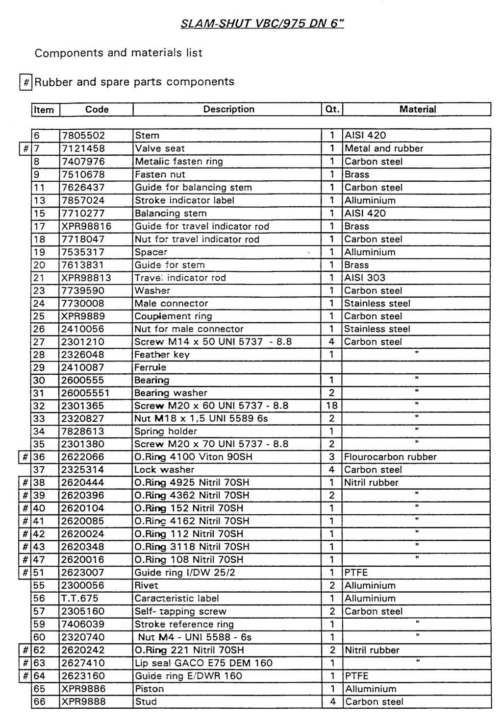
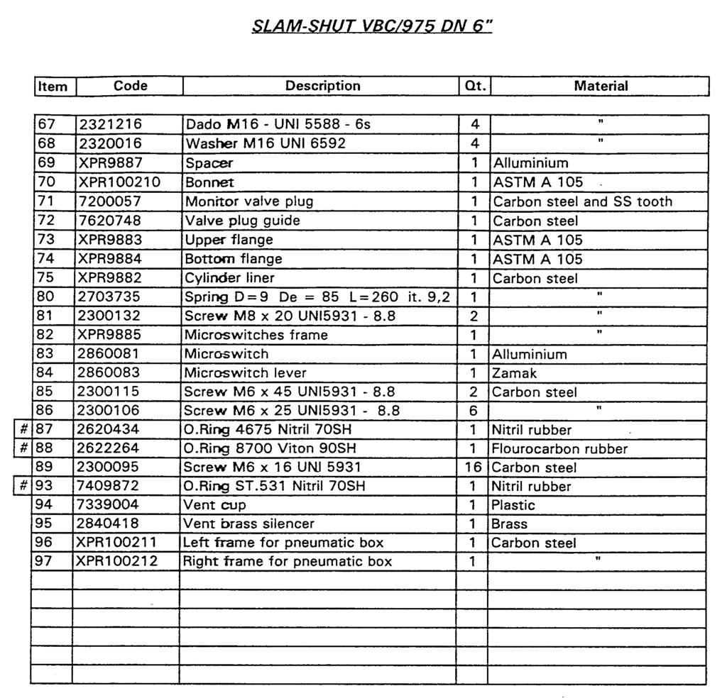
18 6. MAINTENANCE 6.1 General Before any maintenance operation, discharge the pressure as follows: a) close the upstream on/off valve V1 b) close the downstream on/off valve V2 c) check that the cut-off device is open d) very slowly discharge the pressure through the bleed cock to the atmosphere (6) In the event of intervention for minimum pressure, discharge the pressure upstream from the valve by turning the 3-way cock (1) to the bypass position. 6.2 Disassembly Before starting the disassembly operations, it is necessary to check that: - the valve has been cut off upstream and downstream and that the pressure between the two on-off valves has been discharged - you have a set of spanners as specified in the table - you have the recommended set of spare parts Depending on the type of problem which has occurred, maintenance may involve: a) the on/off valve b) the single action pneumatic actuator c) the line-off device a) On-off valve It is possible to remove the cut-off device valve without disconnecting the body from the piping. - disconnect all the feed and sensing line connections, by unscrewing all the conical seal connections - slacken the fixing screw of the LINE OFF system support bracket - slacken the fixing screw pos. (32) and remove the cut-off device device - slacken the nuts pos. (33) fixing the obturator pos. (71) to the rod pos.(6) - remove the obturator pos.(71) - relaxe completely the spring pos. (80) unscrewing the locknut pos.(9) - remove the spring pos.(80) - slacken the fixing screws pos. (86) and remove the obturator guide pos.(72) - slacken the fixing screws pos. (89) of the lock ring pos. (8) of the reinforced gasket 16
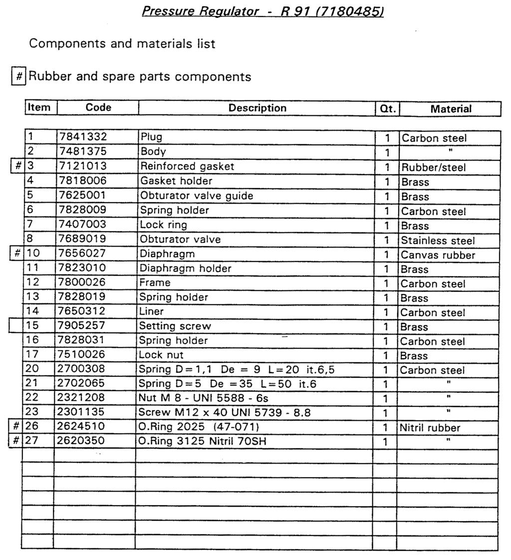
19 pos.(7) - remove the lock ring pos. (8) and the reinforced gasket pos.(7) - control and clean the metal parts - carefully control the state of the obturator valve seat - replace all the components in the spare parts kit Single action pneumatic actuator - unscrew the nut pos. (60) and remove the stroke reference ring pos. (59) - slacken the fixing nuts pos. (67) and remove the flange pos. (74)and the plating pos.(75) - remove the balancing piston pos.(15) - keeping the spacer pos. (69) firm, unscrew and remove the balancing rod guide pos. (11) remove the piston pos. (65) and the spacers pos. (69) and (19) - slacken the fixing screws pos.(27) - separate the flange pos. (73) from the cover pos. (70) - remove the rod guide pos. (20) from the cover pos. (70) - replace all the components in the spare parts kit b) Line-off device Filter - -slacken the cup pos. (1) and remove from cover pos. (2) - slacken the screw pos. (5)and remove the filter cartridge pos.(4) - replace all the components in the spare parts kit R91 pressure regulator - slacken the locknut pos.(17) - turn the adjusting screw pos. (15) anticlockwise to slacken to the end of its stroke - slacken the screws pos. (23) and remove the sleeve pos.(14), the spring support pos.(16), the spring pos. (21) and the diaphragm holder assembly - unscrew the locknut pos. (22) from the diaphragm support pos. (11) and remove the spring support pos. (13) and the diaphragm pos.(10) - unscrew the plug pos. (1) and remove the spring support pos.(6), the spring pos.(20), the lock ring pos.(7), the obturator pos. (8) and the reinforced gasket pos.(3) 17
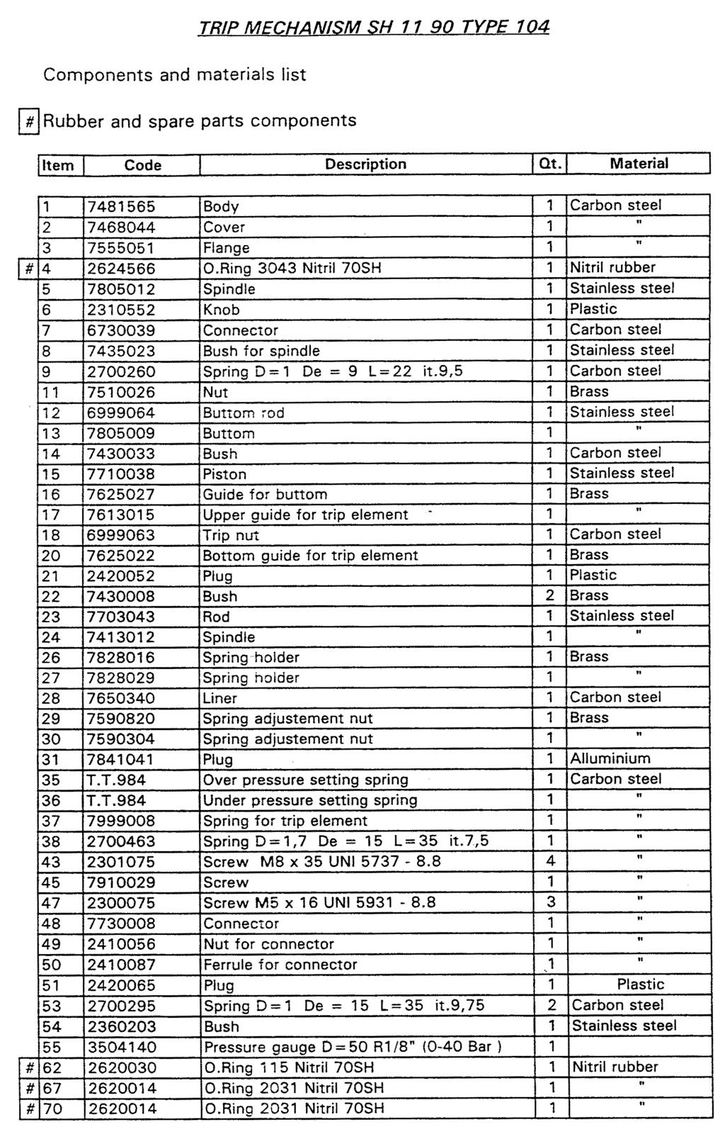
20 - replace all the components in the spare parts kit VS/FI bleed valve - unscrew the plug pos.(3), discharge the spring pos. (4) and remove the obturator pos.(2) - carefully check the state of the valve seat - replace all the components in the spare parts kit Pressure switch device type SH1190 type disconnect the signal take-off - slacken the fixing screws pos. (43) - remove the cover pos. (2) - replace all the components in the spare parts kit NOTE: After cut-off device intervention, close the on/off valves upstream and downstream and discharge the pressure. The cut-off device must never be actuated before remedying the problem that caused it to trip. 18
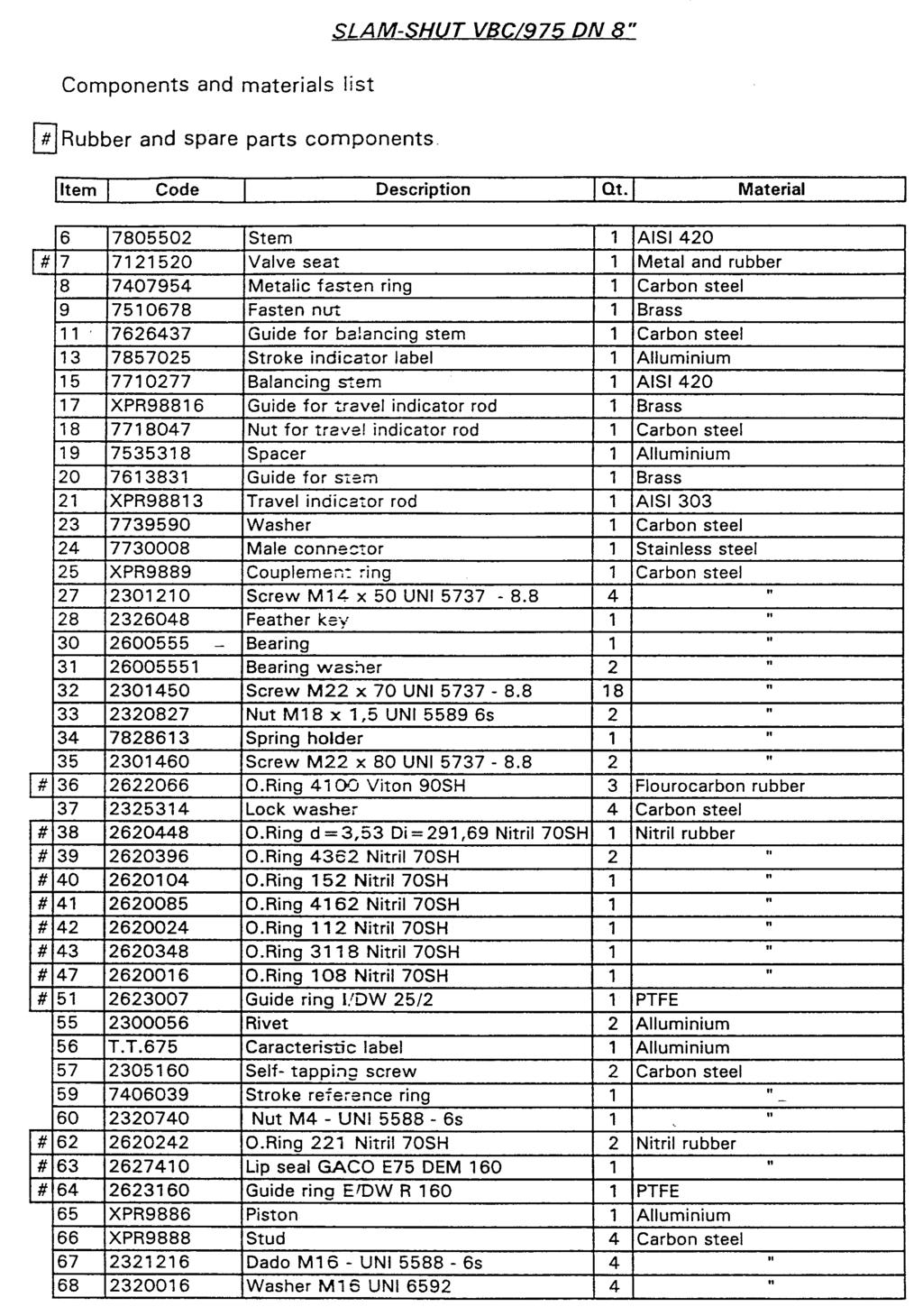
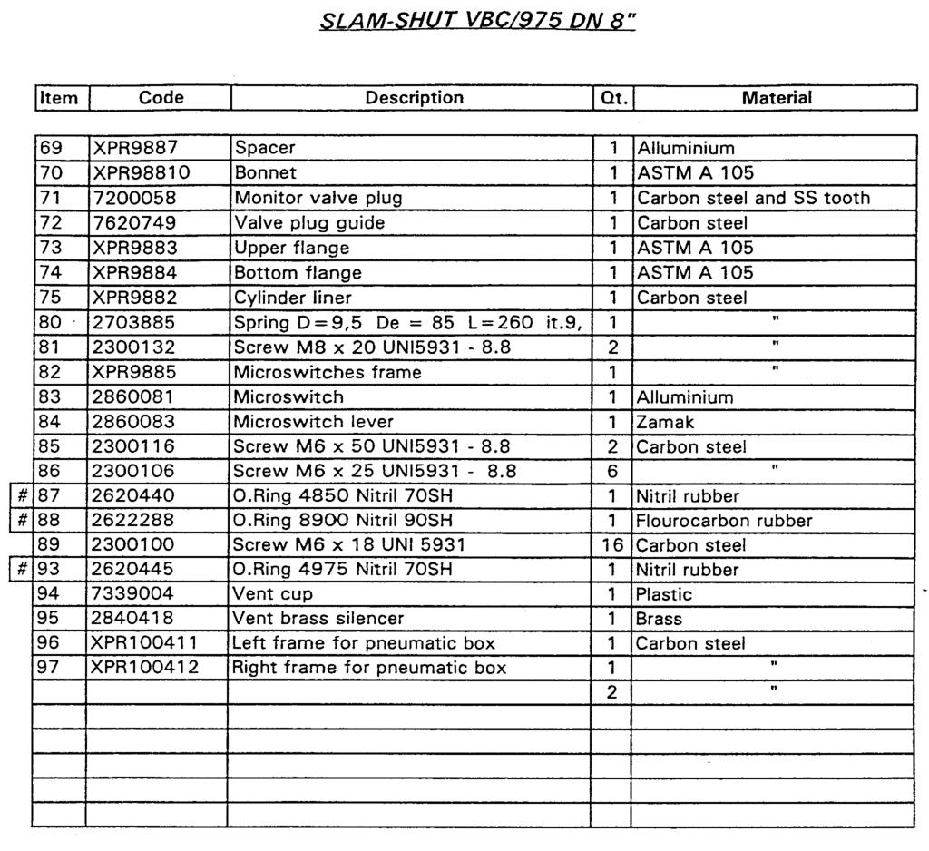
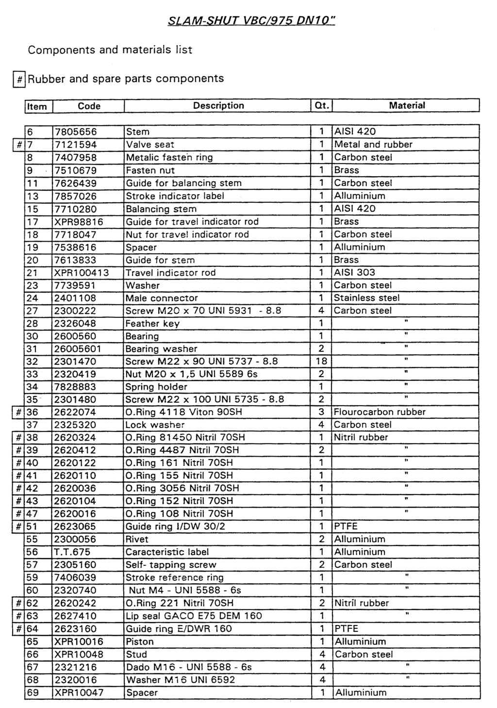
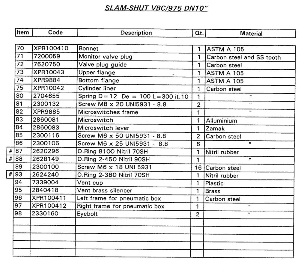
21 7. COMPONENTS AND SPARE PARTS LIST 19
22 20
23 21
24 22
25 23
26 24
27 25
28 26
29 27
30 28
31 29
32 30
33 31
34 32
35 33
36 34
37 I dati sono indicativi e non impegnativi. Ci riserviamo di apportare eventuali modifiche senza preavviso. The data are not binding. We reserve the right to make modifications without prior notice. Pietro Fiorentini S.p.A. UFFICI COMMERCIALI: OFFICES: I MILANO Italy - Via Rosellini, 1 - Phone (10 linee a.r.) - Telefax sales@fiorentini.com I ARCUGNANO (VI) Italy - Via E. Fermi, 8/10 - Phone (10 linee a.r.) - Telefax arcugnano@fiorentini.com I NAPOLI Centro direzionale - Isola G 1 Phone Telefax napoli@fiorentini.com ASSISTENZA POST-VENDITA E SERVIZIO RICAMBI: SPARE PARTS AND AFTER-SALES SERVICE: I ARCUGNANO (VI) - Italy - Via E. Fermi, 8/10 - Phone (10 linee a.r.) - Telefax service@fiorentini.com
MANUALLY OPERATED VALVE VLM SYNCROFLUX TECHNICAL MANUAL MT042/E
 MANUALLY OPERATED VALVE VLM SYNCROFLUX TECHNICAL MANUAL MT042/E INSTALLATION, COMMISSIONING AND MAINTENANCE INSTRUCTIONS CONTENTS 1.0 INTRODUCTION 1.1 MAIN CHARACTERISTICS 1.2 VALVE CONTROL 2.0 INSTALLATION
INSTRUCTIONS FOR THE INSTALLATION, COMMISSIONING AND MAINTENANCE
 BALL VALVE FULLY WELDED TECHNICAL MANUAL INSTRUCTIONS FOR THE INSTALLATION, COMMISSIONING AND MAINTENANCE MT 040/E 1 Edition 01/10/15 rev.02 TABLE OF CONTENTS 1.0 INTRODUCTION 1.1 MAIN SPECIFICATIONS 1.2
MT-239-E ENGLISH PRESSURE REGULATOR STAFLUX MINI TECHNICAL MANUAL INSTALLATION, COMMISSIONING AND MAINTENANCE INSTRUCTIONS
 MT-239-E ENGLISH PRESSURE REGULATOR STAFLUX MINI TECHNICAL MANUAL INSTALLATION, COMMISSIONING AND MAINTENANCE INSTRUCTIONS Technical manual MT 239-E 1 STAFLUX MINI Technical manual MT 239-E 2 Technical
CARTRIDGE FILTERS TECHNICAL MANUAL MT 080. Installation, commissioning and maintenance instructions. 08/02 Edition
 CARTRIDGE FILTERS TECHNICAL MANUAL MT 080 Installation, commissioning and maintenance instructions 08/02 Edition 1 2 CONTENTS 1.0 PAGE INTRODUCTION 1.1 MAIN FEATURES 1.2 OPERATION 1.3 CLOSING OF HEAD WITH
PRESSURE REGULATOR NORVAL TECHNICAL MANUAL MT044
 E PRESSURE REGULATOR NORVAL TECHNICAL MANUAL MT044 INSTALLATION, COMMISSIONING AND MAINTENANCE INSTRUCTIONS www.mvandc.com NORVAL Inlet pressure. Outlet pressure. Issue February 2003 2 DECLARATION OF CONFORMITY
PRESSURE REGULATOR APERFLUX 851 TECHNICAL MANUAL MT049
 E PRESSURE REGULATOR APERFLUX 851 TECHNICAL MANUAL MT049 INSTALLATION, COMMISSIONING AND MAINTENANCE INSTRUCTIONS www.mvandc.com AR 73 MAX 80 1 2 3 4 5 6 7 7 6 5 4 3 2 1 M I N 304/A INLET PRESSURE CONTROL
Aperflux TECHNICAL MANUAL PRESSURE REGULATOR ENGLISH MT-208-E INSTALLATION, COMMISSIONING AND MAINTENANCE INSTRUCTIONS
 MT-208-E ENGLISH PRESSURE REGULATOR Aperflux TECHNICAL MANUAL INSTALLATION, COMMISSIONING AND MAINTENANCE INSTRUCTIONS 1 Pressure Regulator INLET PRESSURE OUTLET PRESSURE CONTROL PRESSURE PRECAUTION GENERAL
MT-208-E ENGLISH PRESSURE REGULATOR. Aperflux TECHNICAL MANUAL INSTALLATION, COMMISSIONING AND MAINTENANCE INSTRUCTIONS
 MT-208-E ENGLISH PRESSURE REGULATOR Aperflux TECHNICAL MANUAL INSTALLATION, COMMISSIONING AND MAINTENANCE INSTRUCTIONS Technical manual MT 208-E 1 Pressure Regulator INLET PRESSURE OUTLET PRESSURE CONTROL
MT-182-E ENGLISH PRESSURE REGULATOR. Aperval TECHNICAL MANUAL INSTALLATION, COMMISSIONING AND MAINTENANCE INSTRUCTIONS
 MT-182-E ENGLISH PRESSURE REGULATOR Aperval TECHNICAL MANUAL INSTALLATION, COMMISSIONING AND MAINTENANCE INSTRUCTIONS Technical Manual MT 182-E 1 Pressure Regulator INLET PRESSURE OUTLET PRESSURE CONTROL
Manual Actuated Boiler Blowdown Valves
 Manual Actuated Boiler Blowdown Valves Installation and Maintenance Instructions 1. Safety information 2. General product information 3. Installation 4. Operation 5. Maintenance 6. Spare parts p.1 1. Safety
PRESSURE REGULATOR DIVAL DIVAL DIVAL TECHNICAL MANUAL MT036 INSTALLATION, COMMISSIONING AND MAINTENANCE INSTRUCTIONS
 E PRESSURE REGULATOR DIVAL DIVAL 160-250 DIVAL 50-75 - 100-125 TECHNICAL MANUAL MT036 INSTALLATION, COMMISSIONING AND MAINTENANCE INSTRUCTIONS DIVAL 160-250 INLET PRESSURE 50-75 - 100-125 OUTLET PRESSURE
RCV-125 REMOTE CONTROL SYSTEM IMPORTANT WARNING FOR SAFER BLAST CLEANING
 OWNER S MANUAL RCV-125 REMOTE CONTROL SYSTEM IMPORTANT WARNING FOR SAFER BLAST CLEANING 1. Use protective equipment: Abrasive-resistant clothing, safety shoes, leather gloves, ear protection, CE-approved
OPERATING INSTRUCTIONS
 0/05 OPERATING INSTRUCTIONS for gas pressure regulators PN0 with integrated slam shut valve (SSV) and integrated limited capacity safety relief valve (RV) MR 25 F0, MR 25 SF0 p e 20 kpa - 0 MPa (0,2-0
INSTALLATION INSTRUCTIONS. CVS 67CFR Pressure Reducing Instrument Supply Regulator INTRODUCTION
 INSTALLATION INSTRUCTIONS CVS 67CFR Pressure Reducing Instrument Supply Regulator INTRODUCTION The CVS Controls 67CFR Filter regulator is a pressure reducing supply regulator typically used for pneumatic
Differential Pressure Regulator Type Type 45-6 (0.1 to 1 bar, DN 15) Mounting and Operating Instructions EB 3226 EN
 Mounting and Operating Instructions EB 3226 EN") Differential Pressure Regulator Type 45-6 Type 45-6 (0.1 to 1 bar, DN 15) Mounting and Operating Instructions EB 3226 EN Edition March 2008 Contents Contents Page 1 Design and principle of operation...................
Differential Pressure Regulator Type 45-6 Type 45-6 (0.1 to 1 bar, DN 15) Mounting and Operating Instructions EB 3226 EN Edition March 2008 Contents Contents Page 1 Design and principle of operation...................
Pressure Regulators. Aperflux 101
 Pressure Regulators Aperflux 101 Aperflux 101 > Pressure regulators Top Easy Maintenance Integral Silencing Cage High Accuracy Dinamically Balanced Pilot Installation On Any Position Introduction Aperflux
Slam Shut Valves SBC 782
 Slam Shut Valves SBC 782 SBC 782 > Slam shut valves Introduction SBC 782 is a compact safety device (SAV) which quickly intercepts gas flow whenever the pressure under monitoring reaches preset limits,
Installation and operating manual. Pneumatic control station LK product no: PCS 1-10
 LK product no: PCS 1-10 Article no: 74503 Revision:8 Article no: 74503 Revision: 8 2 (23) Contents 1. General information... 5 2. Safety precautions... 5 2.1 Significance of symbols... 5 2.2 Explanatory
Installation, Operation and Maintenance Manual for Back Pressure Regulator
 Installation, Operation and Maintenance Manual for Back Pressure Regulator Model 8860 2009 Groth Corporation IOM-8860 Rev. B 12541 Ref. ID: 95565 Page 2 of 13 Table of Contents I. INTRODUCTION 3 II. DESIGN
Aperval Pressure Regulators
 Pressure Regulators Pressure regulators is pilot-controlled pressure regulator for medium and low pressure applications. is normally a fail to open regulator and specificaly will open under the following
THE BP-301 SERIES. Operating and Service Manual. Series includes all variants of BP-301 (LF 0.1Cv / MF 0.5Cv)
") THE BP-301 SERIES Operating and Service Manual Series includes all variants of BP-301 (LF 0.1Cv / MF 0.5Cv) Issue B October 2015 1 TABLE OF CONTENTS 1. Description... 3 2. Installation... 3 3. Operation...
THE BP-301 SERIES Operating and Service Manual Series includes all variants of BP-301 (LF 0.1Cv / MF 0.5Cv) Issue B October 2015 1 TABLE OF CONTENTS 1. Description... 3 2. Installation... 3 3. Operation...
THE HF-300 SERIES. Operating and Service Manual. Series includes all variants of HF-300/301
 THE HF-300 SERIES Operating and Service Manual Series includes all variants of HF-300/301 Issue A July 2015 1 TABLE OF CONTENTS 1. Description... 3 2. Installation... 3 3. Operation... 4 3.1. Spring Loaded...
MEGR-1627 Instruction Manual
 MEGR-1627 HIGH FLOW GAS REGULATOR Instruction Manual- Look Inside For: Description Installation Remote Vent Line Installations Startup and Adjustment Shutdown Maintenance Body Maintenance Procedures Diaphragm
Pressure Reducing Valve for Steam Type 2333 A
 Pressure Reducing Valve for Steam Type 2333 A Fig. 1 Type 2333 A 1. Design and principle of operation The pressure reducing valve consists of a balanced control valve and a closing actuator equipped with
Pressure Regulators DIVAL TECHNICAL MANUAL
 Pressure Regulators DIVAL 507-512 TECHNICAL MANUAL DIVAL 507-512 DIVAL: Basic version INLET PRESSURE OUTLET PRESSURE 2 MT 236 ed.2015 (Rev.B) GERAL WARNINGS The equipment described in this manual is a
VRPP 170 Pressure regulating valve by pneumatic control
 Last update: 02/11/2011 VRPP 170 Pressure regulating valve by pneumatic control Pressure regulating valve. At gun shut off, the water flow is bypassed at reduced pressure. Technical manual: E 246 DN 25
PULSAR4 Pressure regulating valve (Unloader)
") Ultimo aggiornamento: 15/12/11 PULSAR4 Pressure regulating valve (Unloader) At gun closure, the waterflow is discharged in bypass reducing the pressure in the system upstream of the valve. Technical manual:
Ultimo aggiornamento: 15/12/11 PULSAR4 Pressure regulating valve (Unloader) At gun closure, the waterflow is discharged in bypass reducing the pressure in the system upstream of the valve. Technical manual:
PULSAR4 Pressure regulating valve (Unloader)
") Ultimo aggiornamento: 20/04/18 PULSAR4 Pressure regulating valve (Unloader) At gun closure, the waterflow is discharged in bypass reducing the pressure in the system upstream of the valve. Technical manual:
Ultimo aggiornamento: 20/04/18 PULSAR4 Pressure regulating valve (Unloader) At gun closure, the waterflow is discharged in bypass reducing the pressure in the system upstream of the valve. Technical manual:
TECHNICAL DATA. Page 1 of 12
 Page 1 of 12 1. DESCRIPTION The Viking Regulating Valve is a direct-acting, single-seated, spring-loaded diaphragm valve. When installed as a pilot regulating valve on a Viking Model H or J Flow Control
LRS(H)4 Pressure-Reducing Regulator User Manual
4 Pressure-Reducing Regulator User Manual") LRS(H)4 Pressure-Reducing Regulator User Manual Read the complete manual before installing and using the regulator. 2 Safe Product Selection When selecting a product, the total system design must be considered
LRS(H)4 Pressure-Reducing Regulator User Manual Read the complete manual before installing and using the regulator. 2 Safe Product Selection When selecting a product, the total system design must be considered
Pressure regulators. Introduction. TR Head. 3 ways body Dival
 Pressure Regulators > Pressure regulators Introduction series pressure regulators are direct acting devices for low and medium pressure applications controlled by a diaphragm and counter spring. These
299H Series. Introduction. P.E.D. Categories. Specifications. Installation. Warning. Installation Guide English September 2012
 Installation Guide English September 2012 299H Series Introduction This Installation Guide provides instructions for installation, startup, and adjustment of 299H Series regulators. To receive a copy of
INSTRUCTION MANUAL COMPACT PRESS. SWITCHES SERIES PCS & PCA
 COMPACT PRESS. SWITCHES SERIES PCS & PCA WEATHERPROOF SERIES PCS SERIES PCA EXPLOSIONPROOF B B A A B = Cable entry A = Pressure connection WEIGHT 1kg dimensions in mm B = Cable entry A = Pressure connection
VRPP 200/280 Pressure regulating valve by pneumatic control
 Ultimo aggiornamento: 20/04/18 VRPP 200/280 Pressure regulating valve by pneumatic control Technical manual: E 270 The Valve, fed by compressed air, maintains the pressure steady throughout the circuit
KTM OM-2 SPLIT BODY FLOATING BALL VALVES INSTALLATION AND MAINTENANCE INSTRUCTIONS
 Before installation these instructions must be fully read and understood SECTION 1 - STORAGE 1.1 Preparation and preservation for storage All valves should be properly packed in order to protect the parts
MODEL 200 KNIFE GATE VALVES INSTALLATION & MAINTENANCE MANUAL
 MODEL 200 KNIFE GATE VALVES INSTALLATION & MAINTENANCE MANUAL Index 1. List of components / General arrangement 2. Description 3. Handling 4. Installation 5. Actuators / Operation 6. Maintenance a. Changing
VB85/ Pressure regulating valve (Unloader)
") Ultimo aggiornamento: 20/09/12 VB85/160 280 Pressure regulating valve (Unloader) At gun closure, the waterflow is discharged in bypass reducing the pressure in the system upstream of the valve. Technical
Ultimo aggiornamento: 20/09/12 VB85/160 280 Pressure regulating valve (Unloader) At gun closure, the waterflow is discharged in bypass reducing the pressure in the system upstream of the valve. Technical
Slam Shut Valves SCN
 Slam Shut Valves SCN SCN > Slam shut valves Introduction SCN is a compact safety device (SAV) which quickly intercept gas flow whenever the pressure under monitoring reaches a pre-set limits, or whenever
Mounting and operating instructions EB 2530 EN. Self-operated Pressure Regulator. Pressure Reducing Valve Type M 44-2
 Self-operated Pressure Regulator Pressure Reducing Valve Type M 44-2 Type M 44-2, connection G 1 4, K VS = 0.15 Type M 44-2, connection G 1, K VS = 6 Fig. 1 Type M 44-2 Pressure Reducing Valve Mounting
TECHNICAL DATA. Pressure Regulation 531a. April 24, 2009
 April 24, 29 Pressure Regulation 531a 1. DESCRIPTION The Viking Regulating Valve is a direct-acting, single-seated, spring-loaded diaphragm valve. When installed as a pilot regulating valve on a Viking
Operating Manual. R280 Pressure regulator made of brass. 1. Intended Use
 Pressure regulator made of brass Operating Manual 1. Intended Use Line or outlet pressure regulators- /reducer for Air, gases and liquids which is designed to effect reduction to a downstream pressure
Norval Pressure Regulators
 Pressure Regulators Pressure regulators NORVAL pressure regulators are balanced direct acting devices for low and medium pressure applications controlled by a diaphragm and counter spring. These regulators
Un-Pressurized Orefice Fittings FIO EZ. Parts List and Operation Instructions TECHNICAL MANUAL. Dn 2-6 Class Lbs
 Un-Pressurized Orefice Fittings FIO EZ Parts List and Operation Instructions TECHNICAL MANUAL Dn 2-6 Class 150-600 Lbs US US 2 FIO EZ - MT 108-US - 05-2016 FIO EZ Important Instructions US Pietro Fiorentini
Mounting and Operating Instructions EB 2558 EN. Self-operated Pressure Regulators. Type Pressure Build-up Regulator
 Self-operated Pressure Regulators Type 2357-31 Pressure Build-up Regulator with safety function and integrated excess pressure valve Type 2357-31 with non-return unit at port C Ports A and B with soldering
Installation Operation Maintenance. Bermad Level Control Valve with Modulating Horizontal Float Pilot valve One Way Flow IOM.
 Bermad Level Control Valve with Modulating Horizontal Float Pilot valve One Way Flow Model: FP 450-80 Installation Operation Maintenance PAGE 1 OF 5 1. Safety First BERMAD believes that the safety of personnel
Type 310A-32A Pressure Reducing Regulator and Type 310A-32A-32A Working Monitor Regulator
 Instruction Manual Form 5351 Type 310A March 2010 Type 310A-32A Pressure Reducing Regulator and Type 310A-32A-32A Working Monitor Regulator! Warning Failure to follow these instructions or to properly
64 Series Pressure Reducing Regulators
 Instruction Manual Form 1245 64 Series March 2006 64 Series Pressure Reducing Regulators W1943 Figure 1. 64 Series Regulator Introduction Scope of Manual This manual provides instructions for the installation,
Model: 43T. Bermad Pressure Relief Valve
 Model: 43T Bermad Pressure Relief Valve Installation Operation Maintenance Manual () Rev.C1_01.08.17 Page 1 of 10 Safety First BERMAD believes that the safety of personnel working with and around our equipment
Type 1367 High-Pressure Instrument Supply System with Overpressure Protection
 Instruction Manual D100343X012 Type 1367 November 2017 Type 1367 High-Pressure Instrument Supply System with Overpressure Protection TYPE 252 FILTER 2ND-STAGE TYPE 67CF FILTER-STYLE REGULATOR INLET TYPE
Installation, Maintenance and Operation Manual Pressure Regulator Valve Model DOMUS
 Installation, Maintenance and Operation Manual Pressure Regulator Valve Model DOMUS INDEX 1.0 - GENERAL ADVERTSIMENT... 3 1.1 INSTRUCTIONS PRIOR COMMISSIONING... 3 1.2 HEALTH AND SAFETY... 3 1.2.1 NOISE...
FTGS14 Ball Float Steam Trap DN15 (½") to DN25 (1")
 to DN25 (1)") 1458050/5 IM-P145-12 ST Issue 5 FTGS14 Ball Float Steam Trap DN15 (½") to DN25 (1") Installation and Maintenance Instructions 1. Safety information 2. General product information 3. Installation 4. Commissioning
1458050/5 IM-P145-12 ST Issue 5 FTGS14 Ball Float Steam Trap DN15 (½") to DN25 (1") Installation and Maintenance Instructions 1. Safety information 2. General product information 3. Installation 4. Commissioning
WW-720. Pressure Reducing Control Valve
 WW-720 Pressure Reducing Control Valve (Size Ranges: 2-4 and 6-14 ) Installation Operation & Maintenance Page 1 of 6 1. DESCRIPTION The Model 720 Pressure Reducing is an automatic control valve (powered
WW-720. Pressure Reducing Control Valve
 WW-720 Pressure Reducing Control Valve (Size Ranges: 2-4 and 6-14 ) Installation Operation & Maintenance Page 1 of 6 1. DESCRIPTION The Model 720 Pressure Reducing is an automatic control valve (powered
RS(H)10,15 USER MANUAL. Read the complete manual before installing and using the regulator.
10,15 USER MANUAL. Read the complete manual before installing and using the regulator.") RS(H)10,15 USER MANUAL Read the complete manual before installing and using the regulator. WARNING INCORRECT OR IMPROPER USE OF THIS PRODUCT CAN CAUSE SERIOUS PERSONAL INJURY AND PROPERTY DAMAGE. Due to
RS(H)10,15 USER MANUAL Read the complete manual before installing and using the regulator. WARNING INCORRECT OR IMPROPER USE OF THIS PRODUCT CAN CAUSE SERIOUS PERSONAL INJURY AND PROPERTY DAMAGE. Due to
BCV31 DN40 - Blowdown Control Valve
 4034850/5 IM-P403-71 AB Issue 5 BCV31 DN40 - Blowdown Control Valve Installation and Maintenance Instructions 1. Safety information 2. Application 3. Technical data 4. Operation 5. Installation 6. Flow
Mounting and Operating Instructions EB 3007 EN. Self-operated Pressure Regulators. Differential Pressure Regulators (opening) Type Type 42-25
 Type Type 42-25") Self-operated Pressure Regulators Differential Pressure Regulators (opening) Type 42-20 Type 42-25 Type 42-20 Differential Pressure Regulator Type 42-25 Differential Pressure Regulator Mounting and Operating
Self-operated Pressure Regulators Differential Pressure Regulators (opening) Type 42-20 Type 42-25 Type 42-20 Differential Pressure Regulator Type 42-25 Differential Pressure Regulator Mounting and Operating
RD(H)20/25 Pressure-Reducing Regulator User Manual
20/25 Pressure-Reducing Regulator User Manual") RD(H)20/25 Pressure-Reducing Regulator User Manual Read the complete manual before installing and using the regulator. 2 Safe Product Selection When selecting a product, the total system design must be
RD(H)20/25 Pressure-Reducing Regulator User Manual Read the complete manual before installing and using the regulator. 2 Safe Product Selection When selecting a product, the total system design must be
Bermad Pressure Reducing. Model: 42T
 Bermad Pressure Reducing Pilot Operated Pressure Control Valve Model: 42T Installation Operation Maintenance Manual (IOM) REV. 27.7.17 Page 1 of 12 Safety First BERMAD believes that the safety of personnel
FILTER REGULATORS MODEL NO: CAT155 & CAT156 FITTING & MAINTENANCE INSTRUCTIONS PART NO: & ORIGINAL INSTRUCTIONS
 FILTER REGULATORS MODEL NO: CAT155 & CAT156 PART NO: 3120169 & 3120170 FITTING & MAINTENANCE INSTRUCTIONS ORIGINAL INSTRUCTIONS GC0117 INTRODUCTION Thank you for purchasing this CLARKE Filter/Regulator.
TESCOM 50-4X Series Safety, Installation & Start-Up Procedures
 Operations & Service Manual TESCOM 50-4X Series Safety, Installation & Start-Up Procedures Do not attempt to select, install, use or maintain this product until you have read and fully understood this
TECHNICAL DATA. the Viking Pilot Pressure Regulating Valve 1 Model A-1 Speed Control Assembly: OBSOLETE. the Viking Speed Control Assembly 1
 November 30, 1994 534 a 1. PRODUCT NAME VIKING 2" (50mm), 3" (75mm), 4" (100mm), 6" (150mm) 2. MANUFACTURER THE VIKING CORPORATION 210 N. Industrial Park Road Hastings, Michigan 49058 U.S.A. Telephone:
TECHNICAL DATA. Q = C v P S
 Page 1 of 13 1. DESCRIPTION The Viking 6 Model G-6000 Dry Valve Riser Assembly consists of a small profile, light weight, pilot operated valve that is used to separate the water supply from the dry sprinkler
Operation & Maintenance Manual Place this manual with valve or person responsible for maintenance of the valve
 Operation & Maintenance Manual Place this manual with valve or person responsible for maintenance of the valve Model CYCLE GARD II, CI & CNA YOUR PRODUCT INFORMATION: Model Number: Date: Serial Number:
English. Introduction. Safety Instructions. All Products. Inspection and Maintenance Schedules. Parts Ordering. Specifications WARNING WARNING
 Contents All Products... Gb-1 Control Valves... Gb-2 Control Valve Actuators... Gb-3 Regulators... Gb-3 Relief Valves... Gb-4 Instruments, Switches, and Accessories... Gb-4 Products Covered by Battery
BSA6T and BSA64T Stainless Steel Bellows Sealed Stop Valves Installation and Maintenance Instructions
 1843950/3 IM-P184-03 ST Issue 3 BSA6T and BSA64T Stainless Steel Bellows Sealed Stop Valves Installation and Maintenance Instructions 1. General safety information 2. General product information 3. Installation
KTM 50 (DN ) Installation, maintenance and operating instructions
 Installation, maintenance and operating instructions") 52 762-306 09.2014 KTM 50 (DN 100-200) Installation, maintenance and operating instructions General High-performing and compact, these pressure-independent control valves for variable flow heating and
52 762-306 09.2014 KTM 50 (DN 100-200) Installation, maintenance and operating instructions General High-performing and compact, these pressure-independent control valves for variable flow heating and
Operating and maintenance manual Filter and reducing station Series / 1.0
 Operating and maintenance manual Filter and reducing station Series 961 04.2017 / 1.0 Original instructions ARCA Regler GmbH. All rights reserved. Cover picture background: Freepik.com ARCA Regler GmbH
TECHNICAL DATA 3 MODEL G-3000 DRY VALVE RISER ASSEMBLY
 Page 1 of 13 1. DESCRIPTION The Viking 3 Model G-3000 Dry Valve Riser Assembly is equipped with a small profile, light weight, pilot operated valve that is used to separate the water supply from the dry
USM21 Sealed Bimetallic Steam Trap for use with Pipeline Connectors Installation and Maintenance Instructions
 6250250/1 IM-P625-03 ST Issue 1 USM21 Sealed Bimetallic Steam Trap for use with Pipeline Connectors Installation and Maintenance Instructions 1. General safety information 2. General product information
THE MF-400 SERIES. Operating and Service Manual. Series includes all variants of MF-400/401
 THE MF-400 SERIES Operating and Service Manual Series includes all variants of MF-400/401 Issue A October 2013 1 TABLE OF CONTENTS 1. Description... 3 2. Installation... 3 3. Operation... 4 4. Special
MAINTENANCE AND OPERATING MANUAL
 MAINTENANCE AND OPERATING MANUAL Cyclone condensate separator Type ASA EN EN Maintenance and operating manual Purpose and appropriate use Dear Customer, thank you for choosing our product. In order to
Float Operated Level Controllers
 CONTENTS Float Operated Level Controllers IM0015 Nov. 2014 PAGE Introduction 1 Scope 1 Description 1 Specification 1 Control Installation 2 INTRODUCTION Side Mount Back Mount Prior to installing, the instructions
1305 Series Pressure Reducing Regulators
 Instruction Manual Form 1095 1305 Series October 2009 1305 Series Pressure Reducing Regulators! Warning Fisher regulators must be installed, operated, and maintained in accordance with federal, state,
TECHNICAL DATA. Q= Cv S
 Page 1 of 13 1. DESCRIPTION The Viking 4 inch Model G-4000 Dry Valve Riser Assembly consists of a small profile, light weight, pilot operated valve that is used to separate the water supply from the dry
INSTALLATION OPERATION MAINTENANCE
 Bermad Electrically Controlled On-Off Deluge Valve Model: 400E-3D INSTALLATION OPERATION MAINTENANCE Application Engineering BERMAD 1. Safety First BERMAD believes that the safety of personnel working
Type ACE97. Introduction. Installation. P.E.D. Categories. Specifications. Overpressure Protection. Installation Guide English May 2002
 Installation Guide English May 2002 Type ACE97 Introduction This installation guide provides instructions for installation, startup, and adjustment. To receive a copy of the instruction manual, contact
SA121, SA122, SA123, SA128 and SA1219 Self-acting Temperature Control Systems (Dial Adjustment)
") 3820050/4 IM-P382-01 CH Issue 4 SA121, SA122, SA123, SA128 and SA1219 Self-acting Temperature Control Systems (Dial Adjustment) Installation and Maintenance Instructions 1. Safety information 2. Use 3.
3820050/4 IM-P382-01 CH Issue 4 SA121, SA122, SA123, SA128 and SA1219 Self-acting Temperature Control Systems (Dial Adjustment) Installation and Maintenance Instructions 1. Safety information 2. Use 3.
Product Manual. Description. Specifications. CVS Type 1301F and CVS Type 1301G Regulator. Introduction
 Product Manual CVS Type 1301F and CVS Type 1301G Regulator Introduction This CVS Controls product manual includes instructions for the installation, adjustment, maintenance and parts ordering of the CVS
SA121, SA122, SA123, SA128 and SA1219 Self-acting Temperature Control Systems (Knob Adjustment)
") 3810050/5 IM-P381-01 CH Issue 5 SA121, SA122, SA123, SA128 and SA1219 Self-acting Temperature Control Systems (Knob Adjustment) Installation and Maintenance Instructions 1. Safety information 2. Use 3.
3810050/5 IM-P381-01 CH Issue 5 SA121, SA122, SA123, SA128 and SA1219 Self-acting Temperature Control Systems (Knob Adjustment) Installation and Maintenance Instructions 1. Safety information 2. Use 3.
Dri-Line Mk2 Spirax-Monnier Compressed Air Drain Trap
 0509950/2 IM-P050-21 CH Issue 2 Dri-Line Mk2 Spirax-Monnier Compressed Air Drain Trap Installation and Maintenance Instructions 1. Safety information 2. General product information 3. Installation and
RHPS Series RD(H)F40 User Manual. Read the complete manual before installing and using the regulator.
F40 User Manual. Read the complete manual before installing and using the regulator.") RHPS Series RD(H)F40 User Manual Read the complete manual before installing and using the regulator. 2 WARNING Before removing a regulator from the system for service, you must depressurize system purge
RHPS Series RD(H)F40 User Manual Read the complete manual before installing and using the regulator. 2 WARNING Before removing a regulator from the system for service, you must depressurize system purge
Installation, Operating and Maintenance Manual Overflow Regulator Type 94/ 94 E
 Installation, Operating and Maintenance Manual Overflow Regulator Type 94/ 94 E Table of content 1. General information on installation, operating and maintenance instructions 1.1 Hazard notices 1.2 Qualified
OPERATING AND MAINTENANCE MANUAL
 Series 4300 Engineered Performance TABLE OF CONTENTS 0 INTRODUCTION 1 1 Scope 1 2 Description 1 3 Specifications 1 0 INSTALLATION 1 1 Mounting 1 2 Piping 1 1 Connecting Process Pressure 2 2 Vent Connections
Norval Pressure regulator
 Norval Pressure regulator NORVAL Classification and Field of Application The NORVAL is a downstream pressure regulator, self actuated, spring loaded for medium and low pressure applications. It is suitable
TECHNICAL DATA Q= C. Table 1 - Specifications
 September 25, 2013 Pressure Regulation 537a 1. Description The Model B-3 Pilot Operated Pressure Control Valve is a factory assembled unit. The unit consists of a Model J-2 Halar coated Flow Control Valve,
Instruction Manual. Alfa Laval SB Pressure Exhaust Valve ESE02965-EN Original manual
 Instruction Manual Alfa Laval SB Pressure Exhaust Valve ESE02965-EN1 2015-10 Original manual Table of contents The information herein is correct at the time of issue but may be subject to change without
Pneumatic proportional controller Types M Types FM Function tested for use of the float in Ex-zone 0
 Operating Manual LTIA5E Pneumatic proportional controller Types M Types FM Function tested for use of the float in Ex-zone 0 Contents 1. Safety Instructions 2. Conformity to standards 3. Technical data
PV4 and PV6 Piston Valves
 1181250/1 IM-P118-05 ST Issue 1 PV4 and PV6 Piston Valves Installation and Maintenance Instructions 1. Safety information 2. General product information 3. Installation 4. Commissioning 5. Operation 6.
IFTGS14 Ball Float Steam Trap ½" and ¾" with Integral Spiratec Sensor
 6150350/3 IM-P615-12 ST Issue 3 IFTGS14 Ball Float Steam Trap ½" and ¾" with Integral Spiratec Sensor Installation and Maintenance Instructions 1. Safety information 2. General product information 3. Installation
TECHNICAL DATA CAUTION
 Page 1 of 12 1. DESCRIPTION The Viking Model C-2 Pilot Pressure Regulating Valve is a direct-acting, single-seated, spring-loaded diaphragm valve. When installed as a pilot regulating valve on a Viking
Model Secure-Gard Pilot Operated Vent Valve SECTION II. Remove all packing material inside and outside of the valve prior to installation.
 INSTALLATION, OPERATION AND MAINTENANCE MANUAL (IOM) IOM - 1049 01-17 Model 1049 Secure-Gard Pilot Operated Vent Valve ISO Registered Company SECTION I I. DESCRIPTION AND SCOPE The Model 1049 Secure-Gard
Type S301 & S302 Gas Regulators INTRODUCTION INSTALLATION. Scope of Manual. Description. Specifications. Type S301 and S302. Instruction Manual
 Fisher Controls Instruction Manual Type S301 & S302 Gas Regulators October 1981 Form 5180 WARNING Fisher regulators must be installed, operated, and maintained in accordance with federal, state, and local
Code AWC20HP Air Compressor
 Code 951816 AWC20HP Air Compressor Index of Contents Index of Contents 02 Declaration of Conformity 02 What s Included 03 Safety Precautions 03 Specifications (AWC20HP Air Compressor) 04 Assembly Instructions
Type FEQ Slam-Shut Valve
 Instruction Manual Form 5865 Type FEQ December 2012 Type FEQ Slam-Shut Valve Contents Introduction...1 Principle of Operation...1 Specifications...2 Installation...2 Commissioning...7 Adjustment...9 Shutdown...10
RTG 25. Introduction
 Introduction RTG 25 pressure regulator is included within the direct acting and balanced valve regulator class. These regulators have a large range of applications both in industrial and domestic installations.
553 Series.
 38467.03 www.caleffi.com Pre-adjustable filling units Copyright 01 Caleffi 3 Series Function The automatic filling valve is a device consisting of a pressure reducing valve with compensating seat, visual
MUELLER. A Wall Type. Indicator Post. Reliable Connections. General Information 2. Technical Data/ Dimensions 3. Installation 4-5.
 Installation Instructions manual MUELLER table of contents PAGE A-20814 Wall Type General Information 2 Technical Data/ Dimensions Installation 4-5 Maintenance 6 Parts 7 Indicator Post! WARNING: 1. Read
Gas Pressure Regulator HON 200
 Product information serving the gas industry worldwide Applications, characteristics, technical data Application Gas supply to municipal, industrial and individual consumers Regulator for low-load rails
TECHNICAL DATA Q = C. v P S. 2 Model G-2000 Dry valve. Page 1 of 13
 Page 1 of 13 1. Description The Viking 2 Model G-2000 Dry Valve Riser Assembly consists of a small profile, light weight, pilot operated valve that is used to separate the water supply from the dry sprinkler
Pressure booster combination DPA-CRVZS. Operating instructions a [ ]
![Pressure booster combination DPA-CRVZS. Operating instructions a [ ]](/thumbs/88/116599651.jpg "Pressure booster combination DPA-CRVZS. Operating instructions a [ ]") Pressure booster combination en Operating instructions 8074546 2017-07a [8074548] Original instructions -EN Identification of hazards and instructions on how to prevent them: Danger Immediate dangers which
Pressure booster combination en Operating instructions 8074546 2017-07a [8074548] Original instructions -EN Identification of hazards and instructions on how to prevent them: Danger Immediate dangers which