GASGUARD VENT LINE3 Ammonia Sensor OPERATING & INSTALLATION MANUAL
|
|
|
- Donald McDowell
- 5 years ago
- Views:
Transcription


1 GASGUARD VENT LINE3 Ammonia Sensor OPERATING & INSTALLATION MANUAL

2 Operating and Installation Manual Warning Use this product only in the manner described in this manual. If the equipment is used in a manner not specified by Calibration Technologies, the protection provided by the equipment may be impaired. This equipment should be installed by qualified personnel. 2
3 Operating and Instruction Manual Table of Contents General description. 4 Installation. 4 Locating the sensor. 4 Installation guidelines 5 Wiring.. 6 Operation... 7 Start-up 7 Calibration.. 7 Maintenance.. 10 Troubleshooting. 11 Specifications. 11 Warranty.. 12 For technical support, contact: Calibration Technologies 920 N Trade Winds Pkwy Columbia, MO sales@ctiengineering.com 3
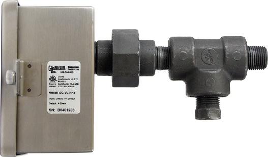
4 Operating and Installation Manual General Description The GG-VL2-NH3 sensor is a +24 VDC, three-wire, 4/20 ma sensor for ammonia. It provides an industry standard linear 4/20 ma output signal compatible with most gas detection systems and PLCs. The GG-VL2-NH3 provides real-time continuous monitoring of ammonia vapors in refrigeration system vent lines. Utilizing a long-life ammonia selective catalytic bead sensor, the GG-VL2-NH3 sensor can withstand occasional exposures to high concentrations of ammonia without shortening the life of the sensor. The sensor element can be accessed from inside of the stainless steel enclosure, and is sealed from the vent line to prevent ammonia from entering the enclosure. The transmitter circuit board is sealed in potting compound, protecting sensitive electronic components and copper tracing from corrosion. Recommended alarm setpoints for ammonia system vent lines are typically 0.5% to 1.0% NH3 (12 to 20 ma). Installation Locating the sensor Note: The ½ nipple of the supplied mounting kit should be welded to the relief header to allow airflow to the sensor. Note: Removing the ½ plug from the mounting kit usually allows more fresh air to the sensor and prevents signal rise over time. Since fresh air promotes longer sensor life and overall long-term sensor performance, it is recommended that the sensor is installed outdoors. Discharging to Atmosphere The GasGuard VL-NH3 sensor assembly should be installed outdoors three to five feet above the roofline, where the relief header discharges to the atmosphere (see Figure 1). Discharging to Diffusion Tank The GasGuard VL-NH3 sensor assembly should be installed on the atmospheric vent on top of the water tank (see Figure 2). This type of installation will not catch the weeping relief valves, but will detect ammonia vapors from the water during a release event. Caution: Installation of the sensor between SRV s and the diffusion tank will not allow fresh air in, so any introduction of ammonia gas will stay trapped in the header, resulting in a continuously high signal. A compressed air purge may be required for this. Contact Calibration Technologies for details. 4
5 Operating and Instruction Manual Union Nipple Relief header Mount sensor opposite side of discharge Installation Guidelines: Always assume system could discharge at any moment. Stay clear of discharge path and have escape route planned. Make sure ammonia does not discharge onto sensor assembly or personnel working on sensor (i.e. mount sensor opposite side of discharge). Install sensor enclosure with conduit hole facing down. Relief header Atmospheric vent ½ plug Sensor cable 3 5 Water tank Roofline Figure 1: Discharge to Atmosphere Figure 2: Discharge to Diffusion Tank 5
6 Operating and Installation Manual Wiring Electrical wiring must comply with all applicable codes. Electrical Power: 24 VDC regulated, 80 ma. Output: Linear 4/20 ma output. Monitoring equipment may have a maximum input impedance of 700 ohms. Cable Recommendation: 20/3 shielded cable (General Cable C2525A or equivalent). Length of cable to sensor should be no greater than 1,500 feet. Monitoring: Monitoring equipment must be configured to indicate a fault if the signal is below 1 ma. All signals over 20 ma must be considered high gas concentrations. Wiring Guidelines: Use only the existing conduit hole for connections to the sensor. Always use three-conductor, insulated, stranded, shielded copper cable. Do not pull sensor wiring with AC power cables. This can cause electrical interference. If cable runs cannot be made without a splice, all splice connections should be soldered. Ground the shield at the main control panel. Connect the shield wire in the sensor terminal block labeled SHLD. Always disconnect power at the controller before performing any wiring at the sensor. to case ground of monitoring equipment to Ground terminal of power supply to +24Vdc terminal of power supply to signal input of monitoring equipment Figure 3: Wiring diagram 6
7 Operating and Instruction Manual Operation Start-up Before applying power, make a final check of all wiring for continuity, shorts, grounds, etc. It is usually best to disconnect external alarms and other equipment from the sensor until the initial start-up procedures are completed. Recommended sensor stabilization time is 1 hour before making zero or span adjustments to ensure a solid 4mA zero-signal and optimal span accuracy. Span adjust can be made after 5 minutes but may result in 10% full-scale accuracy error. Sensor can be response tested immediately after power up. Note: Do not response test with propane or MAPP gas, as these can shorten sensor life. Response Test: 1. One person exposes each sensor to 1% or 2% NH3 calibration gas. 2. The second person stays at the control panel to determine that each sensor, when exposed to the gas, is connected to the proper input and responds, causing appropriate alarm functions. The GG-VL2-NH3 is designed with a unique safety signal latching feature. When the signal reaches 1% NH3, the signal latches until the concentration drops down below approx 4,000 ppm NH3. This prevents the possibility of a low reading when the gas concentration exceeds the Upper Explosion Limit. Calibration The GG-VL2-NH3 sensor comes factory calibrated and should require only minimal adjustments after installation. Calibration should be performed every six months. There are two pots on the preamp that are used for calibration (see Figure 4). Note: Never measure sensor output in ma. Always use mvdc or VDC voltmeter settings. Calibration Mode: Cal mode is required for calibrating the sensor. It clears the averaging, latching and deadband (factory set to 8 ma). Pressing the CAL switch enables cal mode and the green LED will flash. To exit out of cal mode, press the CAL switch or after 6 minutes it will automatically time-out back to normal mode. Zero Calibration: After the unit is installed and has been powered up for a minimum of 1 hour, the unit can be zero calibrated by the following: Be sure the unit is in clean air. When in doubt, apply zero air gas. Press the CAL switch to enter cal mode. Do not adjust the zero pot if the green LED is not flashing. Adjust the zero pot until the sensor outputs 40 mvdc from Test [-] to Test [+] (see Figure 4). 7
8 Operating and Installation Manual Span Calibration: Do not adjust the span pot without certified calibration gas! If span adjustment is required, use the following procedure (see Figure 4): Unscrew calibration port cover and connect cal gas hose to hose barb fitting Press the CAL switch once to enter cal mode. Apply 1% NH3 span gas at 0.8 L/min (span gas must be in air, not nitrogen or other carrier). Sensor should react to gas within 15 seconds. Once the output signal has peaked (or 2 minutes maximum) adjust the span pot until the correct output is achieved (200 mvdc). Shut-off gas, remove hose and replace cover. Press the CAL switch to exit cal mode. Calibration is now complete. 4mA adjustment: Sometimes a fine adjustment of the 4mA signal may be desired to compensate for a slight positive or negative zero-signal reading on the control panel. Make sure the sensor is NOT in calibration mode. Adjust the 4mA pot until the control panel reads zero. Note: Allow up to an hour for the signal to return back to 4 ma after exposure to high concentrations. Note: If correct output during span adjustment is unachievable, replace sensor element. See sensor replacement procedure on page 10 if a replacement sensor element is needed. 8

9 Operating and Instruction Manual Sensor element assembly Calibration port Unscrew cap to apply calibration gas Sensor cable plug Calibration switch Push to enter cal mode mv mvdc Black _ Red + Figure 4: Transmitter and sensor assembly 9
10 Operating and Installation Manual Maintenance The GG-VL2-NH3 was designed for long life and minimal maintenance. For proper operation it is essential that the calibration schedule be adhered to. Calibration Technologies recommends the following maintenance schedule: Maintenance Guidelines: Sensor should be calibrated at 6 month intervals. Calibration should be performed with certified calibration gas. Calibration kits and replacement cylinders are available from Calibration Technologies. All tests and calibrations must be logged. Always disconnect power at the controller before performing any wiring at the sensor. Sensor Life: This catalytic bead sensor exhibits long life and is very reliable. Typical sensor life is 5-7 years. As with all gas detectors, regular 6-month calibration intervals are essential to correct for sensor aging characteristics. A few conditions can cause the sensor to become faulty, including: a long period of time. exposure to liquid ammonia. poisoning due to silicon-based oils or lubricants, sulfur compounds or high concentrations of chlorine gas. Sensor Replacement: (part #: GG-VL2-NH3-RS) When the sensor becomes faulty, a replacement sensor element can be obtained from Calibration Technologies. To replace the sensor, refer to Figure 4 and the following procedure. Caution: Always assume the system could discharge at any moment. Stay clear of discharge path and have an escape route planned. 1. Be prepared for fault/alarm conditions during this process. 2. Remove power from sensor. This can be done by simply unplugging the 4-position power plug from the transmitter. 3. Unplug sensor cable from transmitter. 4. Unscrew the sensor element assembly and discard old sensor. 5. A replacement O-ring is included in case existing O- ring is damaged or lost. 6. Screw in new replacement sensor assembly (do not overtighten). 7. Plug in sensor cable to transmitter. 8. Re-apply power to sensor 9. The sensor can be response-tested immediately after replacement but allow 12-hour warm-up time for new sensor to stabilize before performing zero/span calibration. 10
11 Operating and Instruction Manual Troubleshooting Sensor Fault: (0.5 ma signal output) Indications: (any or all) Red LED on transmitter lit. Voltage signal at testpoints is 5 mvdc (.5 ma output). PLC displays negative value (i.e., ppm). Controller indicates sensor fault or sensor failure Possible Cause / Solution: Sensor exposed to liquid. Replace sensor element (see page 10 for more info). Loose connection. Check all sensor wires. Constant or Intermittent high signal or alarms: Indications: Erratic or constant high concentration reading at controller or PLC. Possible Cause / Solution: Weeping relief valve. Check valve by drawing a sample from the header with an accurate portable ammonia detector. Be sure to sample 1 to 3 from inside the header to ensure a good reading. or loosen union nut and remove sensor assembly from header. If signal returns to normal in fresh air, investigate relief valve(s) and replace if necessary. Specifications Input Power: +24 VDC, 80 ma Detection Principle: Catalytic bead Detection Method: Diffusion Gas: Ammonia (NH3) Range: 0-1% (10,000 ppm) with 0.25% NH3 deadband Output Signal: Linear 4/20 ma (max input impedance: 700 Ohms) Response Time: T90 = less than 30 seconds Accuracy: +/- 2% of full-scale Zero Drift: Less than 0.1% of full-scale per month Span Drift: Less than 2% of full-scale per month Linearity: +/- 1% of full-scale Repeatability: +/- 1% of full-scale Wiring Connections: 3-conductor, shielded, stranded, 20 AWG cable (General Cable C2525A or equivalent) up to 1500 ft. Terminal Block Plug (Field Wiring): AWG, torque 4 lbs-in. Enclosure: 18 gauge stainless steel housing. Captive screw in hinged lid. For non-classified areas. Mounting Kit: Schedule 80 NPT pipe fittings Temperature Range: -40 F to +140 F (-40 C to +60 C) Dimensions: 4.8 high x 4.72 wide x 3.35 deep Weight: 4 lbs (includes mounting kit) 11
12 Limited Warranty & Limitation of Liability Calibration Technologies, Inc. (CTI) warrants this product to be free from defects in material and workmanship under normal use and service for a period of 2 years (including sensor), beginning on the date of shipment to the buyer. This warranty extends only to the sale of new and unused products to the original buyer. CTI s warranty obligation is limited, at CTI s option, to refund of the purchase price, repair, or replacement of a defective product that is returned to a CTI authorized service center within the warranty period. In no event shall CTI s liability hereunder exceed the purchase price actually paid by the buyer for the Product. This warranty does not include: a) gas sensors that have been wetted by liquid ammonia, oil or water b) routine replacement of parts due to the normal wear and tear of the product arising from use; c) any product which in CTI s opinion, has been misused, altered, neglected or damaged by accident or abnormal conditions of operation, handling or use; d) any damage or defects attributable to repair of the product by any person other than an authorized dealer or contractor, or the installation of unapproved parts on the product The obligations set forth in this warranty are conditional on: a) proper storage, installation, calibration, use, maintenance and compliance with the product manual instructions and any other applicable recommendations of CTI; b) the buyer promptly notifying CTI of any defect and, if required, promptly making the product available for correction. No goods shall be returned to CTI until receipt by the buyer of shipping instructions from CTI; and c) the right of CTI to require that the buyer provide proof of purchase such as the original invoice, bill of sale or packing slip to establish that the product is within the warranty period. THE BUYER AGREES THAT THIS WARRANTY IS THE BUYER S SOLE AND EXCLUSIVE REMEDY AND IS IN LIEU OF ALL OTHER WARRANTIES, EXPRESS OR IMPLIED, INCLUDING BUT NOT LIMITED TO ANY IMPLIED WARRANTY OF MERCHANTABILITY OR FITNESS FOR A PARTICULAR PURPOSE. CTI SHALL NOT BE LIABLE FOR ANY SPECIAL, INDIRECT, INCIDENTAL OR CONSEQUENTIAL DAMAGES OR LOSSES, INCLUDING LOSS OF DATA, WHETHER ARISING FROM BREACH OF WARRANTY OR BASED ON CONTRACT, TORT OR RELIANCE OR ANY OTHER THEORY. 12
13
14
15

16 GG-VL2-DOC
GG-VL2-NH3 AMMONIA VENT LINE SENSOR. Installation and Operation Manual
 GG-VL2-NH3 AMMONIA VENT LINE SENSOR Installation and Operation Manual 2 GG-VL2-NH3 Warning Use this product only in the manner described in this manual. If the equipment is used in a manner not specified
CALIBRATION KIT. Instruction Manual
 CALIBRATION KIT Instruction Manual 2 CALIBRATION KIT CALIBRATION KIT 3 Table of Contents General description....4 Getting Started....4 GG-NH3....5 GG-NH3-2%....6 GG-CO....7 GG-CO2...8 GG-CL2...9 GG-H2-EC....
RAM 4021 Operation Manual
 RAM 4021 Operation Manual Worldwide Manufacturer of Gas Detection Solutions TABLE OF CONTENTS RAM 4021 For your safety...3 Description...3 Set-up mode...4 Annunciator lights/alarms...4 Operation...5 Calibration...6
Portable Gas Monitor GX User Maintenance Manual (H4-0050)
") H4E-0050 Portable Gas Monitor GX-8000 User Maintenance Manual (H4-0050) Need of Maintenance and Servicing This gas monitor must be maintained in a normal state at all times to prevent accidents due to
H4E-0050 Portable Gas Monitor GX-8000 User Maintenance Manual (H4-0050) Need of Maintenance and Servicing This gas monitor must be maintained in a normal state at all times to prevent accidents due to
INSTRUCTION MANUAL MP4AR Remote Convection Gauge Range: 1 x 10⁻³ Torr to 1 x 10+3 Torr
 INSTRUCTION MANUAL MP4AR Remote Convection Gauge Range: 1 x 10⁻³ Torr to 1 x 10+3 Torr A DIVISION OF THE FREDERICKS COMPANY 2400 PHILMONT AVE. HUNTINGDONVALLEY, PA 19006 PARTS LIST 1 3 4 2 # QTY ITEM DESCRIPTION
L 100. Bubble-Tube Level System. Installation, Operation and Maintenance Instructions
 L 100 Bubble-Tube Level System Installation, Operation and Maintenance Instructions Figure 1 Contents Section Description Page 1.0 Introduction 2 2.0 Specifications 3 3.0 Installation 3 4.0 Warranty 6
O3 3E 1 F Gas Sensor Module
 Product Information Pack O3 3E 1 F Gas Sensor Module (Ozone) CONTENTS Product Data Sheet Product Specification 2 Poisoning and Cross Sensitivities 3 Operating Instructions Introduction 4 Electrostatic
E2K-L. Liquid Level Sensor That Is Unaffected by the Color of the Pipe or Liquid. Liquid Level Sensor. Ordering Information
 Liquid Level EK-L CSM_EK-L_DS_E 3 Liquid Level That Is Unaffected by the Color of the or Liquid Mount to bypass pipes. Fit a wide range of pipe diameters: 8 to mm or to mm Built-in Amplifiers to save space.
CSA Sample Draw Aspirator Adapter Operator s Manual
 30-0951-CSA Sample Draw Aspirator Adapter Operator s Manual Part Number: 71-0367 Revision: 0 Released: 4/30/15 www.rkiinstruments.com WARNING Read and understand this instruction manual before operating
J Air and Water Kit Instructions Part# 02584
 J Air and Water Kit Instructions Part# 02584 Unpacking Please open and inspect your package upon receipt. Your package was packed with great care and all the necessary packing materials to arrive to you
T EK-SUB 4800C 19 mm Submersible Level Transmitter
 Technology Solutions T EK-SUB 4800C 19 mm Submersible Level Transmitter Instruction Manual Document Number: IM-4800C www.tek-trol.com Table of Contents 1 Safety Instructions... 2 1.1 Intended Use... 2
D Series Air and Water Kit Part# 02550
 D Series Air and Water Kit Part# 02550 Unpacking Please open and inspect your package upon receipt. Your package was packed with great care and all the necessary packing materials to arrive to you undamaged.
AC1810 / AC1810-A TECHNICAL SPECIFICATIONS. Operating Pressure psi ( kgs/cm²) [AC1810] Displacement. Net Weight
![AC1810 / AC1810-A TECHNICAL SPECIFICATIONS. Operating Pressure psi ( kgs/cm²) [AC1810] Displacement. Net Weight](/thumbs/83/88369739.jpg "AC1810 / AC1810-A TECHNICAL SPECIFICATIONS. Operating Pressure psi ( kgs/cm²) [AC1810] Displacement. Net Weight") Technical Specifications Operating Instructions Maintenance Information Troubleshooting Guide Parts Diagrams AC1810 / AC1810-A THE EVOLUTION OF PERFECTION CAUTION: Before attempting to use or service this
Technical Specifications Operating Instructions Maintenance Information Troubleshooting Guide Parts Diagrams AC1810 / AC1810-A THE EVOLUTION OF PERFECTION CAUTION: Before attempting to use or service this
GAS FUEL VALVE FORM AGV5 OM 8-03
 ALTRONIC AGV5 OPERATING MANUAL GAS FUEL VALVE FORM AGV5 OM 8-03 WARNING: DEVIATION FROM THESE INSTALLATION INSTRUCTIONS MAY LEAD TO IMPROPER ENGINE OPERATION WHICH COULD CAUSE PERSONAL INJURY TO OPERATORS
RAM Operation Manual. Worldwide Manufacturer of Gas Detection Solutions
 RAM 4021 Operation Manual Worldwide Manufacturer of Gas Detection Solutions TABLE OF CONTENTS RAM 4021 For Your Safety... 2 Description.... 2 Setup Mode.... 2 Lights/Alarms.... 3 Operation.... 4 Calibration....
DPC-30 DPC-100. Reference Manual
 DPC-30 DPC-100 Reference Manual 1. Introduction 1.1 Description The Martel DPC Digital Pneumatic Calibrator improves upon traditional dial gauge pneumatic calibrators. The Martel DPC improves accuracy,
RK-IR Sample Draw Aspirator Adapter Operator s Manual
 30-0951RK-IR Sample Draw Aspirator Adapter Operator s Manual Part Number: 71-0018RK Revision: A Released: 6/2/10 www.rkiinstruments.com Product Warranty RKI Instruments, Inc. warrants gas alarm equipment
Transmitter CS 21 Operation Manual
 Transmitter CS 21 Operation Manual Content Page For your Safety 3 General Description 3 Detection Principle 4 Operational Notes 4 Design 4 Mounting Position of CS21 5 Mounting 6 Installation of Electrical
RK LEL Sample Draw Aspirator Adapter Operator s Manual
 30-0951RK LEL Sample Draw Aspirator Adapter Operator s Manual Part Number: 71-0017RK Revision: A Released: 6/2/10 www.rkiinstruments.com Product Warranty RKI Instruments, Inc. warrants gas alarm equipment
Basic Nitriding Sampling System Hydrogen Analyzer with Calculated % DA, % NH 3, and K N Values. Operations Manual
 Basic Nitriding Sampling System Hydrogen Analyzer with Calculated % DA, % NH 3, and K N Values Operations Manual Please read, understand, and follow these instructions before operating this equipment.
INSTALLATION & MAINTENANCE INSTRUCTIONS
 DESCRIPTION / IDENTIFICATION The QBX series valve uses Proportion-Air closed loop technology for Pressure control. It gives an output pressure proportional to an electrical command signal input. The QB1X
Nitrogen Supply System
 ATMOSCOPE Nitrogen Supply System NS500 Users Guide Copyright 2001 EDSYN, INC. ATMOSCOPE Nitrogen Supply Systems TABLE OF CONTENTS Introduction............................. 3 General Information.......................
BS Series Basket Strainer
 BS Series Basket Strainer Operating, Installation, & Maintenance Manual Corrosion Resistant Fluid and Air Handling Systems. Dated 04-26-12 PRESSURE DROP SIMTECH strainers are engineered to offer the lowest
RAM 4021-PR. Operation Manual. Worldwide Manufacturer of Gas Detection Solutions
 RAM 4021-PR Operation Manual Worldwide Manufacturer of Gas Detection Solutions TABLE OF CONTENTS RAM 4021-PR For Your Safety... 2 Description.... 2 Setup Mode.... 2 Lights/Alarms.... 3 Operation.... 4
Electropneumatic Transducer (I/P) Installation, Operation and
 Installation, Operation and") Nitra NCP1 Series Electropneumatic Transducer (I/P) Installation, Operation and Maintenance Instructions Ordering Information Contents Part Number I/P Transducers Output Range Input psig bar Section Description
Nitra NCP1 Series Electropneumatic Transducer (I/P) Installation, Operation and Maintenance Instructions Ordering Information Contents Part Number I/P Transducers Output Range Input psig bar Section Description
RAM Operation Manual. Worldwide Manufacturer of Gas Detection Solutions
 RAM 4021 Operation Manual Worldwide Manufacturer of Gas Detection Solutions TABLE OF CONTENTS RAM 4021 For Your Safety... 2 Description.... 2 Setup Mode.... 2 Lights/Alarms.... 3 Operation.... 4 Calibration....
P5523. Users Manual. Liquid to Gas Separator. Test Equipment Depot Washington Street Melrose, MA TestEquipmentDepot.
 Test Equipment Depot - 800.517.8431-99 Washington Street Melrose, MA 02176 TestEquipmentDepot.com P5523 Liquid to Gas Separator Users Manual PN 3952355 November 2010 2010 Fluke Corporation. All rights
E8AA. Pressure Sensor of Stainless Steel Construction Is Ideal for a Wide Range of Applications. Pressure Sensor (Stainless Steel Diaphragm)
") Pressure Sensor (Stainless Steel Diaphragm) CSM DS_E_3_1 Pressure Sensor of Stainless Steel Construction Is Ideal for a Wide Range of Applications Incorporates double diaphragms consisting of SUS316L stainless
Pressure Sensor (Stainless Steel Diaphragm) CSM DS_E_3_1 Pressure Sensor of Stainless Steel Construction Is Ideal for a Wide Range of Applications Incorporates double diaphragms consisting of SUS316L stainless
RAM Operation Manual
 RAM 4021-1 Operation Manual Worldwide Manufacturer of Gas Detection Solutions TABLE OF CONTENTS RAM 4021-1 For Your Safety... 2 Description... 2 Setup Mode... 3 Lights/Alarms... 3 Operation... 4 Calibration...
INSTRUCTION MANUAL. FLOW CONTROL DRAWERS MANUAL / PLC CONTROL SERIES Model Version Perma Pure LLC Tel:
 PERMA PURE INSTRUCTION MANUAL FLOW CONTROL DRAWERS MANUAL / PLC CONTROL SERIES Model 3300 Version 4.06 Perma Pure LLC Tel: 732-244-0010 P.O. Box 2105, 8 Executive Drive Tel: 800-337-3762 (toll free US)
3" UC Ultra-Chuck Durable Lightweight Air Inflated Bladder Chuck Operation/Repair Manual. (76.2 mm) DOUBLE E COMPANY, INC.
 DOUBLE E COMPANY, INC.") 3" UC-3000 (76.2 mm) Ultra-Chuck Durable Lightweight Air Inflated Bladder Chuck Operation/Repair Manual DOUBLE E COMPANY, INC. 319 Manley Street, West Bridgewater, MA 02379 U.S.A. Tel: (508) 588-8099 /
3" UC-3000 (76.2 mm) Ultra-Chuck Durable Lightweight Air Inflated Bladder Chuck Operation/Repair Manual DOUBLE E COMPANY, INC. 319 Manley Street, West Bridgewater, MA 02379 U.S.A. Tel: (508) 588-8099 /
GETZ EQUIPMENT INNOVATORS PART NO.: 9G59554 MODEL: MS 36 SC-R HYDROSTATIC TEST PUMP
 GETZ EQUIPMENT INNOVATORS PART NO.: 9G59554 MODEL: MS 36 SC-R HYDROSTATIC TEST PUMP LIMITED WARRANTY Getz Equipment Innovators warrants its products, and component parts of any product manufactured by
210 Series Transmitter with External Electrochemical Sensor
 210 Series Transmitter with External Electrochemical Sensor INSTRUCTIONS Installation and Operation of the AMC-210 Series Transmitter with External Electrochemical Sensor IMPORTANT: Please read these installation
Accu-Tab Systems 1000 Series by Axiall Corporation
 Accu-Tab Systems 1000 Series by Axiall Corporation Installation and Operating Instructions Model 1050 DANGER: DO NOT MIX CHEMICALS! The Accu-Tab chlorinator is designed for use with Axiall approved tablets
Installation and Operation Manual
 Installation and Operation Manual WIKA FLR-SBDF / BLR-SBDF Magnetic Level Transmitter (Please retain for future usage) Contact: Gayesco-WIKA USA, L.P. 229 Beltway Green Boulevard Pasadena, TX 77503 www.wika.com
NB/NBR NITROGEN BOOSTER FOR AVIATION SERVICE
 NB/NBR NITROGEN BOOSTER FOR AVIATION SERVICE INSTALLATION, OPERATION & MAINTENANCE MANUAL INTERFACE DEVICES, INC. 230 Depot Road, Milford, CT 06460 Ph: (203) 878-4648, Fx: (203) 882-0885, E-mail: info@interfacedevices.com
RAM 4021-DPX Operation Manual
 RAM 4021-DPX Operation Manual Worldwide Manufacturer of Gas Detection Solutions TABLE OF CONTENTS ABL 4021-DPX / RAM 4021-DPX For Your Safety... 3 Description... 3 Setup Mode... 4 Lights/Alarms... 4 Operation...
Model B Wire Wet Oxidant Gas Transmitter. 6 Iron Bridge Drive Unit 1 & 2 Gatehead Business Park
 Model B12-69 2-Wire Wet Oxidant Gas Transmitter Home Office European Office Analytical Technology, Inc. ATI (UK) Limited 6 Iron Bridge Drive Unit 1 & 2 Gatehead Business Park Collegeville, PA 19426 Delph
INSTRUCTIONS FOR MODELS SG3897 AND SG3898 CROSS PURGE ASSEMBLIES
 INSTRUCTIONS FOR MODELS SG3897 AND SG3898 CROSS PURGE ASSEMBLIES THIS BOOKLET CONTAINS PROPRIETARY INFORMATION OF ADVANCED SPECIALTY GAS EQUIPMENT CORP. AND IS PROVIDED TO THE PURCHASER SOLELY FOR USE
Inert Air (N2) Systems Manual
 Systems Manual") INSTRUCTION MANUAL Inert Air (N2) Systems Manual N2-MANUAL 2.10 READ AND UNDERSTAND THIS MANUAL PRIOR TO OPERATING OR SERVICING THIS PRODUCT. GENERAL INFORMATION Positive pressure nitrogen gas pressurizing
INSTRUCTION MANUAL Inert Air (N2) Systems Manual N2-MANUAL 2.10 READ AND UNDERSTAND THIS MANUAL PRIOR TO OPERATING OR SERVICING THIS PRODUCT. GENERAL INFORMATION Positive pressure nitrogen gas pressurizing
Norrsken Family Booklet
 Section 1: Introduction Low Energy Designs produce efficient and effective LED based lighting products for commercial, retail and industry purposes. Each product may contain specific details on its operation
PULSAR 5000 SERIES OPERATING & INSTALLATION INSTRUCTIONS SERIES 5000 PLEASE READ CAREFULLY BEFORE INSTALLING
 PULSAR 5000 SERIES OPERATING & INSTALLATION INSTRUCTIONS SERIES 5000 PLEASE READ CAREFULLY BEFORE INSTALLING Please Note: Ranges above 500mbar are designed and manufactured in accordance with sound engineering
SPECIFICATIONS APCEPH1
 APCEPH1 ph CONTROLLER SPECIFICATIONS APCEPH1 Input voltage 120 Volts AC Maximum amperage 14.5 amps @ 120 VAC ph Accuracy +/- 0.2 ph ph Control range Adjustable 4.5 8.5 ph Weight < 1 lbs Dimensions 3" x
R E D I C O N T R O L S
 R E D I C O N T R O L S Operation & Maintenance Manual Portable Service Purger for Low Pressure Chillers Model: PSP-LP-1B For Refrigerants R-11, R-113, R-114 & R-123 & Other Similar Refrigerants File Literature
Yoke Block Instruction Manual
 Yoke Block Instruction Manual ! WARNING IMPORTANT: READ MANUAL COMPLETELY BEFORE OPERATING THIS DEVICE This manual contains instructions on periodically required checks to be performed by the user. These
Acid- Rite ph Adjustment System 2500 by Axiall, a Westlake Company
 Acid- Rite ph Adjustment System 2500 by Axiall, a Westlake Company Installation and Operating Instructions DANGER: DO NOT MIX CHEMICALS! The Acid-Rite ph Adjustment System is designed for use with Axiall
Accu-Tab Systems 2000 P Series by Axiall Corporation
 Accu-Tab Systems 2000 P Series by Axiall Corporation Installation and Operating Instructions Models 2075 P 2150 P For NSF/ANSI-Standard 61 NSF STANDARD 61 applications use NSF/ANSI Standard 60 listed Axiall
Part I -Installation Tools Needed Screwdriver/Adjustable Wrench to 1-1/2 MOUNTING
 120 Series Explosion-Proof Pressure and Differential Pressure Switches Types J120, J120K, H121, H121K, H122, H122K, H122P U N I T E D E L E C T R I C C O N T R O L S Installation and Maintenance Instructions
PERSONAL AIR BREATHING UNIT
 PERSONAL AIR BREATHING UNIT Operation & Maintenance Manual MARTECH SERVICES C O M P A N Y 1-800-831-1525 Table of Contents INTRODUCTION: Page 2 COMPONENTS DRAWING: Page 3 START UP: Page 4 OPERATION: Page
INSTALLATION. and INSTRUCTION MANUAL. for QUALITY AIR BREATHING SYSTEMS. Model 50-P-Mini Portable Systems Outfitted with ABM-725 Monitor
 INSTALLATION and INSTRUCTION MANUAL for QUALITY AIR BREATHING SYSTEMS Model 50-P-Mini Portable Systems Outfitted with ABM-725 Monitor M A R T E C H S E R V I C E S C O M P A N Y P.O. Box 7079 OFFICE: (507)
4-in-1 Professional Inflator Kit
 4-in-1 Professional Inflator Kit Owner s Manual WARNING: Read carefully and understand all ASSEMBLY AND OPERATION INSTRUCTIONS before operating. Failure to follow the safety rules and other basic safety
Installation Instructions JATCO Environmental Protection Tank Model J-5000CX
 Installation Instructions JATCO Environmental Protection Tank Model J-5000CX The JATCO Environment Tank must be installed at a level which will allow the waste liquids to be disposed of to gravity flow
Transmitter CS 21 Operation Manual
 Transmitter CS 21 Operation Manual 1194 Oak Valley Drive, Suite 20, Ann Arbor, MI 48108 800-959-0573 734-769-1888 Content Page For your Safety 3 General Description 3 Detection Principle 4 Operation 4
Model B-1 Pipe Line Strainer 3, 4, 6 & 8 Inch (DN80, DN100, DN150 & DN200) 175 psi (12,1 bar) General Description. Technical Data
 175 psi (12,1 bar) General Description. Technical Data") Technical Services: Tel: (800) 381-312 / Fax: (800) 71-5500 Customer Service/Sales: Tel: (215) 362-0700 / (800) 523-6512 Fax: (215) 362-5385 Model B-1 Pipe Line Strainer 3,, 6 & 8 Inch (DN80, DN100, DN150
Technical Services: Tel: (800) 381-312 / Fax: (800) 71-5500 Customer Service/Sales: Tel: (215) 362-0700 / (800) 523-6512 Fax: (215) 362-5385 Model B-1 Pipe Line Strainer 3,, 6 & 8 Inch (DN80, DN100, DN150
URC Voltage Sensor SEN-VOLT for use with MRX units containing sensor ports
 URC Voltage Sensor SEN-VOLT for use with MRX units containing sensor ports URC Voltage Sensor SEN-VOLT 2013 Universal Remote Control, Inc. The information in this Owner s Manual is copyright protected.
HLM-2000-TX Gas Transmitter User Manual
 HLM-2000-TX Gas Transmitter User Manual Technical Support Continental North America Toll Free 1-(800) 387-9487 Ph: +1 (905) 829-2418 Fx: +1 (905) 829-4701 A Product of Arjay Engineering Ltd. Oakville,
92831 TEL: (714) FAX:
 FAX:") Document N0. 1800-03 Copyright 2010 Terra Universal Inc. All rights reserved. Revised Sept. 2010 Terra Universal, Inc. TerraUniversal.com 800 S. Raymond Ave. Fullerton, CA 92831 TEL: (714) 578-6000 FAX:
Document N0. 1800-03 Copyright 2010 Terra Universal Inc. All rights reserved. Revised Sept. 2010 Terra Universal, Inc. TerraUniversal.com 800 S. Raymond Ave. Fullerton, CA 92831 TEL: (714) 578-6000 FAX:
Marschalk Model # 94000
 Marschalk Model # 94000 12-volt DC Portable oil-less Air Compressor Operation Manual 27250006 REV 1 9/13/05 Table of Contents CHAPTER 1: SYSTEM DESCRIPTION... 5 FUNCTION AND THEORY... 5 SYSTEM COMPONENTS...
Interface Devices, Inc. Hydraulic Mini Mule
 Interface Devices, Inc. Hydraulic Mini Mule INSTALLATION, OPERATION & MAINTENANCE MANUAL IMPORTANT! FILE THIS MANUAL IN A SAFE PLACE FOR FUTURE SERVICE & PARTS NEEDS ALWAYS REFERENCE THE SERIAL NUMBER
Digital Vacuum Regulator
 Temperature Control for Research and Industry Digital Vacuum Regulator User s Manual Model 300 INDEX SECTION PAGE 1. QUICK OPERATING INSTRUCTIONS........................... 3 Safety Notices.................................................
CastCreations PRODUCT DESCRIPTION. Redwood Stump Fire Pit Item #: C1002. CastCreations Ph: Aurora, Utah
 CastCreations PRODUCT DESCRIPTION Redwood Stump Fire Pit Item #: C1002 Manufactured by: Questions or Concerns? CastCreations Ph: 1-435-529-3350 PO Box 155 E-mail: info@ccfandw.com Aurora, Utah UNIT COMPONENTS
DF-550E PROCESS ANALYSERS APPLICATIONS FEATURES
 PROCESS ANALYSERS DF-550E The DF-550E Nano Trace oxygen analyser is a Coulometric sensor based analyser designed to measure oxygen as a contaminant at ultra trace levels in ultra high purity electronic
RGC-IR Remote Gas Calibrator for IR400
 Remote Gas Calibrator for IR400 The information and technical data disclosed in this document may be used and disseminated only for the purposes and to the extent specifically authorized in writing by
Accu-Tab PowerBase 3012AT by Axiall Corporation
 Accu-Tab PowerBase 3012AT by Axiall Corporation Installation and Operating Instructions DANGER: DO NOT MIX CHEMICALS! The PowerBase 3012AT chlorinator system is designed for use with Axiall Corp. approved
453 Series Steam Heated Vaporizing Regulator
 ADI 0453A Certified ISO 9001:2000 453 Series Steam Heated Vaporizing Regulator INSTALLATION AND OPERATION INSTRUCTIONS Before Installing or Operating, Read and Comply with These Instructions Controls Corporation
Installation Instructions JATCO Environmental Protection Tank Model J-7000
 Installation Instructions JATCO Environmental Protection Tank Model J-7000 The JATCO Environment Tank must be installed at a level which will allow the waste liquids to be disposed of to gravity flow into
FTS SUBMERSIBLE PRESSURE TRANSMITTER USER S MANUAL
 FTS SUBMERSIBLE PRESSURE TRANSMITTER USER S MANUAL TABLE OF CONTENTS PRODUCT OVERVIEW 2 I - USE AND CARE: 3 II - INSTALLATION: 5 III - GENERAL MAINTENANCE TIPS: 5 IV - APPENDIX: A-1 2-WIRE CURRENT LOOP
SIX R (P ) AND SEVEN R (P ) POSITION CYLINDERS Service Information
 AND SEVEN R (P ) POSITION CYLINDERS Service Information") SIX R431006322 (P -063892-00001) AND SEVEN R431006321 (P -063981--00002) POSITION CYLINDERS Service Information The six and seven position cylinders are medium duty pneumatic positioning devices that operate
SIX R431006322 (P -063892-00001) AND SEVEN R431006321 (P -063981--00002) POSITION CYLINDERS Service Information The six and seven position cylinders are medium duty pneumatic positioning devices that operate
97C COMPRESSOR KIT 12V PART NO C COMPRESSOR KIT 24V PART NO C COMPRESSOR KIT PART NO
 97C COMPRESSOR KIT 12V PART NO. 00097 97C COMPRESSOR KIT 24V PART NO. 02497 98C COMPRESSOR KIT PART NO. 00098 97C 98C IMPORTANT: It is essential that you and any other operator of this product read and
SPECIFICATIONS ATTENTION
 VPS 504 S06 Installation Manual - P/N 80122 - Ed. 01/09 VPS 504 S06 and S05 Valve Proving System Installation Instructions VPS 1 6 Gases Natural gas, air and other inert gases. NOT suitable for butane
MANUAL: IN-LINE PIVOT GAUGE IN-LINE GAUGE
 MANUAL: IN-LINE PIVOT GAUGE IN-LINE GAUGE INSTRUCTIONS FOR INSTALLATION, SAFE OPERATION AND MAINTENANCE WARNING Understand manual before use. Operation of this device without understanding the manual and
Deep Submersible Level Transducer Series 300DS
 KPSI Transducers Deep Submersible Level Transducer Series 300DS FEATURES! Custom Level Ranges up to 4614 ft (1408 m) H 2 O! Accuracy of ±0.5% FS! Analog Outputs of 4-20 ma or 0-5 VDC! Welded 316 SS Construction!
Electro-Pneumatic Converter YT-940 SERIES
 Electro-Pneumatic Converter YT-940 SERIES PRODUCT MANUAL VERSION 1.00 Contents 1. Introduction 3 1.1 General information for the users. 3 1.2 Manufacturer Warranty 3 1.3 Explosion Proof Warning. 4 2. Product
Calibration Gas Instrument INSTRUCTION MANUAL. Release I. Advanced Calibration Designs, Inc.
 Advanced Calibration Designs, Inc. Calibration Gas Instrument INSTRUCTION MANUAL Release I www.goacd.com Instruction Manual Gas Generator Release I TABLE OF CONTENTS I. General Description Page 2 II. Start-Up
HLM-2000-TX Gas Transmitter User Manual
 HLM-2000-TX Gas Transmitter User Manual Technical Support Continental North America Toll Free 1-(800) 387-9487 Ph: +1 (905) 829-2418 Fx: +1 (905) 829-4701 A Product of Arjay Engineering Ltd. Oakville,
Pressure Dump Valve Service Kit for Series 2300 Units
 Instruction Sheet Pressure Dump Valve Service Kit for Series 00 Units. Overview The Nordson pressure dump valve is used to relieve hydraulic pressure instantly in Series 00 applicator tanks when the unit
DeltaSpan Pressure Transmitters LD10 Series Owner s Manual
 Warranty, Service & Repair To register your product with the manufacturer, fill out the enclosed warranty card and return it immediately to: Flowline Inc. 10500 Humbolt Street Los Alamitos, CA 90720. If
SDS -Series 4C-D201/-D202 Supplemental Drying System User s Manual
 SDS -Series 4C-D201/-D202 Supplemental Drying System User s Manual 8 Executive Drive P.O. Box 2105 Toms River, NJ 08754 (732) 244-0010 (800) 337-3762 fax (732) 244-8140 www.permapure.com info@permapure.com
Instruction Manual LIMITED 1 YEAR WARRANTY. Hydraulic Punch Driver Read this material before using this product.
 Instruction Manual Hydraulic Punch Driver 902-483 LIMITED 1 YEAR WARRANTY We make every effort to assure that its products meet high quality and durability standards, and warrant to the original purchaser
ACV-10 Automatic Control Valve
 ACV-10 Automatic Control Valve Installation, Operation & Maintenance General: The Archer Instruments ACV-10 is a precision automatic feed rate control valve for use in vacuum systems feeding Chlorine,
TOP VALVE. Pat. #5,857,486 & 5,944,050. Mid-Range Pressure PSIG Back Pressure and Pressure Relief Valves. Instruction Manual
 TOP VALVE Pat. #5,857,486 & 5,944,050 Mid-Range Pressure 50 232 PSIG Back Pressure and Pressure Relief Valves Instruction Manual Please Note: This instruction manual provides detailed information and instructions
AWG Fittings LLC. Pressure Relief Valve Up to 250 PSI. Product Number Read this instruction manual before use.
 AWG Fittings LLC Pressure Relief Valve Up to 250 PSI Product Number 30004033 Read this instruction manual before use. Using this device without t understanding di this products operation and care may lead
700 SERIES BMS II BUBBLER MONITORING SYSTEM
 1 700 SERIES BMS II BUBBLER MONITORING SYSTEM VISIT OUR WEBSITE AT SIGMACONTROLS.COM 700 SERIES BMS II MANUAL 062114 2 TABLE OF CONTENTS INTRODUCTION 3 Physical Specifications WIRING 5 PROGRAMMING & SETUP..
Yoke Block Instruction Manual
 Yoke Block Instruction Manual ! WARNING IMPORTANT: READ MANUAL COMPLETELY BEFORE OPERATING THIS DEVICE This manual contains instructions on periodically required checks to be performed by the user. These
HAYWARD FLOW CONTROL TFS SERIES FLOW METER INSTALLATION, OPERATION AND MAINTENANCE INSTRUCTIONS
 HAYWARD FLOW CONTROL TFS SERIES FLOW METER INSTALLATION, OPERATION AND MAINTENANCE INSTRUCTIONS PLEASE READ THE FOLLOWING INFORMATION PRIOR TO INSTALLING AND USING HAYWARD TFS SERIES FLOW METERS. FAILURE
Ultima. XI Infrared Gas Monitor
 Ultima XI Infrared Gas Monitor Instruction Manual "! WARNING THIS MANUAL MUST BE CAREFULLY READ BY ALL INDIVIDUALS WHO HAVE OR WILL HAVE THE RESPONSIBILITY FOR USING OR SERVICING THE PRODUCT. Like any
FlashGARD HP Reverse Osmosis Filtration System Model Number FSTMO75 Part Number
 3M Water Filtration Products FlashGARD HP Reverse Osmosis Filtration System Model Number FSTMO75 Part Number 56123-06 Installer: Please leave this manual with owner/operator. End User: Please retain for
Pressure Relief Valve Instruction Manual
 CVR3-M0_062017 Pressure Relief Valve Instruction Manual MODEL: CVR3 SFA Companies 10939 N. Pomona Ave. Kansas City, MO 64153 Tel: 888-332-6419 * Fax: 816-448-2142 E-mail: sales@bvahydraulics.com Website:
EX-5150-MOS Sensor/Transmitter For PPM or %LEL Manual
 PO Box 979 Ann Arbor, MI 48106-0979 EX-5150-MOS Sensor/Transmitter For or %LEL Manual Manual Part Number 80003-097 MCN-414, 03/25/09 Table of Contents 1.0 INTRODUCTION... 1 1.1 Unpack... 1 1.2 Check Order...
Best Practice Guide, Servomex 2700
 For full installations details refer to the. Best Practice Guide, Servomex 2700 Mounting: General Guidelines: Servomex 2700 Control Units and air supplies (utilities units) should, ideally, be mounted
AIR COMPRESSOR. Failure to follow all instructions as listed below may result in electrical shock, fire, and/or serious personal injury.
 2 GALLON AIR COMPRESSOR Model: 7517 DO NOT RETURN TO STORE. Please CALL 800-348-5004 for parts and service. CALIFORNIA PROPOSITION 65 WARNING: You can create dust when you cut, sand, drill or grind materials
Model C Pipe Line Strainer 6, 8 & 10 Inch (DN150, DN200 & DN250) 250 psi (17,2) General Description. Technical Data. Page of 6 MAY, 2006 TFP1644
 250 psi (17,2) General Description. Technical Data. Page of 6 MAY, 2006 TFP1644") Technical Services: Tel: (00) 31-9312 / Fax: (00) 791-5500 Model C Pipe Line Strainer 6, & 10 Inch (150, & 250) 250 psi (17,2) General Description The welded steel body Model C Pipe Line Strainers (Ref.
Technical Services: Tel: (00) 31-9312 / Fax: (00) 791-5500 Model C Pipe Line Strainer 6, & 10 Inch (150, & 250) 250 psi (17,2) General Description The welded steel body Model C Pipe Line Strainers (Ref.
LUDLUM MODEL 239-1F FLOOR MONITOR. Revised December 2010
 LUDLUM MODEL 239-1F FLOOR MONITOR Revised LUDLUM MEASUREMENTS, INC. 501 OAK ST., P.O. BOX 810 SWEETWATER, TX 79556 325/235-5494 FAX: 325/235-4672 STATEMENT OF WARRANTY Ludlum Measurements, Inc. warrants
WATER HEATER THERMAL EXPANSION TANKS Owner s Manual. Safety Instructions Installation Maintenance Warranty. Models: 2-5 Gallon Capacity
 WATER HEATER THERMAL EXPANSION TANKS Owner s Manual Safety Instructions Installation Maintenance Warranty Models: 2-5 Gallon Capacity Thank You for purchasing this Thermal Expansion Tank. Properly installed
PLEASE READ CAREFULLY BEFORE INSTALLING OR USING MEGA POOL SAVER MPS 1100
 MPS-1100 User Manual Mega Pool Saver Ltd PLEASE READ CAREFULLY BEFORE INSTALLING OR USING MEGA POOL SAVER MPS 1100 For further up to date instructions on how to install Mega Pool Saver MPS 1100, please
INSTALLATION & MAINTENANCE INSTRUCTIONS DESCRIPTION SPECIFICATIONS. CE (EMC) Compliant
 Compliant") INSTALLATION & MAINTENANCE INSTRUCTIONS DESCRIPTION The QB3 is a closed loop pressure regulator consisting of two solenoid valves, internal pressure transducer, and electronic controls mounted to an integrated
INSTALLATION & MAINTENANCE INSTRUCTIONS DESCRIPTION The QB3 is a closed loop pressure regulator consisting of two solenoid valves, internal pressure transducer, and electronic controls mounted to an integrated
TECHNICAL DATA MAINTENANCE AIR COMPRESSOR MODEL G-1
 Dry 131h 1. DESCRIPTION The Viking Model G-1 Maintenance Air Compressor is an electric motor-driven, aircooled, single-stage, oil-less compressor. The unit is equipped with a check valve and provides a
* * Data Sheet and Operating Manual. Digital manometer ME01 ## # 87 # HL S#### Dust explosion protection Zone 22.
 *09005087* DB_BA_EN_ME01_S Rev.A 12/16 *09005087* d e v e l o p i n g s o l u t i o n s Data Sheet and Operating Manual ME01 Digital manometer Table of Contents ME01 ## # 87 # HL S#### Dust explosion protection
TOP VALVE. Pat. #5,857,486 & 5,944,050. High Temperature: max. 300 F (149 C) Back Pressure And Pressure Relief Valves. Instruction Manual
 Back Pressure And Pressure Relief Valves. Instruction Manual") TOP VALVE Pat. #5,857,486 & 5,944,050 High Temperature: max. 300 F (149 C) Back Pressure And Pressure Relief Valves Instruction Manual PLEASE NOTE: This instruction manual provides information and instructions
TOP VALVE Pat. #5,857,486 & 5,944,050 High Temperature: max. 300 F (149 C) Back Pressure And Pressure Relief Valves Instruction Manual PLEASE NOTE: This instruction manual provides information and instructions
MODEL GT820 OXYGEN SENSOR
 INSTRUCTION MANUAL MODEL GT820 OXYGEN SENSOR 70046 The information and technical data disclosed by this document may be used and disseminated only for the purposes and to the extent specifically authorized