Technical Support and Customer Service United States: NIOV is a trademark of Breathe Technologies, Inc.
|
|
|
- Deirdre Wilcox
- 5 years ago
- Views:
Transcription


1 Breathe Technologies, Inc. 175 Technology Drive, Suite 100 Irvine, CA USA Technical Support and Customer Service United States: PL A NIOV is a trademark of Breathe Technologies, Inc.


2 PATIENT Instructions for Use THE BREATHE NIOV TM VENTILATION SYSTEM
3 PRODUCT WARRANTY WARRANTY Breathe Technologies, Inc. warrants that the Breathe Non-Invasive Open Ventilator (NIOV ) is free from defects in material and workmanship for a period of one (1) year from the date of shipment. Patient interface, accessories and other associated parts are warranted for ninety (90) days from date of shipment. Breathe Technologies, Inc. will, at its option, either repair, replace, or issue credit for products that prove to be defective during the warranty period. For warranty service or repair, the product must be returned to Breathe Technologies, Inc. or a service facility designated by Breathe Technologies, Inc. shipping prepaid by the Buyer. LIMITATION OF WARRANTY Ordinary maintenance, as specified in this Instructions for Use and the Service Manual, is not covered under the forgoing warranty. The forgoing warranty does not apply to defects resulting from: 1. Improper or inadequate maintenance of the unit. 2. Improper use or misuse of the unit. 3. Unauthorized modifications or repairs to the unit. 4. Use of the unit with unauthorized accessories, e.g, external battery or AC adapter. 5. Operation of the unit outside the specified environment. NO IMPLIED WARRANTIES This warranty is exclusive. There are no other warranties expressed or implied. LIMITATION OF LIABILITY Breathe Technologies, Inc. shall not be liable for loss of profits, loss of use, consequential damages, or any other claim based on breach of warranty. Breathe Technologies, Inc. s liability for damages of any kind shall be limited to the purchase price of the defective unit. i
4 WELCOME This manual provides detailed information about the Breathe Non-Invasive Open Ventilation (NIOV) System and step-by-step instructions for using its features. Chapter 1: Introduction includes critical information that must be read before using the system: Indications for Use outlines who can typically benefit from using the ventilation system. Safety Information lists precautions that must be taken to ensure safe operation of the ventilation system. Chapter 2: System Overview gives an overview of the ventilation system s features. Chapter 3: Using the Ventilation System describes the six basic tasks that you will perform when using the system: Check the battery charge. Connect and turn on a source gas supply. Connect and wear the Breathe NIOV Pillows Interface. Attach the ventilator. Turn on the ventilator and choose an activity setting. Adjust the trigger sensitivity. Chapter 5: Setup and Care describes procedures for defining ventilator system settings and for caring for the system. Chapter 6: Icons provides a reference chart for the symbols used. Symbols and Conventions To make it easier to find information you need and alert you to potential hazards, the following symbols and conventions are used throughout this manual: This Means this WARNING: Indicates hazards that, if not avoided, may cause severe injury or death. CAUTION: Indicates hazards that, if not avoided, may result in minor or moderate injury, or damage to or impaired performance of equipment. TIP: Indicates tips or additional information that may be helpful when using the ventilation system. The names of menu items and buttons displayed on the ventilator touch screen are indicated with bold text. For example, the Menu screen has several buttons, including Home Screen, Settings, and Information. Chapter 4: Alarms and Troubleshooting describes how alarms are displayed and gives information on what triggers them and how to clear them. ii
5 The information contained in this document is of a proprietary and confidential nature and is intended only for the persons to whom it is directly transmitted by Breathe Technologies, Inc. No part of this manual may be reproduced or transmitted in any form or by any means, electronic or mechanical, including photocopying and recording, for any purpose without the express written permission of Breathe Technologies, Inc. This document corresponds to the version/revision level effective at the time of delivery. Revisions to documentation are not automatically distributed. Please contact Breathe Technologies to order current revisions. NIOV and Breathe. Move. Live. are trademarks of Breathe Technologies, Inc. For applicable US and Foreign Patent Coverage, see All other products or services mentioned in this manual are identified by the trademark or service marks of their respective companies or organizations. Breathe Technologies, Inc. disclaims any responsibility for specifying which marks are owned by which companies or organizations. CAUTION: Federal law (USA) restricts this device to sale by or on the order of a physician. The Breathe NIOV Ventilator contains electrical components that must be disposed of according to the guidelines of the WEEE Directive (Waste in Electrical and Electronic Equipment), Directive 2002/96/EC. Follow local regulations when disposing the ventilator. Breathe NIOV Ventilation System Patient Instructions for Use Copyright 2014 by Breathe Technologies, Inc. All Rights Reserved Technical Support and Customer Service United States: iii
6 CONTENTS Chapter 1: Introduction 1 Indications for Use 2 Patient Participation 2 Safety Information 3 Chapter 2: System Overview 4 Ventilation System Components 5 Breathe Pillows Interface 6 Ventilator Features 6 Turning the Ventilator On and Off 8 Touch Screen Features 9 Touch Screen Energy-Save Mode 10 Chapter 3: Using the Ventilation System 11 Step 1. Check the Battery Charge 12 Step 2. Connect and Turn on a Source Gas (oxygen or air) 13 Step 3. Connect and Wear the Pillows Interface 16 Step 4. Attach the Ventilator 19 Step 5. Turn On the Ventilator and Choose an Activity Setting 19 Step 6. Adjust the Trigger Sensitivity 20 Chapter 4: Alarms and Troubleshooting 22 Audio Alarm Sounds 23 Alarm Message Display 23 Active Alarms Window 24 Silencing and Clearing Alarms Summary 25 NIOV Ventilation System Alarms 26 Additional Troubleshooting Situations 28 Chapter 5: Setup and Care 31 Changing Ventilator Settings 32 Setting Time and Date 33 Setting Vibration Mode 34 Setting Audio Loudness 35 Adjusting Screen Brightness 36 Viewing Software Version Information 37 Caring for the NIOV Ventilation System 37 Battery Retraining and Replacement 41 Oxygen Supply Information 41 Chapter 6: Icons 43 Index 47 iv


7 1 CHAPTER INTRODUCTION This section includes the critical information that must be read before using the system. Indications for Use Clinical Considerations for Use Patient Participation Safety Information
8 INDICATIONS FOR USE PATIENT PARTICIPATION The NIOV Ventilator, with accessories, is a volume assist ventilator intended to aid adult patients with respiratory insufficiency. It is designed for patients that are capable of spontaneously breathing a minimum tidal volume of 3.5 ml/kg of predicted body weight. The device is designed for continuous applications such as patient ambulation, physical therapy, occupational therapy, respiratory therapy, and other rehabilitation efforts in an institutional or home care environment. The device is intended for operation by trained personnel, patients or their caregivers under the direction of a physician. The use of the NIOV Ventilation System requires moderate patient participation, and therefore the patient must be able to understand and comply with instructions. WARNING: Use the NIOV Ventilation System only for patients who meet the indications for use. If the ventilation system is used for patients that do not meet the ventilation system indications for use, patients may not receive appropriate respiratory therapy. 2

9 1 INTRODUCTION SAFETY INFORMATION Before using the NIOV Ventilation System, you must be appropriately trained and must fully understand potential safety hazards. Read the following safety warnings and cautions in their entirety before using the ventilation system. Additional warnings and cautions can be found throughout this manual. WARNING: The NIOV Ventilation System is not designed for patients who cannot spontaneously breathe or who are fully dependent on mechanical ventilation. Failure to read the manual may result in product misuse, which may cause equipment damage or patient mistreatment. If the NIOV Ventilation System is not functioning correctly, you may not receive appropriate respiratory therapy. Always have an alternate means of oxygen therapy available. Do not allow smoking near oxygen sources or near the ventilator and do not place oxygen sources or the ventilator near any source of direct heat because flammable materials burn more readily in the presence of oxygen. If the NIOV Ventilation System is not functioning correctly, use your standard oxygen therapy and contact your health care provider. CAUTION: Do not use the NIOV Ventilation System in magnetic resonance imaging (MRI) environments. MRI equipment may cause electronic components in the ventilator to malfunction. Do not submerge the ventilator in liquids or pour liquids on it. Liquids may cause components in the ventilator to malfunction. Do not eat, drink, or chew gum while using the ventilator. Food or liquids that make contact with the ventilator may cause components in the ventilator to malfunction. Eating, drinking, or chewing gum may also increase the risk of choking. When the ventilator is in use, keep it in a well-ventilated area to prevent it from overheating. The ventilator may overheat and be permanently damaged if it is used in an area that is not well ventilated. 3

10 2 CHAPTER SYSTEM OVERVIEW This section describes the basic parts and functions of the NIOV Ventilation System. Ventilation System Components Breathe Pillows Interface Ventilator Features Turning the Ventilator On and Off Touch Screen Features Touch Screen Energy-Save Mode


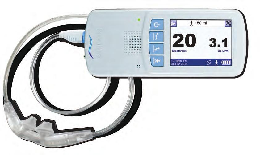
11 2 SYSTEM OVERVIEW VENTILATION SYSTEM COMPONENTS The NIOV Ventilation System is an ultra-lightweight, wearable, system designed to improve breathing by providing increased ventilation to adult respiratory patients when they need it. Because of the system s portability, patients have greater mobility and can move about freely and easily. The NIOV Ventilation System consists of the ventilator, Breathe Pillows Interface, oxygen hose, battery charger, purge tube, and belt clip. The ventilation system is intended for use by patients in the home or institutional setting. Note: The ventilation system does not include source gas cylinder. Shipping configurations may vary based on prescription. Note: NIOV ventilator is compatible with medical grade compressed Oxygen and dry Air. Air Source Gas Regulator and supply hose are sold separately. Contact Breathe Technologies for more information. TIP: The ventilator is shipped in a specially designed, protective box. Do not throw away the box. Keep it for future transportation needs. 1 Purge tube 2 Oxygen cylinder (not included) 3 Oxygen regulator 4 Oxygen supply hose 5 Ventilator 6 Belt clip 7 Pillows Interface (shipped separately) 8 Battery charger 5

12 BREATHE PILLOWS INTERFACE The Breathe Pillows Interface for use with the ventilator is not included with the ventilation system components and is shipped separately. For instructions on how to fit, adjust, and connect the interface, see the section Using the NIOV Ventilation System in this manual and refer to the Breathe Pillows Interface Quick Start guide included with each interface. VENTILATOR FEATURES The following illustrations identify the ventilator buttons and connections. WARNING: Use the NIOV Ventilation System only with the Pillows Interface. If the ventilation system is used with another manufacturer s interface, the ventilator may not function correctly and you may not receive appropriate respiratory therapy. CAUTION: Use a Pillows Interface for a maximum of 30 days. If an interface is used for more than 30 days, its performance may degrade and you may not receive adequate respiratory therapy. Do not use a Pillows Interface that is cracked, odorous, broken, or kinked. If a damaged interface is used, you may not receive adequate respiratory therapy. 1 Touch screen 2 Activity buttons 3 Power button 4 Power light 5 Speaker 6 Backup alarm buzzer 7 Breath indicator light 6


13 2 SYSTEM OVERVIEW Top End of Ventilator Activity and Power Buttons Low Activity button Medium Activity button High Activity button 1 Battery charger connection 2 Alarm Silence button 3 Not used Bottom End of Ventilator Power button TURNING THE VENTILATOR ON AND OFF 1 Interface port 2 Source Gas supply connection WARNING: Do not cover the ventilator speaker or backup alarm buzzer with tape or any other object. Covering the ventilator speaker or buzzer may make it difficult for a patient to hear alarms, which may result in inadequate respiratory therapy. 1 Power button To turn the ventilator on, press the Power button. To turn the ventilator off, press the Power button for approximately three seconds. 7


 Note: Your Home screen will display O2 or Air based on the source gas option")
14 Turn On Sequence When you turn on the ventilator, the green power light is illuminated. The ventilator performs a self test. During the test, all indicator lights should briefly flash and an audible alarm should briefly sound. This self test can take up to 15 seconds to complete. If you do not hear an audible alarm when you turn on the ventilator, contact your health care provider. Home screen if used with Air. 1 Green power light is on. Home screen if used with Oxygen. 3 Home screen is displayed without data. 2 Test screen is displayed. (The software version in this screen is for illustration purposes only.) Note: Your Home screen will display O2 or Air based on the source gas option prescribed by your physician. 4 When the Home screen is displayed, the touch screen is ready to use. CAUTION: Verify that the correct source gas is connected to the ventilator. 8

15 2 SYSTEM OVERVIEW TOUCH SCREEN FEATURES The NIOV Ventilation System uses a touch screen for setting up the ventilator, monitoring patient data, and displaying alarm information. To use the touch screen, simply touch a screen button or an area of the screen you want to make active. An audible click indicates the feature you touch is activated. There are two main ventilator screens: the Home screen and the Menu screen. Home Screen When you turn on the ventilator, after it completes a self test, the touch screen displays the Home screen. After the source gas supply is connected and the patient is wearing the Pillows Interface, when you press a ventilator Activity button, the Home screen displays patient gas flow rate and breath rate. The following illustration shows the buttons, icons, and information displayed on the Home screen. 1 Touch the Wrench button to go to the Menu screen. 2 Current Activity icon and augmentation volume. 3 Touch the Flip button to flip the screen Current breaths per minute (BPM). 5 Average flow in liters per minute, based on activity setting and patient s current breath rate. 6 Battery Charge icon. 7 Current Activity icon. Use the ventilator Activity buttons to change an activity setting. 8 Vibration icon indicating ventilator is in vibration mode. 9 Time and date display. Note: The Wrench and Flip buttons at the top of the screen and the time and date, current Activity icon, and Battery Charge icon at the bottom are displayed on all screens. 9

16 Menu Screen Use the Menu screen to go to the Settings menu, get information about the software version of the ventilator and ventilator use, or go back to the Home screen. To get to the Menu screen, on any ventilator screen, touch the Wrench button. 1 Touch the Wrench button to go to the Menu screen. 1 Screen title. 2 Touch to go to the Home screen. 3 Touch to go to the Settings screen for Trigger Sensitivity, and Utilities. 4 Touch to go to the Software Version screen for software version and total use time. Moving Between the Home Screen and Menu Screen 2 Touch the Home Screen button to go to the Home screen. TOUCH SCREEN ENERGY- SAVE MODE After two minutes with no user interaction, the touch screen automatically enters energysave mode and dims the screen. Touching the screen again will reactivate it and display the Home screen. 10
17 3 CHAPTER USING THE VENTILATION SYSTEM set up and use the NIOV Ventilation System. Step 1. Check the Battery Charge This section describes the six basic steps you need to perform to Step 2. Connect and Turn on a Source Gas Supply Step 3. Connect and Wear the Pillows Interface Step 4. Attach the Ventilator Step 5. Turn On the Ventilator and Choose an Activity Setting Step 6. Adjust the Trigger Sensitivity


18 STEP 1: CHECK THE BATTERY CHARGE The Battery Charge icon appears on every touch screen. Before you use the ventilator, check that the battery is fully charged. This icon Means this Charging ~Fully charged ~¾ charged ~½ charged 1 Press the Power button to turn on the ventilator. ~¼ charged Less than 1 /6 Empty battery, no charge, or status unknown 2 Check that the fully charged Battery Charge icon is displayed before using the ventilation system. It takes approximately three hours to fully recharge the battery when the ventilator s power is turned off,. A fully charged battery should last approximately four hours. Assemble the Battery Charger and Charge the Battery If the ventilator is off, the battery charger light turns green when the battery is fully charged. The ventilator can be on and in use while the battery is charging, but the battery charger light will remain red. Although the ventilator can be charged while in use, it is recommended that the ventilator is charged with the power off to ensure a full charge. Check the Battery Charge icon on the touch screen to see the current battery charge level. 12

19 3 USING THE VENTILATION SYSTEM STEP 2: CONNECT AND TURN ON A SOURCE GAS (OXYGEN OR AIR) This section gives instructions on connecting the ventilator to a source gas, turning the source gas on and off, and replacing source gas cylinder. Note: Only the oxygen cylinder connection is demonstrated in the following instructions. 1 Connect the battery charger cord to the ventilator charger port. The word UP on the battery charger cord will be facing the front of the ventilator. 2 Plug the power cord of the battery charger assembly into the battery charger. 3 Plug in the wall plug. Note: the ventilator can be used while the battery is charging. CAUTION: Do not place the battery charger on wet surfaces or use in wet environments. Wet environments may damage the battery charger and may cause electric shock. CAUTION: Use only the Breathe Technologies approved battery charger and cord set with the ventilator. If an unauthorized battery charger or cord set is used with the ventilator, the ventilator may be damaged. 13 WARNING: If the NIOV Ventilation System is not used with a regulator capable of psig (nominal 50 psig) with greater than 28 LPM capability, you may not receive appropriate respiratory therapy. CAUTION: Use only a Breathe Technologies approved supply hose with the ventilator. If an unauthorized supply hose is used with the ventilator, the ventilator may be damaged. TIP: Use a regulator to regulate the pressure to psig (50 psig nominal) before attaching source gas to the ventilator. Refer to the regulator and source gas supply manufacturers instructions. TIP: The source gas supply hose should remain connected to the ventilator at all times, except when required to be disconnected for maintenance, testing, or replacement. If it is disconnected while the ventilator is on and a therapy level active, an alarm occurs. If this happens, turn the ventilator off, and reconnect the hose. TIP: The NIOV System can work using most common medical grade oxygen and air cylinders when using the appropriately rated regulator. Ensure the appropriate regulator for the cylinder is being used before connecting NIOV. Information about the oxygen cylinder and its specific regulator requirements may be found by contacting the cylinder supplier.


20 Connecting the Regulator to an Oxygen Cylinder 3 Ensure the barbed outlet airflow gauge is set to 0. 1 Slide the regulator over the neck of the cylinder, and line up the pins on the regulator with the holes in the cylinder neck. Connecting the Ventilator to an Oxygen Cylinder 2 Tighten the tee screw on the regulator by turning the handle clockwise. 1 Turn the ventilator off by firmly pressing the Power button for about three seconds. CAUTION: Verify that the correct source gas is connected to the ventilator. 14


21 3 USING THE VENTILATION SYSTEM 4 With the ventilator power off and the oxygen supply hose connected to the ventilator and oxygen supply, follow the regulator and oxygen supply manufacturers instructions for turning on the oxygen supply. 2 Push the small oxygen supply hose connector onto the oxygen supply connection until it snaps into place. Replacing Source Gas Cylinder When a source gas cylinder needs to be replaced: 1 Turn the ventilator off by firmly pressing the Power button for at least three seconds. 2 Follow the cylinder and regulator manufacturers instructions for shutting off the source gas supply. 3 Disconnect the ventilator source gas supply hose from the cylinder. 4 Connect the ventilator source gas supply hose to a new cylinder. 5 Follow the source gas and regulator manufacturers instructions for turning on the cylinder. 3 Connect the green oxygen supply hose connector to the oxygen regulator by turning it clockwise. 15


22 STEP 3: CONNECT AND WEAR THE PILLOWS INTERFACE Before using the Pillows Interface, visually inspect it for damage. The interface comes in four sizes: extra small, small, medium, and large. Your health care provider determines what size is best for you. The interface assembly is packaged clean but not sterile. Connecting the Interface to the Ventilator 1 Turn off the ventilator. 1 Tube fit adjustor 2 Ventilator connector 3 Interface tubing 4 Interface pillows 2 Plug the interface into the ventilator port. 16


23 3 USING THE VENTILATION SYSTEM Wearing the Interface 1 Place the interface in front of you with the arrows underneath pointing up and the curve of the interface towards you. 3 Adjust the tubing length under the chin so that the interface is comfortably secured. 2 Loop the interface tubing over the ears so the pillows of the interface are positioned snugly inside the nostrils. For proper positioning of the interface, see the next section in this Step: Checking the Interface Positioning. 17

24 Checking the Interface Positioning The interface is placed correctly if the following conditions are met: The interface pillows rest snugly inside the nostrils, as shown. TIP: When the interface is in use, periodically check that it is positioned correctly and make adjustments as required. If skin becomes irritated, stop using the device, and contact your health care provider. The fit is comfortable. The interface does not make breathing difficult. Air does not flow to the eyes, cheeks, or lips. If any one of these conditions is not met, reposition the interface. If problems persist, contact your health care provider. 18


25 3 USING THE VENTILATION SYSTEM STEP 4: ATTACH THE VENTILATOR You can attach the ventilator to a belt or waistband. Instructions here describe how to use the belt clip to attach the ventilator to a belt or waist band. The ventilator can be worn on either the right or left side. CAUTION: Make sure the clip is securely fastened to the belt and the ventilator. If the clip is not securely fastened to the belt or the ventilator, the ventilator may drop and be damaged. STEP 5: TURN ON THE VENTILATOR AND CHOOSE AN ACTIVITY SETTING 1 Position the clip over the belt, and push down until it is secure. When you first turn on the ventilator, no activity setting is active. The three Activity buttons on the ventilator (Low Activity, Medium Activity, High Activity) correspond to three different augmentation volumes prescribed by a physician. Choose an Activity button appropriate for your level of activity. You can change the level at any time. 2 Line up the belt clip with the ventilator sockets, and push down until the clip audibly snaps into place. 19


26 STEP 6: ADJUST THE TRIGGER SENSITIVITY 1 Turn on the ventilator. 2 Press an Activity button for about one second until you hear a tone that indicates it is active. Trigger sensitivity determines how easily your breath triggers the ventilator to deliver oxygen. For shallow breathing, set the trigger sensitivity to a low number. You can choose a setting between 0 and 9. Zero is the most sensitive and 9 is the least sensitive setting. Getting to the Trigger Sensitivity Screen 3 Confirm the selected Activity icon is displayed on the touch screen (High Activity shown). 1 On any ventilator screen, touch the Wrench button. 20


27 3 USING THE VENTILATION SYSTEM Changing Trigger Sensitivity 2 On the Menu screen, touch Settings. 1 On the Trigger Sensitivity screen, touch the Up arrow to increase the value or the Down arrow to decrease it. If you press and hold an arrow, the number automatically increases or decreases. Note: The lower the number, the more sensitive the setting. 2 When you are finished, touch OK. 3 On the Settings Menu screen, touch Trigger Sensitivity. 3 In the message asking if the settings are OK, touch Confirm. Note: Changes to settings only take effect when you touch Confirm. 21

28 4 CHAPTER ALARMS AND TROUBLESHOOTING This section describes the alarm functions and possible troubleshooting solutions. Audio Alarm Sounds Alarm Message Display Active Alarms Window Silencing and Clearing Alarms Summary NIOV Ventilation System Alarms Additional Troubleshooting Situations
29 4 ALARMS AND TROUBLESHOOTING An alarm indicates a condition that needs to be identified and resolved. There are three alarm priority levels: high, medium, and low. This section describes alarm priority levels, the alarm messages displayed at the top of the touch screen, and the Active Alarms window. The section also includes tables that list the possible causes of an alarm and the options for resolving it. ALARM MESSAGE DISPLAY When an audible alarm occurs, an alarm message flashes at the top of the touch screen. The priority level of an alarm is indicated by the color and the rate at which the message flashes. AUDIO ALARM SOUNDS Each alarm priority level has a distinct sound, described as follows: Alarm Priority Levels and Corresponding Sounds Alarm priority: High-priority alarm Sound: Sequence of two sets of five tones Alarm priority: Medium-priority alarm Sound: Sequence of three tones Alarm priority: Low-priority alarm Sound: Single tone A red, rapidly flashing alarm message is a high-priority alarm and indicates a situation that requires immediate attention. A yellow, steadily flashing alarm message is a medium-priority alarm and indicates a potentially hazardous situation that must be resolved in a timely manner. A blue, non-flashing alarm message is a lowpriority alarm and indicates a problem that is not hazardous but should be resolved. 23

.")
30 ACTIVE ALARMS WINDOW Multiple alarms may occur at the same time. Touch the Active Alarms button at the top of the touch screen to display a list of active alarms. 1 Touch the Active Alarms button to display the alarm list. 2 Alarm icon. 3 Scroll Down arrow. 4 Scroll Up arrow. 1 Alarm message alternates between each occurring alarm. 2 Alarm Silenced icon. 3 Alarm Silenced icon is displayed when all alarms are silenced. TIPS: The Active Alarms window displays up to three alarms, from highest to lowest priority (red, yellow, blue). If there are more than three alarms, you can use the Scroll Up and Scroll Down arrows to scroll through the list. 24


31 4 ALARMS AND TROUBLESHOOTING SILENCING AND CLEARING ALARMS SUMMARY Silencing and clearing alarms is a multi-step process that depends on alarm priority and how many alarms are active. 2 Resolve the condition that triggered the alarm. For help resolving alarms, see the alarm and troubleshooting tables that follow for possible causes of an alarm and options to resolve it. If an alarm silence button is pressed but not resolved, the alarm will sound again after 60 seconds. 3 After resolving a high-priority alarm, touch OK in the message that indicates the alarm has been resolved. 1 Silence Alarm button. Press the Silence Alarm button to temporarily silence the alarm for 60 seconds. Pressing the Silence Alarm button silences only one alarm at a time in audible or vibrating alarm mode. If more than one alarm occurs, press the Silence Alarm button once for each alarm. If the alarm is a medium- or high-priority alarm and is not silenced after 60 seconds, the alarm will resume with an additional buzzer. Message indicating a high-priority alarm has been resolved. 25
32 NIOV VENTILATION SYSTEM ALARMS The following tables list high-, medium-, and low-priority alarms. For each alarm, the tables list the screen message, the possible causes for the alarm, and the checks and options for resolving it. High-Priority Alarms Screen Alert Cause Checks and Possible Resolution High Temperature High Circuit Pressure High PEEP Pressure CPU or battery temperature is above the allowable limit. Interface may be pinched or kinked. Interface may be blocked. Check to make sure the ventilator is: Not near a heat source. In a well ventilated area. Not covered or enclosed. Check the interface tube. Replace it if it is pinched or kinked. Inspect and clean the interface per the instruction for cleaning the interface. Medium-Priority Alarms Screen Alert Cause Checks and Possible Resolution Breath Timeout No breath is detected for 20 or 60 seconds, depending on the setting. Patient is not breathing or breath is too shallow to trigger augmentation. Note: The ventilator is not indicated for patients who are not spontaneously breathing with a minimum volume of 3.5 ml/kg. Inspect and clean the interface per the instruction for cleaning the interface. 26
33 4 ALARMS AND TROUBLESHOOTING Medium-Priority Alarms High Breath Rate Respiratory rate exceeds the set limit. Patient is breathing faster than the rate set by a clinician. Inspect and clean the interface per the instruction for cleaning the interface. Screen Alert Cause Checks and Possible Resolution High Del. Pressure High Gas Pressure Low Breath Rate Low Del. Pressure Low Gas Pressure System Fault Interface pressure during delivery exceeds the maximum expected. Source gas pressure exceeds the allowable limit. Respiratory rate falls below the set limit. Interface pressure during delivery fails to exceed the minimum expected. Source gas pressure drops below the allowable limit. Internal fault detected during operation. Check the interface. Replace it if the tubing is torn, bent, or kinked. Make sure the tubing is not pinched or crushed. Use a regulator to adjust the source gas pressure to within the acceptable range of psig (50 psig nominal). Patient s breathing is too shallow to consistently trigger augmentation. Inspect and clean the interface per the instruction for cleaning the interface. Patient is breathing through the mouth. Check the interface connection to the ventilator. Check the interface. Replace it if it is leaking. Check the source gas input pressure. If it is <41 psig, use a regulator to adjust it within the acceptable range of psig (50 psig nominal). Check the source gas supply to ventilator connections. Check the source gas supply level. Check the source gas supply to ventilator connections. Check the source gas supply regulator. Check that the source gas cylinder valve is fully open. If a system fault occurs, in the message to reboot the ventilator, touch OK. Turn off the ventilator, and turn it on again. If system fault persists, continue with your prescribed backup therapy and contact your health care provider. 27
34 Very Low Battery Current battery capacity drops below 15%. Recharge the battery. If the battery does not recharge, contact your health care provider. Low-Priority Alarms Screen Alert Cause Checks and Possible Resolution Battery Low Battery capacity drops below 25%. Recharge the battery. If the battery does not recharge, contact your health care provider. System Fault System fault detected during power on. If a system fault occurs, in the message to reboot the ventilator, touch OK. Turn off the ventilator, and turn it on again. If system fault persists, continue with your prescribed backup therapy and contact your health care provider. ADDITIONAL TROUBLESHOOTING SITUATIONS The following table lists situations that may occur during normal use of the ventilation system that do not have an alarm associated with them. The possible causes and options for resolving these situations are also listed. Additional Troubleshooting Situations Observation Cause Possible Resolution Breath indicator light is not flashing with the patient s breathing. Patient s breath is too shallow to trigger augmentation. Secretions may have built up on the pillows of the interface, blocking delivery of air. Patient is mouth breathing. Change the trigger sensitivity setting to a lower setting. Inspect and clean the interface per the instruction for cleaning the interface. Instruct patient to breathe in through their nose (purse lipped breathing is acceptable). 28
35 4 ALARMS AND TROUBLESHOOTING Additional Troubleshooting Situations Observation Cause Possible Resolution Breath indicator light is not flashing. Buzzer sounds continuously at a constant pitch for two minutes or more. Gas delivery is causing coughing or irritation in airway. No volume output. Source gas supply does not last as long as expected. A ventilator Activity button has not been pressed. Secretions may have built up on the pillows of the interface, blocking delivery of air. The ventilator battery is internally disconnected. The backup buzzer will sound for two to five minutes before it is silenced. Interface is not positioned correctly. Source gas supply is disconnected. Source gas supply is empty. Ventilator is not on. Battery is depleted. Ventilator is inoperative. Incorrect source gas supply hose being used. User breath rate is higher than expected. Source gas supply is not full at the start of use. The regulator is not properly connected to the cylinder. The regulator may have a leak. Press an Activity button. Inspect and clean the interface per the instruction for cleaning the interface. Contact your health care provider. If symptoms persist, stop treatment with the ventilator, and contact your physician. Reconnect the source gas supply. Replace the source gas supply. Turn the ventilator on. Recharge the battery. If there is no volume output, contact your health care provider. Ensure the correct source gas supply hose (Oxygen or Air) is connected. Refer to source gas supply Information chart Obtain a new source gas supply. Reconnect the gas regulator to the cylinder. The regulator sealing washer connecting to the cylinder may be worn or damaged. Contact your healthcare provider. 29
36 Observation Cause Possible Resolution Ventilator battery does not last as long as expected after a recharge. Ventilator is autocycling (delivering gas without being triggered by the patient s breathing or delivering gas multiple times during one breath). Ventilator is triggering during exhalation. Ventilator sometimes misses breaths. Ventilator sounds like it is triggering, but no gas is being delivered. The source gas supply hose does not connect to the cylinder. Battery is not charged completely. Battery life is nearing its end. Battery has become untrained. Secretions have built up on the pillows of the interface. Ventilator is triggered by movement of the interface. Ventilator is in breath timeout mode, with timeout augmentation set to 12 BPM. Secretions have built up on the pillows of the interface. User is breathing faster than 40 BPM. Secretions have built up on the pillows of the interface. No oxygen supply is connected. Incorrect source gas supply hose being used. Recharge battery. Contact your health care provider. Retrain the battery, as shown in section 5. Inspect and clean the interface per the instruction for cleaning the interface. Adjust trigger sensitivity to a higher number. Inspect and clean the interface per the instruction for cleaning the interface. It is normal for the ventilator to limit augmentation to less than 40 BPM. Inspect and clean the interface per the instruction for cleaning the interface. Reconnect oxygen supply. Connect the appropriate source gas supply hose (Oxygen or Air). 30

37 5 CHAPTER SETUP AND CARE This section describes how to change settings using the Utilities menu and instructions on basic care of the system. Changing Ventilator Settings Setting Time and Date Setting Vibration Mode Setting Audio Loudness Adjusting Screen Brightness Viewing Software Version Information Caring for the NIOV Ventilation System Battery Retraining and Replacement Oxygen Supply Information
38 This section describes how to change settings using the Utilities menu and display the Information screen, which shows the ventilator software version and the total time the ventilator has been in use. This section also gives instructions on basic care of the ventilation system. CHANGING VENTILATOR SETTINGS 2 On the Menu screen, touch Settings. With the Utilities menu, you can change the time and date, brightness of the touch screen, volume of audible alarms, and set alarms to vibrate mode. Getting to the Utilities Menu 3 On the Settings Menu screen, touch Utilities. (The Clinician s Settings menu is for clinician use only.) 1 On any ventilator screen, touch the Wrench button. 32


39 5 SETUP AND CARE SETTING TIME AND DATE 1 On the Utilities Menu screen, touch Set Time/Date. 3 Touch the Up arrow to increase the value in the box or the Down arrow to decrease it. If you press and hold an arrow, the value automatically increases or decreases. 4 Repeat steps 2 and 3 for each box you want to change, and then touch OK. 2 On the Set Time/Date screen, touch the box you want to change. 6 In the message asking if the settings are OK, touch Confirm. Note: Changes to settings only take effect when you touch Confirm. 33


40 SETTING VIBRATION MODE The Set Vibration screen lets you change alarms from audible tones to a vibration. However, if a low- or medium-priority vibrating alarm occurs and is not resolved in 60 seconds, an audible alarm occurs. For a high-priority alarm, an audible tone immediately occurs with a vibration alarm with no delay. 2 On the Set Vibration screen, touch On or Off. 3 When you are finished, touch OK. 1 On the Utilities Menu screen, touch Set Vibration. 4 In the message asking if the settings are OK, touch Confirm, and check that the Vibrate icon appears at the bottom of the touch screen, indicating the ventilator is in vibrate mode. Note: Changes to settings only take effect when you touch Confirm. 34
41 5 SETUP AND CARE SETTING AUDIO LOUDNESS 1 On the Utilities Menu screen, touch Set Loudness. 4 In the message asking if the settings are OK, touch Confirm. Note: Changes to settings only take effect when you touch Confirm. ADJUSTING SCREEN BRIGHTNESS 2 Touch the Up arrow to increase the volume level or the Down arrow to decrease it. If you press and hold an arrow, the number automatically increases or decreases. You can choose a loudness level between 1 and 5, with 5 being the loudest and 1 the quietest. 3 When you are finished, touch OK. 1 On the Utilities Menu screen, touch Set Brightness. 35


42 VIEWING SOFTWARE VERSION INFORMATION The Software Version screen displays the software version number, its release date, and the ventilator s total operating time. 2 Touch the Up arrow to increase the brightness or the Down arrow to decrease it. If you press and hold an arrow, the number automatically increases or decreases. You can choose a brightness level between 1 and 5, with 5 being the brightest and 1 the dimmest. 3 When you are finished, touch OK. Getting to the Software Version Screen 1 On any ventilator screen, touch the Wrench button. 4 In the message asking if the settings are OK, touch Confirm. Note: Changes to settings only take effect when you touch Confirm. 2 On the Menu screen, touch Information. 36

43 5 SETUP AND CARE Check the source gas supply hose and the interface for leaks and loose or damaged cabling or connectors. The screen displays software version, serial number, and total operating time. CARING FOR THE NIOV VENTILATION SYSTEM This section gives instructions on how to care for the NIOV Ventilation System, including daily visual checks and guidelines for cleaning and storage. Daily Visual Checks Look at the ventilation system components daily. If you uncover any of the following, do not use the ventilation system. Contact your health care provider for instructions on servicing or replacing damaged ventilation system components. Check for cracks in the ventilator casing. Check the ventilator for loose or damaged buttons, connectors, or other control and alarm components. Alarm Checks Confirm that when the ventilator is turned on, it makes audible tones. If tones are not heard, the ventilator should be returned to your health care provider for servicing. Cleaning the Ventilator Wipe the external surfaces of the ventilator with 70% isopropyl alcohol as necessary and between uses. Clean the touch screen with a soft microfiber cloth. CAUTION: 70% isopropyl alcohol may damage the touch screen. When cleaning external surfaces of the ventilator with 70% isopropyl alcohol, avoid contact with the touch screen. Cleaning External Surfaces of the Pillows Interface If mucus accumulates on the pillows of the interface, use a clean cloth to remove it. If dirt is visible on the outside of the interface, use a clean cloth and mild detergent to remove it. 37


44 Periodic Cleaning and Purging of the Pillows Interface Periodically clean the interface following these steps: 1 Disconnect the interface from the ventilator. 2 Submerge the interface end of the interface in a clean container of warm water suitable for drinking, and agitate the interface to clean it. 3 Remove the interface from the water, and hang it so excess water drains from the interface. 4 Before reusing the interface, perform a purge to clear any excess water that may impede air flow. For purging instructions, see the section Purging the Pillows Interface that immediately follows. WARNING: Do not subject the Pillows Interface to heat sterilization, hot water pasteurization, autoclaving, radiation sterilization, ethylene oxide gas sterilization, or attempt to clean it in a dishwasher or microwave oven. Doing any of these may damage the interface and impair oxygen delivery. Purging the Pillows Interface After cleaning the interface or when you suspect dust or debris has entered the air-flow passage, purge the interface. Purge tube The steps below demonstrate purging instructions when using an oxygen regulator. If using medical grade air as source gas, a flow meter such as the one shown below will be required. Additional connectors may also be required. 38


45 5 SETUP AND CARE 1 Slide the regulator over the neck of the cylinder, and line up the pins on the regulator with the holes in the cylinder neck. 3 Place the larger end of the purge tube over the barbed outlet. 4 Open the oxygen main valve according to the cylinder and regulator manufacturers instructions. 2 Tighten the tee screw on the regulator by turning the handle clockwise. 5 Rotate the barbed outlet flow regulator to 4 LPM. 39

46 Environment Specifications Do not use the NIOV Ventilation System if the ambient temperature is greater than 104 F (40 C) or less than 5 C (41 F). BATTERY RETRAINING AND REPLACEMENT 6 Firmly press and hold the smaller end of the purge tube over one of the interface ports that connects the interface to the ventilator. Take care not to slide the tube over the O-ring of the port. Hold the purge tube over the interface port until all the water is purged from the tube. 7 Repeat step 6 for the other interface port. 8 Rotate the barbed outlet flow regulator to the zero or OFF position. 9 Shut off the oxygen main valve according to the cylinder and regulator manufacturers instructions. 10 Remove the purge tube from the barbed outlet. Maintenance The NIOV Ventilation System does not require calibration or routine maintenance. Preventive maintenance, including replacing the source gas supply hose, is required after 2½ years of use. Contact your health care provider to make arrangements for preventive maintenance. Battery Retraining After a battery has been charged numerous times, the battery charge icon may not accurately display the battery charge. For example, after fully charging the battery, the battery charge icon may only display 3 bars instead of 4. In this case, the battery has more charge than the battery charge icon indicates. Or, the battery charge icon may display 2 bars when the charge is really only 1. In this case, the battery has less charge than the battery icon indicates. If you notice that the battery seems to last longer or shorter than the battery charge icon suggests, you may need to retrain the battery so the icon more accurately displays the battery charge. Retraining the battery involves discharging it fully and then recharging it fully until the battery icon on the touch screen accurately reflects a full charge and no charge. 40
47 5 SETUP AND CARE To retrain a battery follow these steps: 1 Turn on the ventilator, press an Activity button, and let the battery discharge fully until the ventilator shuts itself off. 2 Confirm the ventilator is off. Connect the wall battery charger to the ventilator. Confirm that the charger light is red. 3 Let the ventilator charge until the charger light turns green. 4 Turn the ventilator on. Check that the battery charge icon displays four white bars. If it does not, repeat steps 2-4. If after repeating steps 2-4 a second time, the ventilator still does not show four white bars, contact your health care provider. OXYGEN SUPPLY INFORMATION The NIOV ventilator is compatible with compressed medical oxygen cylinders and hospital wall oxygen. The duration of compressed medical oxygen cylinders depends on the volume of the cylinder and the breathing pattern of each patient, which can change throughout the day. Observe your daily oxygen consumption a few times before estimating typical use. The following tables can be used to obtain approximate values only. Battery Replacement The internal ventilator battery is not serviced in the field. It should be replaced when runtime degrades to an unacceptable level. Contact your Breathe Technologies service provider to make arrangements for replacing the battery. 41
48 Cylinder size B: 164 liters (M-6) Breaths per minute (BPM) Tidal volume (ml) Duration in hours Cylinder size D: 425 liters (M-15) Breaths per minute (BPM) Tidal volume (ml) Duration in hours Cylinder size E: 660 liters Breaths per minute (BPM) Tidal volume (ml) Duration in hours
49 CHAPTER 6ICONS Icon Where used Meaning Ventilator, touch screen Ventilator, touch screen Ventilator, touch screen On ventilator, Low Activity button delivers augmentation volume at rate set by clinician in ventilator Clinician s Settings menu. Displayed on the Volume Settings screen as a label for the Low Activity augmentation value set by clinician. Displayed on each ventilator screen if augmentation volume delivery is set to Low Activity. On ventilator, Medium Activity button delivers augmentation volume at rate set by clinician in ventilator Clinician s Settings menu. Displayed on the Volume Settings screen as a label for the Medium Activity augmentation value set by clinician. Displayed on each ventilator screen if augmentation volume delivery is set to Medium Activity. On ventilator, High Activity button delivers augmentation volume at rate set by clinician in ventilator Clinician s Settings. Displayed on the Volume Settings screen as a label for the High Activity augmentation value set by clinician. Displayed on each ventilator screen if augmentation volume delivery is set to High Activity. 43
50 Icon Where used Meaning Ventilator Ventilator power on/off button. Ventilator Ventilator Indicates communication port. This port is only used by the manufacturer. Orientation marker for power-in port. Ventilator and Product label Ventilator Touch screen Touch screen Touch screen Touch screen Touch screen Touch screen Indicates direct current and denotes the location where the battery charger is plugged into the ventilator. On the ventilator, the Alarm Silence button turns off vibrator or audible alarm. Displayed in the Active Alarms window of the touch screen if an active alarm has not been silenced. Displayed in the Active Alarms window of the touch screen if an active alarm has been silenced. Displayed on the bottom of each ventilator screen if all active alarms have been silenced. Displayed on each ventilator screen if battery status is unknown or charge is critically low. Displayed on each ventilator screen if battery has approximately 1 /6 of its charge remaining. Displayed on each ventilator screen if battery has approximately ¼ of its charge remaining. Displayed on each ventilator screen if battery has approximately ½ of its charge remaining. 44
51 6 ICONS Icon Where used Meaning Touch screen Touch screen Touch screen Touch screen Touch screen Touch screen Product label Displayed on each ventilator screen if battery has approximately ¾ of its charge remaining. Displayed on each ventilator screen if battery charge is approximately full. Displayed on each ventilator screen if battery is charging. Displayed on each ventilator screen. Touching the Wrench button displays the Menu screen. Displayed on each ventilator screen. Touching the Flip button rotates the touch screen 180. Displayed on each ventilator screen if the ventilator is in vibrate mode. Indicates BF type equipment. Device isolates the patient from any live voltage in the equipment. IPX1 Product label Indicates device is protected against dripping water. Product label Product label and documentation Product label Indicates a class II device. Device is double insulated and does not require a safety connection to electrical earth (US: ground). On product indicates accompanying documentation includes important information that must be read before using device. Indicates product emits non-ionizing radiation. 45
52 Icon Where used Meaning Product label Product label Product label Product label Indicates product is a Bluetooth wireless compatible devise that emits radio frequency waves. Indicates disposal of device must conform to Waste in Electrical and Electronic Equipment Directive 2002/96/EC. Indicates manufacturer and denotes the location of the manufacturer name, address. Indicates date of manufacture. O2 Product label Indicates oxygen and denotes the location where the oxygen hose attaches to the ventilator. Product label Product label Battery charger label Battery charger label Battery charger label Battery charger label Indicates catalog number and denotes the location of the part number for the device. Indicates serial number and denotes the location of the serial number for the device. Indicates product meets US standards for use with medical electrical equipment. On battery charger indicates indoor use only and denotes that it should only be used indoors. On battery charger indicates battery charge. The black shaded area represents the amount of charge within the battery (here shown with ~80% charge). On battery charger indicates battery charger meets European economic area standards for use with medical electrical equipment and information technology equipment. 46
53 INDEX A activity settings and buttons buttons and icons representing 6 choosing or changing a setting 19 alarms active alarms window 24 additional alarm troubleshooting 28 alarm checks 38 alarm message display 23 backup alarm buzzer 6 high-priority alarms 26 low-priority alarms 28 medium-priority alarms 26 silencing and clearing 25 sounds and priority levels 23 audio setting loudness 35 augmentation volume icons representing 9 corresponding to activity settings 19 B battery assemble and charge 12 check the battery charge 12 icons representing charge 12, 44 low charge alarm 28 retraining and replacement 40 troubleshooting charge duration 30, 41 very low charge alarm 27 assembling 12 belt clip attaching to ventilator 19 breath rate displayed on Home screen 9 high breath rate alarm 26 low breath rate alarm 27 C cleaning cleaning the interface 38 cleaning the ventilator 38 purging the interface 38 clinical considerations for use 2 compliance and IEC classification 66 H home screen 8 I icons 43 battery charger 47
54 INDEX interface checking position 18 cleaning 38 connecting to ventilator 16 length of use 38 wearing 17 purging 38 M maintenance of ventilation system 40 menu screen 10 O oxygen regulator connecting to oxygen cylinder 14 oxygen supply compatible cylinders with ventilator 5 connecting and turning on 13 duration of cylinders 41 no volume output 29 regulating pressure of 13 replacing cylinders 15 shorter than expected duration 29 oxygen supply hose when to disconnect 13, 15 P patient participation required for ventilator use 2 S safety information 3 screen brightness adjusting 35 settings menu accessing 32 setup and care 31 software version information 36 source gas supply (oxygen or air) compatible cylinders with ventilator 5 connecting and turning on 13 duration of cylinders 41 no volume output 29 regulating pressure of 13 replacing cylinders 15 shorter than expected duration 29 symbols and conventions warnings, cautions and tips 2 48

55 INDEX T time and date setting 33 touch screen energy-save mode 10 features 9 trigger sensitivity adjusting 20 troubleshooting alarms 2, 26 troubleshooting situations 28 U utilities menu 32 V adjusting screen brightness 35 adjusting trigger sensitivity 20 caring for 37 changing settings 32 choosing an activity setting 19 cleaning 37 connecting to oxygen cylinder 14 features 6 home screen 8 icons 43 menu screen 10 system overview 4 touch screen energy-save mode 10 touch screen features 9 turning on and off 8 vibration mode setting 34 W warranty i ventilation system caring for 37 daily alarm checks 38 daily visual checks 37 environment specifications 40 system components 5 ventilator 49

56 INDEX 50
Table of Contents. Operating Instructions. Resource v.2 Conserving Regulator
 Operating Instructions Table of Contents Resource v.2 Conserving Regulator Safety Information Device Precautions Introduction Product Features Product Specifications Feature Illustrations Set Up Usage
patient education program 4156 South 52 nd Street, Omaha, NE ChildrensOmaha.org/HomeHealthcare
 patient education program 4156 South 52 nd Street, Omaha, NE 68117 800-747-7334 402-734-6741 ChildrensOmaha.org/HomeHealthcare We know children CHILDREN S HOME HEALTHCARE Trilogy Ventilator Instructions
Operation and Maintenance of the EPV200 Portable Ventilator
 Operation and Maintenance of the EPV200 Portable Ventilator 1 Applications of the EPV200 The EPV200 Portable Ventilator is a gas powered electronically controlled mechanical ventilator, designed to provide
AUTOVENT 4000 VENTILATOR
 OVERVIEW AUTOVENT 4000 Only properly trained and approved Escambia County Bureau of Public Safety Paramedics are to use the AutoVent 4000 ventilator manufactured by LSP to transport patients already on
BOC: Living healthcare. Manual. LIV IQ BOC Integrated Valve with digital display portable delivery system for Medical Oxygen. BOC: Living healthcare
 BOC: Living healthcare Manual LIV IQ BOC Integrated Valve with digital display portable delivery system for Medical Oxygen. BOC: Living healthcare 02 Manual LIV IQ Oxygen Manual LIV IQ Oxygen 03 Contents.
ACRYLIC FLOW METERS 0-30, 0-70 & LPM
 ACRYLIC FLOW METERS 0-30, 0-70 & 0-120 LPM ASSEMBLY INSTRUCTIONS & INSTRUCTIONS FOR USE R219P86 (0-120LPM) R219P87 (0-70LPM) R219P88 (0-30 LPM) R138P11 Rev. D TABLE OF CONTENTS: 1.0 PRODUCT OVERVIEW...1
Instructions for Use. OptiLife Nasal Lab Mask
 Instructions for Use OptiLife Nasal Lab Mask Intended Use The OptiLife Nasal Mask is intended to provide an interface for application of CPAP or bi-level therapy to patients. The mask is for multi-patient
U S E R M A N U A L CAUTION. SAVE THESE INSTRUCTIONS Federal (USA) law restricts this device to sale by or on the order of a physician.
 law restricts this device to sale by or on the order of a physician.") U S E R M A N U A L 1600 SERIES OXYGEN REGULATOR 168715G (Shown) SAVE THESE INSTRUCTIONS Federal (USA) law restricts this device to sale by or on the order of a physician. 300 Held Drive Tel: (+001) 610-262-6090
U S E R M A N U A L 1600 SERIES OXYGEN REGULATOR 168715G (Shown) SAVE THESE INSTRUCTIONS Federal (USA) law restricts this device to sale by or on the order of a physician. 300 Held Drive Tel: (+001) 610-262-6090
PERSONAL AIR BREATHING UNIT
 PERSONAL AIR BREATHING UNIT Operation & Maintenance Manual MARTECH SERVICES C O M P A N Y 1-800-831-1525 Table of Contents INTRODUCTION: Page 2 COMPONENTS DRAWING: Page 3 START UP: Page 4 OPERATION: Page
Rev. B. Operating Instructions
 780745-00 Rev. B Operating Instructions 780745-00 Rev. B TABLE OF CONTENTS PAGE Warnings, Cautions, and Notes..............................4-7 Definition of Symbols......................................
Operation and Maintenance of the MCV100 and MCV100-B Portable Ventilator
 Operation and Maintenance of the MCV100 and MCV100-B Portable Ventilator 1 Applications of the MCV100(B) The MCV100 and MCV100-B Mass Casualty Ventilators are electronically controlled portable ventilators,
Calibration Gas Instrument INSTRUCTION MANUAL. Release I. Advanced Calibration Designs, Inc.
 Advanced Calibration Designs, Inc. Calibration Gas Instrument INSTRUCTION MANUAL Release I www.goacd.com Instruction Manual Gas Generator Release I TABLE OF CONTENTS I. General Description Page 2 II. Start-Up
My CoughAssist. A patient guide to CoughAssist T70. Please visit
 Philips Healthcare is part of Royal Philips Electronics Europe, Middle East, Africa +49 7031 463 2254 How to reach us www.philips.com/healthcare healthcare@philips.com Latin America +55 11 2125 0744 Asia
DRAFT U S E R M A N U A L CAUTION. Model: 19MFA1001 Series. Federal (USA) law restricts this device to sale by or on the order of a physician.
 law restricts this device to sale by or on the order of a physician.") U S E R M A N U A L Model: 19MFA1001 Series SAVE THESE INSTRUCTIONS Federal (USA) law restricts this device to sale by or on the order of a physician. 300 Held Drive Tel: (+001) 610-262-6090 Northampton,
U S E R M A N U A L Model: 19MFA1001 Series SAVE THESE INSTRUCTIONS Federal (USA) law restricts this device to sale by or on the order of a physician. 300 Held Drive Tel: (+001) 610-262-6090 Northampton,
AND OPERATION INSTRUCTIONS
 ADI 2111-D Certified ISO 9001 MEDICAL FLOWMETER (Back Pressure Compensated Thorpe Tube) INSTALLATION AND OPERATION INSTRUCTIONS Before Installing or Operating, Read and Comply with These Instructions Controls
Oxygen Dialflow Meter. Instructions for Use
 Oxygen Dialflow Meter Instructions for Use 702-0031.12 December 2017 1. Symbols Warning! Caution! Indicates a potentially hazardous situation which, if not avoided, could result in injury to the patient,
2 CYLINDER MOBILE CART USER S MANUAL / INSTRUCTIONS
 Parker Hannifin Corporation Precision Fluidics Division Porter Instrument 245 Township Line Road Hatfield, PA 9440 Office 25-723-4000/Fax 25-723-506 www.porterinstrument.com 2 CYLINDER MOBILE CART USER
Pressure Relief Valve Instruction Manual
 CVR3-M0_062017 Pressure Relief Valve Instruction Manual MODEL: CVR3 SFA Companies 10939 N. Pomona Ave. Kansas City, MO 64153 Tel: 888-332-6419 * Fax: 816-448-2142 E-mail: sales@bvahydraulics.com Website:
Manual: Biphasic Positive Airway Pressure (BiPAP) Ventilation
 Ventilation") RCH@Home Manual: Biphasic Positive Airway Pressure (BiPAP) Ventilation 1. Commonly used terms... 2 1.1 Inspiration... 2 1.2 Expiration... 2 1.3 Breath rate (bpm)... 2 1.4 Ventilation... 2 1.5 Biphasic
RCH@Home Manual: Biphasic Positive Airway Pressure (BiPAP) Ventilation 1. Commonly used terms... 2 1.1 Inspiration... 2 1.2 Expiration... 2 1.3 Breath rate (bpm)... 2 1.4 Ventilation... 2 1.5 Biphasic
Yoke Block Instruction Manual
 Yoke Block Instruction Manual ! WARNING IMPORTANT: READ MANUAL COMPLETELY BEFORE OPERATING THIS DEVICE This manual contains instructions on periodically required checks to be performed by the user. These
Astral in AirView: Improving patient care through connectivity. ResMed.com
 Astral in AirView: Improving patient care through connectivity ResMed.com Using Astral in AirView via the ResMed Connectivity Module (RCM) Astral is ResMed s portable, invasive and non-invasive life support
NB/NBR NITROGEN BOOSTER FOR AVIATION SERVICE
 NB/NBR NITROGEN BOOSTER FOR AVIATION SERVICE INSTALLATION, OPERATION & MAINTENANCE MANUAL INTERFACE DEVICES, INC. 230 Depot Road, Milford, CT 06460 Ph: (203) 878-4648, Fx: (203) 882-0885, E-mail: info@interfacedevices.com
DFB FLOW METERS (DESIGNED FOR BLENDERS, DUAL TAPER)
") DFB FLOW METERS (DESIGNED FOR BLENDERS, DUAL TAPER) 0-3, 0-15, 0-30 & 0-70 LPM ASSEMBLY INSTRUCTIONS & INSTRUCTIONS FOR USE R219P87-400 (0-70 LPM) R219P88-400 (0-30 LPM) R219P79-400 (0-15 LPM) R219P99-400
DFB FLOW METERS (DESIGNED FOR BLENDERS, DUAL TAPER) 0-3, 0-15, 0-30 & 0-70 LPM ASSEMBLY INSTRUCTIONS & INSTRUCTIONS FOR USE R219P87-400 (0-70 LPM) R219P88-400 (0-30 LPM) R219P79-400 (0-15 LPM) R219P99-400
Oxygen Dialflow Meter. Instructions for Use
 Oxygen Dialflow Meter Instructions for Use 702-0031.9 May 2014 1. Symbols Warning! Caution! Indicates a potentially hazardous situation which, if not avoided, could result in personal injury to the user
Yoke Block Instruction Manual
 Yoke Block Instruction Manual ! WARNING IMPORTANT: READ MANUAL COMPLETELY BEFORE OPERATING THIS DEVICE This manual contains instructions on periodically required checks to be performed by the user. These
accidents which arise due to non-observance of these instructions and the safety information herein. SPECIFICATIONS
 18 GAUGE 2 INCH BRAD NAILER Model: 7555 CALIFORNIA PROPOSITION 65 WARNING: You can create dust when you cut, sand, drill or grind materials such as wood, paint, metal, concrete, cement, or other masonry.
C-1 C-7. C-6 Short air tubing Upper Velcro straps. C-a C-5 C-2 C-4 C-3 B-1 B-9 B-10 B-2 B-7 B-8 B-3 B-6 D-1 D-2 D-13 D-3 D-12 D-10 D-11 D-4 D-5 D-8
 A Forehead support Forehead pads C Mask Frame Mask Elbow Cushion clip Mask Cushion C-7 C-1 Vent cover Ports cap Cuff ActiveCell C-6 Short air tubing Upper Velcro straps Swivel Lower Velcro straps Headgear
USER MANUAL SAVE THESE INSTRUCTIONS. For the most current manual revision, please visit our Website:
 USER MANUAL Model: PM4300 Series SAVE THESE INSTRUCTIONS For the most current manual revision, please visit our Website: www.precisionmedical.com 300 Held Drive Tel: (+001) 610-262-6090 Northampton, PA
Astral in AirView: Improving patient care through connectivity. ResMed.com
 Astral in AirView: Improving patient care through connectivity ResMed.com This guide will assist you with: Setting up the ResMed Connectivity Module for Astral 2 Troubleshooting the ResMed Connectivity
Dialflow Regulator. Instructions for Use
 Dialflow Regulator Instructions for Use 702-0030.11 May 2014 1. Symbols Warning! Caution! Indicates a potentially hazardous situation which, if not avoided, could result in personal injury to the user
RAM 4021 Operation Manual
 RAM 4021 Operation Manual Worldwide Manufacturer of Gas Detection Solutions TABLE OF CONTENTS RAM 4021 For your safety...3 Description...3 Set-up mode...4 Annunciator lights/alarms...4 Operation...5 Calibration...6
USER MANUAL FLOW SELECTOR PM1000 SAVE THESE INSTRUCTIONS. Federal (USA) law restricts this device to sale by or on the order of a physician.
 law restricts this device to sale by or on the order of a physician.") USER MANUAL FLOW SELECTOR PM1000 SAVE THESE INSTRUCTIONS CAUTION Federal (USA) law restricts this device to sale by or on the order of a physician. RECEIVING / INSPECTION Remove the Precision Medical,
USER MANUAL FLOW SELECTOR PM1000 SAVE THESE INSTRUCTIONS CAUTION Federal (USA) law restricts this device to sale by or on the order of a physician. RECEIVING / INSPECTION Remove the Precision Medical,
Endo-Flush Order # ZUTR30004 OPERATION MANUAL. Zutron Medical, LLC W 98 th St #40-27 Lenexa, KS Phone Fax
 OPERATION MANUAL Zutron Medical, LLC 17501 W 98 th St #40-27 Lenexa, KS 66219 Phone 877-343-5873 Fax 913-967-5944 ZUT-Lab-004-30004 REV. 03312017 Table of Contents 2 Introduction 1. Intended Use 2. Labels,
accidents which arise due to non-observance of these instructions and the safety information herein. SPECIFICATIONS
 18 GAUGE 1-1/4 INCH BRAD NAILER Model: 7611 CALIFORNIA PROPOSITION 65 WARNING: You can create dust when you cut, sand, drill or grind materials such as wood, paint, metal, concrete, cement, or other masonry.
Operating Instructions for BAIR22-6 AIR-POWERED CRIMPING TOOL
 Operating Instructions for BAIR22-6 AIR-POWERED CRIMPING TOOL Read and understand all of the instructions and safety information in this manual before operating or servicing this tool. Table of Contents
Pressure Regulator. Instructions for Use
 Pressure Regulator Instructions for Use 702-0083.9 December 2017 1. Symbols Warning! Caution! Indicates a potentially hazardous situation which, if not avoided, could result in injury to the patient, the
MACS Mask CPAP System
 The MACS CPAP delivery system is under US patent protection as part of the pneuton Ventilator (Patent # 6,591,835) MACS Mask CPAP System Manufactured by: Airon Corporation 129 West Hibiscus Boulevard Suite
Portable Compressed CO 2 Regulator
 Portable Compressed CO 2 Regulator 99901 Operating Instructions Distributed exclusively by Harbor Freight Tools. 3491 Mission Oaks Blvd., Camarillo, CA 93011 Visit our website at: http://www.harborfreight.com
BlenderBuddy 2. Operating Manual & Instructions For Use ENGLISH R233M01 REV. A
 BlenderBuddy 2 Operating Manual & Instructions For Use ENGLISH R233M01 REV. A Maxtec 2305 South 1070 West Salt Lake City, Utah 84119 USA TEL (800) 748.5355 FAX (801) 973.6090 www.maxtec.com E-mail: sales@maxtec.com
Rejuvenation Instructions
 Rejuvenation Instructions #401 Air Systems UPR This NRI covers the following: Understanding the applications and operation of flow meters. Understand the application and operation of test pressure gauges.
USER MANUAL SAVE THESE INSTRUCTIONS. 300 Held Drive Tel: (+001) Northampton, PA USA Fax: (+001) ISO Certified
 Northampton, PA USA Fax: (+001) ISO Certified") USER MANUAL Model: PM4300 Series (PM4351 Shown) SAVE THESE INSTRUCTIONS Federal (USA) law restricts this device to sale by or on the order of a physician. 300 Held Drive Tel: (+001) 610-262-6090 Northampton,
USER MANUAL Model: PM4300 Series (PM4351 Shown) SAVE THESE INSTRUCTIONS Federal (USA) law restricts this device to sale by or on the order of a physician. 300 Held Drive Tel: (+001) 610-262-6090 Northampton,
User Instruction Manual
 User Instruction Manual 4500 psi Air Compressor Ver 2, 1.18 Contents Parts Included...3 Assembly Instructions...3-5 Operation Instructions...6-7 Oil Change Intervals...8 Air Filter Replacement...9 Setting
U S E R M A N U A L. Model: PM4300 Series SAVE THESE INSTRUCTIONS
 U S E R M A N U A L Model: PM4300 Series (PM4351 Shown) SAVE THESE INSTRUCTIONS CAUTION Federal (USA) law restricts this device to sale by or on the order of a physician. 300 Held Drive Tel: (+001) 610-262-6090
Regalia Oxygen Concentrator
 Regalia Oxygen Concentrator REGALIA INSTRUCTION MANUAL P/N 5167 Rev B January 2014 Table of Contents Warnings and Cautions... 3 Indications for Use... 4 Introduction... 4 Important Safety Instructions...
Cylinder Tilt Saddle Instruction Manual
 Cylinder Tilt Saddle Instruction Manual MODELS: SDT05, SDT10, SDT15, SDT25 SFA Companies 10939 N. Pomona Ave. Kansas City, MO 64153 Tel: 888-332-6419 - Fax: 816-448-2142 E-mail: sales@bvahydraulics.com
Concentrate Distribution System (Stand Mounted) A-CDS-70-X & A-CDS-TANK-X-ST Industrial Drive, Orlinda, TN 37141
 A-CDS-70-X & A-CDS-TANK-X-ST Industrial Drive, Orlinda, TN 37141") 0 Operation Manual Concentrate Distribution System (Stand Mounted) A-CDS-70-X & A-CDS-TANK-X-ST 615-654-4441 sales@specialtyh2o.com 615-654-4449 fax TABLE OF CONTENTS Section 1 GENERAL 1.1 Warnings and
0 Operation Manual Concentrate Distribution System (Stand Mounted) A-CDS-70-X & A-CDS-TANK-X-ST 615-654-4441 sales@specialtyh2o.com 615-654-4449 fax TABLE OF CONTENTS Section 1 GENERAL 1.1 Warnings and
MODEL 100 NITROGEN INFLATION CART
 MODEL 100 NITROGEN INFLATION CART Installation & Operation Information Branick Industries, Inc. 4245 Main Avenue P.O. Box 1937 Fargo, North Dakota 58103 REV120106 P/N: 81-0113 TABLE OF CONTENTS SAFETY
Welcome to the Specialized Medical Services Respiratory training webinar series!
 Welcome to the Specialized Medical Services Respiratory training webinar series! SMS is your Long Term Care (LTC) facility single source for oxygen, medical equipment, respiratory care services and supplies
453 Series Steam Heated Vaporizing Regulator
 ADI 0453A Certified ISO 9001:2000 453 Series Steam Heated Vaporizing Regulator INSTALLATION AND OPERATION INSTRUCTIONS Before Installing or Operating, Read and Comply with These Instructions Controls Corporation
AIR INLINE METAL SHEAR
 AIR INLINE METAL SHEAR ASSEMBLY and OPERATING INSTRUCTIONS 3491 Mission Oaks Blvd. / Camarillo, CA 93011 Copyright 1997 by Harbor Freight Tools. All rights reserved. No portion of this manual or any artwork
U S E R M A N U A L AIR FLOWMETER. MODELS: 1MFA2001 (shown) 1MFA9001 CAUTION. ISO Certified
 1MFA9001 CAUTION. ISO Certified") U S E R M A N U A L AIR FLOWMETER MODELS: 1MFA2001 (shown) 1MFA9001 ISO 13485 Certified Authorized Your EU local Representative: distributor: EMERGO EUROPE, INC. Molenstraat 15 2513866 BH -624 The -3952
U S E R M A N U A L AIR FLOWMETER MODELS: 1MFA2001 (shown) 1MFA9001 ISO 13485 Certified Authorized Your EU local Representative: distributor: EMERGO EUROPE, INC. Molenstraat 15 2513866 BH -624 The -3952
256 Pneumatic Pressure Indicator
 256 Pneumatic Pressure Indicator 51425699 Copyright 2002 Slope Indicator Company. All Rights Reserved. This equipment should be installed, maintained, and operated by technically qualified personnel. Any
Installation Instructions Air Compressor Part # 2780, 2781
 Note: It is essential that the operator of this product read and understand the contents of this manual before installing and using this product. Parts Included Qty Parts Included Qty Compressor 1 Coil
Micro Dial-Flowmeter. Instructions for Use
 Micro Dial-Flowmeter Instructions for Use 702-0082.8 May 2014 1. Symbols Warning! Caution! Indicates a potentially hazardous situation which, if not avoided, could result in personal injury to the user
444C DUAL PERFORMANCE VALUE PACK
 (Chrome) PART NO. 44432 IMPORTANT: It is essential that you and any other operator of this product read and understand the contents of this manual before installing and using this product. SAVE THIS MANUAL
Installation Operating Instructions for Simple Duplex Manual Manifolds PX-TSD Series
 Introduction Powerex manifolds are cleaned, tested and prepared for the indicated gas service and are built in accordance with the Compressed Gas Association guidelines. The manifold consists of a regulator
Simplified Automated Ventilator Training Slides
 Simplified Automated Ventilator Training Slides Export Department: J.D. Honigberg International, Inc. 155 N. Pfingsten Road, Suite 150 Deerfield, IL 60015 USA Tel: 847-412-0200 Email: medical@jdhintl.com
170-CG Feed Unit SPONGE-JET USER MANUAL. Sponge-Jet, Inc. (USA) 14 Patterson Lane Newington, NH
 14 Patterson Lane Newington, NH") SPONGE-JET 170-CG Feed Unit USER MANUAL Sponge-Jet, Inc. (USA) 14 Patterson Lane +1-603-610-7950 Newington, NH 03801 www.spongejet.com AUGUST 2014, Sponge-Jet 170-CG User Manual - REV A / DOC: M-MKTG-002ENG
SPONGE-JET 170-CG Feed Unit USER MANUAL Sponge-Jet, Inc. (USA) 14 Patterson Lane +1-603-610-7950 Newington, NH 03801 www.spongejet.com AUGUST 2014, Sponge-Jet 170-CG User Manual - REV A / DOC: M-MKTG-002ENG
2 PRE USE FUNCTION CHECK 3 OPERATING PROCEDURE 4 SERVICING. 5 CAREvent ALS ACCESSORIES 11
 THE RESUSCITATOR MUST BE THOROUGHLY CLEANED AFTER EACH PATIENT USE. 1. Operate CAREvent ALS Handheld Resuscitator to blow out any contaminant from the patient valve. 2. Ensure CAREvent ALS Handheld Resuscitator
- GAS REGULATOR - COMPACT STYLE
 INSTRUCTIONS FOR USE - GAS REGULATOR - COMPACT STYLE Preset at 50 or 60 psi Rx ONLY GR - XXX - [(TT) (UU) - (XX)(Z)] GR XXX (TT) (UU) (XX) (Z) Gas Connection Outlet Flowrate Addition Outlet Additional
Portable oxygen concentrator
 Table of contents G3 1. Introduction 2 2. Important Safety Rules 3 3. Unpack your Lovego 4 4. User Controls & System Status Indicators 5 5. Quick Start 6 6. How to operate 7 7. How to operate with battery
STANDARD OPERATING PROCEDURES DIVISION OF COMPARATIVE MEDICINE UNIVERSITY OF SOUTH FLORIDA
 STANDARD OPERATING PROCEDURES DIVISION OF COMPARATIVE MEDICINE UNIVERSITY OF SOUTH FLORIDA SOP#: 1157.1 Date Issued: 05/14 Date Revised: 5/15 Page 1 of 6 TITLE: SCOPE: RESPONSIBILITY: PURPOSE: SurgiVet
Model PSI Compressor with 3-Gallon Air Tank 12VDC
 Model 6350 150 PSI Compressor with 3-Gallon Air Tank 12VDC IMPORTANT: It is essential that you and any other operator of this product read and understandd the contents of this manual before installing
200 PSI COMPRESSORS - MODEL NUMBERS
 200 PSI COMPRESSORS - MODEL NUMBERS 380C AIR COMPRESSOR KIT PART NO. 38033 480C AIR COMPRESSOR KIT PART NO. 48043 380C 480C IMPORTANT: It is essential that you and any other operator of this product read
Equinox II USER MANUAL NITROUS OXIDE/ OXYGEN 50%/50% USER ADMINISTRATION SYSTEM 01EQ7000E DEMAND VALVE 01EQ7001E TABLE OF CONTENTS
 TM controlled ventilation Equinox II NITROUS OXIDE/ OXYGEN 50%/50% ADMINISTRATION SYSTEM 01EQ7000E DEMAND VALVE 01EQ7001E USER TABLE OF CONTENTS CHAPTER TITLE PAGE 1 INTRODUCTION 1.1 Equinox II Administration
Hi Flow Stroller H I F L O W S T R O L L E R
 Hi Flow PAT I E N T O P E R AT I N G I N S T R U C T I O N S Stroller H I F L O W S T R O L L E R Warning Information Read this page carefully before using your unit. The unit contains liquid oxygen which
EasyFit Lite Nasal Mask, Silicone. Nasal Mask. EasyFit Lite Nasal Mask. Device Description and Instructions for Use. Caution:
 EasyFit Lite Nasal Mask EasyFit Lite Nasal Mask, Silicone Nasal Mask Device Description and Instructions for Use Caution: Federal Law (U.S.A.) restricts this device to sale by or on the order of a physician.
BD Cytopeia Fluidic Kit User s Guide
 BD Cytopeia Fluidic Kit User s Guide For Research Use Only 23-17618-00 9/2015 Becton, Dickinson and Company BD Biosciences 2350 Qume Drive San Jose, CA 95131 USA BD Biosciences European Customer Support
100C Air Compressor Kit
 10010 100C Air Compressor (standard mounting bracket, CE Spec) 10014 100C Air Compressor (no leader hose or check valve, CE Spec) 10016 100C Air Compressor (with Omega Bracket, CE Spec) IMPORTANT: It is
User Operation Manual and Safety Instructions
 PCP Airgun Charging Station 74 cu.ft. / 98 cu. ft. Carbon Fiber Tank & Accessories User Operation Manual and Safety Instructions BRAND: Air Venturi DESCRIPTION: PCP Airgun Charging System FILL PRESSURE:
4-in-1 Professional Inflator Kit
 4-in-1 Professional Inflator Kit Owner s Manual WARNING: Read carefully and understand all ASSEMBLY AND OPERATION INSTRUCTIONS before operating. Failure to follow the safety rules and other basic safety
Operating Instructions and Parts Manual 24529
 Please read and save these instructions. Read through this owner s manual carefully before using product. Protect yourself and others by observing all safety information, warnings, and cautions. Failure
Home Oxygen Therapy Patient Handbook
 Home Oxygen Therapy Patient Handbook Office Hours 8:30 a.m. to 5:00 p.m. Monday-Friday Emergency Answering Service 24 hours a day, 7 days a week Birmingham Office: (205) 981-2333 5025 Highway 280 Suite
Tri-Safem Model I1 Regulator. INSTRUCTIONS and PARTS
 Tri-Safem Model I1 Regulator INSTRUCTIONS and PARTS USER RESPONSIBILITY This equipment will perform in conformity with the description thereof contained In this manual and accompanying labels andlor inserts
450P- RV AUTOMATIC PORTABLE COMPRESSOR EXTREME SERIES
 450P- RV AUTOMATIC PORTABLE COMPRESSOR EXTREME SERIES PART NO. 45053 IMPORTANT: It is essential that you and any other operator of this product read and understand the contents of this manual before installing
450P AUTOMATIC PORTABLE COMPRESSOR EXTREME SERIES
 EXTREME SERIES PART NO. 45043 IMPORTANT: It is essential that you and any other operator of this product read and understand the contents of this manual before installing and using this product. SAVE THIS
AQUADEX FLEXFLOW SYSTEM QUICK REFERENCE GUIDE
 AQUADEX FLEXFLOW SYSTEM QUICK REFERENCE GUIDE AQUADEX FLEXFLOW SYSTEM DISCLAIMER The quick reference guide is not intended to replace CHF Solutions, Inc. Aquadex FlexFlow Direction For Use (DFU). Always
CLEMENTS. ANA Oxygen Regulator with Yoke Connector. User Manual. Manual No. ANA Issue 1
 ANA 74300 Oxygen Regulator with Yoke Connector User Manual Manual No. ANA 74300 001 Issue 1 Safety Thank you for purchasing this Clements Oxygen Regulator. For your safety it is imperative that this unit
SPECIFICATIONS APCEPH1
 APCEPH1 ph CONTROLLER SPECIFICATIONS APCEPH1 Input voltage 120 Volts AC Maximum amperage 14.5 amps @ 120 VAC ph Accuracy +/- 0.2 ph ph Control range Adjustable 4.5 8.5 ph Weight < 1 lbs Dimensions 3" x
J Air and Water Kit Instructions Part# 02584
 J Air and Water Kit Instructions Part# 02584 Unpacking Please open and inspect your package upon receipt. Your package was packed with great care and all the necessary packing materials to arrive to you
PC7-C Flowmeter O2/N2O Sedation Unit Instruction Manual
 PC7-C Flowmeter O2/N2O Sedation Unit Instruction Manual ! WARNING IMPORTANT: READ MANUAL COMPLETELY BEFORE OPERATING THIS DEVICE This manual contains instructions on periodically required checks to be
400C & 450C DUAL PERFORMANCE VALUE PACKS
 (Chrome) PART NO. 40013 (Silver) PART NO. 45012 (Chrome) PART NO. 45013 IMPORTANT: It is essential that you and any other operator of this product read and understand the contents of this manual before
Invacare Twilight II Nasal Mask
 Assembly, Installation, and Operating Instructions Invacare Twilight II Nasal Mask LATEX FREE USER: Before using this nasal mask, read this manual and save for future reference. DEALER: This manual must
AIR COMPRESSOR. Failure to follow all instructions as listed below may result in electrical shock, fire, and/or serious personal injury.
 2 GALLON AIR COMPRESSOR Model: 7517 DO NOT RETURN TO STORE. Please CALL 800-348-5004 for parts and service. CALIFORNIA PROPOSITION 65 WARNING: You can create dust when you cut, sand, drill or grind materials
CPR MEDICAL DEVICES INC. OPERATING MANUAL FOR RESUSCITATOR
 CPR MEDICAL DEVICES INC. OPERATING MANUAL FOR OXYLATOR FR-300 RESUSCITATOR Symbols used in the Operating Manual for the Oxylator FR-300 and/or on the Oxylator FR-300 unit: WARNING! Do not use grease or
Contents Warnings, Cautions, and Notes Contents of the Package Introduction to the Harmony S/T A Tour of the Harmony S/T...
 S/T Patient Guide 1004221 JR 3/15/01 Contents 1 Warnings, Cautions, and Notes... 3 Warnings... 3 Cautions... 4 Temperatures... 4 Intended Use/Indications for Use... 5 Contraindications... 5 1 Contents
SSFU SUPER SPRAYFAST UNIVERSAL ADHESIVE APPLICATOR
 S S F U SSFU SUPER SPRAYFAST UNIVERSAL ADHESIVE APPLICATOR MACHINERY DIVISION OWNER S MANUAL UNIT INSTRUCTIONS Please follow all SSFU Safety Instructions. Contact your Duro Dyne Tech Service if you have
Mirage Vista Nasal Mask
 English 60 50 40 30 20 10 0 4 6 10 12 14 16 1 20 ENGLISH Mirage Vista Nasal Mask Rx Only The Mirage Vista Nasal Mask is an accessory to a non-continuous ventilator (respirator) intended for multipatient
MODEL Maverick Heavy Duty Aerosol Compressor Operator s Manual
 MODEL 50012 Maverick Heavy Duty Aerosol Compressor Operator s Manual This page left blank intentionally CONTENTS Page No. INSPECTION... 1 GENERAL INFORMATION... 1 SAFETY PRECAUTIONS... 2 BASIC OPERATING
Interface Devices, Inc. Hydraulic Mini Mule
 Interface Devices, Inc. Hydraulic Mini Mule INSTALLATION, OPERATION & MAINTENANCE MANUAL IMPORTANT! FILE THIS MANUAL IN A SAFE PLACE FOR FUTURE SERVICE & PARTS NEEDS ALWAYS REFERENCE THE SERIAL NUMBER
Blendox AII5000F Inhalation Antalgic System. User s Manual :SP-Y Series No. Version :A1. Date of Review:
 AII5000F Inhalation Antalgic System User s Manual Series No. :SP-Y53564 Version :A1 Date of Review:2012-04-29 To Users: Welcome to Blendox AII5000F Inhalation Antalgic System (hereafter referred to as
42045 Heavy Duty ADA Base Model Kit: 85/105 PSI (ADA Compressor Only) Heavy Duty ADA Base Model Kit: 110/145 PSI (ADA Compressor Only)
 Heavy Duty ADA Base Model Kit: 110/145 PSI (ADA Compressor Only)") 42045 Heavy Duty ADA Base Model Kit: 85/105 PSI (ADA Compressor Only) 42047 Heavy Duty ADA Base Model Kit: 110/145 PSI (ADA Compressor Only) 45052 Constant Duty ADA Base Model Kit: 85/105 PSI (ADA Compressor
42045 Heavy Duty ADA Base Model Kit: 85/105 PSI (ADA Compressor Only) 42047 Heavy Duty ADA Base Model Kit: 110/145 PSI (ADA Compressor Only) 45052 Constant Duty ADA Base Model Kit: 85/105 PSI (ADA Compressor
MMR Air Mask With. with Quick-Connect Hose
 MMR Air Mask With with Quick-Connect Hose Upgrade Kits P/N 10025120 Slide to Connect P/N 10050038 Slide to Connect w/ Solid Cover P/N 10038666 Push To Connect P/N 10050037 Push To Connect w/ Solid Cover
)RU FHUWLILHG FRPSDQLHV ROTEX 509 +HDWLQJ FLUFXLW GLVWULEXWRU 2SHUDWLQJ LQVWUXFWLRQV
RU FHUWLILHG FRPSDQLHV ROTEX 509 +HDWLQJ FLUFXLW GLVWULEXWRU 2SHUDWLQJ LQVWUXFWLRQV") ROTEX About these operating instructions 1 About these operating instructions These operating instructions describe the heating circuit manifold ROTEX RMV (also referred to as "product" in these operating
ROTEX About these operating instructions 1 About these operating instructions These operating instructions describe the heating circuit manifold ROTEX RMV (also referred to as "product" in these operating
AIR COMPRESSOR OPERATING INSTRUCTION AND PARTS LIST
 AIR COMPRESSOR OPERATING INSTRUCTION AND PARTS LIST OIL-LESS TYPE IMPORTANT: PLEASE READ CAREFULLY BEFORE STARTING OPERATIONS. THE CONTENTS ARE FOR GENERAL INFORMATION OF ALL THE SIMILAR MODELS. Record
Stroller. Sprint S T R O L L E R S P R I N T
 Stroller S T R O L L E R PAT I E N T O P E R AT I N G I N S T R U C T I O N S Sprint S P R I N T Warning Information Read this page carefully before using your unit. The unit contains liquid oxygen which
Cocoa Patio Pond with Lit Spillway
 Cocoa Patio Pond with Lit Spillway REMINDER CALL 1-888-755-5641 BEFORE RETURNING TO STORE. PACKAGE CONTENTS ITEM # GQSPPB/GQSPPW Questions, problems, missing parts? Before returning to your retailer, call
RAM Operation Manual
 RAM 4021-1 Operation Manual Worldwide Manufacturer of Gas Detection Solutions TABLE OF CONTENTS RAM 4021-1 For Your Safety... 2 Description... 2 Setup Mode... 3 Lights/Alarms... 3 Operation... 4 Calibration...
ASSISTANCE. Cardinal Health Pulmonetic Systems Medina Rd., Suite 100 Minneapolis, Minnesota
 ASSISTANCE Cardinal Health Pulmonetic Systems 17400 Medina Rd., Suite 100 Minneapolis, Minnesota 55447-1341 Customer Care: (800) 754-1914 (763) 398-8500 Fax: (763) 398-8403 Website: www.cardinalhealth.com/viasys
RAM 4021-DPX Operation Manual
 RAM 4021-DPX Operation Manual Worldwide Manufacturer of Gas Detection Solutions TABLE OF CONTENTS ABL 4021-DPX / RAM 4021-DPX For Your Safety... 3 Description... 3 Setup Mode... 4 Lights/Alarms... 4 Operation...