In Line Thermostatic Controller. Copper x Copper
|
|
|
- Rodger Daniels
- 5 years ago
- Views:
Transcription

1 In Line Thermostatic Controller. Copper x Copper P404 Size Pattern No. Pack 1 Qty Pack 2 Qty Code Barcode Price ( ) ex VAT 15mm P A mm P A P404 Code 5A1105 5A1106 Description A B Pegler Yorkshire reserve the right to change specifications Valves and Fittings Pegler Yorkshire Customcare 2 Year Guarantee - Terms and Conditions Products are subject to a 2 year guarantee that is between Pegler Yorkshire and the final purchaser of the product. The guarantee is subject to proof of purchase being supplied. This guarantee does not affect any statutory rights the consumer may have in law. The guarantee covers manufacturing or material defects and does not cover parts subject to normal wear and tear. This product range has been designed for the use of homeowners, domestic and commercial applications and therefore the guarantee is subject to the product being properly selected for their intended service conditions. The guarantee is not applicable where the product is fitted contrary to the conditions in the fitting instructions. Provided it is installed correctly and receives adequate preventative maintenance it should give years of trouble free service. Abusive behaviour and accidental damage to the product are not covered by this guarantee. The extent of this liability is limited to the cost of the replacement of the defective item and not to fitting or consequential damages. P WH19 WHEELHANDLE /01/1900 To Current WH19 WHEELHANDLE /01/1900 To Current K17 HEXAGON KEY /01/1900 To Current K17 HEXAGON KEY /01/1900 To Current 0.30
2 3 3 SK18 SERVICE KIT /01/1900 To Current SK18 SERVICE KIT /01/1900 To Current STK3 STRAINER KIT /01/1900 To Current STK4 STRAINER KIT /01/1900 To Current STK5 STRAINER KIT /01/1900 To Current STK6 STRAINER KIT /01/1900 To Current SLW3 SEALING WASHER /01/1900 To Current SLW4 SEALING WASHER /01/1900 To Current STK7 STRAINER KIT /01/1900 To Current STK1 STRAINER KIT /01/1900 To Current 1.18 Pegler Yorkshire Group Ltd, St Catherine's Ave, Doncaster, S Yorkshire, DN4 8DF Telephone: Phone +44 (0) Fax: +44 (0) Website: Registered office : Pegler Yorkshire Group Ltd, St Catherine's Ave, Doncaster, S Yorkshire, DN4 8DF Company no :
3
4 Installation Instructions and User Guide 15mm & 22mm In-Line Thermostatic Mixing Valve-TMV2 P404, P404UA It is important that these guidance notes are read and fully understood prior to product installation 2 Year BSEN 1111 BSEN 1287
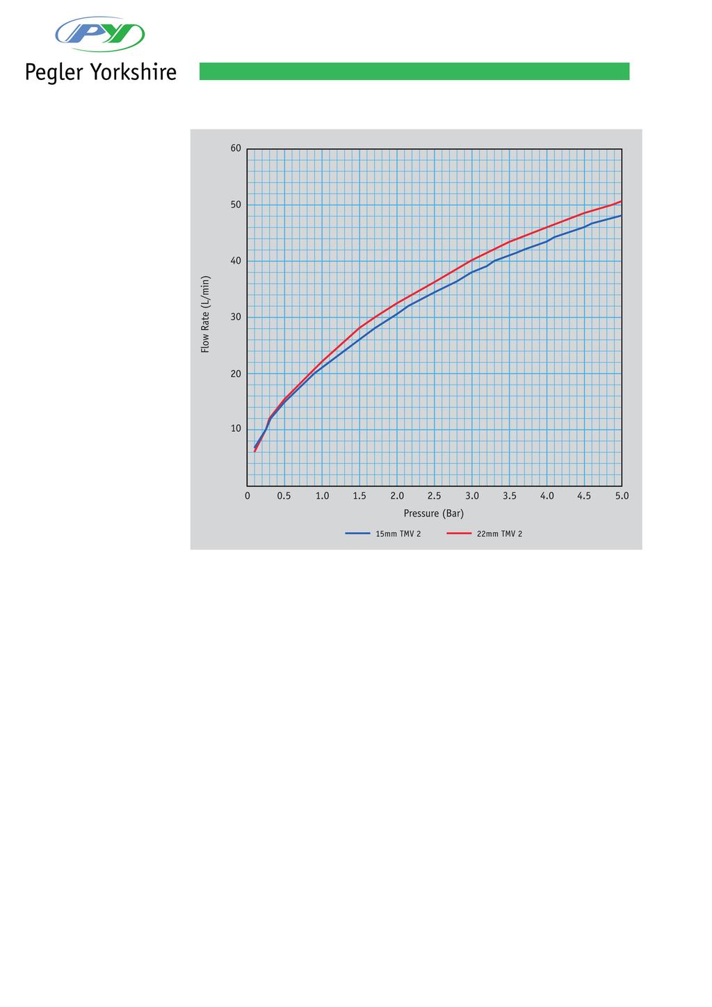
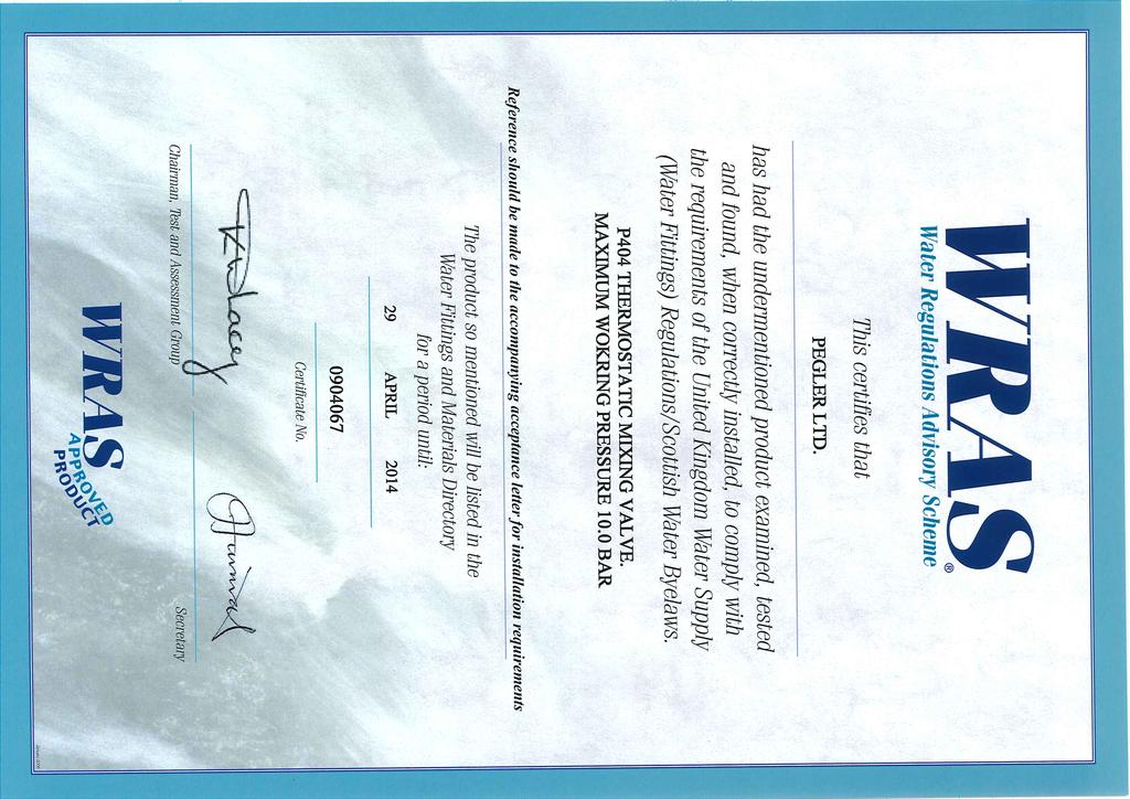
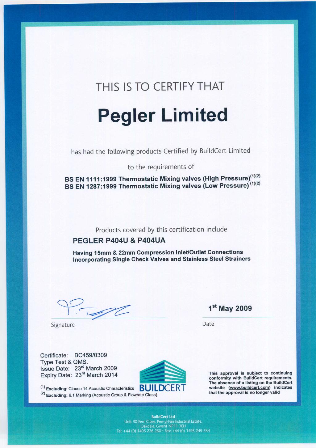
5 IMPORTANT INTRODUCTION NOTES The valves covered by these instructions have been tested and certified as being in compliance with BS EN 1111:1999 and BS EN 1287:1999. Valves operating outside the requirements of these standards are not covered by the TMV2 Scheme and are not guaranteed to operate as Type 2 valves. The installer should be aware of his duty of care and responsibility in ensuring that compliance with regulations is maintained. The valve is not guaranteed to function correctly to the TMV2 specification unless it is installed and used in accordance with these instructions. Regular servicing is essential to ensure continued safe operation of this thermostatic mixing valve. The recommended service interval is no greater than 12 months. This Prestex Model P404 in-line thermostatic mixing valve, available in 15mm and 22mm sizes, is intended to be fitted into applications where the reliable control of hot water temperature is necessary to prevent scalding. In the event of cold water supply failure, the product will shut off the hot water supply. Water Regulations The Prestex Model P404 mixing valve must be installed in accordance with the regulations of the local water company and the Water Supply (Water Fittings) Regulations Approvals This product is certified under the BuildCert TMV2 scheme and has been independently tested by an approved testing laboratory WRc-NSF and is a Water Regulations Advisory Scheme (WRAS) approved product and listed in the Water Fittings and Materials Directory. Installation Separate isolation valves must be installed on the hot and cold water inlet supplies. To ensure proper performance of the thermostatic mixing valve, the isolating valves should preferably be full bore and always be fully open during operation. The mixing valve is supplied with filter elements but it is advisable to additionally install Y-strainers on the hot and cold water supplies. The isolating valves and strainers should be installed as close as practicable to the location of the mixing valve and should always be in an accessible location. Before installation, the hot and cold water supply systems must be thoroughly flushed to remove any dirt/debris that may have accumulated. Failure to do so may adversely affect the performance of the mixing valve. CONDITIONS OF NORMAL USE Table 1 Operating Range High Pressure Low Pressure Maximum static pressure - bar Hot & cold flow pressure - bar 1.0 to to 1 Hot supply temperature - C 55 to to 65 Cold supply temperature - C Minimum hot inlet to mixed outlet temperature differential = 10 o C Note: Valves operating outside these conditions can not be guaranteed by the Scheme to operate as Type 2 valves. The highest flow rates will be achieved under balanced pressure conditions, but the pressure at the valve inlets must be within a ratio of 5:1 under flow conditions and the size and layout of pipework and fittings must take this into account.
6 FITTING Before installation, the system operating conditions of inlet pressures, hot water temperature and hot and cold water flow rates should be determined and confirmed to be within the expected conditions of normal use shown in the table below. BS1287 BSEN1111 Maximum static pressure (bar) Supply pressure hot and cold (bar) Hot supply C Cold supply C Maximum 25 Maximum 25 Mixed water temperature Maximum 46 Maximum 46 Valves must operate in either a high pressure setting or a low pressure setting. These valves are not capable of operation with, for instance hot water supply in one pressure range and cold water supply in the other pressure range. In these conditions it is necessary to either boost one pressure or reduce the other so that both supplies are within a common pressure range. If your water supply cannot meet these conditions then the valve cannot be guaranteed to operate as a Type 2 valve. Operating pressures above 5.0 Bar will require the installation of a pressure reducing valve. Correct location of the mixing valve is important to ensure that it is accessible for commissioning and servicing. The valve body is clearly marked with C for Cold and a blue indicator and H for Hot and a red indicator. The valve must be correctly connected to the respective supplies The use of sealing compounds must be avoided since they may intrude into the water supply and impair the valve performance. The valve must be so installed that it is readily accessible for commissioning and maintenance when being installed in accordance with TMV2. The valve must be installed with isolation valves on both the hot and cold water systems as close as possible to the valve; so as to allow the valve to be commissioned and tested correctly. The valve is supplied with integral strainers on the hot and cold water supplies therefore inline strainers should not be required. The valve is fitted with integral listed nonreturn valve cartridges which command the water supply, therefore the thermostatic valve is protected against cross-flow due to unbalanced line pressures as required by the Water Supply (Water Fittings) Regulations Assembly Procedure Unpack the main valve assembly, remove the three plastic protection caps and check that the bores are free of debris and the end sealing faces are clean. Unpack the two tailpieces and confirm they are complete with union nuts and compression nuts and olives. Locate the sealing gaskets, insert them into the union nuts against the faces of the tailpieces and screw the union nuts onto the valve until a tight seal has been made. Remove the compression nuts and olives from the tailpieces. Locate the inlet filter screens and insert them into the bore of the tailpieces up to the shoulder. Assemble the valve to the pipework and ensure the hot and cold water pipes have full penetration into the tailpiece. Tighten the compression nuts ensuring that the end of the pipe remains in contact with the filter element.
7 Exploded view of tailpiece assembly The Prestex Model P404UA mixing valve is optionally provided with angled assemblies in lieu of the tailpiece arrangement shown above. This allows the connections of the hot and cold water supplies to be parallel to the mixed water outlet for ease of piping layouts. The assemblies comprise an integral full bore ball valve and in-line strainer in an angled housing. When this arrangement is used, the requirements for isolation valves and Y-strainers previously mentioned are regarded as fulfilled. Exploded view of angled valve assembly ISOLATION VALVE HANDLE PRESSURE TAKE-OFF POINT PLUG SEAL HEADWORK SEAL FILTER MESH UNION NUT ISOLATION VALVE UNION SEAL APPLICATION The Prestex Model P404 thermostatic mixing valve has been independently tested by WRc-NSF against the requirements of BS EN 1287 (Low Pressure-LP) and BS EN 1111 (High Pressure-HP) and certified as complying with the requirements of the TMV2 Scheme and is suitable for use in the designations shown in the table below. Valves approved for designation for use HP only:- If a water supply is fed by gravity then the supply pressure should be verified to ensure the conditions of use are appropriate for the valve. Application Pressure Maximum set mixed water temperature Shower HP and LP 41 C Wash basin HP and LP 41 C Bidet HP and LP 38 C Bath (Tub)* HP 44 C The above temperatures are recommended by the Thermostatic Mixing Valve (manufacturers) Association as relevant settings for the varying applications shown. This is the maximum commissioning temperature but valves may exceed this by 2 C in use. The range of available temperature adjustment is 35 C to 48 C but 46 C is the maximum recommended mixed water temperature from a bath tap. The maximum temperature takes account of the allowable temperature tolerances inherent in thermostatic mixing valves and temperature losses in metal baths. 46 C is not a safe bathing temperature for adults or children. The British Burns Association recommends 37 C to 37.5 C as a comfortable bathing temperature for children. In premises covered by the Care Standards Act 2000, the maximum mixed water outlet temperature is 43 C.
8 COMMISSIONING The valve must be commissioned under normal site system conditions and after establishing supply conditions with the hot and cold water supplies open, leave the system running to allow temperatures and pressures to stabilise and be checked. Prior to commencing commissioning, the following checks should be carried out. The designation of the thermostatic mixing valve matches the application. The supply pressures and temperatures are within the operating range of the valve. Isolating valves and strainers are provided. If all these conditions are met, proceed to set the temperature as described below. The Prestex thermostatic mixing valve is supplied factory set at 43 C but the valve may be simply adjusted after installation. The mixed water temperature at the terminal fitting must never exceed 46 C When the valve has been installed with the correct conditions of use it is advised that the valve is subjected to exercise prior to the commissioning at the application temperature. Operate the valve from full cold to full hot at least three times. With the valve at the full cold position bring the valve to the correct application temperature by turning the spanner clockwise. If the valve overshoots this temperature, return the valve to the full cold condition, and reset it to the correct temperature +0-2 C. Do not set a valve on a lowered temperature as this will not provide consistent operation. When the valve is set to the required temperature for the application carry out 5 cold water isolation tests to further exercise the valve. Set the mixed water temperature to the required value. It is advisable to use a calibrated digital thermometer for checking the inlet and outlet temperatures. Remove the plastic protective cap on top of the valve with a suitable tool. Measure and record the temperature of the hot and cold water supplies at the inlets to the valve. Measure and record the temperature of the water discharging from the valve at the greatest draw-off flow rate. In the absence of other temperatures being specified those detailed in Table 2 are the desired settings Once the required mixed outlet temperature has been achieved, isolate the cold water supply and monitor and record the mixed water temperature including the maximum and final temperatures achieved. The mixed water temperature should never exceed 46 C. Re-fit the cap. using a close fitting spanner, reduce the mixed outlet temperature by turning clockwise. increase the mixed water outlet temperature by turning counterclockwise. Record all the equipment used during commissioning.
9 MAINTENANCE The Prestex Model P404 thermostatic mixing valve will provide satisfactory service and a high level of protection, provided it is maintained and subjected to In-Service Testing. Approximately 6-8 weeks after commissioning, the following tests should be undertaken. Temperature of the hot and cold water supplies - RECORD Temperature of the mixed water temperature at the greatest draw off flow rate RECORD If the mixed water temperature has significantly changed from that measured at installation (e.g. > 1 C), RECORD the change and before making any adjustments to the valve confirm that:- Strainer elements in the hot and cold water supplies are clean and undamaged. Non-return valves are clean and operating correctly. Isolation valves are operating correctly and are set in the fully open position. If the mixed water temperature is acceptable, the following additional observations should be made:- Isolate the cold water supply and RECORD the maximum temperature achieved. After 5 seconds, if water is still flowing RECORD the final temperature. If there is no significant change to the set outlet temperature (±2 C or less deviation from the original setting) and the fail safe shut-off is functioning, then the valve is working correctly and no further service work is required. If the maximum mixed water temperature exceeds the previous test results by more than 2 C then the need for service work on the valve is indicated. The equipment used in these In-Service Tests should be RECORDED and should preferably be the same as that used at installation. Note: If there is a residual flow during the commissioning or the annual verification (cold water supply isolation test) then this is acceptable providing the temperature of the water seeping from the valve is no more than 2 C above the designated maximum mixed water outlet temperature setting of the valve. Any higher temperatures should occur only briefly. Temperature readings should be taken at the normal flow rate after allowing the system to stabilise. The sensing part of the thermometer probe must be fully submerged in the water that is to be tested. Any TMV that has been adjusted or serviced must be re-commissioned and re-tested in accordance with the manufacturer s instructions. In the absence of any other instruction or guidance, it is recommended that In-Service Tests are carried out once every 12 months as a minimum. If the temperature is outside of the expected range it will be necessary to remove and clean the valve in accordance with the following instructions. TMV Cleaning and Servicing Instructions Most domestic water supplies contain calcium which will separate out when the water is heated in a system. The degree and speed of scaling may vary depending on factors such as water flow rates, system design, the hardness of the water and the temperature to which the water is heated. Deposits of scale may over time form in the valve, particularly at the hot inlet. The formation of the scale may adversely affect the performance of the valve which will be detected during the in-service testing. If this occurs it will be necessary to remove the valve for de-scaling and servicing.
10 TO SERVICE THE VALVE: Isolate the hot and cold supply. Remove the valve to a clean working area. Remove the protective cap. Unscrew the headwork of the valve. Carefully remove the element and valve assembly and put to one side. Remove the main spring and flow guide and carefully put to one side. Inspect the components for contamination or damage. Clean or replace as necessary Remove the two o rings Clean the valve body and headwork using a propriety de-scaler Thoroughly rinse the body and headwork in clean water. Carefully fit new o rings from the service kit taking care to ensure they are not damaged and are correctly located. Lubricate the o rings with the lubricant provided. Re-fit the flow guide and spring lubricating the flow guide around the greatest diameter with the lubricant provided Lubricate the shuttle valve with the lubricant provided Re-fit the shuttle valve and element assembly. Re-fit the headwork ensuring correct tightening Re-fit the assembled valve and perform the comissioning sequence. If after cleaning the valve, and replacing the o ring seals, the valve does not function correctly, it may be necessary to replace the thermal element. Exploded view of TMV assembly SPARES In order to ensure that the Prestex Model P404 thermostatic mixing valve continues to provide satisfactory service, only GENUINE Pegler spare parts must be used Spare part order Description code Protective cap complete with screw Hexagon key Service kit (15mm) (22mm) (15mm) (22mm) (15mm), (22mm) (15mm), (22mm) Tailpiece Strainer kit Angle valve strainer kit Sealing washer Wafer Strainer
11 Our brands: UK Sales Free Phone: Free Fax: Export Tel: +44 (0) Fax: +44 (0) Technical Help Free Phone: Free Fax: Brochure Hotline Free Phone: Free Fax: Also available from Pegler Yorkshire: LUXURY TAP SOLUTIONS Pegler Yorkshire Group Limited St. Catherine s Avenue, Doncaster, South Yorkshire, DN4 8DF, England. Tel: Fax: Registered in England Company No Registered Office: Haigh Park Road, Stourton, Leeds, West Yorkshire, LS10 1RT, England. All brand names and logo styles are registered trademarks. Maintaining a policy of continual product development, Pegler Yorkshire reserves the right to change specifications, design and materials of products listed in this leaflet without prior notice.
12
13
Installation Instructions and User Guide
 Installation Instructions and User Guide 15mm & 22mm In-Line Thermostatic Mixing Valve-TMV2 Model P404 It is important that these guidance notes are read and fully understood prior to product installation
Installation Instructions and User Guide
 Installation Instructions and User Guide 15mm & 22mm In-Line Thermostatic Mixing Valve-TMV3 Model P402 It is important that these guidance notes are read and fully understood prior to product installation
PEG402, PEG402UA & PEG402UAX TMV3 / TMV2 Combined
 Domestic Valve Solutions Installation Instructions and User Guide 15mm & 22mm In-Line Thermostatic Mixing Valve PEG402, PEG402UA & PEG402UAX TMV3 / TMV2 Combined It is important that these guidance notes
Installation Instructions and User Guide 15mm & 22mm Thermostatic Mixing Valve
 Installation Instructions and User Guide 15mm & 22mm Thermostatic Mixing Valve TMV3 / TMV2 Combined Valve C85079 C85081 C85080 C85082 It is important that these guidance notes are read and fully understood
THERMOSTATIC MIXING VALVES
 THERMOSTATIC MIXING VALVES D1088 & D1089 INTRODUCTION Are self-acting Thermostatic Mixing Valves designed to blend hot and cold water, to ensure a constant, safe outlet temperature and prevent scalding.
Installation Guide - C01202 & C01203 Thermostatic Mixing Valve TMV2
 The following information is required for use when the Saracen range of thermostatic mixing valves is used in a TMV2 Applications under the requirements of BS EN 1111: 1999 Sanitary tap ware Thermostatic
Intamix Thermostatic Mixing Valve
 Intamix Thermostatic Mixing Valve TMV2 & TMV3 Installation Guide Intatec Ltd Airfield Industrial Estate Hixon Staffordshire ST18 0PF In this procedure document we have endeavoured to make the information
PRV4 PT Pressure Reducing Valve
 For latest prices and delivery to your door visit MyTub Ltd - 0845 303 8383 - www.mytub.co.uk - info@mytub.co.uk PRV4 PT Pressure Reducing Valve Pressure Reducing Valve FxF ISO228 Parallel Thread GENERAL
Twin & Triple Control Concealed Thermostatic Shower Valve
 Twin & Triple Control Concealed Thermostatic Shower Valve Installation & Operating Guide Please leave this installation & user guide with the end user CONTENTS: 1. Introduction & Safety 1 2. Dimensions
TEMPERATURE STABILISED THERMOSTATIC SHOWER PANEL
 Product Support Guarantee This product is guaranteed against faulty materials and workmanship for 12 months from date of purchase. For the guarantee to be valid, the unit must be installed by a competent
Deluge Optimo Shower valve and kit 10032CP
 Deluge Optimo Shower valve and kit 10032CP Installation, Operation and Maintenance Please leave these instructions with the user Intatec Limited Airfield Industrial Estate, Hixon, Staffordshire, ST18 0PF
Self-help Temperature Adjustment
 Self-help Temperature Adjustment The Shower Valve temperature is pre-set to 42 C, but on certain installations the temperature may need to be adjusted. Note: The hot water supply must be above 60 C. Turn
HORNE 20 THERMOSTATIC MIXING VALVE TYPE H-2003
 PO Box 7, Rankine Street Johnstone, Renfrewshire Scotland. PA5 8BD Tel: 01505 321 455 Fax: 01505 336 287 Email: technical@horne.co.uk Web: www.horne.co.uk HORNE 20 THERMOSTATIC MIXING VALVE TYPE H-2003
Scald Protection Three-Way Thermostatic Mixing Valve
 CALEFFI www.caleffi.com 383.04 Scald Protection Three-Way Thermostatic Mixing Valve Copyright 00 Caleffi 3 Series Installation, commissioning and servicing instructions Function Scald Protection Three-Way
INSTALLATION, OPERATING AND MAINTENANCE GUIDE FOR EXPOSED AND CONCEALED MODELS MODERN, TRADITIONAL AND MINIMALISTIC
 INTAFLO SEQUENTIAL THERMOSTATIC SHOWER VALVE S INSTALLATION, OPERATING AND MAINTENANCE GUIDE FOR EXPOSED AND CONCEALED MODELS MODERN, TRADITIONAL AND MINIMALISTIC PLEASE LEAVE THESE INSTRUCTIONS WITH THE
Cast iron swing check valve. BS EN 12334:2001 PN16
 Cast iron swing check valve. BS EN 12334:2001 PN16 V914 Size Pattern No. Pack 1 Qty Pack 2 Qty Code Barcode Price ( ) ex VAT 65mm V914 1 0 15378 5022050079664 223.32 80mm V914 1 0 15379 5022050079824 247.60
Installation, Operating and Maintenance Instructions. V914 Cast Iron Flanged Swing Check Valve V914
 Installation, Operating and Maintenance Instructions V914 Cast Iron Flanged Swing Check Valve V914 THE PRESSURE EQUIPMENT DIRECTIVE 97/23/EC and CE MARKING The Pressure Equipment Regulations 1999 (SI 1999/2001)
Installation, commissioning and servicing instructions
 www.reece.com.au Tempering valve 38550.08 5213 series Installation, commissioning and servicing instructions The tempering valve is used to regulate the set temperature of mixed hot and cold water even
SEQUENTIAL SHOWER VALVE INSTRUCTION MANUAL PLEASE LEAVE THIS MANUAL WITH THE END USER
 SEQUENTIAL SHOWER VALVE INSTRUCTION MANUAL PLEASE LEAVE THIS MANUAL WITH THE END USER CONTENTS 1. INTRODUCTION & SAFETY 1 2. DIMENSIONS 2 3. TECHNICAL DATA 3 4. OPERATION 4 5. COMPONENTS 5 6. SITE INSTALLATION
Scald Protection 3-Way Thermostatic Mixing Valve
 383.06 www.caleffi.com Scald Protection 3-Way Thermostatic Mixing Valve Copyright 06 Caleffi 3 Series Installation, commissioning and servicing instructions Function Scald Protection Three-Way Thermostatic
bathrooms.com Concentric Thermostatic Shower Mixers Cleaning and Care Installation Manual Contents
 bathrooms.com Concentric Thermostatic Shower Mixers Contents Page 3 - General Information & Safety Page 4 - Installation Page 5 - Concentric Valve Set-up Page 6 - Exposed fitting of Concentric Mixer Valves
Tempering valve for solar and instantaneous applications Installation, commissioning and servicing instructions 2522HP series
 www.reece.com.au 28255.01 Tempering valve for solar and instantaneous applications 2522HP series Installation, commissioning and servicing instructions The tempering valve is used to regulate the set temperature
Thermostatic Mixing Valves 61022CPB & 61028CPB Intamix Pro V
 Thermostatic Mixing Valves 61022CPB & 61028CPB Intamix Pro V Installation and Maintenance Instructions 2 1 MIN MAX 7 In this procedure document we have endeavoured to make the information as accurate as
SMV-001 Thermostatic Shower Mixer Valve Installation Instructions & Adjustment Settings
 SMV-001 Thermostatic Shower Mixer Valve Installation Instructions & Adjustment Settings 38 READ ALL INSTRUCTIONS CAREFULLY BEFORE INSTALLATION. LEAVE THIS BOOKLET WITH THE END USER FOR FUTURE REFERENCE
Installation, commissioning and servicing instructions
 38512.08 Tempering valve www.caleffi.com 5213 series Copyright 2018 Caleffi Installation, commissioning and servicing instructions The tempering valve is used to regulate the set temperature of mixed hot
DB 61 Dolphin TMV3 Integrated Thermostatic Mixing Valve
 INSTALLATION AND MAINTENANCE GUIDE DB 61 Dolphin TMV3 Integrated Thermostatic Mixing Valve Saving water, saving power, promoting hygiene Important: Read carefully before installing product DOLPHIN Revision
TMV3 Requirements IMPORTANT Installer:
 TMV3 Requirements IMPORTANT Installer: This Manual is the property of the customer and must be retained with the product for maintenance and operational purposes. 1 1173533-W2-C General The information
Issue date: July 2012 Issue 1
 Guide to commissioning, in-service inspection, in-service test and frequency of testing Thermostatic Mixing Valves (TMV) for use in health and social care establishments as Type 3 valves (TMV3 approved).
Ductile iron gate valve PN16. BS EN 1171:2002 PN16
 gate valve PN16. BS EN 1171:2002 PN16 V950 Gate valve Size Pattern No. Pack 1 Qty Pack 2 Qty Code Barcode Price ( ) ex VAT DN50 V950 1 0 15510 5022050210906 233.60 DN65 V950 1 0 15511 5022050211262 233.60
 IN-SERVICE TESTING The purpose of in-service testing is to regularly monitor the thermal performance of the thermostatic mixing valve. Deterioration in performance can indicate the need for service work
Issue date: April 2017
 NSF Guide to commissioning, inservice testing and frequency of testing of Thermostatic Mixing Valves (TMV) for use in Healthcare premises as Type 3 valves (TMV3 approved). Issue date: April 2017 1. Introduction
1. Introduction. The Easy Guide to TMV3 Approval
 THE EASY GUIDE TO TMV3 APPROVAL 1. Introduction NSF approves two categories of Thermostatic Mixing Valves; TMV2 and TMV3. The different valve types are explained in Table 1. TMV3 approval is for thermostatic
Installation, commissioning and servicing instructions. General
 F. istr. 38650_5213 9-07-2007 14:04 Pagina 1 CALEFFI www.caleffi.com 38650 Thermostatic Mixing Valves 5213TM series Installation, commissioning and servicing instructions General The Caleffi 5213TM series
Bar valve with fixed shower head Installation guide
 Midas Plus Mono Bar valve with fixed shower head Installation guide Midas Plus Mono Midas Plus Mono Components Literature not shown Important information Introduction The Midas Plus Mono product is an
Brass full bore gate valve with lockshield. Compression ends to EN 1254/2, PN16
 Brass full bore gate valve with lockshield. Compression ends to EN 1254/2, PN16 63LS Gate valve Size Pattern No. Pack 1 Qty Pack 2 Qty Code Barcode Price ( ) ex VAT 15mm 63LS 10 0 506037 5013866016103
All DZR stopvalve (BS1010). copper x copper. Gunmetal body. All parts in contact with water are made from material resistant to dezincification.
. copper x copper. Gunmetal body. All parts in contact with water are made from material resistant to dezincification.") All DZR stopvalve (BS1010). copper x copper. Gunmetal body. All parts in contact with water are made from material resistant to dezincification. K551DZR Size Pattern No. Pack 1 Qty Pack 2 Qty Code Barcode
All DZR stopvalve (BS1010). copper x copper. Gunmetal body. All parts in contact with water are made from material resistant to dezincification. K551DZR Size Pattern No. Pack 1 Qty Pack 2 Qty Code Barcode
Atmos Low Pressure Thermostatic Bar Mixer Valve
 INSTALLATION & OPERATING INSTRUCTIONS Atmos Low Pressure Thermostatic Bar Mixer Valve Customer Care - 0845 505 2211 INTRODUCTION This book contains all the necessary fitting and operating instructions
INSTALLATION INSTRUCTIONS 1/2 THERMOSTATIC VALVE AND TRIM
 INSTALLATION INSTRUCTIONS 1/2 THERMOSTATIC VALVE AND TRIM Valve Model No's: 1-741, 1-742, 1-743, 1-744 1-741 1-742 1-743 1-744 2001 CARNEGIE AVE, SANTA ANA CA 92705 (949) 417-5207 WWW.NEWPORTBRASS.COM
3.5 litr es per INSTALLATION INSTRUCTIONS. Avon 21 Self-closing taps (Push button) B0992AA Self-closing basin pillar tap
 B0992AA Self-closing basin pillar tap") Avon 21 Self-closing taps (Push button) INSTALLATION INSTRUCTIONS B0992AA Self-closing basin pillar tap WaterMark AS/NZS 3718 WMK 25822 SAI Global The more stars the more water efficient WATER RATING www.waterrating.gov.au
Avon 21 Self-closing taps (Push button) INSTALLATION INSTRUCTIONS B0992AA Self-closing basin pillar tap WaterMark AS/NZS 3718 WMK 25822 SAI Global The more stars the more water efficient WATER RATING www.waterrating.gov.au
Horne Engineering Ltd
 Horne Engineering Ltd Po Box 7, Rankine Street Johnstone, Renfrewshire Scotland, PA5 8BD Tel: 01505 321455 Fax: 01505 336287 Email: technical@horne.co.uk Web: www.horne.co.uk HORNE T105A/106A/107A/108A
Engineering Data Sheet
 Page 1 of 6 CE MARKING AND THE PRESSURE EQUIPMENT DIRECTIVE 97/23/EC Valves must be installed into a well designed system and it is recommended that the system be inspected in accordance with the appropriate
Options Concentric Petite
 Options Concentric Petite Thermostatic Mixer Valve with Exposed and Concealed Fitting Options Fitting Instructions IMPORTANT This Step-by-Step guide should be retained after installation. 1. INTRODUCTION
Installation, commissioning and servicing instructions
 488.03 www.reece.com.au Pressure reducing s Installation, commissioning and servicing instructions Function Pressure reducing s are installed in residential water systems to reduce and stabilise inlet
RS(H)10,15 USER MANUAL. Read the complete manual before installing and using the regulator.
10,15 USER MANUAL. Read the complete manual before installing and using the regulator.") RS(H)10,15 USER MANUAL Read the complete manual before installing and using the regulator. WARNING INCORRECT OR IMPROPER USE OF THIS PRODUCT CAN CAUSE SERIOUS PERSONAL INJURY AND PROPERTY DAMAGE. Due to
RS(H)10,15 USER MANUAL Read the complete manual before installing and using the regulator. WARNING INCORRECT OR IMPROPER USE OF THIS PRODUCT CAN CAUSE SERIOUS PERSONAL INJURY AND PROPERTY DAMAGE. Due to
Thermostatic Concentric Mixer Valve. with Exposed and Concealed Fitting Options. Fitting Instructions
 Atmos Fusion Thermostatic Concentric Mixer Valve with Exposed and Concealed Fitting Options Fitting Instructions IMPORTANT This Step-by-Step guide should be retained after installation. 1. INTRODUCTION
DS05C,D,G Dial Set Pressure Regulating Valves
 DS05C,D,G Dial Set Pressure Regulating Valves APPLICATION The Honeywell DS05C,D,G Dial Set Pressure Regulating Valve is a high quality pressure regulating valve that maintains a constant outlet pressure
PRS(TC)4,8 USER MANUAL. Read the complete manual before installing and using the regulator.
4,8 USER MANUAL. Read the complete manual before installing and using the regulator.") PRS(TC)4,8 USER MANUAL Read the complete manual before installing and using the regulator. WARNING INCORRECT OR IMPROPER USE OF THIS PRODUCT CAN CAUSE SERIOUS PERSONAL INJURY AND PROPERTY DAMAGE. Due to
PRS(TC)4,8 USER MANUAL Read the complete manual before installing and using the regulator. WARNING INCORRECT OR IMPROPER USE OF THIS PRODUCT CAN CAUSE SERIOUS PERSONAL INJURY AND PROPERTY DAMAGE. Due to
PRODUCT MANUAL IMPORTANT
 PRODUCT MANUAL IMPORTANT Installer: This Manual is the property of the customer and must be retained with the product for maintenance and operational purposes. 1 Contents Safety : Warnings...3 Advice...3
Forged brass full way gate valve with lockshield. BS 5154 PN20 Series B.
 Forged brass full way gate valve with lockshield. BS 5154 PN20 Series B. 1068 LS Size Pattern No. Pack 1 Qty Pack 2 Qty Code Barcode Price ( ) ex VAT 1/2" 1068 LS 10 0 203067 5013866015038 20.60 3/4" 1068
PRESSURE TEST PUMP OPERATING & MAINTENANCE INSTRUCTIONS. Model No: PTP100. Part No: GC01/09
 PRESSURE TEST PUMP Model No: PTP00 Part No: 06020 OPERATING & MAINTENANCE INSTRUCTIONS GC0/09 INTRODUCTION Thank you for purchasing this CLARKE Pressure Testing Pump. Before attempting to use the product,
TECHNICAL INSTRUCTIONS
 TECHNICAL INSTRUCTIONS Hydroguard Series 410 Valves Model 5 and Model 8 Form TI410-5 v3 DESCRIPTION The Series 410 Hydroguard is a pressure compensating mixer which delivers a predetermined water temperature,
Thermostatic Concentric Mixer Valves
 INSTALLATION & OPERATING INSTRUCTIONS Thermostatic Concentric Mixer Valves Customer Care - 0845 505 2211 INTRODUCTION This book contains all the necessary fitting and operating instructions for your thermostatic
book : t95575.fm Seite 1 Mittwoch, September 20, :10 AM. Avensys. Exposed Single Lever Mixer
 955751.book : t95575.fm Seite 1 Mittwoch, September 20, 2000 10:10 AM Avensys Exposed Single Lever Mixer 33 389 33 396 Installation Instructions and Operating Guide Please leave this document with the
15/3 THERMOSTATIC MIXING VALVE PRODUCT MANUAL IMPORTANT
 15/3 THERMOSTATIC MIXING VALVE PRODUCT MANUAL IMPORTANT Installer: This Manual is the property of the customer and must be retained with the product for maintenance and operational purposes. 1 INDEX Page
LRS(H)4 USER MANUAL. Read the complete manual before installing and using the regulator.
4 USER MANUAL. Read the complete manual before installing and using the regulator.") LRS(H)4 USER MANUAL Read the complete manual before installing and using the regulator. WARNING INCORRECT OR IMPROPER USE OF THIS PRODUCT CAN CAUSE SERIOUS PERSONAL INJURY AND PROPERTY DAMAGE. Due to the
LRS(H)4 USER MANUAL Read the complete manual before installing and using the regulator. WARNING INCORRECT OR IMPROPER USE OF THIS PRODUCT CAN CAUSE SERIOUS PERSONAL INJURY AND PROPERTY DAMAGE. Due to the
Atmos Zone. Thermostatic Concealed Concentric Mixer Valve with Fixed Head. Fitting Instructions
 Atmos Zone Thermostatic Concealed Concentric Mixer Valve with Fixed Head Fitting Instructions IMPORTANT! This Step-by-Step guide should be retained after installation. 1. INTRODUCTION This booklet contains
Instruction Sheet. SUPERSEDES: New EFFECTIVE: August 1, 2013
 Instruction Sheet 102-492 5123-WH-N Lead Free (.25% Pb) Mixing Valve SUPERSEDES: New EFFECTIVE: August 1, 2013 Plant I.D. 001-4206 WARNING: Water temperatures above 120 F can cause serious injury. Mixing
MANUAL FOR INSTALLATION, COMMISSIONING AND MAINTENANCE FOR
 MANUAL FOR INSTALLATION, COMMISSIONING AND MAINTENANCE FOR RMC TM THERMOMIX TM 300 25MM THERMOSTATIC MIXING VALVE FOR USE IN AUSTRALIA AND NEW ZEALAND CONTENTS SECTION PAGE NO. 1. INTRODUCTION 2 2. WARRANTY
HORNE T109A/306A/307A THERMOSTATIC SHOWER VALVE FOR SURFACE MOUNTING WITH TIMED FLOW CONTROL INSTALLATION, OPERATION & MAINTENANCE INSTRUCTIONS
 Horne Engineering Ltd PO Box 7, Rankine Street Johnstone, PA5 8BD Tel: +44 (0)1505 321455 Fax: +44 (0)1505 336287 Email: Technical@horne.co.uk Web: www.horne.co.uk HORNE T109A/306A/307A THERMOSTATI SHOWER
D05 Pressure Regulating Valves
 D05 Pressure Regulating Valves FEATURES PRODUCT DATA Noncorroding unitized cartridge contains all working parts and is easily replaceable. Includes built-in strainer and thermal bypass. Balanced seat construction
National Health Service Model engineering Specification
 National Health Service Model engineering Specification D 08 Thermostatic mixing valves (Healthcare premises) Issue date: Issue 4 Page 2 Contents Page No 0. Introduction 4 1. Scope 4 2. Definitions 6 3.
Instruction Manual - Diaframless TM Ejector Chlorine, Sulfur Dioxide and Ammonia
 Instruction Manual - Diaframless TM Ejector Chlorine, Sulfur Dioxide and Ammonia - 1-122.6010.6 These instructions describe the installation, operation and maintenance of the subject equipment. Failure
215 and 222 Series PRODUCT MANUAL
 215 and 222 Series PRODUCT MANUAL IMPORTANT Installer: This Manual is the property of the customer and must be retained with the product for maintenance and operational purposes. 1 Contents Introduction
Atmos Fusion. Thermostatic Concentric Mixer Valve with Riser Rail. Fitting Instructions
 Atmos Fusion Thermostatic Concentric Mixer Valve with Riser Rail Fitting Instructions IMPORTANT This Step-by-Step guide should be retained after installation. 1. INTRODUCTION This booklet contains all
Installation, operation & maintenance manual - original version
 Installation, operation & maintenance manual - original version AVK gate valves for water and wastewater Series 01, 02, 06, 12, 15, 18, 20, 26, 32, 33, 36, 38, 50, 55 and 636 COPYRIGHT AVK GROUP A/S 2018
PRODUCT MANUAL IMPORTANT
 PRODUCT MANUAL IMPORTANT Installer: This Manual is the property of the customer and must be retained with the product for maintenance and operational purposes. 1 INDEX Page SAFETY WARNINGS 3 ADVICE 3 INTRODUCTION
THE HF-300 SERIES. Operating and Service Manual. Series includes all variants of HF-300/301
 THE HF-300 SERIES Operating and Service Manual Series includes all variants of HF-300/301 Issue A July 2015 1 TABLE OF CONTENTS 1. Description... 3 2. Installation... 3 3. Operation... 4 3.1. Spring Loaded...
INSTALLATION, COMMISSIONING AND MAINTENANCE INSTRUCTIONS
 TM Australian Standard WaterMark ATS S5200.012 4032.1 Lic No. 20137 INSTALLATION, COMMISSIONING AND MAINTENANCE INSTRUCTIONS DR DR 15mm & 20mm THERMOSTATIC MIXING VALVE FOR FOR USE USE IN IN AUSTRALIA
WORCESTER GREENSTORE. Indirect Unvented Cylinder with Solar Coil FOR USE WITH WORCESTER GREENSTORE SYSTEM HEATPUMP ONLY GB/IE
 WORCESTER GREENSTORE Indirect Unvented Cylinder with Solar Coil FOR USE WITH WORCESTER GREENSTORE SYSTEM HEATPUMP ONLY GB/IE WORCESTER GREENSTORE 180 CYLINDER SOLAR COMPATIBLE WORCESTER GREENSTORE 280
KTM 50 (DN ) Installation, maintenance and operating instructions
 Installation, maintenance and operating instructions") 52 762-306 09.2014 KTM 50 (DN 100-200) Installation, maintenance and operating instructions General High-performing and compact, these pressure-independent control valves for variable flow heating and
52 762-306 09.2014 KTM 50 (DN 100-200) Installation, maintenance and operating instructions General High-performing and compact, these pressure-independent control valves for variable flow heating and
PRESSURISED PAINT CONTAINER
 PRESSURISED PAINT CONTAINER MODEL NO: CPP2B PART NO: 3082115 OPERATION & MAINTENANCE INSTRUCTIONS GC0913 INTRODUCTION Thank you for purchasing this CLARKE Pressurised Paint Container. Before attempting
1805 Series Relief Valves
 Instruction Manual Form 1211 1805 Series October 2011 1805 Series Relief Valves! WARNING Failure to follow these instructions or to properly install and maintain this equipment could result in an explosion
DS06D,G Dial Set Pressure Regulating Valve
 DS06D,G Dial Set Pressure Regulating Valve PRODUCT DATA FEATURES APPLICATION Built-in, factory-calibrated outlet pressure adjustment dial. Noncorroding unitized cartridge contains all working parts and
MODEL 200 KNIFE GATE VALVES INSTALLATION & MAINTENANCE MANUAL
 MODEL 200 KNIFE GATE VALVES INSTALLATION & MAINTENANCE MANUAL Index 1. List of components / General arrangement 2. Description 3. Handling 4. Installation 5. Actuators / Operation 6. Maintenance a. Changing
Latvin Luxury Shower Panel. Telephone Product Specification. ~ Minimum Working Pressure 1.0 bar ~ Maximum Working Pressure 3.
 Product Specification ~ Minimum Working Pressure 1.0 bar ~ Maximum Working Pressure 3.0 bar Latvin Luxury Shower Panel ~ Fixing Centres 150mm +/- 10mm ~ Outlet size 1/2" Bottom Outlet Always maintain a
Instruction Manual. Standard Surge Eliminator. Standard X. Flushable X - X
 Standard Surge Eliminator Standard 104052 - X Flushable 104053 - X - X Page 2 of 16 Issue: 2.3 Index Section 1.1 General Description 1.2 Operating Principle 1.3 Specification 1.4 Fitting Selection - Standard
SCA Series Inverted Bucket Steam Traps
 0770050/5 IM-P077-06 ST Issue 5 SCA Series Inverted Bucket Steam Traps Installation and Maintenance Instructions 1. General safety information 2. General product information 3. Installation 4. Commissioning
CARTRIDGE FILTERS TECHNICAL MANUAL MT 080. Installation, commissioning and maintenance instructions. 08/02 Edition
 CARTRIDGE FILTERS TECHNICAL MANUAL MT 080 Installation, commissioning and maintenance instructions 08/02 Edition 1 2 CONTENTS 1.0 PAGE INTRODUCTION 1.1 MAIN FEATURES 1.2 OPERATION 1.3 CLOSING OF HEAD WITH
553 Series.
 38467.03 www.caleffi.com Pre-adjustable filling units Copyright 01 Caleffi 3 Series Function The automatic filling valve is a device consisting of a pressure reducing valve with compensating seat, visual
FILTER REGULATORS MODEL NO: CAT155 & CAT156 FITTING & MAINTENANCE INSTRUCTIONS PART NO: & ORIGINAL INSTRUCTIONS
 FILTER REGULATORS MODEL NO: CAT155 & CAT156 PART NO: 3120169 & 3120170 FITTING & MAINTENANCE INSTRUCTIONS ORIGINAL INSTRUCTIONS GC0117 INTRODUCTION Thank you for purchasing this CLARKE Filter/Regulator.
These instructions must be left with the user.
 MIRA MOTO, MIRA PACE, MIRA MINILITE, AND MIRA MINIDUO ( including Eco models) THERMOSTATIC MIXERS INSTALLATION & USER GUIDE These instructions must be left with the user. 1 CONTENTS Introduction 2 Guarantee
Model: 720-UL INSTALLATION OPERATION MAINTENANCE. Bermad Pressure Reducing Valve IOM. Model: FP -720-UL Sizes: 2"-12" BERMAD. Application Engineering
 Bermad Pressure Reducing Valve Model: 720-UL INSTALLATION OPERATION MAINTENANCE Application Engineering BERMAD 1. Safety First BERMAD believes that the safety of personnel working with and around our equipment
D05T Compact Design Pressure Regulating Valves
 D05T Compact Design Pressure Regulating Valves FEATURES PRODUCT DATA Non-corroding unitized cartridge contains all working parts and is easily replaceable. Includes built-in strainer and thermal bypass.
INSTALLATION INSTRUCTIONS
 Part No. IS275 Rev A- 09584-09584 TM HeatGuard INSTALLATION INSTRUCTIONS Certified Product Australian Standard AS4032.2 Lic. No. 1593 SAI-Global CONTENTS Choosing the correct model......... 3 How to install
TITAN FLOW CONTROL, INC.
 PREFACE: This manual contains information concerning the installation, operation, and maintenance of Titan Flow Control (Titan FCI) WYE Type Strainers. To ensure efficient and safe operation of Titan FCI
Installation, commissioning and servicing instructions
 48323 www.caleffi.com Pre-adjustable pressure reducing valve with self-contained cartridge Copyright 2015 Caleffi 5350..H AUS series Installation, commissioning and servicing instructions Function Pressure
AQUABLEND MM THERMOSTATIC MIXING VALVE
 AQUABLEND 2500 25MM THERMOSTATIC MIXING VALVE For use in Australia Part No. IS127 I00045_Aug _16 Call 1300 369 273 Enware Australia Pty Limited 9 Endeavour Rd Caringbah NSW 2229 Australia Ph: +61 2 8556
Rada-Presto TF2020 and TF2020S
 Rada-Presto TF2020 and TF2020S PRODUCT MANUAL IMPORTANT Installer: This Manual is the property of the customer and must be retained with the product for maintenance and operational purposes. 1 INDEX Page
KTM OM-2 SPLIT BODY FLOATING BALL VALVES INSTALLATION AND MAINTENANCE INSTRUCTIONS
 Before installation these instructions must be fully read and understood SECTION 1 - STORAGE 1.1 Preparation and preservation for storage All valves should be properly packed in order to protect the parts
Flowmeter. Original operating manual DFM
 Flowmeter Original operating manual Series DFM 165 350 Version BA-2016.08.09 EN Print-No. 300 458 TR MA DE Rev002 ASV Stübbe GmbH & Co. KG Hollwieser Straße 5 32602 Vlotho Germany Phone: +49 (0) 5733-799-0
Speed control assembly model A-1
 Pressure Regulation 533a 1. DESCRIPTION The Viking Speed Control Assembly provides adjustment of the opening speed of Viking Deluge Valves, and adjustment of both the opening and closing speed of Viking
These instructions must be left with the user
 Mira Moto, Mira Pace, Mira Minilite and Mira Miniduo ( including Eco Models) Thermostatic Mixers For SPARES, ADVICE or REPAIRS Please call us on 0844 571 5000 (UK Only) These instructions must be left
TD45 Thermodynamic Steam Trap Installation and Maintenance Instructions
 0685255/1 IM-P068-47 ST Issue 1 TD45 Thermodynamic Steam Trap Installation and Maintenance Instructions 1 General safety information 2 General product information 3 Installation 4 Commissioning 5 Operation
TITAN FLOW CONTROL, INC.
 PREFACE: This manual contains information concerning the installation, operation, and maintenance of Titan Flow Control (Titan FCI) Simplex Basket Strainers. To ensure efficient and safe operation of Titan
V12 THERMOSTATIC SHOWER VALVE PRODUCT MANUAL
 V12 THERMOSTATIC SHOWER VALVE PRODUCT MANUAL IMPORTANT Installer: This Manual is the property of the customer and must be retained with the product for maintenance and operational purposes. 1 1145094-W2-A
BASIN AND WALL MIXER INSTALLATION INSTRUCTIONS
 BASIN AND WALL MIXER INSTALLATION INSTRUCTIONS IMPORTANT INFORMATION IMPORTANT All tapware and showers to be installed by a licensed plumber and to Australian Standards. Fit tempering and pressure reduction
THE MF-400 SERIES. Operating and Service Manual. Series includes all variants of MF-400/401
 THE MF-400 SERIES Operating and Service Manual Series includes all variants of MF-400/401 Issue A October 2013 1 TABLE OF CONTENTS 1. Description... 3 2. Installation... 3 3. Operation... 4 4. Special
Installation, commissioning and servicing instructions
 3838.10 www.caleffi.com Inclined pressure reducing s opyright 2018 aleffi 33 series Installation, commissioning and servicing instructions Function Pressure reducing s are installed in residential water
Pipe threads for tubes and fittings where pressure-tight joints are not made on the threads. (requires PTFE sealing tape or liquid sealant).
.") Fittings for CO 2 Pipe Threads Pipe thread references quoted in this catalogue conform with the requirements specified in the latest issue and amendments of the following ISO Standards: ISO 7-1 (BS21)
Fittings for CO 2 Pipe Threads Pipe thread references quoted in this catalogue conform with the requirements specified in the latest issue and amendments of the following ISO Standards: ISO 7-1 (BS21)
Dri-Line Mk2 Spirax-Monnier Compressed Air Drain Trap
 0509950/2 IM-P050-21 CH Issue 2 Dri-Line Mk2 Spirax-Monnier Compressed Air Drain Trap Installation and Maintenance Instructions 1. Safety information 2. General product information 3. Installation and