Seattle City Light Construction Management
|
|
|
- Robyn Watson
- 5 years ago
- Views:
Transcription

1 Seattle City Light Construction Management Submittal Transmittal & Response Shaded areas are for SCL use only Submittal Number: Date: 10/26/2015 (Contractor: give each submittal transmittal a consecutive number beginning with 001. Resubmittals will be identified numerically, e.g., ) Note: One form, in MS Word, shall be filled out for each submittal item. The only exception will be if multiple items from the same supplier are submitted as a package for the same scheduled work. Form can be modified to add lines as needed.) Contract Name: T-117 Adjacent Street Cleanup PW #: Contractor: Gary Merlino Construction Co. Sub item # The Contractor submits the following noted attachments to Engineer for review and response: Spec Sec. # DESCRIPTION SCL Response Shoring Plan SI Resubmittal Supplemental Submittal Submitted by: Patrick Hafferty Project Manager Printed Name Printed Title Phone # The Engineer has reviewed the above noted documents and responded as noted above, under SCL Response. Key: NE = NO EXCEPTIONS TAKEN MC = MAKE CORRECTIONS NOTED: No resubmittal required, but corrections noted are required SI RR RJ I = SUBMIT SPECIFIED ITEM: Resubmittal required rejected, see comments below = REVISE AND RESUBMIT: Resubmittal required rejected, see comments below = REJECTED see comments below = INFORMATION ONLY Note: Review is only for conformance with the general design concept of the Project and does not extend to consideration of structural integrity, safety, detailed compliance with Contract requirements and any other obligation of the Contractor. Any action shown is subject to the requirements of the construction Contract. Contractor is responsible for confirming and correlating all dimensions; fabricating and construction techniques; coordinating its work with that of all other trades; and the satisfactory performance of its entire work in strict accordance with the construction Contract. The review is undertaken solely to satisfy Engineer s obligations and does not relieve Contractor from its obligation fully to perform all Contract requirements, nor shall such review give rise to any right of action or suit in favor of Contractor or third persons, against the Owner. Comments or actions may not be complete, once non-compliance is documented, the review may be discontinued and the submittal rejected. Engineer s Comments and Sign-off: # (key to above) 1 Comment If the shoring system will be used in a non-trench capacity, submit calculations performed by a structural engineer licensed in the State of Washington to demonstrate that the system will adequately resist sliding and overturning forces. Eric Pilcher Engineer of Record 10/27/2015 Signature Printed Name & Title Date See Attached Engineer s Comments See Mark-Up of Submittal Documents See Other Attachments
2 Cc: Project File Form (Rev. 03/15)
3 In response to SCL submittal 102 response dated 10/23/15, GMCC provides the following supplemental information. Specification section (1) requires protective systems used in excavations over 20ft in depth to be designed by a registered professional engineer. This contract does not have excavations that exceed 20ft in depth. Tabulated data for shoring provided in submittal #102 and #102.1 is a pre engineered shoring systems which does not require shop drawings or designed WA state professional engineer as stated in the submittal response. Specification Section (2) only requires the protective system be designed and maintained by a competent person and shall meet accepted engineering requirements or practices. The information provided in submittal #102 and #102.1 complies with this specification.
 943-0750 U.S.A. Toll Free: (800) 231-6662 Fax: (713) 943-8483 COPYRIGHT, U.S.A., SPEED SHORE CORPORATION, 1995")
4 TABULATED DATA VERTICAL SHORES January 1, S. SAM HOUSTON PKWY E. HOUSTON, TEXAS Tel: (713) U.S.A. Toll Free: (800) Fax: (713) COPYRIGHT, U.S.A., SPEED SHORE CORPORATION, 1995
5 January 1, 1995 VERTICAL SHORES Page 2 of 8 W A R N I N G EXCAVATION PROCEDURES MAY BE VERY DANGEROUS A TRAINED COMPETENT PERSON SHALL: SUPERVISE ALL EXCAVATION OPERATIONS, ENSURE THAT ALL PERSONNEL ARE WORKING IN SAFE CONDITIONS, AND HAVE THOROUGH KNOWLEDGE OF THIS TABULATED DATA. THE COMPETENT PERSON SHALL HAVE THE AUTHORITY TO STOP WORK WHEN IT IS UNSAFE FOR WORKERS TO ENTER AN EXCAVATION. ALL PERSONNEL SHALL BE TRAINED IN CORRECT EXCAVATION PROCEDURES, PROPER USE OF THE PROTECTIVE SYSTEM AND ALL SAFETY PRECAUTIONS. EXCAVATIONS AND PROTECTIVE SYSTEMS SHALL BE INSPECTED AT LEAST DAILY AND WHENEVER THERE IS A CHANGE OF SOIL, WATER OR OTHER JOB SITE CONDITIONS. ALL LIFTING AND PULLING EQUIPMENT, INCLUDING CABLES, SLINGS, CHAINS, SHACKLES AND SAFETY HOOKS SHALL BE EVALUATED FOR SUITABILITY AND CAPACITY, AND SHALL BE INSPECTED FOR DAMAGE OR DEFECTS PRIOR TO USE. ALL INSTALLATION AND REMOVAL OF SHORING AND SHIELDING SHALL BE FROM ABOVE GROUND ONLY. DO NOT ALLOW PERSONNEL TO ENTER AN EXCAVATION THAT IS NOT PROPERLY SHORED, SHIELDED OR SLOPED. PERSONNEL SHALL ALWAYS WORK WITHIN THE SHORING AND SHIELDING. PERSONNEL SHALL NOT STAND ON THE EDGE OF AN UNSHORED EXCAVATION. ALL PERSONNEL SHALL ENTER AND EXIT EXCAVATIONS ONLY WITHIN SHIELDED OR SHORED AREAS. SPEED SHORE'S "MANUFACTURER'S TABULATED DATA" IS A GENERAL SET OF GUIDELINES AND TABLES TO ASSIST THE COMPETENT PERSON IN SELECTING A SAFETY SYSTEM AND THE PROPER SHORING OR SHIELDING EQUIPMENT. THE COMPETENT PERSON HAS SOLE RESPONSIBILITY FOR JOB SITE SAFETY AND THE PROPER SELECTION AND INSTALLATION AND REMOVAL OF THE SHORING OR SHIELDING EQUIPMENT. THIS TABULATED DATA IS NOT INTENDED TO BE USED AS A JOB SPECIFIC EXCAVATION SAFETY PLAN, BUT SHALL BE USED BY THE COMPETENT PERSON TO SUPPLEMENT HIS TRAINING, HIS EXPERIENCE AND HIS KNOWLEDGE OF THE JOB CONDITIONS AND SOIL TYPE. COPYRIGHT, U.S.A., SPEED SHORE CORPORATION, 1995
6 January 1, 1995 VERTICAL SHORES Page 3 of 8 SPEED SHORE TABULATED DATA 1.0 SCOPE 1.1 Speed Shore's Tabulated Data complies with the O.S.H.A. standards as stated in the Code of Federal Regulations 29, Part 1926, Subpart P - Excavations, Section (c)(2). This data shall only be used by the contractor's competent person in the selection of Speed Shore Vertical Shores. The competent person shall be experienced and knowledgeable in trenching and excavation procedures, soil identification and in the use of Speed Shore Vertical Shores. 1.2 All personnel involved in the installation, removal and use of Vertical Shores shall be trained in their use and advised of appropriate safety procedures. 1.3 Table VS-1, VS-2 and VS-3 is based upon requirements stated in CFR 29, Part 1926 and applicable portions of CFR 29, Part The competent person shall know and understand the requirements of those parts before using this data. 1.4 Whenever there is a variance between this Tabulated Data and CFR 29, Part 1926, Subpart P - Excavations, this Tabulated Data shall take precedence. Whenever a topic or subject is not contained in this Tabulated Data, the competent person shall refer to CFR 29, Part 1926, Subpart P - Excavations. 1.5 This data refers to the Code of Federal Regulations, 29, Parts 1910 and In states that have their own state O.S.H.A. refer to similar regulations in the current construction rules published by the state office of Occupational Health and Safety. 1.6 Tables VS-1, VS-2 and VS-3 shall be used only in excavations with soil conditions as noted. Table VS-1, VS-2 and VS-3 are for depths to 25 feet. For other soil and excavation conditions and depths, site-specific engineered designs are required. Contact Speed Shore Corporation for assistance 1.7 This Tabulated Data is applicable for standard products manufactured exclusively by Speed Shore and may only be used with Speed Shore manufactured products. Any modification or repair of Speed Shore products not specifically authorized by Speed Shore Corporation voids this data. 2.0 DEFINITIONS (RE: CFR 29, Part Definitions) - RESTATED FOR EMPHASIS (f) "competent person" means one who is capable of identifying existing and predictable hazards in the surroundings or working conditions which are unsanitary, hazardous or dangerous to employees; and who has authorization to take prompt corrective measures to eliminate them (p) "Shall" means mandatory (q) Should means recommended. 3.0 SOIL CLASSIFICATIONS 3.1 In order to use the data presented in Tables VS-1, VS-2 and VS-3 the soil type, or types, in which the excavation is cut shall first be determined by the competent person according to the O.S.H.A. soil classifications as set forth in CFR 29, Part 1926, Subpart P, Appendix A. 3.2 Table VS-3 is also for use in Type C-60 soil (see 3.3 for definition). 3.3 Type C-60 soil is a moist, cohesive soil or a moist dense granular soil, which does not fit into Type A or Type B classifications, and is not flowing or submerged. This material can be cut with near vertical sidewalls and will stand unsupported long enough to allow the Vertical Shores to be properly installed. The competent person must monitor the excavation for signs of deterioration of the soil as indicated by, but not limited to, freely seeping water or flowing soil entering the excavation around or below the sheeting. An alternate design for less stable Type C soil will be required where there is evidence of deterioration. COPYRIGHT, U.S.A., SPEED SHORE CORPORATION, 1995
7 January 1, 1995 VERTICAL SHORES Page 4 of PRESENTATION OF INFORMATION 4.1 Information is presented in tabular form in Tables VS-1, VS-2 and VS-3. Each table presents the maximum vertical and horizontal spacing that may be used with Vertical Shores for indicated soil types. Table VS-1 is for O.S.H.A. Type A Soil, Table VS-2 for O.S.H.A. Type B Soil and Table VS-3 is for Vertical Shore use in Type C-60 soil (see 3.3 for definition). 4.2 Tables VS-1, VS-2 and VS-3 are not considered adequate when loads imposed by structures or by stored material adjacent to the trench weigh in excess of the load imposed by 3 feet of soil surcharge. The term "adjacent" as used here means the area within a horizontal distance from the edge of the trench equal to the depth of the trench. 4.3 Using the appropriate table, the competent person selects the horizontal spacing of the vertical shores and the sheeting required, if any. The selection is based on the depth and width of the trench in varying soil conditions. In these tables, the vertical spacing of the cylinders is held constant at a maximum of 4 feet on center. The horizontal spacing of the hydraulic cylinders is the same as the horizontal spacing of the vertical rails. 5.0 BASIS AND LIMITATIONS OF THE DATA 5.1 Sheeting is used only to prevent local raveling or sloughing of the trench face between the Vertical Shores. Sheeting shall be one of the following or an approved equal Aluminum: Speed Shore's Aluminum Sheeting Steel: 0.5 inch or thicker Steel Plate Plywood: 3/4 inch Finn Form 3/4 inch Omni Form 3/4 inch Combi Exterior Plywood 3/4 inch Plyform American Plywood Association, Plyform, B - B, Class I Exterior 3/4 inch HDO American Plywood Association, High Density Overlay, Exterior 3/4 inch 14 Ply Artic White Birch 1 1/8 inch CDX Two sheets of 3/4 inch thick CDX Plywood. 5.2 When sheeting is used, it shall extend to the top the excavation and to within 2 feet of the bottom of the excavation; except in Table VS-3 for excavation depths 0-25 feet, where the sheeting shall extend to the bottom of the excavation. If there is an indication of a possible loss of soil from behind or below the support system, sheeting must extend to the bottom of the excavation. 5.3 All spacings indicated are measured from center to center of the members. 5.4 The center line of the top hydraulic cylinder shall be a minimum of 12 inches and a maximum of 24 inches below the top of the excavation. 5.5 The center line of the bottom hydraulic cylinder shall be a maximum of 4 feet above the bottom of the excavation. 5.6 In excavations 6 feet deep or less, only 1 hydraulic cylinder (Single Shore) is required in each vertical plane. The cylinder shall be no more than 4 feet above the bottom of the excavation, and no more than 2 feet below the top of the excavation. In excavations 6 feet to 10 feet deep there shall be a minimum of 2 hydraulic cylinders in each vertical plane. The horizontal spacing shall be as shown in the tables. 5.7 The vertical rails directly behind each hydraulic cylinder pad must bear on firm soil or a solid and stable filler to distribute the cylinder load to the face of the excavation. Do not butt rails back to back across an excavation. 5.8 Two single shores may be substituted for a vertical shore. 5.9 The aluminum rails are designed to be used vertically, however they may be orientated horizontally or diagonally if all other provisions of this data are satisfied The maximum vertical spacing between center lines of hydraulic cylinders shall be 4 feet. COPYRIGHT, U.S.A., SPEED SHORE CORPORATION, 1995
8 January 1, 1995 VERTICAL SHORES Page 5 of The faces of the excavation must be cut near vertical and straight 5.12 There shall be a minimum of 3 consecutive shores in a row, at the horizontal spacing indicated (or less), to form a shoring system. In trenches over 12 feet deep, and whenever possible, a minimum of 4 shores should be used. For excavations that are too short to place 3 or 4 shores at the required spacing, the shores shall be placed at the required spacing from end to end of the excavation with a minimum of 2 shores. There shall be a shore within 2 feet of each end of the excavation 5.13 The ends of trenches shall be shored or sloped in accordance with Appendix B of CFR 29, Part 1926 Subpart P Excavations No vertical or lateral loads shall be applied to the cylinders Water flowing into an excavation, from either above or below ground, will cause a decrease in the stability of the soil. Therefore, the competent person shall take action to prevent water from entering the excavation and remove any water that accumulates in the excavation. Closer monitoring of the soil is required under wet conditions, particularly in less cohesive (weaker) soil conditions. A small amount of water, or flowing conditions, may downgrade the soil classification to a less stable classification. A large amount of water, or flowing conditions, may downgrade all soils to O.S.H.A. Type C. Speed Shore shoring and shielding systems may be used safely in wet conditions when the excavation is monitored by the competent person. Example: When repairing a leak in utility lines, it is often difficult or even impossible, to keep water out of the excavation If shores are installed on the seam between 2 adjacent sheets of plywood, each plywood sheet shall bear a minimum of 4 inches on each vertical rail Tables VS-l, VS-2 and VS-3 shall be used only for selecting the spacing and excavation depths for Single Shores, Vertical Shores and Multi-Shores. Normally, a Single Shore has 1 hydraulic cylinder, a Vertica1 Shore has 2 hydraulic cylinders and Multi-Shores have 3 or more hydraulic cylinders. All three types may be used and may be mixed if the provisions of this Tabulated Data are followed. 6.0 INSPECTION 6.1 The competent person must evaluate the soils to assure the rated capacity of the Vertical Shores is not exceeded by the lateral pressure of the soil. Soils shall be evaluated in accordance with Part The competent person shall monitor all phases of the assembly, installation and use of this product to evaluate and eliminate methods, which could endanger employees utilizing this product. 6.3 Daily inspections of the Vertical Shores and accessories must be performed by the competent person and deficiencies corrected. 6.4 Inspections shall be conducted as necessary for hazards associated with water accumulation, changing soil conditions, or changing site weather conditions. COPYRIGHT, U.S.A., SPEED SHORE CORPORATION, 1995
9 January 1, 1995 VERTICAL SHORES Page 6 of EXAMPLE TO ILLUSTRATE THE USE OF TABLES VS-1, VS-2 and VS-3: Problem: Design a trench safety system using Speed Shore Vertical Shores for an excavation 8 feet deep and 4 feet wide in O.S.H.A. Type B soil. Study tables: Select Table VS-2 for Type B soil. Look in the column Depth of Excavation on line 0 to 15 feet. Next, read across and find under Hydraulic Cylinders, Maximum Horizontal Spacing at 8 feet and Maximum Vertical Spacing at 4 feet. Next, locate the hydraulic cylinder size under Width of Excavation, 0 to 8 feet : 2 inch diameter. Finally, under Sheeting, Notes 2 and 3 apply. Conclusion: Install Speed Shore Vertical Shores with 2 inch diameter cylinders at 8 feet intervals with or without plywood sheeting, depending upon the competent person s judgment of the raveling or sloughing of the excavation face. (See Notes 2 and 3). TABLE VS-1 TYPE A SOIL Depth HYDRAULIC CYLINDERS Sheeting of Maximum Maximum Vertical Width of Excavation Excavation Horizontal Spacing (Note 6) FEET (Note 3) FEET Spacing (FEET) FEET 0 to 8 8 to to 15 0 to " dia. 2" dia. 2" dia. (Note 1) (Note 2) 0 to " dia. 2" dia. (Note 1) 2" dia. (Note 1) (Note 2) TABLE VS-2 TYPE B SOIL Depth HYDRAULIC CYLINDERS Sheeting of Maximum Maximum Vertical Width of Excavation Excavation Horizontal Spacing (Note 6) FEET (Note 3) FEET Spacing (FEET) FEET 0 to 8 8 to to 15 0 to " dia. 2" dia. 2" dia. (Note 1) (Note 2) 0 to " dia. 2" dia. (Note 1) 2" dia. (Note 1) (Note 2) 0 to " dia. 2" dia. (Note 1) 2" dia. (Note 1) (Note 7) TABLE VS-3 TYPE C-60 SOIL (See 3.3 for definition of C-60 Soil) Depth HYDRAULIC CYLINDERS Sheeting of Maximum Maximum Vertical Width of Excavation Excavation Horizontal Spacing (Note 6) FEET (Note 4) FEET Spacing (FEET) FEET 0 to 8 8 to to 15 0 to " dia 2" dia 2" dia. (Note 2) (Note 5) (Note 1) 0 to " dia 2" dia. (Note 1) 2" dia. (Note 1) (Note 7) 0 to " dia 2" dia. (Note 1) N/A (Note 7) COPYRIGHT, U.S.A., SPEED SHORE CORPORATION, 1995
10 January 1, 1995 VERTICAL SHORES Page 7 of 8 NOTES TO TABLES VS-1, VS-2 and VS-3 1. Two inch diameter cylinders shall have a structural steel tube oversleeve 3.5 x 3.5 x inches extension (installed over the aluminum oversleeve extension) or a steel tube oversleeve 3 x 3 x inch extension (installed without the aluminum oversleeve) that extends the full retracted length of the cylinder. CAUTION: In either case, the aluminum load transfer plug and the aluminum innersleeve shall be used or a steel load transfer plug shall be welded securely in place inside the steel oversleeve to transfer the load through the steel oversleeve to the socket pad. Other Speed Shore approved oversleeves may be used. 2. The bottom of the sheeting shall extend within 2 feet of the bottom of the excavation. If there is an indication of a possible loss of soil from behind or below the support system, sheeting must extend to the bottom of the excavation. 3. Four feet wide sheeting is required at each Vertical Shore if raveling or sloughing of the excavation face appears likely to occur. 4. Four feet wide sheeting shall be used. 5. When 4 feet horizontal spacing is exceeded, the open spaces between the sheeting must be monitored for sloughing and raveling of the excavation face. 6. The bottom hydraulic cylinder shall be a maximum of 4 feet above the bottom of the excavation. 7. Sheeting shall extend to the bottom of the excavation. COPYRIGHT, U.S.A., SPEED SHORE CORPORATION, 1995
11 January 1, 1995 VERTICAL SHORES Page 8 of 8 EXAMPLES OF TYPICAL INSTALLATION FIG. 1 FIG. 2 WITH SHEETING WITHOUT SHEETING FIG. 3 STACKED COPYRIGHT, U.S.A., SPEED SHORE CORPORATION, 1995
12
13
14
15
16
17
18
19
20
21
22
23
24
25
26
27
28
29 T A B U L A T E D D A T A A N D T U F F - L I T E C E R T I F I C A T I O N SERIAL NUMBER: MODEL: TS-0606TL4 HEIGHT = 6 feet LENGTH = 6 feet THICKNESS= 4 inches MAXIMUM LATERAL EARTH PRESSURE = 4,822 Pounds per square foot MAXIMUM DEPTH OF EXCAVATION Equivalent Weight Effect (p.c.f.) A 25 B 35 B 45 C 60 C 80 O.S.H.A. Soil Type Spreader Size = 5 inch Schedule 80 Pipe / Maximum Spreader Length = 12 feet This shield is manufactured to meet the requirements of O.S.H.A. CFR 29, Part 1926, Subpart P. This shield must be used in a manner consistent with safe working procedures, Federal, State and local regulation and manufacturer's instructions. Contact manufacturer for any non-standard use of this trench shield. GENERAL NOTES AND INSTRUCTIONS: Depth "H" (feet) 1. Contractors must assign a "competent person", knowledgeable and capable of complying with all federal regulations, state and local laws and ordinances. NOTE: For copies of applicable federal or state laws contact: Dept. of Labor, Occupational Safety and Health Division 2. A "competent person", trained and experienced in the proper use of trench shields, safe excavation practices and soil classification methods must direct and control the use of this trench shield. 3. This Tabulated Data applies to standard products manufactured exclusively by SPEED SHORE CORPORATION. This data complies with the requirements of federal O.S.H.A. CFR 29, Part 1926, Subpart P- Excavations. Information not found in this data shall be referenced by obtaining copies of the applicable Federal or State laws governing excavation 4. Modifications of this product shall be approved by the manufacturer in writing and shall accompany this Tabulated Data sheet. Any modification not specifically allowed by SPEED SHORE CORPORATION voids this data Page 1 of SPEED SHORE CORPORATION 3330 S. Sam Houston Pkwy. East Houston, Texas Phone (713) Fax (713)
 A 25 B 35 B 45 C 60 C 80 O.S.H.A. Soil Type Spreader Size = 5 inch Schedule 80 Pipe / Maximum Spreader Length = 12 feet This shield is manufactured to meet the requirements of O.")
30 T A B U L A T E D D A T A A N D T U F F - L I T E C E R T I F I C A T I O N SERIAL NUMBER: MODEL: TS-0810TL4 HEIGHT = 8 feet LENGTH = 10 feet THICKNESS= 4 inches MAXIMUM LATERAL EARTH PRESSURE = 1,857 Pounds per square foot MAXIMUM DEPTH OF EXCAVATION Equivalent Weight Effect (p.c.f.) A 25 B 35 B 45 C 60 C 80 O.S.H.A. Soil Type Spreader Size = 5 inch Schedule 80 Pipe / Maximum Spreader Length = 12 feet This shield is manufactured to meet the requirements of O.S.H.A. CFR 29, Part 1926, Subpart P. This shield must be used in a manner consistent with safe working procedures, Federal, State and local regulation and manufacturer's instructions. Contact manufacturer for any non-standard use of this trench shield. GENERAL NOTES AND INSTRUCTIONS: Depth "H" (feet) 1. Contractors must assign a "competent person", knowledgeable and capable of complying with all federal regulations, state and local laws and ordinances. NOTE: For copies of applicable federal or state laws contact: Dept. of Labor, Occupational Safety and Health Division 2. A "competent person", trained and experienced in the proper use of trench shields, safe excavation practices and soil classification methods must direct and control the use of this trench shield. 3. This Tabulated Data applies to standard products manufactured exclusively by SPEED SHORE CORPORATION. This data complies with the requirements of federal O.S.H.A. CFR 29, Part 1926, Subpart P- Excavations. Information not found in this data shall be referenced by obtaining copies of the applicable Federal or State laws governing excavation 4. Modifications of this product shall be approved by the manufacturer in writing and shall accompany this Tabulated Data sheet. Any modification not specifically allowed by SPEED SHORE CORPORATION voids this data Page 1 of SPEED SHORE CORPORATION 3330 S. Sam Houston Pkwy. East Houston, Texas Phone (713) Fax (713)
31
32
33
34
35
36
37
38
39
40
41
42
43
44
45
46
47
48
49
50
51
52 685 HULL ROAD, MASON, MI PHONE (517) MODEL: XLS-412 SERIAL NUMBER PAGE 1 OF 2 STEEL TRENCH SHIELD REFERENCE TO OCCUPATIONAL SAFETY AND HEALTH ADMINISTRATION RULES AND REGULATIONS, 29 CFR, NO 209, PART 1926, SUBPART P SHIELD SIZE HEIGHT (FEET) LENGTH (FEET) PSF RATING MAXIMUM LATERAL EARTH PRESSURE CAPACITY AT TRENCH BOTTOM IN POUNDS PER SQUARE FOOT LIMITATIONS IN USE OF TABLE 1. TRENCH SHIELD TO BE ASSEMBLED AND INSTALLED IN ACCORDANCE WITH MANUFACTURER S INSTRUCTIONS. (SEE PAGE-2) 2. EXCAVATION 2 FEET BELOW BOTTOM OF SHIELD IS PERMITTED WHEN NO LOSS OF SOIL FROM BEHIND OR BELOW THE BOTTOM OF SHIELD IS ENCOUNTERED. SEE PARAGRAPH (e)(2)(i). THE COMPETENT PERSON SHALL MAKE THE DETERMINATION FOR COMPLIANCE. SUDDEN SHIFTING OF THE SHIELD VERTICALLY SHALL BE AVOIDED. 3. DEPTH RATING IS BASED ON TEMPORARY LOADING, CONSULT MANUFACTURER IF SHIELD IS SUBJECT TO LONG TERM LOADING 4. ADDITIONAL SHIELDS MAY BE STACKED WITH NO PENALTY IN DEPTH OF CUT AS LONG AS THE RATING OF THE EACH SHIELD IS NOT EXCEEDED AT THE DEPTH IT IS USED. MANUFACTURER APPROVED STACKING METHOD MUST BE USED. 5. C-80 DOES NOT REPRESENT THE WORST POSSIBLE SOIL CONDITION. OBTAIN SITE- SPECIFIC ENGINEERING FOR EXTREMELY NON-STABLE CONDITIONS SUCH AS MARINE CLAY, PEAT, SOFT SUBMERGED AND FLOWING CLAYS, ETC. 6. ANY MODIFICATIONS OR ALTERATIONS NOT ALLOWED UNLESS APPROVED IN WRITING BY EFFICIENCY PRODUCTION, INC. 7. CONTRACTOR S COMPETENT/QUALIFIED PERSON SHALL BE RESPONSIBLE FOR MONITORING SOIL CONDITIONS AND SHALL BE RESPONSIBLE FOR COMPLIANCE WITH ALL FEDERAL, STATE AND LOCAL LAWS, RULES, AND REGULATIONS. EXAMPLES OF MAXIMUM ALLOWABLE DEPTH OF CUT (FEET) IN SOIL TYPE TO BE EXCAVATED TYPE B-45 (II) MEDIUM COHESIVE TO GRANULAR SOIL 45 PSF PER FT OF DEPTH TYPE C-60 (III) SOFT COHESIVE TO SATURATED SOIL. 60 PSF PER FT OF DEPTH TYPE C-80 (IV) SOFT SUBMERGED AND FLOWING SOIL. 80 PSF PER FT OF DEPTH 15 DESCRIPTION DESCRIPTION DESCRIPTION CLAY, WITH UNCONFINED COMPRESSIVE STRENGTH GREATER THAN 0.5 TSF BUT LESS THAN 1.5 TSF COHESIONLESS GRAVEL, SILT, SILT LOAM OR SANDY LOAM 12 SOFT COHESIVE SOIL UNCONFINED COMPRESSIVE STRENGTH GREATER THAN 0.2 TSF, BUT LESS THAN 0.5 TSF CLAY, SAND AND LOAMY SAND; SATURATED SOIL THAT IS STABLE, DRY SAND, OR DEWATERED SOILS 9 SOFT COHESIVE SOIL UNCONFINED COMPRESSIVE STRENGTH LESS THAN 0.2 TSF. FRACTURED ROCK THAT IS NOT STABLE, OR SUBMERGED SAND AND LOAMY SAND THAT IS FLOWING. (SEE NOTE 5) 8. SPREADER PINS SHALL BE 8620 COLD DRAWN KSI MIN. YIELD AND NO MORE THAN 1/4 SMALLER THAN COLLAR AND SPREADER PIN HOLES AS MANUFACTURED BY EFFICIENCY PRODUCTION, INC. CONTINUED ON REVERSE SIDE MANUFACTURED UNDER ONE OR MORE OF THE FOLLOWING U.S. PATENT NUMBERS: 4,090,365-4,114,383-4,259,028 ONE OR MORE OF THE FOLLOWING CANADIAN PATENT NUMBERS: 1,062,683-1,062,684 CERTIFIED BY: EFFICIENCY PRODUCTION INC. COPYRIGHT: 1991 EFFICIENCY PRODUCTION INC. ALL RIGHTS RESERVED ANY USE OF THIS PRODUCT NOT SPECIFICALLY DESCRIBED ON THIS CERTIFICATE COULD CAUSE IN CAVE-IN, COLLAPSE, OR STRUCTURAL FAILURE RESULTING IN DEATH OR SERIOUS INJURY
53 685 HULL ROAD, MASON, MI PHONE (517) MODEL: SHIELD SIZE HEIGHT (FEET) XLD-816 LENGTH (FEET) 8 16 PSF RATING MAXIMUM LATERAL EARTH PRESSURE CAPACITY AT TRENCH BOTTOM IN POUNDS PER SQUARE FOOT SERIAL NUMBER PAGE 1 OF 2 STEEL TRENCH SHIELD FOAM NO FILLED REFERENCE TO OCCUPATIONAL SAFETY AND HEALTH ADMINISTRATION RULES AND REGULATIONS, 29 CFR, NO 209, PART 1926, SUBPART P 1170 LIMITATIONS IN USE OF TABLE 1. TRENCH SHIELD TO BE ASSEMBLED AND INSTALLED IN ACCORDANCE WITH MANUFACTURER S INSTRUCTIONS. (SEE PAGE-2) 2. EXCAVATION 2 FEET BELOW BOTTOM OF SHIELD IS PERMITTED WHEN NO LOSS OF SOIL FROM BEHIND OR BELOW THE BOTTOM OF SHIELD IS ENCOUNTERED. SEE PARAGRAPH (e)(2)(i). THE COMPETENT PERSON SHALL MAKE THE DETERMINATION FOR COMPLIANCE. SUDDEN SHIFTING OF THE SHIELD VERTICALLY SHALL BE AVOIDED. 3. DEPTH RATING IS BASED ON TEMPORARY LOADING, CONSULT MANUFACTURER IF SHIELD IS SUBJECT TO LONG TERM LOADING 4. ADDITIONAL SHIELDS MAY BE STACKED WITH NO PENALTY IN DEPTH OF CUT AS LONG AS THE RATING OF THE EACH SHIELD IS NOT EXCEEDED AT THE DEPTH IT IS USED. MANUFACTURER APPROVED STACKING METHOD MUST BE USED. 5. C-80 DOES NOT REPRESENT THE WORST POSSIBLE SOIL CONDITION. OBTAIN SITE- SPECIFIC ENGINEERING FOR EXTREMELY NON-STABLE CONDITIONS SUCH AS MARINE CLAY, PEAT, SOFT SUBMERGED AND FLOWING CLAYS, ETC. 6. ANY MODIFICATIONS OR ALTERATIONS NOT ALLOWED UNLESS APPROVED IN WRITING BY EFFICIENCY PRODUCTION, INC. 7. CONTRACTOR S COMPETENT/QUALIFIED PERSON SHALL BE RESPONSIBLE FOR MONITORING SOIL CONDITIONS AND SHALL BE RESPONSIBLE FOR COMPLIANCE WITH ALL FEDERAL, STATE AND LOCAL LAWS, RULES, AND REGULATIONS. EXAMPLES OF MAXIMUM ALLOWABLE DEPTH OF CUT (FEET) IN SOIL TYPE TO BE EXCAVATED TYPE B-45 (II) MEDIUM COHESIVE TO GRANULAR SOIL 45 PSF PER FT OF DEPTH TYPE C-60 (III) SOFT COHESIVE TO SATURATED SOIL. 60 PSF PER FT OF DEPTH TYPE C-80 (IV) SOFT SUBMERGED AND FLOWING SOIL. 80 PSF PER FT OF DEPTH DESCRIPTION DESCRIPTION DESCRIPTION CLAY, WITH UNCONFINED COMPRESSIVE STRENGTH GREATER THAN 0.5 TSF BUT LESS THAN 1.5 TSF COHESIONLESS GRAVEL, SILT, SILT LOAM OR SANDY LOAM SOFT COHESIVE SOIL UNCONFINED COMPRESSIVE STRENGTH GREATER THAN 0.2 TSF, BUT LESS THAN 0.5 TSF CLAY, SAND AND LOAMY SAND; SATURATED SOIL THAT IS STABLE, DRY SAND, OR DEWATERED SOILS SOFT COHESIVE SOIL UNCONFINED COMPRESSIVE STRENGTH LESS THAN 0.2 TSF. FRACTURED ROCK THAT IS NOT STABLE, OR SUBMERGED SAND AND LOAMY SAND THAT IS FLOWING. (SEE NOTE 5) 8. SPREADER PINS SHALL BE 8620 COLD DRAWN KSI MIN. YIELD AND NO MORE THAN 1/4 SMALLER THAN COLLAR AND SPREADER PIN HOLES AS MANUFACTURED BY EFFICIENCY PRODUCTION, INC. CONTINUED ON REVERSE SIDE MANUFACTURED UNDER ONE OR MORE OF THE FOLLOWING U.S. PATENT NUMBERS: 4,090,365-4,114,383-4,259,028 ONE OR MORE OF THE FOLLOWING CANADIAN PATENT NUMBERS: 1,062,683-1,062,684 CERTIFIED BY: EFFICIENCY PRODUCTION INC. COPYRIGHT: 1991 EFFICIENCY PRODUCTION INC. ALL RIGHTS RESERVED ANY USE OF THIS PRODUCT NOT SPECIFICALLY DESCRIBED ON THIS CERTIFICATE COULD CAUSE IN CAVE-IN, COLLAPSE, OR STRUCTURAL FAILURE RESULTING IN DEATH OR SERIOUS INJURY
54
55
 (FEET) PSF RATING MAXIMUM LATERAL EARTH PRESSURE CAPACITY AT TRENCH BOTTOM IN POUNDS PER SQUARE FOOT MAXIMUM ALLOWABLE DEPTH")
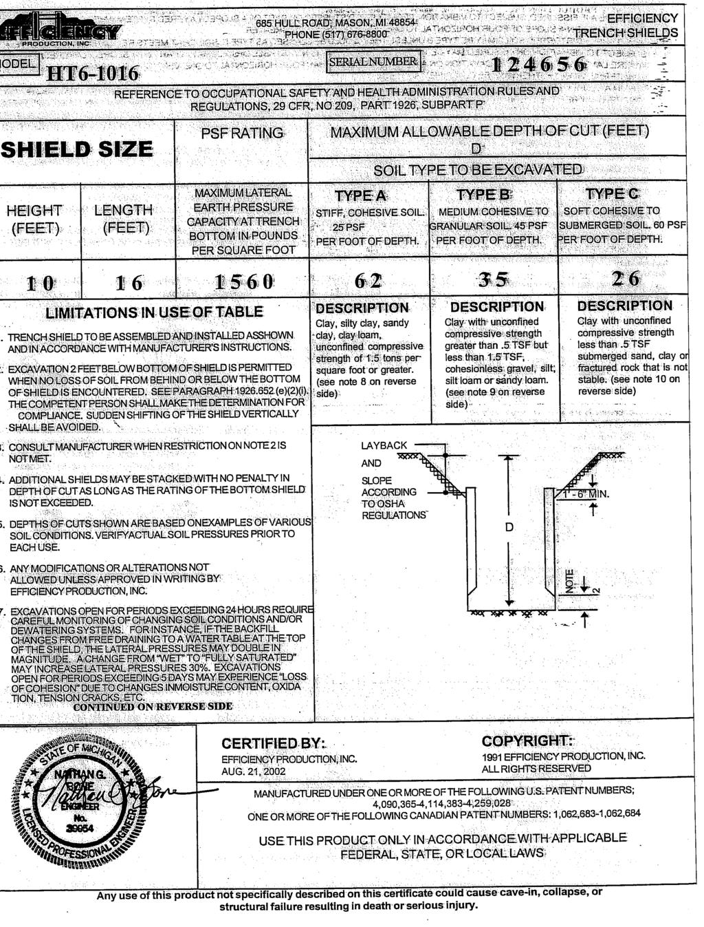
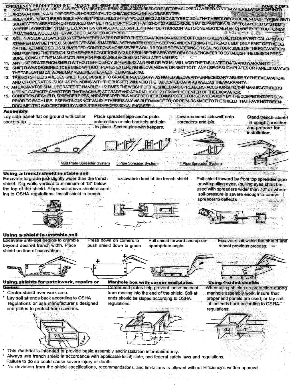
56 MODEL 685 HULL ROAD, MASON, MI PHONE (517) SERIAL NUMBER MHXLDW REFERENCE TO OCCUPATIONAL SAFETY AND HEALTH ADMINISTRATION RULES AND REGULATIONS, 29 CFR, NO 209, PART 1926, SUBPART P PAGE 1 OF 2 TRENCH SHIELD SHIELD SIZE HEIGHT LENGTH (FEET) (FEET) PSF RATING MAXIMUM LATERAL EARTH PRESSURE CAPACITY AT TRENCH BOTTOM IN POUNDS PER SQUARE FOOT MAXIMUM ALLOWABLE DEPTH OF CUT (FEET) D SOIL TYPE TO BE EXCAVATED TYPE B TYPE C-60 TYPE C-80 MEDIUM COHESIVE TO SOFT COHESIVE TO SOFT COHESIVE TO GRANULAR SOIL. 45 PSF SUBMERGED SOIL. 60 PSF SUBMERGED SOIL. 80 PSF PER FOOT OF DEPTH. PER FOOT OF DEPTH. PER FOOT OF DEPTH LIMITATIONS IN USE OF TABLE 1. TRENCH SHIELD TO BE ASSEMBLED AND INSTALLED AS SHOWN AND IN ACCORDANCE WITH MANUFACTURER S INSTRUCTIONS. 2. EXCAVATION 2 FEET BELOW BOTTOM OF SHIELD IS PERMITTED WHEN NO LOSS OF SOIL FROM BEHIND OR BELOW THE BOTTOM OF SHIELD IS ENCOUNTERED. SEE PARAGRAPH (e)(2)(i). THE COMPETENT PERSON SHALL MAKE THE DETERMINATION FOR COMPLIANCE. SUDDEN SHIFTING OF THE SHIELD VERTICALLY SHALL BE AVOIDED. 3. CONSULT MANUFACTURER WHEN RESTRICTION ON NOTE 2 IS NOT MET. 4. ADDITIONAL SHIELDS MAY BE STACKED WITH NO PENALTY IN DEPTH OF CUT AS LONG AS THE RATING OF THE BOTTOM SHIELD IS NOT EXCEEDED. 5. DEPTHS OF CUTS SHOWN ARE BASED ON EXAMPLES OF VARIOUS SOIL CONDITIONS. VERIFYACTUAL SOIL PRESSURES PRIOR TO EACH USE. DESCRIPTION Clay, with Unconfined Compressive Strength Greater than.5 TSF But Less than 1.5 TSF Cohesionless Gravel, Silt, Slit Loam or Sandy Loam. DESCRIPTION Soft Cohesive Soil Unconfined Compressive Strength Less than.5 TSF Gravel, Sand and Loamy Sand; Submerged Soil or fractured Rock that is not Stable. LAYBACK AND SLOPE AT A MINIMUM OF 1 TO 1 FOR B-SOILS, OR 1.5 TO 1 FOR C SOILS D DESCRIPTION Soft Cohesive Soil Unconfined Compressive Strength Less than.5 TSF Gravel, Sand and Loamy Sand; Submerged Soil or fractured Rock that is not Stable. 1-6 MIN. 6. ANY MODIFICATIONS OR ALTERATIONS NOT ALLOWED UNLESS APPROVED IN WRITING BY EFFICIENCY PRODUCTION, INC. 7. CONTRACTOR S COMPETENT/QUALIFIED PERSON SHALL BE RESPONSIBLE FOR MONITORING SOIL CONDITIONS AND SHALL BE RESPONSIBLE FOR COMPLIANCE WITH ALL FEDERAL, STATE AND LOCAL RULES AND REGULATIONS. 8. SPREADER PINS SHALL BE AISI C KSI MIN. YIELD AND NO MORE THAN 1/4 SMALLER THAN COLLAR AND SPREADER PIN HOLES AS MANUFACTURED BY EFFICIENCY PRODUCTION, INC. B-SOILS 1 (1 TO 1 SLOPE) 1 C-SOILS 1 (1.5 TO 1 SLOPE) 1.5 NOTE 2 CONTINUED ON REVERSE SIDE CERTIFIED BY: EFFICIENCY PRODUCTION, INC. COPYRIGHT: 1991 EFFICIENCY PRODUCTION, INC. ALL RIGHTS RESERVED MANUFACTURED UNDER ONE OR MORE OF THE FOLLOWING U.S. PATENT NUMBERS; 4,090,365-4,114,383-4,259,028 ONE OR MORE OF THE FOLLOWING CANADIAN PATENT NUMBERS: 1,062,683-1,062,684 USE THIS PRODUCT ONLY IN ACCORDANCE WITH APPLICABLE FEDERAL, STATE, OR LOCAL LAWS Any use of this product not specifically described on this certificate could cause cave-in, collapse, or structural failure resulting in death or serious injury.
 4 10 PSF RATING MAXIMUM LATERAL EARTH PRESSURE CAPACITY AT TRENCH BOTTOM IN POUNDS PER SQUARE FOOT LIMITATIONS")
(2)(i).")
57 685 HULL ROAD, MASON, MI PHONE (517) MODEL: MHXLSW-410 SERIAL NUMBER PAGE 1 OF 2 STEEL TRENCH SHIELD SHIELD SIZE HEIGHT (FEET) REFERENCE TO OCCUPATIONAL SAFETY AND HEALTH ADMINISTRATION RULES AND REGULATIONS, 29 CFR, NO 209, PART 1926, SUBPART P LENGTH (FEET) 4 10 PSF RATING MAXIMUM LATERAL EARTH PRESSURE CAPACITY AT TRENCH BOTTOM IN POUNDS PER SQUARE FOOT LIMITATIONS IN USE OF TABLE 1. TRENCH SHIELD TO BE ASSEMBLED AND INSTALLED IN ACCORDANCE WITH MANUFACTURER S INSTRUCTIONS. (SEE PAGE-2) EXCAVATION 2 FEET BELOW BOTTOM OF SHIELD IS PERMITTED WHEN NO LOSS OF SOIL FROM BEHIND OR BELOW THE BOTTOM OF SHIELD IS ENCOUNTERED. SEE PARAGRAPH (e)(2)(i). THE COMPETENT PERSON SHALL MAKE THE DETERMINATION FOR COMPLIANCE. SUDDEN SHIFTING OF THE SHIELD VERTICALLY SHALL BE AVOIDED. 3. DEPTH RATING IS BASED ON TEMPORARY LOADING, CONSULT MANUFACTURER IF SHIELD IS SUBJECT TO LONG TERM LOADING 4. ADDITIONAL SHIELDS MAY BE STACKED WITH NO PENALTY IN DEPTH OF CUT AS LONG AS THE RATING OF THE EACH SHIELD IS NOT EXCEEDED AT THE DEPTH IT IS USED. MANUFACTURER APPROVED STACKING METHOD MUST BE USED. 5. C-80 DOES NOT REPRESENT THE WORST POSSIBLE SOIL CONDITION. OBTAIN SITE- SPECIFIC ENGINEERING FOR EXTREMELY NON-STABLE CONDITIONS SUCH AS MARINE CLAY, PEAT, SOFT SUBMERGED AND FLOWING CLAYS, ETC. 6. ANY MODIFICATIONS OR ALTERATIONS NOT ALLOWED UNLESS APPROVED IN WRITING BY EFFICIENCY PRODUCTION, INC. 7. CONTRACTOR S COMPETENT/QUALIFIED PERSON SHALL BE RESPONSIBLE FOR MONITORING SOIL CONDITIONS AND SHALL BE RESPONSIBLE FOR COMPLIANCE WITH ALL FEDERAL, STATE AND LOCAL LAWS, RULES, AND REGULATIONS. EXAMPLES OF MAXIMUM ALLOWABLE DEPTH OF CUT (FEET) IN SOIL TYPE TO BE EXCAVATED TYPE B-45 (II) MEDIUM COHESIVE TO GRANULAR SOIL 45 PSF PER FT OF DEPTH TYPE C-60 (III) SOFT COHESIVE TO SATURATED SOIL. 60 PSF PER FT OF DEPTH TYPE C-80 (IV) SOFT SUBMERGED AND FLOWING SOIL. 80 PSF PER FT OF DEPTH 10 DESCRIPTION DESCRIPTION DESCRIPTION CLAY, WITH UNCONFINED COMPRESSIVE STRENGTH GREATER THAN 0.5 TSF BUT LESS THAN 1.5 TSF COHESIONLESS GRAVEL, SILT, SILT LOAM OR SANDY LOAM SOFT COHESIVE SOIL UNCONFINED COMPRESSIVE STRENGTH GREATER THAN 0.2 TSF, BUT LESS THAN 0.5 TSF CLAY, SAND AND LOAMY SAND; SATURATED SOIL THAT IS STABLE, DRY SAND, OR DEWATERED SOILS 8 SOFT COHESIVE SOIL UNCONFINED COMPRESSIVE STRENGTH LESS THAN 0.2 TSF. FRACTURED ROCK THAT IS NOT STABLE, OR SUBMERGED SAND AND LOAMY SAND THAT IS FLOWING. (SEE NOTE 5) 8. SPREADER PINS SHALL BE 8620 COLD DRAWN KSI MIN. YIELD AND NO MORE THAN 1/4 SMALLER THAN COLLAR AND SPREADER PIN HOLES AS MANUFACTURED BY EFFICIENCY PRODUCTION, INC. CONTINUED ON REVERSE SIDE MANUFACTURED UNDER ONE OR MORE OF THE FOLLOWING U.S. PATENT NUMBERS: 4,090,365-4,114,383-4,259,028 ONE OR MORE OF THE FOLLOWING CANADIAN PATENT NUMBERS: 1,062,683-1,062,684 CERTIFIED BY: EFFICIENCY PRODUCTION INC. COPYRIGHT: 1991 EFFICIENCY PRODUCTION INC. ALL RIGHTS RESERVED ANY USE OF THIS PRODUCT NOT SPECIFICALLY DESCRIBED ON THIS CERTIFICATE COULD CAUSE IN CAVE-IN, COLLAPSE, OR STRUCTURAL FAILURE RESULTING IN DEATH OR SERIOUS INJURY
58
59
60
61
 25 35 45 60 80 Depth \"H\" (feet) 50 50 50 40 31 This shield is manufactured to meet the requirements of O.")
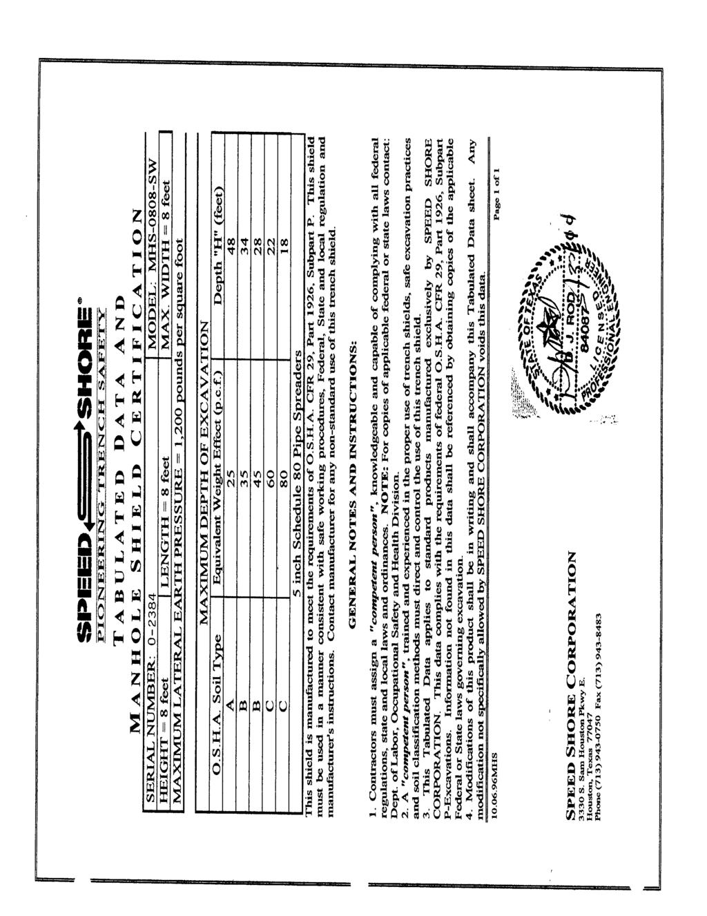
62 T A B U L A T E D D A T A A N D M A N H O L E S H I E L D C E R T I F I C A T I O N SERIAL NUMBER: MODEL: MHS DW-RC HEIGHT = 8 feet SQUARE = 10 feet THICKNESS= 4 inches MAXIMUM LATERAL EARTH PRESSURE = 2,238 Pounds per square foot O.S.H.A. Soil Type A B B C C MAXIMUM DEPTH OF EXCAVATION Equivalent Weight Effect (p.c.f.) Depth "H" (feet) This shield is manufactured to meet the requirements of O.S.H.A. CFR 29, Part 1926, Subpart P. This shield must be used in a manner consistent with safe working procedures, Federal, State and local regulation and manufacturer's instructions. Contact manufacturer for any non-standard use of this manhole shield. GENERAL NOTES AND INSTRUCTIONS: 1. Contractors must assign a "competent person", knowledgeable and capable of complying with all federal regulations, state and local laws and ordinances. NOTE: For copies of applicable federal or state laws contact: Dept. of Labor, Occupational Safety and Health Division 2. A "competent person", trained and experienced in the proper use of trench shields, safe excavation practices and soil classification methods must direct and control the use of this trench shield. 3. This Tabulated Data applies to standard products manufactured exclusively by SPEED SHORE CORPORATION. This data complies with the requirements of federal O.S.H.A. CFR 29, Part 1926, Subpart P- Excavations. Information not found in this data shall be referenced by obtaining copies of the applicable Federal or State laws governing excavation 4. Modifications of this product shall be approved by the manufacturer in writing and shall accompany this Tabulated Data sheet. Any modification not specifically allowed by SPEED SHORE CORPORATION voids this data Page 1 of 1 SPEED SHORE CORPORATION 3330 S. Sam Houston Pkwy. East Houston, Texas Phone (713) Fax (713)
63
64
65
66
67
68
69
70
71
72
73
 A 25 B 35 B 45 C 60 C 80 O.S.H.A. Soil Type Spreader Size = 8 inch Schedule 80 Pipe / Maximum Spreader Length = 20 feet This shield is manufactured to meet the requirements of O.")
74 T A B U L A T E D D A T A A N D T U F F - L I T E C E R T I F I C A T I O N SERIAL NUMBER: MODEL: TS-0624TL6 HEIGHT = 6 feet LENGTH = 24 feet THICKNESS= 6 inches MAXIMUM LATERAL EARTH PRESSURE = 959 Pounds per square foot MAXIMUM DEPTH OF EXCAVATION Equivalent Weight Effect (p.c.f.) A 25 B 35 B 45 C 60 C 80 O.S.H.A. Soil Type Spreader Size = 8 inch Schedule 80 Pipe / Maximum Spreader Length = 20 feet This shield is manufactured to meet the requirements of O.S.H.A. CFR 29, Part 1926, Subpart P. This shield must be used in a manner consistent with safe working procedures, Federal, State and local regulation and manufacturer's instructions. Contact manufacturer for any non-standard use of this trench shield. GENERAL NOTES AND INSTRUCTIONS: Depth "H" (feet) 1. Contractors must assign a "competent person", knowledgeable and capable of complying with all federal regulations, state and local laws and ordinances. NOTE: For copies of applicable federal or state laws contact: Dept. of Labor, Occupational Safety and Health Division 2. A "competent person", trained and experienced in the proper use of trench shields, safe excavation practices and soil classification methods must direct and control the use of this trench shield. 3. This Tabulated Data applies to standard products manufactured exclusively by SPEED SHORE CORPORATION. This data complies with the requirements of federal O.S.H.A. CFR 29, Part 1926, Subpart P- Excavations. Information not found in this data shall be referenced by obtaining copies of the applicable Federal or State laws governing excavation 4. Modifications of this product shall be approved by the manufacturer in writing and shall accompany this Tabulated Data sheet. Any modification not specifically allowed by SPEED SHORE CORPORATION voids this data Page 1 of SPEED SHORE CORPORATION 3330 S. Sam Houston Pkwy. East Houston, Texas Phone (713) Fax (713)
75
76
77
78
79
80
81
82
83
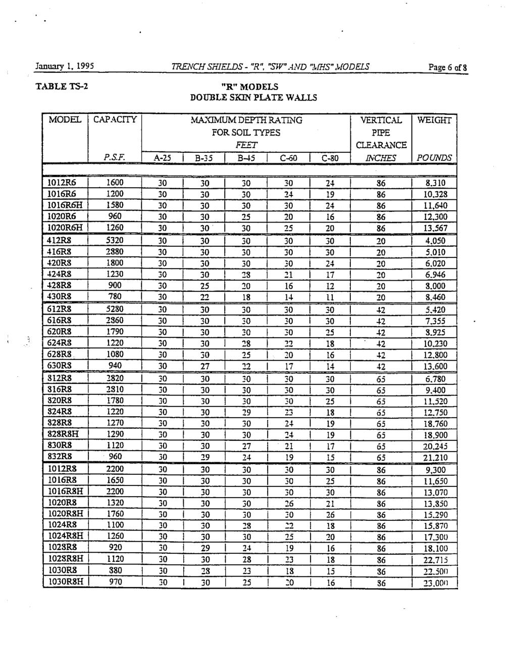
SPEED SHORE MANUFACTURER S TABULATED DATA "MHS" MODELS. STEEL MANHOLE SHIELDS 4 Single Wall 4 Double Wall 4 Double Wall with Cut-Outs
 SPEED SHORE MANUFACTURER S TABULATED DATA "MHS" MODELS STEEL MANHOLE SHIELDS 4 Single Wall 4 Double Wall 4 Double Wall with Cut-Outs January 01, 2005 3330 S. SAM HOUSTON PKWY E. HOUSTON, TEXAS 77047 Tel:
STEEL TRENCH SHIELDS DW MODELS
 STEEL TRENCH SHIELDS DW MODELS 3330 S. SAM HOUSTON PKWY E. HOUSTON, TEXAS 77047 Phone: 713.943.0750 Toll Free: 800.231.6662 Fax: 713. 943.8483 COPYRIGHT, U.S.A., SPEED SHORE CORPORATION, 2009 April 16,
"STEEL FRAMED" ALUMINUM PANEL SHIELDS
 "STEEL FRAMED" ALUMINUM PANEL SHIELDS MANUFACTURE S TABULATED DATA 3330 S. Sam Houston Pkwy Houston, Texas 77047 (713)943-0750 USA Toll Free 1-800-231-6662 Fax (713)943-8483 Www.speedshore.com PRINTED
STEEL TRENCH SHIELDS TUFF-LITE MODELS
 STEEL TRENCH SHIELDS TUFF-LITE MODELS 3330 S. SAM HOUSTON PKWY E. HOUSTON, TEXAS 77047 Phone: 713.943.0750 Toll Free: 800.231.6662 Fax: 713. 943.8483 April 16, 2009 TRENCH SHIELDS TUFF-LITE TM Page 2 of
SPEED SHORE MANUFACTURER S TABULATED DATA MANGUARDS. October 31, 2005
 SPEED SHORE MANUFACTURER S TABULATED DATA MANGUARDS October 31, 2005 3330 S. SAM HOUSTON PKWY E. HOUSTON, TEXAS 77047 Tel: (713) 943-0750 U.S.A. Toll Free: (800) 231-6662 Fax: (713) 943-8483 COPYRIGHT,
MODULAR ALUMINUM PANEL SHIELDS MAPS
 MODULAR ALUMINUM PANEL SHIELDS MAPS 3330 S. SAM HOUSTON PKWY E. HOUSTON, TEXAS 77047 Phone: 713.943.0750 Toll Free: 800.231.6662 Fax: 713. 943.8483 April 16, 2009 MODULAR ALUMINUM PANEL SHIELDS Page 2
SLIDE RAIL INSTALLATION GUIDE MANUFACTURE S TABULATED DATA
 SLIDE RAIL INSTALLATION GUIDE MANUFACTURE S TABULATED DATA 3330 S. Sam Houston Pkwy Houston, Texas 77047 (713)943-0750 USA Toll Free 1-800-231-6662 Fax (713)943-8483 Www.speedshore.com PRINTED IN U.S.A.
"DW" TRENCH SHIELDS "SP" TRENCH SHIELDS "TL" TRENCH SHIELDS "SW" TRENCH SHIELDS MANHOLE SHIELDS
 "DW" TRENCH SHIELDS "SP" TRENCH SHIELDS "TL" TRENCH SHIELDS "SW" TRENCH SHIELDS MANHOLE SHIELDS DETAILED SPECIFICATIONS (sample) ASSEMBLY AND INSTALLATION PROCEDURES MANUFACTURE S TABULATED DATA 3330 S.
VERTICAL SHORES TRENCH RESCUE SHORES MEGA-SHORES
 VERTICAL SHORES DETAILED SPECIFICATIONS INSTALLATION MANUFACTURE S TABULATED DATA TRENCH RESCUE SHORES DETAILED SPECIFICATIONS MANUFACTURE S TABULATED DATA MEGA-SHORES MANUFACTURE S TABULATED DATA 3330
Tabulated Data Lite-Shield 20 System
 Tabulated Data Lite-Shield 20 System November, 2014 Copyright, U.S.A.,Griswold Machine & Eng., 2012 594 Mendon Road, Union City, MI 49094 (800) 248-2054 Fax: (517) 741-7483 CAUTION EXCAVATION PROCEDURES
Aluminum Sheeting Guide (ASG)
") Tabulated Data Aluminum Sheeting Guide (ASG) February 2016 Copyright, U.S.A.,Griswold Machine & Eng., 2016 594 Mendon Road, Union City, MI 49094 (800) 248 2054 Fax: (517) 741 7483 CAUTION EXCAVATION PROCEDURES
Tabulated Data Aluminum Sheeting Guide (ASG) February 2016 Copyright, U.S.A.,Griswold Machine & Eng., 2016 594 Mendon Road, Union City, MI 49094 (800) 248 2054 Fax: (517) 741 7483 CAUTION EXCAVATION PROCEDURES
TAO Safety Policy No. HS-5.1 Page 1 of 15 Revision No. 2 Revision Date: July 19, 2005
 TAO Safety Policy No. HS-5.1 Page 1 of 15 Revision No. 2 1.0 OVERVIEW This safety policy provides guidance for conducting trenching and excavation activities at project sites. Emphasis is placed on sloping
PACIFIC SHORING, LLC ALUMINUM SHORING PRODUCTS PSH HEAVY DUTY HYDRAULIC WALER RAIL SYSTEM. TABULATED DATA Effective December 10, 2013
 1 HEAVY DUTY HYDRAULIC WALER RAIL SYSTEM Effective December 10, 2013 PSH 265 Roberts Avenue Santa Rosa, Ca. 95407 (707) 575-9014 Construction Engineering Resource 1837 Wright Street Santa Rosa, Ca. 95404
PACIFIC SHORING, LLC ALUMINUM SHORING PRODUCTS HEAVY DUTY HYDRAULIC WALER RAIL SYSTEM. TABULATED DATA Effective August 25, 2015
 1 HEAVY DUTY HYDRAULIC WALER RAIL SYSTEM Effective August 25, 2015 PSH 265 Roberts Avenue Santa Rosa, Ca. 95407 (707) 575-9014 Construction Engineering Resource 1837 Wright Street Santa Rosa, Ca. 95404
Safety Policy and Procedure
 Safety Policy and Procedure Policy Number 004 Authorized By: The Cianbro Companies Alan Burton Title: Excavation Safety Effective Date: 01/01/75 Page 1 of 16 1 Status 1.1 Update of existing policy, effective
ITEM 400 STRUCTURAL EXCAVATION AND BACKFILL
 AFTER MARCH 1, 2012 ITEM 400 STRUCTURAL EXCAVATION AND BACKFILL 400.1 Description. This item shall govern for all excavation required for the construction of all structures, except pipe or box sewers for
DREW UNIVERSITY FALL PROTECTION PROCEDURE (DRAFT 12/11)
") PURPOSE The objective of this policy & guideline is to eliminate the potential for injuries and fatalities to employees and contractors resulting from falls from elevated work areas at Drew University
PURPOSE The objective of this policy & guideline is to eliminate the potential for injuries and fatalities to employees and contractors resulting from falls from elevated work areas at Drew University
BP OIL -- TOLEDO REFINERY
 BP OIL -- TOLEDO REFINERY Toledo Refinery Procedure No.: SAF 054 Effective Date: June 29, 2017 Ground Disturbance Rev. No.: 11 Revised By: Mario Rizo Auth. By: Chris Conley (Signature of file) Page 1 of
FALL PROTECTION COMPARISON BETWEEN VARIOUS OSHA STANDARDS, NAVY and EM 385 (2008) REQUIREMENTS
 REQUIREMENTS") Requirements FALL PROTECTION COMPARISON BETWEEN VARIOUS OSHA STANDARDS, NAVY and EM 385 (2008) REQUIREMENTS Navy FP Chapter 13 of OPNAVINST 5100.23G (2005) and Fall Protection Guide for Ashore Facilities
Requirements FALL PROTECTION COMPARISON BETWEEN VARIOUS OSHA STANDARDS, NAVY and EM 385 (2008) REQUIREMENTS Navy FP Chapter 13 of OPNAVINST 5100.23G (2005) and Fall Protection Guide for Ashore Facilities
CHAPTER 10 FALL PROTECTION
 CHAPTER 10 FALL PROTECTION A. INTRODUCTION... 1 B. CHAPTER-SPECIFIC ROLES and RESPONSIBILITIES... 2 C. HAZARD IDENTIFICATION... 3 1. Job Hazard Analysis (Jha).... 3 2. Fall Hazards... 3 D. HAZARD CONTROL...
Reliance Industries, LLC Operating instructions for the / Bolt-on D-Ring Anchorage. Model # 3071
 Reliance Industries, LLC Operating instructions for the 3071-1 / 3071-2 Bolt-on D-Ring Anchorage Model # 3071 Reliance Industries, LLC PO Box 140008 Denver, CO 80214 Ph. (800) 488-5751 Ph. (303) 424-8650
This section applies to all open excavations made in the earth's surface. Excavations are defined to include trenches.
 Appendix H Specific Excavation Requirements This section applies to all open excavations made in the earth's surface. Excavations are defined to include trenches. Surface encumbrances All surface encumbrances
Excavation and Trenching
 Excavation and Trenching An excavation is defined as any man-made cut, cavity, trench, or depression in the earth s surface formed by earth removal. Trenches are narrow, underground excavations that are
User Instructions 1789 Parapet Wall Anchor
 User Instructions 1789 Parapet Wall Anchor This manual is intended to meet the Manufacturer Instructions as required by ANSI Z359.1 and should be used as part of an employee training program as required
TRENCHING/SHORING/EXCAVATIONS Revision Date: 04/2017
 TRENCHING/SHORING/EXCAVATIONS 41.1 PURPOSE 41.1.1 The purpose of this policy is to provide guidance and instruction to safely perform work around or in excavations or trenches and protect employees from
Standard Pneumatic Test Procedure Requirements for Piping Systems
 the pressure equipment safety authority Standard Pneumatic Test Procedure Requirements for Piping Systems AB-522 Edition 2, Rev. 1 Issued 2016-10-24 Table of Contents FOREWORD... 1 1.0 INTRODUCTION...
SECTION FACILITY FALL PROTECTION PART I - GENERAL
 SECTION 11 24 29 - FACILITY FALL PROTECTION PART I - GENERAL 1.1 The Illinois Department of Labor (IDOL) regulates fall protection for general industry and construction in the public sector under the Illinois
Compressed Gases and Cryogens
 Compressed Gases and Cryogens University of Tennessee Safety Guide HM-011 Document Contact: EHS Date effective: January 1, 2009 Revision Date: October 1, 2015 Purpose This guideline adheres to the Occupational
FALL PROTECTION / ELEVATED WORK
 SEPTEMBER CORE REFRESHER HSE TOOL BOX FALL PROTECTION / ELEVATED WORK FALL PROTECTION Falls from elevations are one of the most common causes of death in this industry. OSHA requires fall protection when
Excavations and Trenches
 Purpose Excavation and trenching are among the most hazardous work activities undertaken by the TNRD. This document outlines general requirements and specific safe work procedures to ensure the health
??????? is committed to providing a safe work environment for its employees and preventing occupational injuries due to falls.
 Intent??????? is committed to providing a safe work environment for its employees and preventing occupational injuries due to falls. Fall Protection is an integral part of our commitment to a safe work
A N C H O R T A B S N O R T H W E S T ANCHOR TAB VF. Patented. User Instructions
 A N C H O R T A B S N O R T H W E S T www.anchortabs.com ANCHOR TAB VF Patented User Instructions National standards, and state, provincial, and federal laws, require installer/user of this product to
GEMTOR. ... when your life is on the line OWNER'S MANUAL. FLW Series Self-Retracting Lanyard/Fall Limiter
 GEMTOR TM... when your life is on the line OWNER'S MANUAL FLW Series Self-Retracting Lanyard/Fall Limiter Installation, Operating, Inspection and Maintenance Instructions Warning You must read and fully
8. Fall Protection Procedures WAC
 1.0 Fall Protection Introduction 8. Fall Protection Procedures WAC 296-155-245 If an employee is exposed to a fall hazard of ten (10) feet or more in height, the employee must use a fall restraint, fall
Risk Control at United Fire Group
 In the United States, falls are the leading cause of fatalities on a construction site. Employers and employees need to do the following: Where protection is required, select fall protection systems appropriate
GOM Diving Safety Work Group
 GOM Diving Safety Work Group COMMITTEE WORK GROUP Underwater Excavation with Hand Jetting July 14, 2015 DISCLAIMER This US GOM DSWG document is not meant to be all inclusive, and not every rule and regulation
Item 404 Driving Piling
 Item Driving Piling 1. DESCRIPTION Drive piling. 2. EQUIPMENT 2.1. Driving Equipment. Use power hammers for driving piling with specified bearing resistance. Use power hammers that comply with Table 1.
INSTRUCTIONS FOR USE
 INSTRUCTIONS FOR USE 7100 Series Lanyards Complies with the current ANSI Z359.1-2007 and all applicable OSHA regulations and requirements. Reliance Industries P.O. Box 2046 Deer Park, TX 77536 Phone :
Minimum Safety Requirements for Contractors Working on Railway Property
 Minimum Safety Requirements for Contractors Working on Railway Property Effective_ April 1, 2007 Introduction Canadian Pacific is committed to provide a Safe and Healthy working environment for all Railway
INSTRUCTIONS FOR USE
 Rebar Chain Assembly INSTRUCTIONS FOR USE 7260XX Rebar Chain Assembly Complies with the current ANSI Z359.1-2007 and all applicable OSHA regulations and requirements. Reliance Industries P.O. Box 2046
Fall Protection Resource Guide P AGE 1
 Fall Protection Resource Guide P AGE 1 As a Home Builder, we do not self-perform any work. This section is a resource guide only and is not intended to put any requirements on the company. All subcontractors,
HEALTH AND SAFETY PROGRAM 201 HOT TAP PERMIT/FILLET WELD REPAIRS
 Page 1 of 15 1.0 PURPOSE 1.1. Axiall, Plaquemine Complex, has developed this Hot Tap Permit Program to eliminate potential accidents, injuries, and to enhance employee protection. 1.2. To provide for the
Regulations Respecting Compressed Gas Pressure Vessels
 COMPRESSED GAS PRESSURE VESSELS SR 99/70 1 Regulations Respecting Compressed Gas Pressure Vessels Repealed by Chapter B-5.1 Reg 1 (effective January 1, 2007) Formerly Saskatchewan Regulations 99/70 (effective
DUQUESNE UNIVERSITY LOCKOUT/TAGOUT PROGRAM
 DUQUESNE UNIVERSITY LOCKOUT/TAGOUT PROGRAM Prepared by: Environmental Health and Safety Department TABLE OF CONTENTS Page Purpose 1 Scope 1 Introduction 2 Regulatory Requirements 2 Protective Materials
General Safety and Health Provisions for Construction Self Inspection Checklist
 Optional Information Name of School: Date of Inspection: Vocational Program/Course/Room: Signature of Inspector: General Safety and Health Provisions for Construction Self Inspection Checklist Instructions:
Health & Safety Policy and Procedures Manual SECTION 25 RIGGING AND HOISTING EQUIPMENT
 SECTION 25 RIGGING AND HOISTING EQUIPMENT 1. RIGGING AND HOISTING: These rules apply to all Maul Electric, Inc. employees and subcontractors. Note: Maul Electric, Inc. employees will utilize mechanical
WHEATLEY Series 822/820 Swing Check Valve
 Document Number: TC003001-12 Revision: 02 WHEATLEY Series 822/820 Swing Check Valve Installation, Operation, and Maintenance Manual TABLE OF CONTENTS BILL OF MATERIALS...3 SCOPE...4 INSTALLATION AND OPERATION
QUALITY ASSURANCE SPECIFICATION NONDESTRUCTIVE EXAMINATION PAGE 1 OF 7
 QUALITY ASSURANCE SPECIFICATION REVISION: 0 DATE: 08/29/14 NONDESTRUCTIVE EXAMINATION PAGE 1 OF 7 1.0 Purpose The purpose of this specification is to establish the minimum quality assurance requirements
SECTION BUTTERFLY VALVES
 SECTION 15112 BUTTERFLY VALVES PART 1 GENERAL 1.01 SUMMARY A. All butterfly valves shall be of the tight closing, rubber seated type and fully comply with the latest revision of AWWA Standard C504, Class
IAPMO IS PUBLIC REVIEW DRAFT Thrust Blocking for Rubber Gasketed and Solvent Cement Joints
 IAPMO IS 33-2019 PUBLIC REVIEW DRAFT Thrust Blocking for Rubber Gasketed and Solvent Cement Joints IAPMO Standard IAPMO IS 33 2019 Published: Month Year Published by International Association of Plumbing
PUSH PIER SYSTEMS STABILITY. SECURITY. INTEGRITY. Push Pier Systems PN #MBPPT
 PUSH PIER SYSTEMS STABILITY. SECURITY. INTEGRITY. PN #MBPPT Push Pier Systems About Foundation Supportworks is a network of the most experienced and knowledgeable foundation repair and new construction
Construction Dewatering
 Construction Dewatering Introduction The control of groundwater is one of the most common and complicated problems encountered on a construction site. Construction dewatering can become a costly issue
User Instruction Manual Fixed Beam Anchor
 Instructions for the following series products: FIXED BEAM ANCHOR Model Numbers: The Ultimate in Fall Protection 2108406 2108407 2108408 2108409 2108410 2108411 User Instruction Manual Fixed Beam Anchor
Confined Space in Construction
 Confined Space in Construction 1926.1201 1926.1213 Confined space means a space that: 1. Is large enough and so configured that an employee can bodily enter it; 2. Has limited or restricted means for entry
Equipment Operation Procedures
 Procedures Purpose It is the policy of this company to permit only trained and authorized personnel to operate construction equipment. These procedures are applicable to both daily operators, and those
Operating instructions. Bolt-on Bar Joist Anchorage
 Reliance Industries, LLC Operating instructions for the Bolt-on Bar Joist Anchorage Model # 3072 Reliance Industries, LLC PO Box 140008 Denver, CO 80214 Ph. (800) 488-5751 Ph. (303) 424-8650 Fax (303)
FXT. FXT Cooling Tower RIGGING & ASSEMBLY INSTRUCTIONS
 FXT FXT Cooling Tower RIGGING & ASSEMBLY INSTRUCTIONS FXT Cooling Towers should be rigged and assembled as outlined in this bulletin. These procedures should be thoroughly reviewed prior to the actual
Lockout/Tagout Plan Environmental Health & Safety Office July 2017
 July 2017 Table of Contents Acronyms... iii Foreword... iv Document History... iv 1.0 Introduction... 1 1.1 Purpose... 1 1.2 Scope... 1 1.3 Lockout/Tagout Program... 1 2.0 Roles and Responsibilities...
VACUUM TESTING PRECAST CONCRETE MANHOLES
 1 OF 5 testing is a quick, safe and practical way to validate manhole system integrity. Manhole sections can be tested at the precast concrete plant prior to delivery or on site prior to backfilling. Here
Pannier Corporation Health and Safety Handbook Marking System Group Aerial Lifts Original Date: Section: Revision date: Page: 12/5/ of 11
 12/5/2013 37 1 of 11 1.0 Overview Aerial lifts are commonly used in construction, inspection, athletic events and repair services to lift Pannier employees to an elevated work position. Proper operation
USER INSTRUCTIONS. Complies with ANSI Z359.1, ANSI Z359.4 standards and OSHA 29 CFR 1910 and 1926 regulations.
 FALL PROTECTION USER INSTRUCTIONS TRIPOD SYSTEM Complies with ANSI Z359.1, ANSI Z359.4 standards and OSHA 29 CFR 1910 and 1926 regulations. Models: T100009, T210030B, T210060B, T210100B, T510000B, T510045,
Pole Foundation Design with Spreadsheet
 PDHonline Course S235 (1 PDH) Pole Foundation Design with Spreadsheet Instructor: John W. Andrew, PE 2012 PDH Online PDH Center 5272 Meadow Estates Drive Fairfax, VA 22030-6658 Phone & Fax: 703-988-0088
The purpose of this training is to give field technicians awareness training and guidelines on potential hazards they may encounter in the field.
 Purpose The purpose of this training is to give field technicians awareness training and guidelines on potential hazards they may encounter in the field. Fall Protection and Prevention JELD-WEN Field Employees
RATCHET RELEASE SHACKLE
 RATCHET RELEASE SHACKLE INNOVATIVE PILING EQUIPMENT HYDRAULIC PILING HAMMERS EURO RATCHET RELEASE SHACKLE FOR STEEL ERECTION OPERATORS INSTRUCTIONS & SPARE PARTS LIST EXCAVATOR MOUNTED VIBRATORS EXCAVATOR
User Instructions 1790 Rail Anchor
 User Instructions 1790 Rail Anchor This document is intended to meet the Manufacturer s Instruction requirements as stated by ANSI Z359.1, and should be used as part of an employee training program as
Confined Space Entry Program
 Confined Space Entry Program August 2016 Table of Contents Purpose... 1 Scope and Application... 1 Responsibilities... 2 Environmental Health and Safety (EH&S)... 2 Entry Supervisor... 2 Attendant... 2
Take the high road to ensure underground safety.
 Take the high road to ensure underground safety. UnitedRentals.com 800.UR.RENTS 2017 United Rentals, Inc. 2 Trench Safety Power Trench & Safety HVAC 3 Excavations often cost more and take longer than needed.
Fall Protection / Open Holes & Guardrail
 Fall Protection / Open Holes & Guardrail 1. Leading Edges Policy Statement It is GW Communications policy that any worker exposed to a fall 6 or greater, shall be protected from coming into contact with
MSC Guidelines for Independent Fuel Tanks
 References: Contact Information a. 46 CFR 58.50 (Independent Fuel Tanks) b. 46 CFR 119.440 (Independent Fuel Tanks) c. 46 CFR 182.440 (Independent Fuel Tanks) C. J. Robuck, LCDR, Chief, Engineering Division
 1 2 CONTENTS INTRODUCTION Owner Information 4 Warranty Registration 5 Safety Instructions Safety 6 Safety Decals 7 Safety Identification Labels 8 Safety Notice 10 Safety Standards 11 Risk Assessment 13
LAMINATED POLES. engineered to solve problems. Coastal Douglas-fir. Field Raked and Tangent Poles
 Coastal Douglas-fir Field Raked and Tangent Poles LAMINATED POLES engineered to solve problems 1 Design Criteria Submission Form You can either fax this information to 253-627-4188 or submit your drawings
Civil Application Solutions
 Civil Application Solutions Features - Chiseled Cutting Edges - Increased Surface Area - Lateral Direction Guide Ribs Benefits - Faster Installation and Penetrates Harder Soils - Quicker Loading, Stronger
Fall Protection- Part 2
 Optional Information Name of School: Date of Inspection: Vocational Program/Course/Room: Signature of Inspector: Fall Protection- Part 2 Self Inspection Checklist Instructions: This checklist covers fall
Scope: This plan applies to all personnel, including contractors, who enter or work in confined spaces, or supervise such activities.
 11/13/1995 4 5/20/2013 1 of 10 Authority and Scope Regulation: 29 CFR 1910.146 Scope: This plan applies to all personnel, including contractors, who enter or work in confined spaces, or supervise such
310 SERIES TILT-TO-LOAD ROTATOR. The Specialist In Drum Handling Equipment
 OPERATOR S MANUAL FOR MORSE TILT-TO-LOAD DRUM ROTATOR SAFETY INFORMATION: While Morse Manufacturing Co. drum handling equipment is engineered for safety and efficiency, a high degree of responsibility
Aerial Lift Safety Program
 Aerial Lift Safety Program Revision Date: 6-19-2017 TABLE OF CONTENTS Aerial Lift Safety Program 1.0 Overview... 3 2.0 Policy......3 3.0 Requirements. 3 4.0 Purpose..... 4 5.0 Scope.........4 6.0 Responsibilities........7
OSHA 30 Syllabus. Laborers Training School. Time: 40 hours. Maximum Class Size: 30. Prerequisites: None
 Time: 40 hours Maximum Class Size: 30 Prerequisites: None Course Description: The 40-hour OSHA Outreach Training Program provides training for workers and employers on the recognition, avoidance, abatement,
FEE SCHEDULE POOL PERMIT FEES. Refundable Security (Cash of L.C.) 1 Hot Tub, Spa, etc. $ nil 2 Above Ground Pool $ nil
 1 Hot Tub, Spa, etc. $ nil 2 Above Ground Pool $ nil") FEE SCHEDULE POOL PERMIT FEES Type of Pool Total Fee Refundable Security (Cash of L.C.) 1 Hot Tub, Spa, etc. $100.00 nil 2 Above Ground Pool $200.00 nil 3 Inground Pools (assumed $350.00 $1500.00 subdivision)
FEE SCHEDULE POOL PERMIT FEES Type of Pool Total Fee Refundable Security (Cash of L.C.) 1 Hot Tub, Spa, etc. $100.00 nil 2 Above Ground Pool $200.00 nil 3 Inground Pools (assumed $350.00 $1500.00 subdivision)
1) INTRODUCTION 2) THE UNFAIR ADVANTAGE
 INTRODUCTION 2) THE UNFAIR ADVANTAGE") 1 1) INTRODUCTION 2) THE UNFAIR ADVANTAGE and Stingray earth anchors are driven tipping plate soil anchors for reaction of tensile loads. anchors have ultimate capacities up to 20 tons, and Stingray anchors
1 1) INTRODUCTION 2) THE UNFAIR ADVANTAGE and Stingray earth anchors are driven tipping plate soil anchors for reaction of tensile loads. anchors have ultimate capacities up to 20 tons, and Stingray anchors
FALL PROTECTION
 115500 FALL PROTECTION PART 1 GENERAL 1.01 General A. Cornell University seeks to prevent exposures to fall hazards whenever possible and protect personnel that may be exposed to fall hazards. Therefore,
TRENCH AND EXCAVATION COLLAPSE
 TRENCH AND EXCAVATION COLLAPSE A. GENERAL This guideline provides operational guidance at rescue incidents that involve the location, disentanglement and removal of victims from sub-surface trench and
Confined Space Entry
 Confined Space Entry Purpose The purpose of this chapter is to establish methods to identify confined spaces, classify them according to their risks, and establish guidelines necessary for the safe preparation,
Department of the Interior Departmental Manual
 Department of the Interior Departmental Manual Effective Date: 3/12/99 Series: Safety Management Part 485: Safety and Occupational Health Program Chapter 27: Underwater Diving Safety Originating Office:
Reviewed: New Effective: 5/18/12 Supersedes: New Preparer: Owner: Approver: Team Member, Occupational Safety Industrial Hygiene
 Procedure No.: BC032.027 Page: 1 of 15 Preparer: Owner: Approver: Team Member, Occupational Safety Industrial Hygiene Manager, Occupational Safety Industrial Hygiene Vice President, Ecology & Safety (Signature
GENERAL GUIDELINES FOR PROPER RIGGING PRACTICES AND INSPECTION & REMOVAL CRITERIA FOR SLINGS PER OSHA
 GENERAL GUIDELINES FOR PROPER RIGGING PRACTICES AND INSPECTION & REMOVAL CRITERIA FOR SLINGS PER OSHA 1910.184 SAFE OPERATING PRACTICES -.Whenever any sling is used, the following practices shall be observed:
Hot Tapping Machine. OPERATIONS MANUAL and OPERATING INSTRUCTIONS
 262-2040 Hot Tapping Machine For performing 1/4 6 Hot taps 285 psi or less. Municipal Water, Sewage, & Building Services Use OPERATIONS MANUAL and OPERATING INSTRUCTIONS WARNING: These instructions are
Energy Control. Suite 2A, 55 Frid Street Hamilton, ON L8P 4M3 office: cell:
 Energy Control Suite 2A, 55 Frid Street Hamilton, ON L8P 4M3 office: 905.577.0303 cell: 905.977.0210 consultant@staffaid.ca www.staffaid.com Safety, Energy Control, Power Lockout & Function Test Procedures
Roughneck TM Mesh Slings
 Roughneck TM Slings ROUGHNECK WIRE MESH SLINGS Widely used in metalworking shops and steel warehouses where loads are abrasive, hot or tend to cut web slings Features and Benefits Promotes Safety Steel
OWNER'S MANUAL. Turnbuckle. Stanchions. Warning
 GEMTOR, INC....when your life is on the line One Johnson Avenue Matawan, NJ 07747 732-583-6200 800-405-9048 Fax 732-290-9391 OWNER'S MANUAL Installation, Operating, Inspection and Maintenance Instructions
EM385 Construction Safety and Health Certification Course Section 12 Control of Hazardous Energy
 EM385 Construction Safety and Health Certification Course Section 12 Control of Hazardous Energy OSHAcademy Course 501 Study Guide EM 385 SAFETY AND HEALTH CERTIFICATION COURSE - SECTION 12 Edited by:
Health & Safety Policy and Procedures Manual SECTION 6 ELECTRICAL SAFETY / CONTROL OF HAZARDOUS ENERGY
 SECTION 6 ELECTRICAL SAFETY / CONTROL OF HAZARDOUS ENERGY 1. CONTROL OF HAZARDOUS ENERGY POLICY AND PROCEDURES A. OSHA References: 29 CFR 1910.147, 29 CFR 1910.332, 29 CFR 1910.333, 29 CFR 1926.417 B.
WHEATLEY Series 500 Swing Check Valve
 Document Number: TC003001-13 Revision: 02 WHEATLEY Series 500 Swing Check Valve Installation, Operation, and Maintenance Manual TABLE OF CONTENTS BILL OF MATERIALS...3 SCOPE...5 INSTALLATION AND OPERATION
DBML-60/80 Squeeze Tool
 DBML-60/80 Squeeze Tool OPERATORS MANUAL Description The Mustang Model DBML-60/80 Hydraulic squeeze tool has been manufactured since 1995. A Mustang 3 3/4 bore doubleacting cylinder producing 41,000 lbs
FCX Department of Occupational Health and Safety. Flagging and Barricading Guideline
 FCX Department of Occupational Health and Safety Flagging and Barricading Guideline Approval Date: 11/12/13 Original Date: 03/30/09 SOP # FCX-19 Revision # 1 Supersedes X High Medium Task Risk Low NA Contents
Part #: 15158; 15159; 15188; 61027; 61029; 61140; 61141
 Product Name: Guardrail Receivers Part #: 15158; 15159; 15188; 61027; 61029; 61140; 61141 Instruction Manual Do not throw away these instructions! Read and understand these instructions before using equipment!
MANUFACTURING TECHNICAL INSTRUCTIONS - SAFETY FALL HAZARD CONTROL REQUIREMENTS SERIES & NO. SMI - 157
 1 of 6 1.0 PURPOSE To establish minimum requirements and guidelines for controlling hazardous exposure of personnel to falls from working elevations in conformance with Federal and State OSHA rules and
Product Name: Alligator Guardrail System
 Product Name: Alligator Guardrail System Part #s: 15167; 61074; 61075; 15161; 15162; 15168; 15165; 15166; 61027 Instruction Manual Do not throw away these instructions! Read and understand these instructions
Made in the USA. For Fall Protection Only. SafeLok Part Description
 Operations and Instruction Manual SafeLok Anchorage - Model # 4011 IM-0051 REV A Portable Concrete and Steel Anchorage Connector ANSI Z359.1-07 5,000 lbs / 22kn Made in the USA The 3/4 Fall Protection
CONFINED SPACE AWARENESS
 Document Number: HSE09-001 June 1, 2013 AWARENESS Author: A Holland MAPP Construction - Corporate 344 Third Street Baton Rouge, LA 70801 (225) 757-0111 MAPP Construction - Houston 1511 Katy Freeway, Suite
CENGRS GEOTECHNICA PVT. LTD. Job No Sheet No. 1
 CENGRS GEOTECHNICA PVT. LTD. Job No. 214030 Sheet No. 1 INTERIM REPORT ON GEOTECHNICAL INVESTIGATION FOR PROPOSED 66 KV GRID PLOT AT G-7, DWARKA, NEW DELHI. 1.0 INTRODUCTION 1.1 Project Description M/s.