LAMINATED POLES. engineered to solve problems. Coastal Douglas-fir. Field Raked and Tangent Poles
|
|
|
- Marcus Beasley
- 5 years ago
- Views:
Transcription

1 Coastal Douglas-fir Field Raked and Tangent Poles LAMINATED POLES engineered to solve problems
2 1
3 Design Criteria Submission Form You can either fax this information to or submit your drawings and complete this form online at Please provide sufficient dimensions and loads, or equivalent round-pole class. To permit us to properly recommend a pole size, please attach a drawing(s) or a sketch as shown below. Drawing D A B C T2 T2 T2 T2 T1 T1 T2 T2 Company/Customer Name: Contact Name: Address: Company Address: City: State: Zip Code: Phone Number: Fax Number: Project Name: Project Address/Location: Construction Grade: Line Voltage(s): Number of Conductors: Conductor Size/Name(s): Number of Neutral/Shield Wires: Size/Description(s): G Maximum Span (ft): Maximum Wind Span (ft): Line Angle or Range of line angles (degrees): F Maximum Line Tension (lb):) E Design Loading Requirements: (NESC Heavy, Grade C, Crossing, etc.) Sketch D A B C Pole Height (above groundline): Lead of any Guys: Soil Type (cohesive/cohesionless): Soil Shear Strength (psf): Soil Friction Angle (degrees): Soil Density (pcf): Additional Comments: Fax completed form to E Note: It is the buyer s responsibility to verify that the recommended pole(s) meet applicable NESC and buyer requirements. McFarland Cascade will make recommendations as to pole size and hardware based on customer-supplied loads, overload factors and soil type. 2
4 RAKED COASTAL DOUGLAS-FIR 32 ft. CDF Rake Max. MDR / / MDR / /4 10 1/ MDR / / MDR / /4 13 1/ MDR-H / /4 13 1/ MDR-H / / MDR-H / /4 16 1/ MDR-H / /4 16 1/2 9 1, MDR-H / / , MDR-H / /4 19 1/2 9 1, MDR-H / / , MDR-H / /4 22 1/2 9 1, MDR-H / / , MDR-H / /4 22 1/2 9 1, MDR-H / / , MDR-H / /4 25 1/2 9 1, MDR-H / /4 25 1/2 9 1, MDR-H / / , MDR-H / /4 28 1/2 9 2, MDR-H / /4 28 1/2 9 2, ft. CDF MDR /4 10 1/ MDR / MDR / MDR /4 13 1/ MDR-H / MDR-H / , MDR-H /4 16 1/2 11 1, MDR-H / , MDR-H /4 19 1/2 11 1, MDR-H / , MDR-H /4 22 1/2 11 1, MDR-H / , MDR-H /4 25 1/2 11 1, MDR-H / , MDR-H /4 25 1/2 11 2, MDR-H / , MDR-H /4 28 1/2 11 2, MDR-H / , MDR-H / , MDR-H /4 31 1/2 11 2, Coastal Douglas-Fir Field Raked Poles Standard 3
5 42 ft. CDF Rake Max. MDR / MDR / MDR /4 13 1/ MDR / MDR-H / , MDR-H /4 19 1/2 12 1, MDR-H / , MDR-H / , MDR-H /4 22 1/2 12 1, MDR-H / , MDR-H /4 25 1/2 12 2, MDR-H / , MDR-H /4 28 1/2 12 2, MDR-H / , MDR-H /4 28 1/2 12 2, MDR-H / , MDR-H /4 31 1/2 12 2, MDR-H / ,050 1,039 MDR-H / ,100 1,039 MDR-H /4 34 1/2 12 3,200 1,135 Bisect Angle 47 ft. CDF MDR / / , MDR / /4 13 1/2 14 1, MDR / / , MDR / /4 16 1/2 14 1, MDR-H / / , MDR--H / /4 19 1/2 14 1, MDR-H / / , MDR-H / /4 22 1/2 14 1, MDR-H / / , MDR-H / /4 25 1/2 14 2, MDR-H / / , MDR-H / /4 25 1/2 14 2, MDR-H / / , MDR-H / /4 28 1/2 14 2, MDR-H / / , MDR-H / /4 28 1/2 14 3, MDR-H / / , MDR-H / /4 31 1/2 14 3,900 1,080 MDR-H / / ,100 1,186 MDR-H / /4 34 1/2 14 4,250 1,296 Rake Max. Foundation Reinforcement as specified Coastal Douglas-Fir Field Raked Poles Standard 4
6 RAKED COASTAL DOUGLAS-FIR 52 ft. CDF Rake Max. MDR /4 13 1/2 15 1, MDR / , MDR /4 16 1/2 15 1, MDR-H / , MDR-H /4 19 1/2 15 1, MDR-H /4 19 1/2 15 2, MDR-H / , MDR-H /4 22 1/2 15 2, MDR-H / , MDR-H /4 25 1/2 15 2, MDR-H / , MDR-H /4 25 1/2 15 3, MDR-H / , MDR-H /4 28 1/2 15 4, MDR-H / , MDR-H /4 31 1/2 15 4,350 1,080 MDR-H / ,500 1,186 MDR-H /4 34 1/2 15 4,750 1,296 MDR-H / ,900 1, ft. CDF MDR / /4 16 1/2 17 1, MDR / / , MDR-H / /4 19 1/2 17 2, MDR-H / / , MDR-H / / , MDR-H / /4 22 1/2 17 2, MDR-H / / , MDR-H / /4 25 1/2 17 3, MDR-H / / , MDR-H / /4 28 1/2 17 3, MDR-H / / , MDR-H / /4 28 1/2 17 4, MDR-H / / , MDR-H / /4 31 1/2 17 4,700 1,080 MDR-H / / ,950 1,186 MDR-H / /4 34 1/2 17 5,100 1,276 MDR-H / / ,350 1,389 MDR-H / /4 37 1/2 17 5,550 1,507 Coastal Douglas-Fir Field Raked Poles Standard 5
7 62 ft. CDF Rake Max. MDR /4 16 1/2 19 2, MDR-H / , MDR-H /4 19 1/2 19 2, MDR-H /4 19 1/2 19 3, MDR-H / , MDR-H /4 22 1/2 19 3, MDR-H / , MDR-H /4 25 1/2 19 4, MDR-H / , MDR-H /4 28 1/2 19 4, MDR-H / , MDR-H /4 31 1/2 19 5,100 1,064 MDR-H / ,300 1,167 MDR-H /4 34 1/2 19 5,550 1,276 MDR-H / ,750 1,367 MDR-H /4 37 1/2 19 6,000 1,483 MDR-H / ,300 1,604 Bisect Angle 67 ft. CDF MDR / /4 16 1/2 20 2, MDR-H / / , MDR-H / /4 19 1/2 20 3, MDR-H / / , MDR-H / /4 22 1/2 20 3, MDR-H / / , MDR-H / /4 25 1/2 20 4, MDR-H / / , MDR-H / /4 28 1/2 20 4, MDR-H / / , MDR-H / /4 31 1/2 20 5,400 1,064 MDR-H / / ,700 1,167 MDR-H / /4 34 1/2 20 5,900 1,235 MDR-H / / ,200 1,345 MDR-H / / ,600 1,579 MDR-H / /4 40 1/2 20 6,900 1,702 MDR-H / / ,100 1,831 Rake Max. Foundation Reinforcement as specified Coastal Douglas-Fir Field Raked Poles Standard 6
8 RAKED COASTAL DOUGLAS-FIR 72 ft. CDF Rake Max. MDR /4 16 1/2 22 3, MDR-H /4 19 1/2 22 3, MDR-H / , MDR--H /4 22 1/2 22 4, MDR-H / , MDR-H /4 25 1/2 22 4, MDR-H / , MDR-H /4 28 1/2 22 5, MDR-H / , MDR-H /4 31 1/2 22 5,800 1,047 MDR-H / ,000 1,149 MDR-H /4 34 1/2 22 6,300 1,256 MDR-H /4 37 1/2 22 6,750 1,436 MDR-H / ,050 1,553 MDR-H /4 40 1/2 22 7,300 1,674 MDR-H / ,600 1,801 MDR-H /4 43 1/2 22 7,900 1, ft. CDF MDR / / , MDR-H / /4 19 1/2 24 3, MDR-H / / , MDR-H / /4 22 1/2 24 4, MDR-H / / , MDR-H / / , MDR-H / /4 28 1/2 24 5, MDR-H / / , MDR-H / /4 31 1/2 24 6,100 1,047 MDR-H / / ,400 1,149 MDR-H / /4 34 1/2 24 6,650 1,215 MDR-H / / ,000 1,323 MDR-H / / ,450 1,553 MDR-H / /4 40 1/2 24 7,750 1,674 MDR-H / / ,000 1,801 MDR-H / /4 43 1/2 24 8,350 1,932 MDR-H / /4 46 1/2 24 8,800 2,207 Coastal Douglas-Fir Field Raked Poles Standard 7
9 82 ft. CDF Rake Max. MDR /4 19 1/2 25 3, MDR-H / , MDR-H /4 22 1/2 25 4, MDR-H / , MDR-H /4 25 1/2 25 5, MDR--H / , MDR-H /4 28 1/2 25 5, MDR-H /4 31 1/2 25 6,450 1,030 MDR-H / ,700 1,130 MDR-H /4 34 1/2 25 7,050 1,235 MDR-H /4 37 1/2 25 7,550 1,412 MDR-H / ,900 1,527 MDR-H /4 40 1/2 25 8,150 1,647 MDR-H / ,500 1,771 MDR-H / ,000 2,033 MDR-H /4 46 1/2 25 9,350 2,171 MDR-H /4 49 1/2 25 9,800 2,452 Bisect Angle 87 ft. CDF MDR / / , MDR-H / /4 22 1/2 27 4, MDR-H / / , MDR-H / /4 25 1/2 27 5, MDR-H / / , MDR-H / /4 28 1/2 27 6, MDR-H / / , MDR-H / /4 31 1/2 27 6,850 1,030 MDR-H / /4 34 1/2 27 7,350 1,235 MDR-H / / ,750 1,301 MDR-H / / ,250 1,527 MDR-H / /4 40 1/2 27 8,650 1,647 MDR-H / / ,900 1,771 MDR-H / /4 43 1/2 27 9,250 1,899 MDR-H / /4 46 1/2 27 9,750 2,171 MDR-H / / ,150 2,313 MDR-H / /4 49 1/ ,550 2,452 Rake Max. Foundation Reinforcement as specified Coastal Douglas-Fir Field Raked Poles Standard 8
10 RAKED COASTAL DOUGLAS-FIR 92 ft. CDF Rake Max. MDR /4 22 1/2 28 4, MDR-H / , MDR-H /4 25 1/2 28 5, MDR-H / , MDR-H /4 28 1/2 28 6, MDR-H / , MDR-H /4 31 1/2 28 7,100 1,030 MDR-H /4 34 1/2 28 7,800 1,154 MDR-H / ,050 1,257 MDR-H /4 37 1/2 28 8,450 1,364 MDR-H /4 40 1/2 28 9,000 1,591 MDR-H / ,400 1,711 MDR-H / ,900 1,964 MDR-H /4 46 1/ ,300 2,097 MDR-H /4 49 1/ ,850 2,369 MDR-H /4 46 1/ ,150 2,439 MDR-H /4 49 1/ ,800 2, ft. CDF MDR / /4 22 1/2 30 5, MDR-H / / , MDR-H / /4 25 1/2 30 5, MDR-H / / , MDR-H / / , MDR-H / /4 31 1/2 30 7,350 1,013 MDR-H / / ,750 1,112 MDR-H / / ,200 1,215 MDR-H / /4 37 1/2 30 8,750 1,364 MDR-H / / ,200 1,475 MDR-H / / ,750 1,711 MDR-H / /4 43 1/ ,150 1,835 MDR-H / /4 46 1/ ,750 2,097 MDR-H / / ,150 2,234 MDR-H / /4 46 1/ ,650 2,439 MDR-H / / ,150 2,599 MDR-H / /4 49 1/ ,650 2,756 Coastal Douglas-Fir Field Raked Poles Standard 9
11 102 ft. CDF Rake Max. MDR / , MDR-H /4 25 1/2 32 6, MDR-H / , MDR-H /4 28 1/2 32 6, MDR-H / , MDR-H /4 31 1/2 32 7,700 1,013 MDR-H /4 34 1/2 32 8,450 1,215 MDR-H / ,900 1,257 MDR-H / ,500 1,475 MDR-H /4 40 1/2 32 9,950 1,591 MDR-H /4 43 1/ ,550 1,835 MDR-H / ,000 1,964 MDR-H / ,550 2,234 MDR-H /4 46 1/ ,300 2,439 MDR-H / ,650 2,599 MDR-H /4 49 1/ ,150 2,756 MDR-H / ,650 2,917 Bisect Angle 107 ft. CDF MDR / /4 25 1/2 33 6, MDR-H / / , MDR-H / /4 28 1/2 33 7, MDR-H / / , MDR--H / /4 31 1/2 33 7,950 1,013 MDR-H / / ,400 1,112 MDR-H / / ,150 1,235 MDR-H / /4 37 1/2 33 9,650 1,340 MDR-H / /4 40 1/ ,250 1,563 MDR-H / / ,750 1,681 MDR-H / / ,350 1,929 MDR-H / / ,150 2,195 MDR-H / /4 46 1/ ,750 2,396 MDR-H / / ,300 2,554 MDR-H / / ,000 2,865 MDR-H / /4 52 1/ ,550 3,028 MDR-H / / ,100 3,194 Rake Max. Foundation Reinforcement as specified Coastal Douglas-Fir Field Raked Poles Standard 10
12 TANGENT COASTAL DOUGLAS-FIR 30 ft. CDF MDT /4 7 1/ MDT / MDT /4 10 1/ MDT /4 10 1/ MDT / ft. CDF MDT / / MDT / /4 10 1/ MDT / /4 10 1/ MDT / / MDT / /4 13 1/ ft. CDF MDT / MDT /4 10 1/ MDT / MDT /4 13 1/ MDT / ft. CDF MDT / /4 10 1/ MDT / / MDT / / MDT / /4 13 1/ MDT / /4 15 1, MDT-H / /4 18 1, MDT-H / /4 19 1/2 1, ft. CDF MDT /4 10 1/2 1, MDT /4 12 1, MDT /4 13 1/2 1, MDT /4 15 1, MDT /4 16 1/2 1, MDT-H /4 18 1, MDT-H /4 19 1/2 1, Coastal Douglas-Fir Tangent Poles Standard 11
13 55 ft. CDF MDT / /4 10 1/2 1, MDT / /4 12 1, MDT / /4 13 1/2 1, MDT / /4 15 1, MDT / /4 16 1/2 1, MDT-H / /4 18 1, MDT-H / /4 19 1/2 1, Bisect Angle 60 ft. CDF MDT /4 15 1, MDT /4 16 1/2 1, MDT /4 18 1, MDT-H /4 19 1/2 2, MDT-H /4 21 2, MDT-H /4 22 1/2 2, MDT-H /4 25 1/2 2, MDT-H /4 27 2, MDT-H /4 28 1/2 3, ft. CDF MDT / /4 16 1/2 1, MDT / /4 18 2, MDT / /4 19 1/2 2, MDT-H / /4 21 2, MDT-H / /4 22 1/2 2, MDT-H / /4 25 1/2 2, MDT--H / /4 27 2, MDT-H / /4 28 1/2 3, MDT-H / /4 30 3, ft. CDF MDT /4 16 1/2 2, MDT /4 18 2, MDT /4 19 1/2 2, MDT-H /4 21 2, MDT-H /4 22 1/2 2, MDT-H /4 24 3, MDT-H /4 25 1/2 3, MDT-H /4 27 3, MDT-H /4 28 1/2 4, Foundation Reinforcement as specified Coastal Douglas-Fir Tangent Poles Standard 12
14 TANGENT COASTAL DOUGLAS-FIR 75 ft. CDF 80 ft. CDF MDT /4 16 1/2 2, MDT /4 18 3, MDT /4 21 3, MDT-H /4 22 1/2 3, MDT-H /4 24 3, MDT-H /4 25 1/2 4, MDT-H /4 28 1/2 4, MDT-H /4 30 4, MDT-H /4 31 1/2 5, ft. CDF MDT / /4 16 1/2 2, MDT / /4 18 3, MDT / /4 21 3, MDT-H / /4 22 1/2 3, MDT-H / /4 25 1/2 4, MDT-H / /4 28 1/2 4, MDT-H / /4 30 5, MDT-H / /4 31 1/2 5, MDT-H / /4 33 5, ft. CDF MDT / /4 15 2, MDT / /4 16 1/2 2, MDT / /4 19 1/2 3, MDT-H / /4 21 3, MDT-H / /4 22 1/2 3, MDT-H / /4 24 3, MDT-H / /4 27 4, MDT-H / /4 28 1/2 4, MDT-H / /4 30 4, MDT /4 18 3, MDT /4 21 3, MDT /4 22 1/2 4, MDT-H /4 24 4, MDT-H /4 25 1/2 4, MDT-H /4 28 1/2 5, MDT-H /4 30 5, MDT-H /4 33 5, MDT-H /4 34 1/2 6,200 1,038 Coastal Douglas-Fir Tangent Poles Standard 13
15 95 ft. CDF MDT / /4 19 1/2 4, MDT / /4 21 4, MDT-H / /4 22 1/2 5, MDT-H / /4 24 5, MDT-H / /4 25 1/2 5, MDT-H / /4 28 1/2 6, MDT-H / /4 30 6, MDT-H / /4 33 7,550 1,122 Bisect Angle 100 ft. CDF MDT /4 19 1/2 4, MDT /4 21 5, MDT-H /4 22 1/2 5, MDT-H /4 25 1/2 6, MDT-H /4 27 6, MDT-H /4 30 7, MDT-H /4 31 1/2 7,500 1,011 MDT-H /4 34 1/2 8,200 1, ft. CDF MDT / /4 19 1/2 5, MDT / /4 22 1/2 5, MDT-H / /4 24 6, MDT--H / /4 27 6, MDT-H / /4 28 1/2 7, MDT-H / /4 31 1/2 7,700 1,011 MDT-H / /4 33 8,150 1,105 MDT-H / /4 34 1/2 8,650 1, ft. CDF MDT /4 21 5, MDT /4 24 6, MDT-H /4 25 1/2 6, MDT-H /4 27 6, MDT-H /4 28 1/2 7, MDT-H /4 31 1/2 8,100 1,011 MDT-H /4 34 1/2 8,850 1,202 MDT-H /4 36 9,350 1,303 Foundation Reinforcement as specified Coastal Douglas-Fir Tangent Poles Standard 14
16 TANGENT COASTAL DOUGLAS-FIR 115 ft. CDF MDT / /4 22 1/2 6, MDT / /4 24 6, MDT--H / /4 25 1/2 6, MDT-H / /4 28 1/2 7, MDT-H / /4 31 1/2 8, MDT-H / /4 34 1/2 9,050 1,183 MDT-H / /4 36 9,600 1,282 MDT-H / /4 37 1/2 10,100 1, ft. CDF MDT /4 22 1/2 6, MDT /4 24 6, MDT-H /4 25 1/2 7, MDT-H /4 28 1/2 7, MDT-H /4 31 1/2 8, MDT-H /4 34 1/2 9,500 1,183 MDT-H / ,000 1,282 MDT-H / ,900 1, ft. CDF MDT / /4 22 1/2 6, MDT / /4 25 1/2 7, MDT-H / /4 28 1/2 8, MDT-H / /4 31 1/2 9, MDT-H / /4 33 9,500 1,087 MDT-H / / ,250 1,282 MDT-H / /4 37 1/2 10,800 1,386 MDT-H / /4 40 1/2 11,700 1, ft. CDF MDT /4 21 7, MDT /4 22 1/2 8, MDT-H /4 25 1/2 9, MDT-H /4 27 9, MDT-H / ,650 1,038 MDT-H / ,500 1,244 MDT-H /4 34 1/2 12,200 1,354 MDT-H /4 37 1/2 13,250 1,586 Coastal Douglas-Fir Tangent Poles Standard 15
17 135 ft. CDF MDT / /4 21 7, MDT / /4 24 8, MDT-H / /4 25 1/2 9, MDT-H / /4 28 1/2 10, MDT-H / / ,050 1,021 MDT-H / / ,950 1,224 MDT-H / / ,100 1,444 MDT-H / /4 37 1/2 13,750 1,560 Bisect Angle Foundation Reinforcement as specified Coastal Douglas-Fir Tangent Poles Standard 16


18 Example Foundation for Denser Soils INSTALLATION OF MCFARLAND CASCADE LAMINATED POLES Poles are typically predrilled and sized for a specific location, specific equipment and orientation. Because they can look very similar, it is imperative that each pole be matched with the specification and location. Adequate performance of the foundation system relies on accurate descriptions of soil shear strength (cohesive soils), friction angle, density (cohesionless soils) and setting depth. McFarland Cascade will make recommendations based on these factors but it is the responsibility of the owner to accept the final design of the setting depth and foundation requirements. Example Foundation for Soft Soil Installations Culvert or Sleeve Extra Depth Gravel Filled 17

19 Recommended Fin Depth Upper Fin LIFTING AND HANDLING Laminated poles are handled the same way as round wood poles (to minimize corner denting, pad chokers and chains). Poles are marked BP at the balance point for ease of lifting and handling Recommended Setting Depth SETTING DEPTH The setting depths mentioned in this brochure are based on the standard or rule of thumb (ROT) method of determining setting depth. That method is to add two feet to 10% of pole length for tangent poles and 4 feet to 10% of the pole length for raked poles. Accurate soil data, however, may permit the setting depth to be decreased (thereby saving cost and weight) or, conversely, require deeper embedment depth or use of a caisson/ sleeve for additional support to avoid overturning. Lower Fin It is the customer s responsibility to investigate soil conditions and determine the oppropriate setting depth. FOUNDATION: PASSIVE GROUND RESISTING SYSTEM Laminated poles are typically narrower than round poles in the loaded direction and, depending on the soils and loads specified, require that the effective width be increased by the addition of load-bearing steel fins. McFarland Cascade will supply fins for the pole based on the loads and soils data supplied or the maximum groundline moment for the pole classification, pole length and setting depth. Fin Width Pole Depth Pole Width 7/8 Bolt RAKE ANGLE The rake angle of the pole is recommended to be no more than 3% of the above-ground height of the pole as measured from the tip of the uncut side to the base of the pole. 18


20 Conductor 1/2 Line Angle Rake Direction Load Direction Bisect Line Angle Cut Side Uncut Side Conductor 1/2 Line Angle Load Direction Cut Side Uncut Side Yardstick Field Rake Distance Setting Depth Back Fill Foundation System BACKFILL Backfill is recommended to be crushed stone compacted in 6-inch lifts. 19 Hole Diameter TENSIONING Once conductors are tensioned to design, wait at least 30 minutes for pole to reach a point of equilibrium and retention to design.
. Poles may be radial drilled or throughbored from two feet above the groundline to three feet below the groundline or as specified by buyer.")
21 Boring Pattern (Dotted Line) Width PRESERVATIVE TREATMENT All poles are treated to comply with AWPA Specification UC4 and the requirements of AITC 109. Standard treatment is Pentachlorophenol (Penta or PCP). Poles may be radial drilled or throughbored from two feet above the groundline to three feet below the groundline or as specified by buyer. CDF poles are incised the full length on all four sides to enhance preservative penetration. LAMINATING STANDARDS Poles are manufactured in accordance with AITC 117, APA Y117 and APA Y117 Supplement. Designs are based on Power Line Systems finite element analysis with design stresses determined in accordance with ANSI O5.2 and other recognized sources. 2-0 (min.) or as specified 3 5 Pole Top 3-0 (min.) or as specified 5/16 dia. Holes Sloped 5 degrees 2-1/2 Exclusion Zone for Tension Lams 20


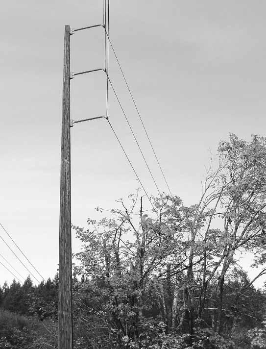
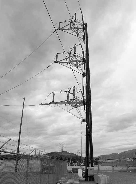
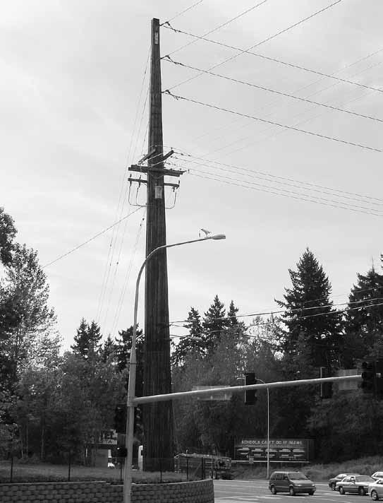
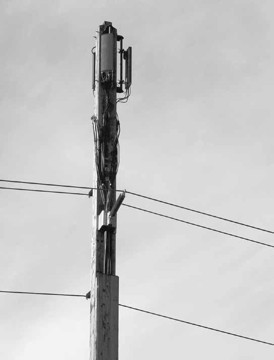
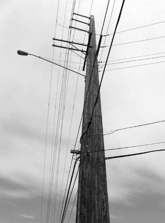
22 21 A few examples of laminated wood poles in use.
23 22
24 Corporate Headquarters: PO Box 1496, Tacoma, WA Phone: Fax: FLPC1110
Reinforced Soil Retaining Walls-Design and Construction
 Lecture 32 Reinforced Soil Retaining Walls-Design and Construction Prof. G L Sivakumar Babu Department of Civil Engineering Indian Institute of Science Bangalore 560012 Example calculation An 8 m high
Item 404 Driving Piling
 Item Driving Piling 1. DESCRIPTION Drive piling. 2. EQUIPMENT 2.1. Driving Equipment. Use power hammers for driving piling with specified bearing resistance. Use power hammers that comply with Table 1.
25 year warranty! Columns Are Available in Common Sizes: Widths: 3-1/2, 5-7/16, 5-1/2 and 7 Depths: 3-1/2, 5-1/2 and 7
 The OUTSIDER TM the finest pressure-treated glulam beams and columns engineered for building outdoors The Outsider beams and columns are made of Southern Yellow Pine and then pressure treated to resist
REPORT GEO-TECHNICAL INVESTIGATION FOR THE PROPOSED BLOCK-7 SUB-STATION SY NO-225, NEAR RAYACHERLU VILLAGE
 REPORT ON GEO-TECHNICAL INVESTIGATION FOR THE PROPOSED BLOCK-7 SUB-STATION SY NO-225, NEAR RAYACHERLU VILLAGE CLIENT: KARNATAKA SOLAR POWER DEVELOPMENT CORPORATION BANGALORE 0 GEO-TECHNICAL INVESTIGATION
Anchor Component Material Standard Mechanical Properties
 SECTION 4.1 PAGE 1 / 5 l description The UCAN sleeve anchor is a light-medium duty anchor ideal for applications in concrete, hollow block and brick. It is a mechanical expansion anchor assembled with
REPORT GEO-TECHNICAL INVESTIGATION FOR THE PROPOSED BLOCK-1 SUB-STATION SY NO-44, NEAR KYATAGANACHERLU VILLAGE
 REPORT ON GEO-TECHNICAL INVESTIGATION FOR THE PROPOSED BLOCK-1 SUB-STATION SY NO-44, NEAR KYATAGANACHERLU VILLAGE CLIENT: KARNATAKA SOLAR POWER DEVELOPMENT CORPORATION BANGALORE 0 GEO-TECHNICAL INVESTIGATION
Pole Foundation Design with Spreadsheet
 PDHonline Course S235 (1 PDH) Pole Foundation Design with Spreadsheet Instructor: John W. Andrew, PE 2012 PDH Online PDH Center 5272 Meadow Estates Drive Fairfax, VA 22030-6658 Phone & Fax: 703-988-0088
TOLL FREE: SIZING ( )
") Headquarters 915 Oberlin Rd. SW P.O. Box 810 Massillon, OH 44648 Tel: 330-837-4203 Southern Facility 7560 Industrial Highway P.O. Box 10157 Macon, GA 31297 Tel: 478-781-8725 WWW.MIDWESTERNIND.COM TOLL
Headquarters 915 Oberlin Rd. SW P.O. Box 810 Massillon, OH 44648 Tel: 330-837-4203 Southern Facility 7560 Industrial Highway P.O. Box 10157 Macon, GA 31297 Tel: 478-781-8725 WWW.MIDWESTERNIND.COM TOLL
6.0 ENGINEERING. Build Anything Better. REPRINTED 2017
 6.0 ENGINEERING TABLE OF CONTENTS 6.1 U.S. ENGINEERING ANALYSIS REPORT... P. 6-3 BELOW-GRADE WALL REINFORCEMENT TABLES... P. 6-5 ABOVE-GRADE WALL REINFORCEMENT TABLES.. P. 6-21 LINTEL REINFORCEMENT TABLES...P.
PUSH PIER SYSTEMS STABILITY. SECURITY. INTEGRITY. Push Pier Systems PN #MBPPT
 PUSH PIER SYSTEMS STABILITY. SECURITY. INTEGRITY. PN #MBPPT Push Pier Systems About Foundation Supportworks is a network of the most experienced and knowledgeable foundation repair and new construction
3. Types of foundation
 Foundation Engineering CE 48. Types of foundation & foundation materials Contents Introduction Shallow Foundations Deep Foundations Introduction Why different types of? General types of Introduction Why
SLIDE RAIL INSTALLATION GUIDE MANUFACTURE S TABULATED DATA
 SLIDE RAIL INSTALLATION GUIDE MANUFACTURE S TABULATED DATA 3330 S. Sam Houston Pkwy Houston, Texas 77047 (713)943-0750 USA Toll Free 1-800-231-6662 Fax (713)943-8483 Www.speedshore.com PRINTED IN U.S.A.
computed using Equation 3-18 by setting the 2nd term equal to 0 and K A equal to K o and using the pressure distribution as shown in Figure 3-23.
 computed using Equation 3-18 by setting the 2nd term equal to 0 and K A equal to K o and using the pressure distribution as shown in Figure 3-23. (2) For the resisting side, passive pressure theory indicates
l DESCRIPTION l FEATURES l LIMITATIONS l TYPICAL APPLICATIONS l MATERIAL SPECIFICATIONS TECHNICAL MANUAL SECTION 2.3 PAGE 1 / 6
 www.ucanfast.com TECHNICAL MANUAL SECTION 2.3 PAGE 1 / 6 l DESCRIPTION The UCAN WAG anchor is a fully threaded torque controlled expansion anchor assembled with a three segment expansion clip. All parts
Applications of trigonometry
 Applications of trigonometry This worksheet and all related files are licensed under the Creative Commons Attribution License, version 1.0. To view a copy of this license, visit http://creativecommons.org/licenses/by/1.0/,
Formation level = m. Foundation level = m. Height of the wall above the Ground Level = 7.42 m
 DESIGN OF RETAINING WALL INTRODUCTION: This wall is designed for active earth pressure and live load surcharge pressure The loads for the purpose of design are calculated per meter length of wall. BASIC
1) INTRODUCTION 2) THE UNFAIR ADVANTAGE
 INTRODUCTION 2) THE UNFAIR ADVANTAGE") 1 1) INTRODUCTION 2) THE UNFAIR ADVANTAGE and Stingray earth anchors are driven tipping plate soil anchors for reaction of tensile loads. anchors have ultimate capacities up to 20 tons, and Stingray anchors
1 1) INTRODUCTION 2) THE UNFAIR ADVANTAGE and Stingray earth anchors are driven tipping plate soil anchors for reaction of tensile loads. anchors have ultimate capacities up to 20 tons, and Stingray anchors
UNIT-I SOIL EXPLORATION
 SIDDHARTH GROUP OF INSTITUTIONS :: PUTTUR Siddharth Nagar, Narayanavanam Road 517583 QUESTION BANK (DESCRIPTIVE) Subject with Code : Geotechnical Engineering - II (16CE127) Year & Sem: III-B.Tech & II-Sem
WEDGE-ALL Wedge Anchors
 WEDGE-ALL Wedge Anchors The Wedge-All wedge anchors are a non-bottom bearing, wedge-style expansion anchor for use in solid concrete or grout-fi lled masonry. A one-piece clip ensures uniform holding capacity
CHEMICAL. Straight cut rod is provided in the materials listed below and includes nuts / washers.
 161 STRAIGHT CUT ROD Straight cut rod is provided in the materials listed below and includes nuts / washers. Straight Rod 22-1/2 Bent Rod A 307 THREADED ANCHOR ROD, ZINC PLATED (ASTM B633, CLEAR CHROMATE)
PACIFIC SHORING, LLC ALUMINUM SHORING PRODUCTS PSH HEAVY DUTY HYDRAULIC WALER RAIL SYSTEM. TABULATED DATA Effective December 10, 2013
 1 HEAVY DUTY HYDRAULIC WALER RAIL SYSTEM Effective December 10, 2013 PSH 265 Roberts Avenue Santa Rosa, Ca. 95407 (707) 575-9014 Construction Engineering Resource 1837 Wright Street Santa Rosa, Ca. 95404
PACIFIC SHORING, LLC ALUMINUM SHORING PRODUCTS HEAVY DUTY HYDRAULIC WALER RAIL SYSTEM. TABULATED DATA Effective August 25, 2015
 1 HEAVY DUTY HYDRAULIC WALER RAIL SYSTEM Effective August 25, 2015 PSH 265 Roberts Avenue Santa Rosa, Ca. 95407 (707) 575-9014 Construction Engineering Resource 1837 Wright Street Santa Rosa, Ca. 95404
TZ WEDGE ANCHOR FOR CRACKED AND UNCRACKED CONCRETE
 www.ucanfast.com TECHNICAL MANUAL SECTION 2.2 PAGE 1 / 10 ä DESCRIPTION UCAN TZ torque controlled mechanical expansion wedge anchors have a Category 1 classification. They are used to resist static, wind
Sub-Base Assembly For Type-ML 32 & VR-1 Step Voltage Regulator Single-Phase Liquid-Filled Part # GEK 35171
 Transformer Business Department Regulator & Inductive Products Sub-Base Assembly For Type-ML 32 & VR-1 Step Voltage Regulator Single-Phase Liquid-Filled Part # GEK 35171 Last Update 11-19-2013 Tom Dauzat,
CONE PENETRATION TESTS
 February 25, 2015 John Doe, P.E. Acme Engineering and Testing 1234 Test Avenue, Suite 204 Lake Wales, FL 33853 Re: Sample CPT Soundings Dear Mr. Doe, Direct Push Services, LLC (DPS) was retained by Acme
INSTITUTE OF AERONAUTICAL ENGINEERING (Autonomous) Dundigal, Hyderabad
 Dundigal, Hyderabad") INSTITUTE OF AERONAUTICAL ENGINEERING (Autonomous) Dundigal, Hyderabad - 500 043 CIVIL ENGINEERING Tutorial Question Bank Name : FOUNDATION ENGINEERING Code : A60126 Class : III B. Tech II Semester Branch
INSTITUTE OF AERONAUTICAL ENGINEERING (Autonomous) Dundigal, Hyderabad - 500 043 CIVIL ENGINEERING Tutorial Question Bank Name : FOUNDATION ENGINEERING Code : A60126 Class : III B. Tech II Semester Branch
"RIGGING SAFETY IN CONSTRUCTION ENVIRONMENTS"
 PRESENTER'S GUIDE "RIGGING SAFETY IN CONSTRUCTION ENVIRONMENTS" Part of the "CONSTRUCTION SAFETY KIT" Series Quality Safety and Health Products, for Today...and Tomorrow OUTLINE OF MAJOR PROGRAM POINTS
HARD COPY UNCONTROLLED Ergon Energy Corporation Ltd ABN
 CONSTRUCTION DWG No.CONSTRUCTION DWG No. Bollard Construction Codes 5--2- CB - - S CB - - S CB - - U CB - - U CB - - 2S CB - - 2S 00kN Stayed Bollard - Material List 00kN Stayed Bollard - Construction
LoneStar Fiberglass Pools. Do-It-Yourself. Installation Manual
 LoneStar Fiberglass Pools Do-It-Yourself Installation Manual Chris 1/3/2008 Do-It-Yourself The installation of a LoneStar Fiberglass pool is a much simpler task than most people think. What is important
COMPFIRE CCFT-FP_550_55_ September 2010 Fin Plate Connection to Circular Concrete-Filled Tube Test Result
 Reaction Frame Macalloy Bars Camera 3 Support Beam α Oven Bar Camera 2 Link Bar Camera 1 Tested Connection Jack Bar Electrical Furnace Reaction Frame Load Jack v2_5 April 2011 1 Oven Bar Link Bar View
INSTITUTE OF AERONAUTICAL ENGINEERING (Autonomous) Dundigal, Hyderabad CIVIL ENGINEERING TUTORIAL QUESTION BANK
 Dundigal, Hyderabad CIVIL ENGINEERING TUTORIAL QUESTION BANK") INSTITUTE OF AERONAUTICAL ENGINEERING (Autonomous) Dundigal, Hyderabad - 00 04 CIVIL ENGINEERING TUTORIAL QUESTION BANK Course Name Course Code Regulation Course Structure Course Coordinator Course Faculty
INSTITUTE OF AERONAUTICAL ENGINEERING (Autonomous) Dundigal, Hyderabad - 00 04 CIVIL ENGINEERING TUTORIAL QUESTION BANK Course Name Course Code Regulation Course Structure Course Coordinator Course Faculty
Submittal / Substitution Request
 Submittal / Substitution Request SUBMITTED TO: To: Firm: Project: Submitted Product: SIMPSON STRONG-TIE WEDGE-ALL WEDGE ANCHOR Specified Product: Section: Page: Detail/Sheet No.: Description of Application:
Suction anchor foundations for tension and taut leg floaters in deep waters. Tension Leg Platform. Taut Leg Platform. upper chain. risers.
 Case history: Soil investigation for offshore suction anchors anchor foundations for tension and taut leg floaters in deep waters Alternative anchors for floating structures pile Over last 5 - years anchoring
Soma Wind Generators
 Soma Wind Generators 13M WINH TOWER INSTALLATION MANUAL ERTIFIED to AS4100 Steel Structures ode AS3995 (1994) Design of Steel Lattice Towers and Masts AS1170.2 (1989) SAA Wind Loading Manufactured by SOMA
GENERAL GUIDELINES FOR PROPER RIGGING PRACTICES AND INSPECTION & REMOVAL CRITERIA FOR SLINGS PER OSHA
 GENERAL GUIDELINES FOR PROPER RIGGING PRACTICES AND INSPECTION & REMOVAL CRITERIA FOR SLINGS PER OSHA 1910.184 SAFE OPERATING PRACTICES -.Whenever any sling is used, the following practices shall be observed:
MICHIGAN DEPARTMENT OF TRANSPORTATION 6" X 8" (NOMINAL POST) 3-1/2" DIA. 2 HOLES TAPERED HARD WOOD WEDGES (HARDWOOD WEDGE
 3-1/2 DIA. 2 HOLES TAPERED HARD WOOD WEDGES (HARDWOOD WEDGE") X (NOMINAL POST) 1-1/ DIA. 2 HOLES X 8" (NOMINAL POST) 3-1/ DIA. 2 HOLES TAPERED HARD WOOD WEDGES (HARDWOOD WEDGE TO BE OAK, MAPLE OR OTHER APPROVED DENSE HARDWOODS) TO HOLD POST IN A STABLE POSITION AFTER
X (NOMINAL POST) 1-1/ DIA. 2 HOLES X 8" (NOMINAL POST) 3-1/ DIA. 2 HOLES TAPERED HARD WOOD WEDGES (HARDWOOD WEDGE TO BE OAK, MAPLE OR OTHER APPROVED DENSE HARDWOODS) TO HOLD POST IN A STABLE POSITION AFTER
On the Use of Pickets and Flukes as Snow Anchors
 On the Use of Pickets and Flukes as Snow Anchors ART FORTINI Sierra Madre Search & Rescue International Technical Rescue Symposium Denver, CO November 2002 Pickets Placements Traditional vertical Horizontal
Introduction of world construction methods and trends. Franz-Werner Gerressen, Head of Method Development, Tokyo,
 Introduction of world construction methods and trends Franz-Werner Gerressen, Head of Method Development, Tokyo, 2017-11-29 1 Introduction of world construction methods and trends Outline Single Pass Piling
Originally Issued: 10/08/2010 Revised: 10/27/2017 Valid Through: 10/31/2018
 ITW BUILDING COMPONENTS GROUP INC. ITW ALPINE HANGERS AND ANCHORS CSI Section: 06 05 23 Wood, Plastic and Composite Fastenings 1.0 RECOGNITION ITW Alpine Hangers and Anchors recognized in this report has
BOUNDARY Deer & Perimeter Fence
 Three-Part Specifications - Copyright 2015 - Nixalite of America Inc BOUNDARY Deer & Perimeter Fence Includes specifications for: BOUNDARY Lightweight, Standard, Extra Tall, Extra Strength and Maximum
SPOOLER INSTRUCTIONS. STEP 12 If you are going to paint your posts, that should be done at this time.
 STEP 4 Starting where you marked the end post location, move down your fence line 6 feet and make another mark. This mark is where your second upright post will be installed. Continuing down the fence
Hardened Steel Washers
 USS (Type A Wide) Flat Washers Hardened Steel Washers Grade 8 S.A.E. Dimensions American Standard Lbs. Per No./Pcs. Gauge M Pcs. Per Lb. 3/16 9/16 1/4 18 (3/64) 2.8 361 1/4 3/4 5/16 16 (1/16) 6.7 149 5/16
LiftAlloy TM Chain Slings
 LiftAlloy TM LiftAlloy CHAIN SLING BASICS Lift-All chain slings meet or exceed all OSHA, ASME B30.9 and NACM standards and regulations LiftAlloy chain slings, available in grade 00 for 7/32" through 3/4",
pvc well casing & drop pipe
 C e r t a i nte e d pvc well casing & drop pipe P V C We l l P r o d u c t s Sure Fit PVC well casing and drop pipe have gained broad acceptance since their introduction almost 40 years ago. Today, due
Design Data 22M. Flotation of Circular Concrete Pipe. w w I = w - x 1000 (3) (SG x 1000)
 (SG x 1000)") Design Data M Flotation of Circular Concrete Pipe There are several installation conditions where there is the possibility that concrete pipe may float even though the density of concrete is approximately.4
Design Data M Flotation of Circular Concrete Pipe There are several installation conditions where there is the possibility that concrete pipe may float even though the density of concrete is approximately.4
TANDEM plus BLUMOTION 569F/569A installation instructions
 TANDEM plus 569F/569A installation instructions inside Heavy duty full extension concealed runners Basic components Locking devices Runners New side adjustment New rear side adjustment Rotate side adjustment
SOIL ANCHORS ETSAB/UPC J.Llorens - ETSAB/UPC PASSIVE ANCHORS - ANTECEDENTS
 SOIL ANCHORS ignasi.llorens@upc.edu ETSAB/UPC - 2013 PASSIVE ANCHORS - ANTECEDENTS Antecedents of passive anchors can be found in Nature. Roots feed plants and provide uplift resistance against the wind
Outlet Structures T-12
 Description This section provides guidance and details for outlet structures for use primarily with BMPs utilizing sedimentation, (i.e., extended detention basins (EDBs), retention ponds, and constructed
Mechanical Anchoring Systems HDA Undercut Anchor Product description. HDA-P Undercut Anchor Pre-Set Type
 Mechanical Anchoring Systems 3.3 3.3.1 HDA Undercut Anchor 3.3.1.1 Product description The Hilti HDA undercut anchor is a heavy-duty mechanical anchor with carbide-tipped undercut segments used to perform
Roughneck TM Mesh Slings
 Roughneck TM Slings ROUGHNECK WIRE MESH SLINGS Widely used in metalworking shops and steel warehouses where loads are abrasive, hot or tend to cut web slings Features and Benefits Promotes Safety Steel
Low Wind High Yields Series
 Low Wind High Yields Series Wind Turbines USER S MANUAL Introduction Low Wind High Yields Series rotor blades apply the latest advanced thermoplastic engineering and are manufactured by precision injection
MoBiLe CrAnes. surelift. B y W i r e r o p e i n d u s t r i e s. tower CrAnes. port CrAnes
 MoBiLe CrAnes tower CrAnes overhead CrAnes port CrAnes 004-14-201-WR203-06/00 Printed in Canada on Recycled Paper performance series performance series ropes For MuLti-purpose AppLiCAtions Backed by over
Proof load is the load applied in performance of a proof test. Proof test is a nondestructive tension test performed by the sling manufacturer or an
 1910.184 Slings (a) Scope. This section applies to slings used in conjunction with other material handling equipment for the movement of material by hoisting, in employments covered by this part. The types
Side-of-Pole Mount for 1 Module (SPM1) For Module Types A & B
 For Module Types A & B") Side-of-Pole Mount for 1 Module (SPM1) For Module Types A & B ASSEMBLY INSTRUCTIONS step-by-step assembly and installation Version 1, Rev A PCN 080311-2 SP3363-1 Side-of-Pole Mount for 1 Module (SPM1)
Side-of-Pole Mount for 1 Module (SPM1) For Module Types A & B ASSEMBLY INSTRUCTIONS step-by-step assembly and installation Version 1, Rev A PCN 080311-2 SP3363-1 Side-of-Pole Mount for 1 Module (SPM1)
Shoreline Erosion Control Failures and How To Avoid Them
 2008 Illinois Lake Management Association Shoreline Erosion Control Failures and How To Avoid Them by: Hank Sutton, President, Lake Rip Rap, Inc. www.lakeriprap.com - www.macoupinboats.com Setting the
Premium PowerPoint Presentation. Rigging Review
 Premium PowerPoint Presentation Rigging Review Chapter 1 Hoisting Safety Review: What about the CG Symmetrical vs. Asymmetrical Balanced and Unbalanced Lifting Lug Hooks Angle Deformation Safety Gates
Originally Issued: 10/08/2010 Revised: 10/30/2015 Valid Through: 10/31/2016
 EVALUATION SUBJECT: ITW ALPINE HANGERS AND ANCHORS REPORT HOLDER: ITW Building Components Group Inc. 13825 W. Business Center Dr. Unit A Lake Forest, IL 60045 (800) 521-9790 www.alpineitw.com CSI Division:
ITEM 400 STRUCTURAL EXCAVATION AND BACKFILL
 AFTER MARCH 1, 2012 ITEM 400 STRUCTURAL EXCAVATION AND BACKFILL 400.1 Description. This item shall govern for all excavation required for the construction of all structures, except pipe or box sewers for
Heavy Equipment & Rigging Specialist Training
 Heavy Equipment & Rigging Specialist Training Module 1 Unit 4: Intro to Rigging May08 1 Key Points Review of Exercise Goals Discuss Rigging Components Language of Crane Signals Review Anchor Installation
Photo Coming. Utility Anchors. macleanpower.com
 Photo Coming Utility Anchors macleanpower.com Utility Anchors MPS Utility Anchors MacLean Power Systems has served the utility anchor market for over 90 years. With a rich history of quality, innovation
drilltech land drilling pipelining B y W i r e r o p e i n d u s t r i e s
 offshore production drilltech offshore drilling land drilling pipelining 004-14-201-WR203-06/00 Printed in Canada on Recycled Paper cushion 6 cushion 6 ropes For drilling applications The oil and gas industry
COLUMNS. Treated Glulam Column 1.9E Laminated Column Architectural Glulam Column
 COLUMNS Treated Glulam 1.9E Laminated Architectural Glulam Glulam: The Builder s Choice Glued laminated timber, or glulam, combines the structural values and product consistency of engineered wood, with
Driveway Design Criteria
 Design Manual Chapter 5 - Roadway Design 5L - Access Management 5L-4 Driveway Design Criteria A. General For efficient and safe operations, access drives and minor public street intersections can be improved
Shade Sails - Installation Tips
 Shade Sails - Installation Tips Shade Sails Installation Suggestions Design and Layout: Shade Sails can be mounted in a variety of ways. Sails can be mounted flat or with high and low points. A flat sail
NEXT GENERATION FLEX FENCE
 NEXT GENERATION FLEX FENCE Area To Be Fenced.. With Next Generation Flex Fence any post that is not in a straight line with another post must be braced. Layout your fence installation. Determine all end
Lesson 8 Piles Bearing & Acceptance Transcript. Welcome to the Pile Driving Inspector Course. This is Lesson 8 Piles Bearing & Acceptance.
 Lesson 8 Piles Bearing & Acceptance Transcript Welcome to the Pile Driving Inspector Course. This is Lesson 8 Piles Bearing & Acceptance. To begin, select the start button or press Shift+N on your keyboard.
SAFETY JOURNAL FOR GIPFEL WEDGE ROCK ANCHOR BOLTS
 SAFETY JOURNAL FOR GIPFEL WEDGE ROCK ANCHOR BOLTS NOTE: Here we are only talking about the wedge type expansion bolts. How do rock anchors fail? A rock anchor assembly mainly comprises of a Hanger and
HARDPOINT ASESSMENT FOR SUSPENSION BONDAGE
 HARDPOINT ASESSMENT FOR SUSPENSION BONDAGE By Jim Duvall w Jim Duvall 2011 COURSE GOALS Will that hold me? Why should you worry? How much should you worry? Who pays the price of failure? w Jim Duvall 2011
STRAIGHT POLE TENSIONED BATTING TUNNEL POLE LAYOUT
 STRAIGHT POLE TENSIONED BATTING TUNNEL POLE LAYOUT SOFTBALL: 55' x 14' Nets BASEBALL: 75' x 14' Nets No. 330155 No. 330175 63'-0" 83'-0" SINGLE NET 1 1 No. 330255 No. 330275 63'-0" 83'-0" DOUBLE NET No.
SPEED SHORE MANUFACTURER S TABULATED DATA "MHS" MODELS. STEEL MANHOLE SHIELDS 4 Single Wall 4 Double Wall 4 Double Wall with Cut-Outs
 SPEED SHORE MANUFACTURER S TABULATED DATA "MHS" MODELS STEEL MANHOLE SHIELDS 4 Single Wall 4 Double Wall 4 Double Wall with Cut-Outs January 01, 2005 3330 S. SAM HOUSTON PKWY E. HOUSTON, TEXAS 77047 Tel:
coolaroo.com Protection all year round Installing your new Coolaroo all weather sail is simple, following our step-by-step instructions.
 Protection all year round Installing your new Coolaroo all weather sail is simple, following our step-by-step instructions. Features Provides 100% UV block Water resistant M ade with UV stabilised knitted
TAO Safety Policy No. HS-5.1 Page 1 of 15 Revision No. 2 Revision Date: July 19, 2005
 TAO Safety Policy No. HS-5.1 Page 1 of 15 Revision No. 2 1.0 OVERVIEW This safety policy provides guidance for conducting trenching and excavation activities at project sites. Emphasis is placed on sloping
h o l l o w poles for foundat i o n s
 TTT Products Limited July 2017. 1 of 6 The MultiPole advantage The TTT MultiPole is an incredibly versatile pole due to its unique hollow core. The MultiPole is a multifunctional pole suitable for structural
LOAD HUGGER CARGO CONTROL
 Hugger BASICS Lift-All Hugger cargo control and load securement products are of the highest quality. They offer the van and flatbed operator a wide variety of options to meet Department of Transportation
WEBMASTER 00 SLINGS master 00 Polyester Slings Hardware Slings (TYPES U, AND ) Standard duty master 00 is designed for less frequent, light duty servi
 Standard duty master 00 is designed for less frequent, light duty servi") Best in Abrasion Resistance Available in two strength classes, all Dura- slings feature premium abrasive resistant yarns covering all surfaces, for extended sling life and long term value. Dura- Features,
Best in Abrasion Resistance Available in two strength classes, all Dura- slings feature premium abrasive resistant yarns covering all surfaces, for extended sling life and long term value. Dura- Features,
Seattle City Light Construction Management
 Seattle City Light Construction Management Submittal Transmittal & Response Shaded areas are for SCL use only Submittal Number: 0102.1 Date: 10/26/2015 (Contractor: give each submittal transmittal a consecutive
HEAVY DUTY H.S. DISCUS CAGE NET POLE NET POLE INSTALLATION
 901020 - HEAVY DUTY H.S. DISCUS CAGE NET POLE NET POLE INSTALLATION www.gillathletics.com 800-637-3090 Install the pipe cap (PCAP00158002) at the top of the net pole. Install net pole pulley (73210042)
APPENDIX A. F107 & 380 Lines OYSTER RIVER DURHAM, NH
 APPENDIX A F107 & 380 Lines OYSTER RIVER DURHAM, NH 1. The design and proposed construction of this crossing is shown on the attached PSNH Transmission Business Drawing entitled DOUBLE CKT F107 & 380 BETWEEN
Aluminum Sheeting Guide (ASG)
") Tabulated Data Aluminum Sheeting Guide (ASG) February 2016 Copyright, U.S.A.,Griswold Machine & Eng., 2016 594 Mendon Road, Union City, MI 49094 (800) 248 2054 Fax: (517) 741 7483 CAUTION EXCAVATION PROCEDURES
Tabulated Data Aluminum Sheeting Guide (ASG) February 2016 Copyright, U.S.A.,Griswold Machine & Eng., 2016 594 Mendon Road, Union City, MI 49094 (800) 248 2054 Fax: (517) 741 7483 CAUTION EXCAVATION PROCEDURES
VSL MINING & TUNNELING SYSTEMS VSL. mining and tunneling
 VSL MINING & TUNNELING SYSTEMS VSL mining and tunneling VSL Mining & Tunneling Bolt systems VSL offers three type of bolting system for the mining & Tunnelling industry VSL-S Solid Threaded bolts. Continuous
"STEEL FRAMED" ALUMINUM PANEL SHIELDS
 "STEEL FRAMED" ALUMINUM PANEL SHIELDS MANUFACTURE S TABULATED DATA 3330 S. Sam Houston Pkwy Houston, Texas 77047 (713)943-0750 USA Toll Free 1-800-231-6662 Fax (713)943-8483 Www.speedshore.com PRINTED
Construction Dewatering
 Construction Dewatering Introduction The control of groundwater is one of the most common and complicated problems encountered on a construction site. Construction dewatering can become a costly issue
Dean Pump Self-Priming Chemical Process Pumps
 Bulletin C 1.2.34.7 Dean Pump Self-Priming Chemical Process Pumps php Series HEAD CAPACITY RANGE CHARTS php Self Primer - 2 Pole 3500 RPM 500 CAPACITY M 3 /HR 2900 RPM 50 HERTZ 25 50 75 125 150 400 TOTAL
 TYPE: LSF - LIFTING STUD FOOT ANCHOR DESCRIPTION: The design of the anchor means no additional reinforcement is required as the forces are transferred into the concrete from the design of the foot of the
Side-of-Pole Mount for 1 Module (SPM1) For Module Type C
 For Module Type C") Module Type Width Length C 22-27 56-63 Side-of-Pole Mount for 1 Module (SPM1) For Module Type C ASSEMBLY INSTRUCTIONS step-by-step assembly and installation Version 1, Rev A PCN 022212-1 Side-of-Pole Mount
Module Type Width Length C 22-27 56-63 Side-of-Pole Mount for 1 Module (SPM1) For Module Type C ASSEMBLY INSTRUCTIONS step-by-step assembly and installation Version 1, Rev A PCN 022212-1 Side-of-Pole Mount
BARRIER OFFSET 0" A 6" 6" A 12" 12" A 26" A 26" 3A OR 4A L OR S * ** L OR S L OR S
 ACCEPTABLE (TCB) TYPES AND ANCHORING DETAILS BASED ON UNDERLYING SURFACE TYPE AND BARRIER OFFSET FROM DROP-OFF BARRIER OFFSET UNDERLYING SURFACE 0" A 6" 6" A 12" 12" A 26" A 26" TCB TYPE DETAIL TCB TYPE
STEEL TRENCH SHIELDS DW MODELS
 STEEL TRENCH SHIELDS DW MODELS 3330 S. SAM HOUSTON PKWY E. HOUSTON, TEXAS 77047 Phone: 713.943.0750 Toll Free: 800.231.6662 Fax: 713. 943.8483 COPYRIGHT, U.S.A., SPEED SHORE CORPORATION, 2009 April 16,
Row Marker OEM /
 IMPORTANT: Your new row marker is designed to attach to the Troy-Bilt Hiller-Furrower attachment. If you don t have Hiller- Furrower, call us or visit www.troybilt.com to place an order: OEM-290-250 for
EVALUATION SUBJECT: SPUNSTRAND STANDARD AND INSULATED UNDERSLAB DUCTS
 ICC-ES Report ESR-1681 Reissued 12/2017 This report is subject to renewal 12/2018 EVALUATION SUBJECT: SPUNSTRAND STANDARD AND INSULATED UNDERSLAB DUCTS DIVISION: 23 00 00 HEATING, VENTILATING AND AIR CONDITIONING
DIVISION: 06--WOOD AND PLASTICS SECTION: Wood, Plastic and Composite Fastenings
 DIVISION: 06--WOOD AND PLASTICS SECTION: 060523 -- Wood, Plastic and Composite Fastenings REPORT HOLDER: ITW BUILDING COMPONENTS GROUP, INC. 2400 LAKE ORANGE DRIVE, SUITE 150 ORLANDO, FLORIDA 32837 (800)
CUT AND WEAR PROTECTION
 CUT AND WEAR PROTECTION Selection of Products protection products need to be used in applications where sling damage can occur. Cutting of synthetic slings during use is the number one cause of sling accidents.
FORESTRY TIRES FULL-LINE BROCHURE
 FORESTRY TIRES FULL-LINE BROCHURE BUILT TO PERFORM There s a simple rule in today s logging business: You can only make money when you keep the machines moving. Downtime will drain the profits out of
Design Project 2 Sizing of a Bicycle Chain Ring Bolt Set ENGR 0135 Sangyeop Lee November 16, 2016 Jordan Gittleman Noah Sargent Seth Strayer Desmond
 1 Design Project 2 Sizing of a Bicycle Chain Ring Bolt Set ENGR 0135 Sangyeop Lee November 16, 2016 Jordan Gittleman Noah Sargent Seth Strayer Desmond Zheng 2 Abstract This report will analyze our calculations,
Tension Cracks. Topics Covered. Tension crack boundaries Tension crack depth Query slice data Thrust line Sensitivity analysis.
 Tension Cracks 16-1 Tension Cracks In slope stability analyses with cohesive soils, tension forces may be observed in the upper part of the slope. In general, soils cannot support tension so the results
MANUAL OF HANDLING, TRANSPORTATION AND STORAGE OF ELECTRICAL CABLE REELS
 MANUAL OF HANDLING, TRANSPORTATION AND STORAGE OF ELECTRICAL CABLE REELS OBJECTIVE Establish conditions for the proper handling, transportation and storage of electric cable reels, in order to keep the
The installation of this kit must be performed by an authorized Honda riding mower dealer. These instructions are provided for dealer use.
 1. DEALER INSTALLATION INSTRUCTIONS The installation of this kit must be performed by an authorized Honda riding mower dealer. These instructions are provided for dealer use. FOLLOW THESE INSTRUCTIONS
For Review Only No Copying No Saving No Lending No Posting Online
 The following copyrighted samples are provided as a service for your review only. Copying, saving, lending, posting online or any general use of these files other than for the purpose provided is unlawful
List of Figures. List of Tables
 City of Columbia Engineering Regulations PART 19: SPECIFICATIONS FOR FENCING MATERIALS Table of Contents Paragraph Description Page No. 19.1 General 19-1 19.2 Construction Materials 19-1 List of Figures
provides an increased stiffness and strength compared with standard cee studs, resulting in lighter headers which require less labor to install.
 CURTAIN WALL SYSTEMS HEADER/SILL SOLUTIONS JAMSTUD HEADER/SILL ASSEMBLY VALUE delivers exceptional value when utilized as part of a header or sill assembly. s unique shape allows for the design and construction
Winchline n a box WINCH LINE SELECTION GUIDE. Wire Rope Winchlines are superior to most other winchlines found in the market place due to the
 Winchline n a box Wire Rope Winchlines are superior to most other winchlines found in the market place due to the eye) end terminations. Each eye is protected by a steel liner (thimble) to guard against