25 year warranty! Columns Are Available in Common Sizes: Widths: 3-1/2, 5-7/16, 5-1/2 and 7 Depths: 3-1/2, 5-1/2 and 7
|
|
|
- Jody Lamb
- 6 years ago
- Views:
Transcription

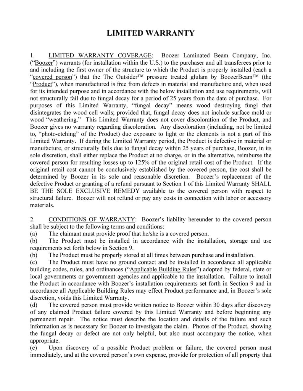
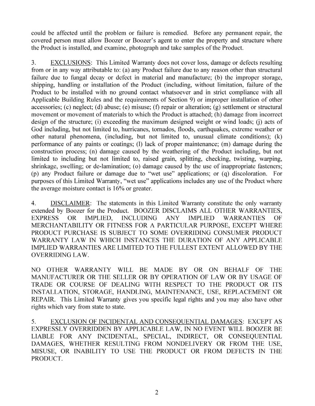
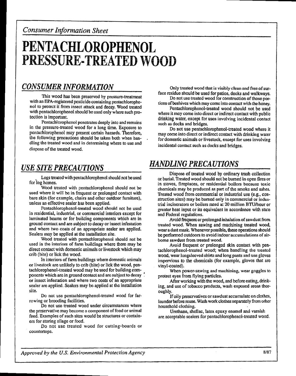
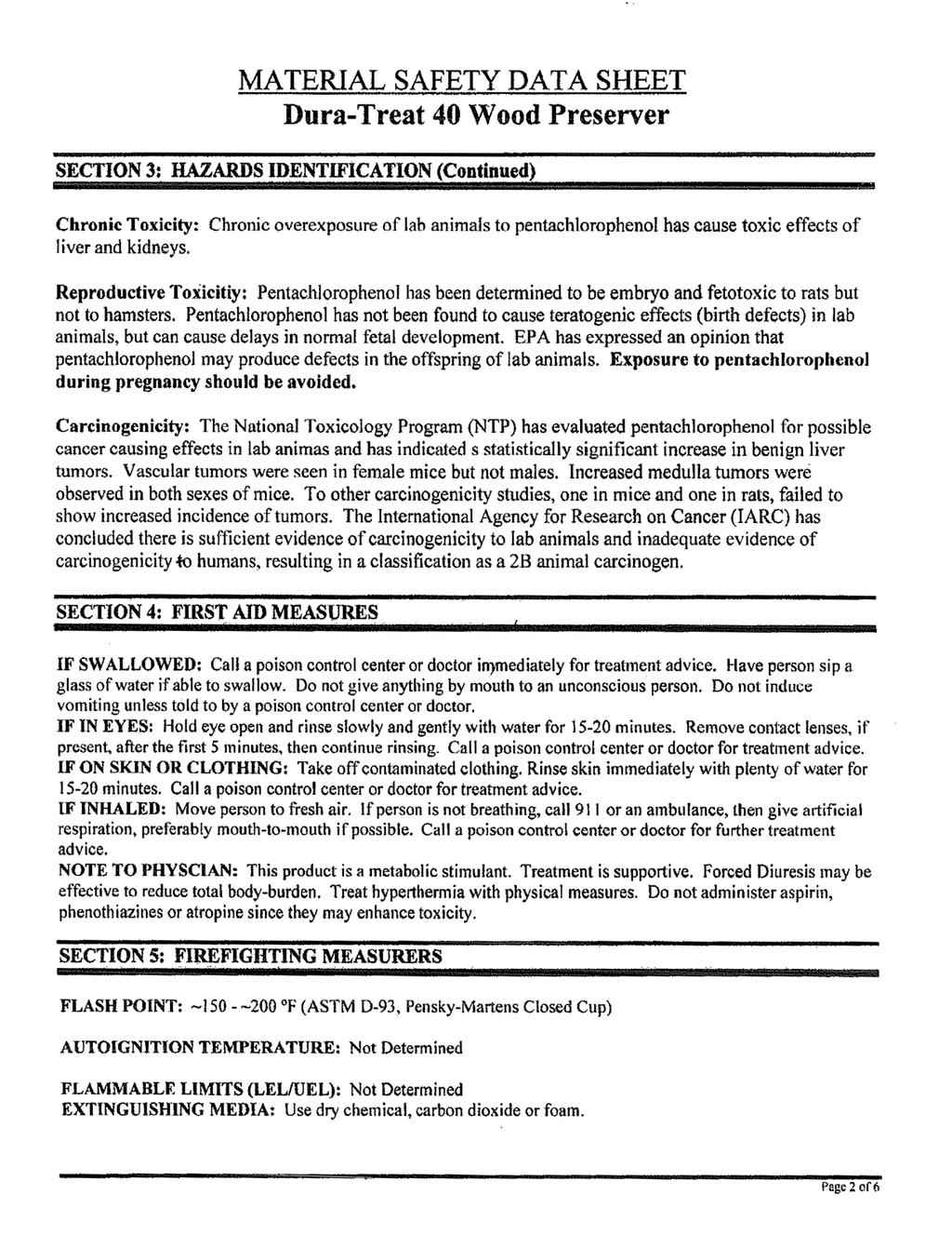
1 The OUTSIDER TM the finest pressure-treated glulam beams and columns engineered for building outdoors The Outsider beams and columns are made of Southern Yellow Pine and then pressure treated to resist rot and decay. Manufactured to match standard framing widths and depths make the Outsider ideal for decks, trellises, porches and balconies. The OUTSIDER is treated with Penta. The Outsider is treated with Penta, which contains solubized pentachlorophenol. Penta provides resistance to insects, decay, mold, mildew and bacterial growths. Pressure treatment of The Outsider is clean, nonswelling, non-leaching and non-corrosive. OUTSIDER Beams Beams are manufactured to a performance level of 24F/1.8E with a balanced layup, straight with no designated top or bottom, for easy installation. And of course, The Outsider is sized to match standard framing widths and depths. They may also be used in both wet-use and dry-use applications. Beams Are Available in Common Sizes: Widths: 3-1/2, 5-1/4, 5-7/16 and 5-1/2 Depths: 9-1/4, 9-1/2, 11-1/4, 11-7/8, 14, 16 and 18

2 OUTSIDER Columns Columns are manufactured to a combination #50/1.9E lay up and are ideal anywhere a post is needed for your application. Columns placed on a pier block are considered to be in a dry-use application, provided it never reached 16% or greater moisture content. The attached Table 1 should be used for these values. However, columns that have direct ground contact or are imbedded constitute a wet-use application and Table 2 applies. Columns Are Available in Common Sizes: Widths: 3-1/2, 5-7/16, 5-1/2 and 7 Depths: 3-1/2, 5-1/2 and 7 Recommended Applications The Outsider is the best engineered wood beam for building outdoors. Wet conditions are no problem. Moisture and decay-resistance helps protect the areas around hardware connections; however, field fabrication and trimming, hole drilling, and minor surface damage should be re-sealed with Penta (available at your local building supply store). Outsider beams and columns should not be used in marine applications such as docks, marinas and standing water conditions. What are Wet-use and Dry-use? Glulam products are often intermittently exposed to the elements. This is typically followed by drying. Even though the beam or column is exposed to the elements, it could be considered to be in a dry-use condition provided it never reached 16% or greater moisture content. In this situation, Table 1 capacity charts may be used. An application is considered wet-use if at anytime the moisture content reaches 16% or greater (see the chart below). These conditions necessitate the use of the Table 2 capacity chart. Due to The Outsider s exceptional strength and quality, use of wet-use tables (Table 2) is the most beneficial for more conservative design assurance. To retain an open-air moisture content of at least 16% (wet-use application), a beam must stay in a wet environment year-round, as illustrated at right. 25 year warranty!
3 Treated 2400Fb-1.8E-300Fv Southern Pine Glulam Roof Beams (lbf/ft) Snow Load (DRY USE) Load Duration Factor = 1.25, Fbx = 2,400 psi, Fvx = 300 psi, Ex = 1,800,000 psi 3-1/2-INCH WIDTH SPAN (ft) Depth (in.) / / / / /16-INCH WIDTH SPAN (ft) Depth (in.) / / / / Notes: (1) For preliminary design use only. Final design should include a complete analysis, including bearing stresses and lateral stability. (2) Span = simply supported beam. (3) Maximum deflection = L/180 under total load. Other deflection limits may apply. (4) Service condition = dry. (5) Tabulated values represent total loads and have taken the dead weight of the beam (assumed 37.5 pcf) into account. (6) Sufficient bearing length shall be provided at supports (7) Maximum beam shear is located at a distance from the supports equal to the depth of the beam. (8) Upper-right areas limited by deflection; lower-left areas limited by bending strength. June 15, 2015 Page 1 of 6
4 Treated 2400Fb-1.8E-300Fv Southern Pine Glulam Roof Beams (lbf/ft) Snow Load (WET USE) Load Duration Factor = 1.25, Fbx = 2,400 x 0.8 psi, Fvx = 300 x psi, Ex = 1,800,000 x psi 3-1/2-INCH WIDTH SPAN (ft) Depth (in.) / / / / /16-INCH WIDTH SPAN (ft) Depth (in.) / / / / Notes: (1) For preliminary design use only. Final design should include a complete analysis, including bearing stresses and lateral stability. (2) Span = simply supported beam. (3) Maximum deflection = L/180 under total load. Other deflection limits may apply. (4) Service condition = wet. (5) Tabulated values represent total loads and have taken the dead weight of the beam (assumed 52 pcf) into account. (6) Sufficient bearing length shall be provided at supports (7) Maximum beam shear is located at a distance from the supports equal to the depth of the beam. (8) Upper-right areas limited by deflection; lower-left areas limited by bending strength. June 15, 2015 Page 2 of 6
5 Treated 2400Fb-1.8E-300Fv Southern Pine Glulam Roof Beams (lbf/ft) Snow Load (DRY USE) Load Duration Factor = 1.15, Fbx = 2,400 psi, Fvx = 300 psi, Ex = 1,800,000 psi 3-1/2-INCH WIDTH SPAN (ft) Depth (in.) / / / / /16-INCH WIDTH SPAN (ft) Depth (in.) / / / / Notes: (1) For preliminary design use only. Final design should include a complete analysis, including bearing stresses and lateral stability. (2) Span = simply supported beam. (3) Maximum deflection = L/180 under total load. Other deflection limits may apply. (4) Service condition = dry. (5) Tabulated values represent total loads and have taken the dead weight of the beam (assumed 37.5 pcf) into account. (6) Sufficient bearing length shall be provided at supports (7) Maximum beam shear is located at a distance from the supports equal to the depth of the beam. (8) Upper-right areas limited by deflection; lower-left areas limited by bending strength. June 15, 2015 Page 3 of 6
6 Treated 2400Fb-1.8E-300Fv Southern Pine Glulam Roof Beams (lbf/ft) Snow Load (WET USE) Load Duration Factor = 1.15, Fbx = 2,400 x 0.8 psi, Fvx = 300 x psi, Ex = 1,800,000 x psi 3-1/2-INCH WIDTH SPAN (ft) Depth (in.) / / / / /16-INCH WIDTH SPAN (ft) Depth (in.) / / / / Notes: (1) For preliminary design use only. Final design should include a complete analysis, including bearing stresses and lateral stability. (2) Span = simply supported beam. (3) Maximum deflection = L/180 under total load. Other deflection limits may apply. (4) Service condition = wet. (5) Tabulated values represent total loads and have taken the dead weight of the beam (assumed 52 pcf) into account. (6) Sufficient bearing length shall be provided at supports (7) Maximum beam shear is located at a distance from the supports equal to the depth of the beam. (8) Upper-right areas limited by deflection; lower-left areas limited by bending strength. June 15, 2015 Page 4 of 6
7 2400Fb-1.8E-300Fv Southern Pine Glulam Floor Beams (lbf/ft) (DRY USE) Load Duration Factor = 1.0, Fbx = 2,400 psi, Fvx = 300 psi, Ex = 1,800,000 psi 3-1/2-INCH WIDTH SPAN (ft) Depth (in.) / / / / /16-INCH WIDTH SPAN (ft) Depth (in.) / / / / Notes: (1) For preliminary design use only. Final design should include a complete analysis, including bearing stresses and lateral stability. (2) Span = simply supported beam. (3) Maximum deflection = L/360 under live load, based on live/total load = 0.8. Where additional stiffness is desired or for other live/total load ratios, design for deflection must be modified per requirements. (4) Service condition = dry. (5) Tabulated values represent total loads based on live/total load = 0.8 and have taken the dead weight of the beam (assumed 37.5 pcf) into account. (6) Sufficient bearing length shall be provided at supports (7) Maximum beam shear is located at a distance from the supports equal to the depth of the beam. (8) Upper-right areas limited by deflection; lower-left areas limited by bending strength. June 15, 2015 Page 5 of 6
8 2400Fb-1.8E-300Fv Southern Pine Glulam Floor Beams (lbf/ft) (WET USE) Load Duration Factor = 1.0, Fbx = 2,400 x 0.8 psi, Fvx = 300 x psi, Ex = 1,800,000 x psi 3-1/2-INCH WIDTH SPAN (ft) Depth (in.) / / / / /16-INCH WIDTH SPAN (ft) Depth (in.) / / / / Notes: (1) For preliminary design use only. Final design should include a complete analysis, including bearing stresses and lateral stability. (2) Span = simply supported beam. (3) Maximum deflection = L/360 under live load, based on live/total load = 0.8. Where additional stiffness is desired or for other live/total load ratios, design for deflection must be modified per requirements. (4) Service condition = wet. (5) Tabulated values represent total loads based on live/total load = 0.8 and have taken the dead weight of the beam (assumed 52 pcf) into account. (6) Sufficient bearing length shall be provided at supports (7) Maximum beam shear is located at a distance from the supports equal to the depth of the beam. (8) Upper-right areas limited by deflection; lower-left areas limited by bending strength. June 15, 2015 Page 6 of 6
9 Allowable Axial Loads (Pounds) for Combination No. 50 Glulam Column (DRY USE) Side loads are not permitted. End loads are limited to a maximum eccentricity of either 1/6 column width or depth, whichever is worse. Effective Column Net Depth = 3-1/2 in. (3 lams) Net Depth = 4-1/4 in. (4 lams) Lamination Net Width = 3-1/2 in. Net Depth = 5-1/2 in. (4 lams) Net Depth = 7 in. (6 lams) Net Depth = 8-1/4 in. (6 lams) Length Load Duration Factor Load Duration Factor Load Duration Factor Load Duration Factor Load Duration Factor (ft) ,970 13,420 14,330 17,180 19,220 20,510 23,320 25,890 27,460 29,700 32,950 34,950 35,010 38,830 41, ,840 11,950 12,620 15,450 16,960 17,850 20,340 22,080 23,100 25,890 28,100 29,400 30,520 33,120 34, ,560 10,330 10,770 13,300 14,150 14,640 17,210 18,310 18,950 21,900 23,300 24,110 25,810 27,470 28, ,240 8,760 9,060 11,110 11,680 12,000 14,380 15,110 15,530 18,300 19,230 19,770 21,570 22,670 23, ,050 7,410 7,610 9,320 9,710 9,940 12,060 12,570 12,860 15,350 16,000 16,370 18,090 18,860 19, ,040 6,300 6,450 7,880 8,170 8,340 10,200 10,570 10,790 12,980 13,460 13,730 15,300 15,860 16, ,210 5,400 5,520 6,730 6,950 7,080 8,710 8,990 9,160 11,090 11,450 11,650 13,070 13,490 13, ,520 4,670 4,760 5,810 5,980 6,070 7,520 7,730 7,860 9,570 9,840 10,000 11,270 11,600 11, ,960 4,080 4,150 5,050 5,190 5,260 6,540 6,710 6,810 8,330 8,540 8,670 9,810 10,070 10, ,490 3,590 3,640 4,440 4,540 4,600 5,740 5,880 5,960 7,310 7,480 7,580 8,610 8,820 8, ,100 3,170 3,220 3,920 4,010 4,060 5,080 5,190 5,250 6,460 6,600 6,680 7,610 7,780 7,880 Notes: 1. The tabulated allowable loads apply only to one-piece glulam members made with all N1D14 laminations (Combination 50) without special tension laminations. 2. Applicable service conditions = dry 3. The tabulated allowable loads are based on simply axially loaded columns subjected to a maximum eccentricity of either 1/6 column width or 1/6 column depth, whichever is worse. For side loads, other eccentric end loads, or other combined axial and flexural loads, see 2015 NDS 4. The column is assumed to be unbraced, except at the column ends, and the effective column length is equal to the actual column length. 5. Design properties for normal load duration and dry-use service conditions: Compression parallel to grain (F c ) = 2,300 psi for 4 or more lams, or 1,700 psi for 2 or 3 lams. Modulus of elasticity (E) = 1.9 x 10 6 psi Flexural stress when loaded parallel to wide faces of lamination (F by ) = 2,300 psi for 4 or more lams, or 2,100 psi for 3 lams. Flexural stress when loaded perpendicular to wide faces of lamination (F bx ) = 2,100 psi for 2 lams to 15 in. deep without special tension laminations. Volume factor for F bx is in accordance with 2015 NDS. Size factor for F by is (12/d) 1/9, where d is equal to the lamination width in inches. June 1, 2015 Page 1 of 6
10 Allowable Axial Loads (Pounds) for Combination No. 50 Glulam Column (WET USE) Side loads are not permitted. End loads are limited to a maximum eccentricity of either 1/6 column width or depth, whichever is worse. Effective Column Net Depth = 3-1/2 in. (3 lams) Net Depth = 4-1/4 in. (4 lams) Lamination Net Width = 3-1/2 in. Net Depth = 5-1/2 in. (4 lams) Net Depth = 7 in. (6 lams) Net Depth = 8-1/4 in. (6 lams) Length Load Duration Factor Load Duration Factor Load Duration Factor Load Duration Factor Load Duration Factor (ft) ,250 10,400 11,140 13,370 15,020 16,060 18,040 20,290 21,590 23,170 25,820 27,470 27,300 30,430 32, ,490 9,410 9,970 12,200 13,460 14,230 16,140 17,630 18,510 20,540 22,430 23,560 24,210 26,440 27, ,600 8,270 8,660 10,720 11,470 11,900 13,870 14,840 15,400 17,660 18,890 19,590 20,810 22,260 23, ,650 7,100 7,360 9,050 9,540 9,820 11,710 12,350 12,710 14,910 15,720 16,180 17,570 18,520 19, ,740 6,050 6,230 7,630 7,970 8,170 9,880 10,320 10,570 12,570 13,130 13,450 14,810 15,470 15, ,940 5,170 5,300 6,470 6,720 6,860 8,380 8,700 8,880 10,660 11,070 11,310 12,570 13,050 13, ,270 4,440 4,540 5,540 5,730 5,830 7,170 7,410 7,550 9,130 9,440 9,610 10,760 11,120 11, ,720 3,850 3,920 4,790 4,930 5,010 6,200 6,380 6,490 7,890 8,120 8,260 9,290 9,570 9, ,260 3,360 3,420 4,170 4,290 4,350 5,400 5,550 5,630 6,870 7,060 7,160 8,100 8,320 8, ,880 2,960 3,010 3,660 3,760 3,810 4,740 4,860 4,930 6,040 6,190 6,270 7,110 7,290 7, ,560 2,620 2,660 3,240 3,320 3,360 4,200 4,290 4,350 5,340 5,460 5,530 6,290 6,440 6,520 Notes: 1. The tabulated allowable loads apply only to one-piece glulam members made with all N1D14 laminations (Combination 50) without special tension laminations. 2. Applicable service conditions = wet 3. The tabulated allowable loads are based on simply axially loaded columns subjected to a maximum eccentricity of either 1/6 column width or 1/6 column depth, whichever is worse. For side loads, other eccentric end loads, or other combined axial and flexural loads, see 2015 NDS 4. The column is assumed to be unbraced, except at the column ends, and the effective column length is equal to the actual column length. 5. Design properties for normal load duration and wet-use service conditions: Compression parallel to grain (F c ) = 2,300 x 0.73 psi for 4 or more lams, or 1,700 x 0.73 psi for 2 or 3 lams. Modulus of elasticity (E) = 1.9 x x 10 6 psi Flexural stress when loaded parallel to wide faces of lamination (F by ) = 2,300 x 0.8 psi for 4 or more lams, or 2,100 x 0.8 psi for 3 lams. Flexural stress when loaded perpendicular to wide faces of lamination (F bx ) = 2,100 x 0.8 psi for 2 lams to 15 in. deep without special tension laminations. Volume factor for F bx is in accordance with 2015 NDS. Size factor for F by is (12/d) 1/9, where d is equal to the lamination width in inches. June 17, 2015 Page 2 of 6
11 Allowable Axial Loads (Pounds) for Combination No. 50 Glulam Column (DRY USE) Side loads are not permitted. End loads are limited to a maximum eccentricity of either 1/6 column width or depth, whichever is worse. Effective Lamination Net Width = 5-1/2 in. Column Net Depth = 5-1/2 in. (4 lams) Net Depth = 7 in. (6 lams) Net Depth = 8-1/4 in. (6 lams) Net Depth = 9-5/8 in. (7 lams) Length Load Duration Factor Load Duration Factor Load Duration Factor Load Duration Factor (ft) ,760 42,840 46,150 49,420 56,300 60,810 58,990 67,330 72,820 69,400 79,320 85, ,880 40,390 43,280 47,710 54,040 58,140 57,350 65,140 70,210 67,790 76,940 82, ,680 37,530 39,950 45,610 51,260 54,840 54,950 61,180 65,070 64,110 71,370 75, ,220 34,370 36,300 43,100 47,380 49,960 50,800 55,840 58,880 59,260 65,140 68, ,570 31,050 32,520 39,290 42,590 44,520 46,310 50,190 52,470 54,030 58,560 61, ,870 27,780 28,900 35,400 37,880 39,320 41,720 44,650 46,340 48,680 52,090 54, ,270 24,750 25,610 31,680 33,560 34,650 37,330 39,560 40,840 43,560 46,150 47, ,890 22,060 22,740 28,290 29,760 30,600 33,340 35,070 36,070 38,900 40,920 42, ,770 19,710 20,250 25,300 26,470 27,140 29,820 31,190 31,990 34,790 36,390 37, ,910 17,680 18,120 22,690 23,640 24,180 26,750 27,860 28,500 31,200 32,500 33, ,280 15,910 16,280 20,430 21,210 21,660 24,080 25,000 25,520 28,090 29,160 29, ,860 14,390 14,690 18,470 19,110 19,490 21,760 22,530 22,970 25,390 26,280 26, ,610 13,060 13,320 16,760 17,300 17,610 19,750 20,390 20,760 23,040 23,790 24, ,520 11,900 12,120 15,260 15,730 15,990 17,990 18,530 18,850 20,990 21,620 21, ,550 10,880 11,070 13,950 14,350 14,580 16,440 16,910 17,180 19,190 19,730 20, ,700 9,980 10,150 12,800 13,140 13,340 15,090 15,490 15,720 17,600 18,070 18, ,940 9,190 9,330 11,780 12,080 12,250 13,880 14,230 14,430 16,200 16,600 16, ,270 8,490 8,610 10,870 11,130 11,280 12,820 13,120 13,300 14,950 15,310 15, ,670 7,860 7,970 10,070 10,290 10,420 11,860 12,130 12,290 13,840 14,150 14,330 Notes: 1. The tabulated allowable loads apply only to one-piece glulam members made with all N1D14 laminations (Combination 50) without special tension laminations. 2. Applicable service conditions = dry 3. The tabulated allowable loads are based on simply axially loaded columns subjected to a maximum eccentricity of either 1/6 column width or 1/6 column depth, whichever is worse. For side loads, other eccentric end loads, or other combined axial and flexural loads, see 2015 NDS 4. The column is assumed to be unbraced, except at the column ends, and the effective column length is equal to the actual column length. 5. Design properties for normal load duration and dry-use service conditions: Compression parallel to grain (F c ) = 2,300 psi for 4 or more lams, or 1,700 psi for 2 or 3 lams. Modulus of elasticity (E) = 1.9 x 10 6 psi Flexural stress when loaded parallel to wide faces of lamination (F by ) = 2,300 psi for 4 or more lams, or 2,100 psi for 3 lams. Flexural stress when loaded perpendicular to wide faces of lamination (F bx ) = 2,100 psi for 2 lams to 15 in. deep without special tension laminations. Volume factor for F bx is in accordance with 2015 NDS. Size factor for F by is (12/d) 1/9, where d is equal to the lamination width in inches. June 1, 2015 Page 3 of 6
12 Allowable Axial Loads (Pounds) for Combination No. 50 Glulam Column (WET USE) Side loads are not permitted. End loads are limited to a maximum eccentricity of either 1/6 column width or depth, whichever is worse. Effective Lamination Net Width = 5-1/2 in. Column Net Depth = 5-1/2 in. (4 lams) Net Depth = 7 in. (6 lams) Net Depth = 8-1/4 in. (6 lams) Net Depth = 9-5/8 in. (7 lams) Length Load Duration Factor Load Duration Factor Load Duration Factor Load Duration Factor (ft) ,100 33,080 35,670 37,940 43,270 46,780 45,200 51,640 55,890 53,120 60,760 65, ,840 31,420 33,720 36,800 41,760 44,990 44,110 50,190 54,160 52,050 59,320 63, ,330 29,450 31,420 35,390 39,890 42,770 42,730 47,830 51,010 49,910 55,810 59, ,620 27,240 28,850 33,700 37,460 39,640 39,950 44,150 46,720 46,610 51,510 54, ,750 24,860 26,130 31,240 34,070 35,740 36,820 40,150 42,130 42,950 46,840 49, ,790 22,440 23,410 28,440 30,600 31,860 33,520 36,070 37,540 39,100 42,080 43, ,840 20,120 20,860 25,650 27,300 28,240 30,230 32,170 33,290 35,270 37,540 38, ,010 18,010 18,590 23,040 24,310 25,040 27,150 28,650 29,510 31,680 33,430 34, ,330 16,140 16,600 20,680 21,690 22,260 24,380 25,560 26,240 28,440 29,820 30, ,850 14,500 14,880 18,600 19,410 19,880 21,920 22,880 23,430 25,580 26,690 27, ,540 13,080 13,390 16,780 17,440 17,820 19,770 20,560 21,010 23,070 23,980 24, ,390 11,840 12,100 15,190 15,740 16,060 17,900 18,550 18,920 20,880 21,640 22, ,370 10,760 10,980 13,800 14,260 14,530 16,260 16,810 17,120 18,970 19,610 19, ,480 9,810 10,000 12,580 12,970 13,200 14,830 15,290 15,560 17,300 17,840 18, ,700 8,980 9,140 11,510 11,850 12,040 13,560 13,960 14,190 15,820 16,290 16, ,000 8,240 8,380 10,560 10,860 11,020 12,450 12,790 12,990 14,530 14,930 15, ,380 7,590 7,710 9,730 9,980 10,120 11,470 11,760 11,930 13,380 13,720 13, ,830 7,010 7,120 8,980 9,210 9,330 10,590 10,850 11,000 12,350 12,660 12, ,330 6,500 6,590 8,320 8,520 8,630 9,810 10,040 10,170 11,440 11,710 11,860 Notes: 1. The tabulated allowable loads apply only to one-piece glulam members made with all N1D14 laminations (Combination 50) without special tension laminations. 2. Applicable service conditions = wet 3. The tabulated allowable loads are based on simply axially loaded columns subjected to a maximum eccentricity of either 1/6 column width or 1/6 column depth, whichever is worse. For side loads, other eccentric end loads, or other combined axial and flexural loads, see 2015 NDS 4. The column is assumed to be unbraced, except at the column ends, and the effective column length is equal to the actual column length. 5. Design properties for normal load duration and wet-use service conditions: Compression parallel to grain (F c ) = 2,300 x 0.73 psi for 4 or more lams, or 1,700 x 0.73 psi for 2 or 3 lams. Modulus of elasticity (E) = 1.9 x x 10 6 psi Flexural stress when loaded parallel to wide faces of lamination (F by ) = 2,300 x 0.8 psi for 4 or more lams, or 2,100 x 0.8 psi for 3 lams. Flexural stress when loaded perpendicular to wide faces of lamination (F bx ) = 2,100 x 0.8 psi for 2 lams to 15 in. deep without special tension laminations. Volume factor for F bx is in accordance with 2015 NDS. Size factor for F by is (12/d) 1/9, where d is equal to the lamination width in inches. June 17, 2015 Page 4 of 6
13 Allowable Axial Loads (Pounds) for Combination No. 50 Glulam Column (DRY USE) Side loads are not permitted. End loads are limited to a maximum eccentricity of either 1/6 column width or depth, whichever is worse. Effective Column Net Depth = 7 in. (6 lams) Lamination Net Width = 7 in. Net Depth = 8-1/4 in. (6 lams) Net Depth = 9-5/8 in. (7 lams) Length Load Duration Factor Load Duration Factor Load Duration Factor (ft) ,460 59,380 63,060 66,190 74,000 78,900 78,960 87,620 92, ,270 55,300 58,360 62,940 69,730 73,540 74,100 81,400 85, ,900 51,070 53,550 59,110 64,220 67,230 68,960 74,930 78, ,460 46,860 48,850 54,600 58,700 61,090 63,700 68,490 71, ,070 42,840 44,450 50,160 53,450 55,360 58,510 62,360 64, ,840 39,110 40,430 45,940 48,620 50,170 53,600 56,730 58, ,840 35,730 36,830 42,060 44,270 45,540 49,070 51,650 53, ,110 32,700 33,620 38,540 40,380 41,440 44,960 47,110 48, ,630 29,990 30,770 35,370 36,930 37,820 41,270 43,080 44, ,410 27,570 28,240 32,530 33,860 34,620 37,950 39,500 40, ,400 25,400 25,980 29,990 31,130 31,790 34,990 36,320 37, ,600 23,470 23,970 27,710 28,700 29,270 32,330 33,490 34, ,980 21,740 22,180 25,670 26,530 27,030 29,950 30,960 31, ,510 20,180 20,570 23,840 24,590 25,030 27,810 28,690 29, ,190 18,780 19,120 22,180 22,850 23,230 25,880 26,660 27, ,990 17,510 17,820 20,690 21,280 21,620 24,130 24,830 25, ,900 16,370 16,640 19,330 19,860 20,160 22,560 23,170 23, ,910 15,330 15,570 18,100 18,580 18,850 21,120 21,670 21, ,000 14,380 14,600 16,990 17,410 17,650 19,820 20,310 20, ,170 13,520 13,710 15,970 16,350 16,570 18,630 19,070 19, ,410 12,720 12,900 15,030 15,380 15,580 17,540 17,940 18, ,720 12,000 12,160 14,180 14,490 14,670 16,540 16,910 17,110 Notes: 1. The tabulated allowable loads apply only to one-piece glulam members made with all N1D14 laminations (Combination 50) without special tension laminations. 2. Applicable service conditions = dry 3. The tabulated allowable loads are based on simply axially loaded columns subjected to a maximum eccentricity of either 1/6 column width or 1/6 column depth, whichever is worse. For side loads, other eccentric end loads, or other combined axial and flexural loads, see 2015 NDS 4. The column is assumed to be unbraced, except at the column ends, and the effective column length is equal to the actual column length. 5. Design properties for normal load duration and dry-use service conditions: Compression parallel to grain (F c ) = 2,300 psi for 4 or more lams, or 1,700 psi for 2 or 3 lams. Modulus of elasticity (E) = 1.9 x 10 6 psi Flexural stress when loaded parallel to wide faces of lamination (F by ) = 2,300 psi for 4 or more lams, or 2,100 psi for 3 lams. Flexural stress when loaded perpendicular to wide faces of lamination (F bx ) = 2,100 psi for 2 lams to 15 in. deep without special tension laminations. Volume factor for F bx is in accordance with 2015 NDS. Size factor for F by is (12/d) 1/9, where d is equal to the lamination width in inches. June 15, 2015 Page 5 of 6
14 Allowable Axial Loads (Pounds) for Combination No. 50 Glulam Column (WET USE) Side loads are not permitted. End loads are limited to a maximum eccentricity of either 1/6 column width or depth, whichever is worse. Effective Column Net Depth = 7 in. (6 lams) Lamination Net Width = 7 in. Net Depth = 8-1/4 in. (6 lams) Net Depth = 9-5/8 in. (7 lams) Length Load Duration Factor Load Duration Factor Load Duration Factor (ft) ,890 46,720 49,750 51,570 57,860 61,850 61,680 68,750 73, ,670 43,860 46,430 49,360 54,940 58,410 58,340 64,430 68, ,300 40,840 42,960 46,900 51,300 53,900 54,750 59,850 62, ,820 37,750 39,470 43,710 47,270 49,350 50,990 55,150 57, ,310 34,710 36,100 40,440 43,320 44,980 47,180 50,540 52, ,870 31,830 32,970 37,260 39,590 40,930 43,470 46,190 47, ,550 29,170 30,110 34,250 36,160 37,260 39,960 42,190 43, ,390 26,760 27,550 31,480 33,070 33,980 36,730 38,580 39, ,430 24,580 25,250 28,960 30,290 31,060 33,790 35,340 36, ,640 22,630 23,200 26,680 27,820 28,470 31,130 32,450 33, ,030 20,880 21,370 24,630 25,610 26,170 28,740 29,870 30, ,570 19,310 19,740 22,790 23,630 24,120 26,590 27,570 28, ,250 17,900 18,270 21,130 21,860 22,290 24,650 25,510 26, ,060 16,630 16,960 19,630 20,280 20,650 22,910 23,660 24, ,980 15,490 15,770 18,280 18,850 19,180 21,330 21,990 22, ,000 14,450 14,710 17,060 17,570 17,850 19,910 20,490 20, ,110 13,510 13,740 15,950 16,400 16,660 18,610 19,140 19, ,300 12,660 12,860 14,950 15,350 15,580 17,440 17,910 18, ,560 11,880 12,070 14,030 14,390 14,600 16,370 16,790 17, ,880 11,170 11,340 13,190 13,520 13,700 15,390 15,770 15, ,260 10,520 10,670 12,430 12,720 12,890 14,500 14,840 15, ,680 9,920 10,060 11,720 11,990 12,140 13,680 13,990 14,160 Notes: 1. The tabulated allowable loads apply only to one-piece glulam members made with all N1D14 laminations (Combination 50) without special tension laminations. 2. Applicable service conditions = wet 3. The tabulated allowable loads are based on simply axially loaded columns subjected to a maximum eccentricity of either 1/6 column width or 1/6 column depth, whichever is worse. For side loads, other eccentric end loads, or other combined axial and flexural loads, see 2015 NDS 4. The column is assumed to be unbraced, except at the column ends, and the effective column length is equal to the actual column length. 5. Design properties for normal load duration and wet-use service conditions: Compression parallel to grain (F c ) = 2,300 x 0.73 psi for 4 or more lams, or 1,700 x 0.73 psi for 2 or 3 lams. Modulus of elasticity (E) = 1.9 x x 10 6 psi Flexural stress when loaded parallel to wide faces of lamination (F by ) = 2,300 x 0.8 psi for 4 or more lams, or 2,100 x 0.8 psi for 3 lams. Flexural stress when loaded perpendicular to wide faces of lamination (F bx ) = 2,100 x 0.8 psi for 2 lams to 15 in. deep without special tension laminations. Volume factor for F bx is in accordance with 2015 NDS. Size factor for F by is (12/d) 1/9, where d is equal to the lamination width in inches. June 17, 2015 Page 6 of 6
15
16
17
18
19
20
21
22
23
24
25
COLUMNS. Treated Glulam Column 1.9E Laminated Column Architectural Glulam Column
 COLUMNS Treated Glulam 1.9E Laminated Architectural Glulam Glulam: The Builder s Choice Glued laminated timber, or glulam, combines the structural values and product consistency of engineered wood, with
Western Lumber SPAN TABLES. Western Wood Products Association. for Floor and Ceiling Joists and Roof Rafters. computed with
 Western Wood Products Association computed with BASE VALUES for dimension lumber Western Lumber SPAN TABLES for Floor and Ceiling Joists and Roof Rafters TABLE OF CONTENTS About WWPA.......................................
CEILING JOISTS ROOF RAFTERS
 TABLE OF CONTENTS About WWPA......................................... 3 Groupings..................................... 3 Design Values........................................ 3 Mechanical Properties..................................
INTRODUCTION. Disclaimer
 3 INTRODUCTION The Steel Framing Industry Association (SFIA) was formed with the objective of assisting companies having interests in the cold-formed steel framing industry to be more successful by unifying
for Cold-Formed Steel Framing Products
 Technical Guide for Cold-Formed Steel Framing Products The data in this guide is based upon the 2007 American Iron and Steel Institute s S00-07 North American Specification for the Design of Cold-Formed
REPORT HOLDER: FRAMECAD LICENSING LTD. POST OFFICE BOX 1292 AUCKLAND 1140 NEW ZEALAND EVALUATION SUBJECT: COLD FORMED STEEL C SHAPES AND TRACKS
 0 Most Widely Accepted and Trusted ICC ES Evaluation Report ICC ES 000 (800) 423 6587 (562) 699 0543 www.icc es.org ESR 2361 Reissued 05/2017 This report is subject to renewal 05/2019. DIVISION: 05 00
INTRODUCTION TABLE OF CONTENTS
 2 INTRODUCTION Thank you for choosing Servometer to design and manufacture your unique, new electrodeposited bellows for your particular application. The definitions, formulas and design parameters inside
for Cold-Formed Steel Framing Products
 Technical Guide for Cold-Formed Steel Framing Products Technical Data in this publication is applicable to the following SFIA Member Company: For a complete directory of SFIA Members who are certified
LAMINATED POLES. engineered to solve problems. Coastal Douglas-fir. Field Raked and Tangent Poles
 Coastal Douglas-fir Field Raked and Tangent Poles LAMINATED POLES engineered to solve problems 1 Design Criteria Submission Form You can either fax this information to 253-627-4188 or submit your drawings
Gillfab 4422 Panel June 2002
 Gillfab 4422 Panel June 22 Description Gillfab 4422 is a high impact resistant sandwich panel with facings of woven fiberglass reinforced phenolic laminate with 1 mil Tedlar overlay bonded to Nomex honeycomb
6.0 ENGINEERING. Build Anything Better. REPRINTED 2017
 6.0 ENGINEERING TABLE OF CONTENTS 6.1 U.S. ENGINEERING ANALYSIS REPORT... P. 6-3 BELOW-GRADE WALL REINFORCEMENT TABLES... P. 6-5 ABOVE-GRADE WALL REINFORCEMENT TABLES.. P. 6-21 LINTEL REINFORCEMENT TABLES...P.
DIVISION: 06--WOOD AND PLASTICS SECTION: Wood, Plastic and Composite Fastenings
 DIVISION: 06--WOOD AND PLASTICS SECTION: 060523 -- Wood, Plastic and Composite Fastenings REPORT HOLDER: ITW BUILDING COMPONENTS GROUP, INC. 2400 LAKE ORANGE DRIVE, SUITE 150 ORLANDO, FLORIDA 32837 (800)
Strong Way Systems Wood Column with SWS Foundation System. Chart 1
 Strong Way Systems Wood Column with SWS Foundation System Chart 1 Allowable Loads For 3 ply 2x6, 4 ply 2x6, 3 ply 2x8 and 4 ply 2x8 Nail-Lam or Glulam Post-Frame Sidewall Columns TTE Project Number E134-18
TB-354 March 2017 (Expires 3/2019) Select Beam Design Tables
 Select Beam Design Tables") TB-35 March 017 (Expires 3/019) Select Beam Design Tables The following information is intended to assist building designers and/or building officials in selecting appropriate Trus Joist beam products.
TB-35 March 017 (Expires 3/019) Select Beam Design Tables The following information is intended to assist building designers and/or building officials in selecting appropriate Trus Joist beam products.
Safe-T-Span High Load Capacity Grating
 Safe-T-Span High Capacity Grating High Capacity (HI) pultruded grating is yet another product in the arsenal of engineered fiberglass reinforced plastic (FRP) solutions by Fibergrate. While capitalizing
Composite Pilings. For A Lasting Foundation
 Composite Pilings For A Lasting Foundation Product Overview Fortress Pilings are fully composite piles comprised of structural fiberglass protected by a premium gel coat finish. Fortress Pilings outperform
TECHNICAL CIRCULAR. Circular No: S-P 32/13 Revision: 1 Page: 1 of 7 Date:
 Circular No: S-P 32/13 Revision: 1 Page: 1 of 7 Date:22.05.2014 Related Requirement: UR S27 (Rev.6 June 2013) Subject: Retroactive Application for Strength Requirements for Fore Deck Fittings and Equipment
Subject: FRP Flange Design Ref: Thomas E. Graham, FRP Flanges for Process Pipe and Tanks, NACE, 1989
 Britt Engineering Associates, Inc. Birmingham. Alabama www.beacom.com September 30, 2018 Technical Note Subject: FRP Flange Design Ref: Thomas E. Graham, FRP Flanges for Process Pipe and Tanks, NACE, 1989
Newport 301 Product Data Sheet
 Newport 301 Product Data Sheet Newport 301 Description: Newport 301 is a 250 F (121 C) to 300 F (149 C) cure, toughened, controlled flow epoxy resin system. Versatile processing, excellent mechanical properties,
Submittal / Substitution Request
 Submittal / Substitution Request SUBMITTED TO: To: Firm: Project: Submitted Product: SIMPSON STRONG-TIE WEDGE-ALL WEDGE ANCHOR Specified Product: Section: Page: Detail/Sheet No.: Description of Application:
WEDGE-ALL Wedge Anchors
 WEDGE-ALL Wedge Anchors The Wedge-All wedge anchors are a non-bottom bearing, wedge-style expansion anchor for use in solid concrete or grout-fi lled masonry. A one-piece clip ensures uniform holding capacity
FAST 2K Fence Post Backfill
 1 - Where can I buy Fast 2K? Consult: Where to Buy tab at www.fast2k.com 2 - What is Fast 2K? Fast 2K is an award winning innovation, much better and more convenient than concrete for setting fence posts,
Formation level = m. Foundation level = m. Height of the wall above the Ground Level = 7.42 m
 DESIGN OF RETAINING WALL INTRODUCTION: This wall is designed for active earth pressure and live load surcharge pressure The loads for the purpose of design are calculated per meter length of wall. BASIC
provides an increased stiffness and strength compared with standard cee studs, resulting in lighter headers which require less labor to install.
 CURTAIN WALL SYSTEMS HEADER/SILL SOLUTIONS JAMSTUD HEADER/SILL ASSEMBLY VALUE delivers exceptional value when utilized as part of a header or sill assembly. s unique shape allows for the design and construction
Now with SUPREME FRAMING SYSTEM! PRODUCT TECHNICAL GUIDE. Steel Stud Manufacturers Association
 Now with SUPREME FRAMING SYSTEM! PRODUCT TECHNICAL GUIDE Steel Stud Manufacturers Association 2507 3064P Product Identification "S" and "SFS" - C-STUD/JOIST S and SFS-SECTIONS* * For "S" and "SFS" members,
TABLE OF CONTENTS PRODUCTS & INFORMATION
 SHORING CATALO G TABLE OF CONTENTS PRODUCTS & INFORMATION PAGE HL SHORING FRAMES (10k/leg)...3 STEEL SHORING ACCESSORIES... 4 SHORING TOWER... 5 SHORING JACK... 6 SHORING FRAME ALLOWABLE WORKING LOADS...7
REPORT GEO-TECHNICAL INVESTIGATION FOR THE PROPOSED BLOCK-7 SUB-STATION SY NO-225, NEAR RAYACHERLU VILLAGE
 REPORT ON GEO-TECHNICAL INVESTIGATION FOR THE PROPOSED BLOCK-7 SUB-STATION SY NO-225, NEAR RAYACHERLU VILLAGE CLIENT: KARNATAKA SOLAR POWER DEVELOPMENT CORPORATION BANGALORE 0 GEO-TECHNICAL INVESTIGATION
DESIGN OF AXIALLY LOADED STEPPED FOOTING DATA :- SBC of soil =200 KN /m 2 Concrete Mix =M20 Steel Grade = Fe 415 Clear cover of bottom slab =50 mm
 STEPPED FOOTING The construction of sloped footing is sometimes difficult and when the slope of the top face of footing is more, say more than 1 vertically to 3 horizontally, it may be difficult to finish
The first and only continuous tension holdown system.
 The first and only continuous tension holdown system. CANADA LIMIT STATES EDITION FEBRUARY 2017 Earthbound Seismic and Wind Holdown Systems. The industry leader in hardware and design technology. FEATURES
REPORT GEO-TECHNICAL INVESTIGATION FOR THE PROPOSED BLOCK-1 SUB-STATION SY NO-44, NEAR KYATAGANACHERLU VILLAGE
 REPORT ON GEO-TECHNICAL INVESTIGATION FOR THE PROPOSED BLOCK-1 SUB-STATION SY NO-44, NEAR KYATAGANACHERLU VILLAGE CLIENT: KARNATAKA SOLAR POWER DEVELOPMENT CORPORATION BANGALORE 0 GEO-TECHNICAL INVESTIGATION
Originally Issued: 10/08/2010 Revised: 10/27/2017 Valid Through: 10/31/2018
 ITW BUILDING COMPONENTS GROUP INC. ITW ALPINE HANGERS AND ANCHORS CSI Section: 06 05 23 Wood, Plastic and Composite Fastenings 1.0 RECOGNITION ITW Alpine Hangers and Anchors recognized in this report has
Originally Issued: 10/08/2010 Revised: 10/30/2015 Valid Through: 10/31/2016
 EVALUATION SUBJECT: ITW ALPINE HANGERS AND ANCHORS REPORT HOLDER: ITW Building Components Group Inc. 13825 W. Business Center Dr. Unit A Lake Forest, IL 60045 (800) 521-9790 www.alpineitw.com CSI Division:
Session 1. Pushover Analysis of a Torsionally Eccentric Cellular Abutment. Date 11/03/ PM 4 PM Eastern Time
 Session 1 Pushover Analysis of a Torsionally Eccentric Cellular Abutment Date 11/03/2016 3 PM 4 PM Eastern Time Today s Presenter: Jon Emenheiser, PE Copyright Materials This presentation is protected
Product Identification
 Product Identification All SCAFCO products have a four part identification code which identifies the size (both depth and flange width), style, and material thickness of each member. Example: Member Depth:
Method of Making and Curing Concrete Specimens in the Field for Compression and Flexural Tests
 Method of Making and Curing Concrete Specimens in the Field for Compression and Flexural Tests 1. Scope: This is the procedure for making and curing concrete specimens to be used for compression and flexural
Vessel Weighing. Load Cells and Weigh Modules VPG TRANSDUCERS. Technical Note VPGT-06. Scope. Accuracy. Mode of Operation. Mechanical Considerations
 VPG TRANSDUCERS Load Cells and Weigh Modules Technical Note VPGT-06 Scope Load cells may be used to weigh vessels in various installation configurations. The installation of load cells into a practical
Tank Tie off Report for Pipes Albuquerque 1/3
 Tank Tie off Report for Pipes Albuquerque 1/3 Summary: The following report contains an analysis created by Core Engineering LLC for NuStar Energy. This report was commissioned to analyze anchor points
PUSH PIER SYSTEMS STABILITY. SECURITY. INTEGRITY. Push Pier Systems PN #MBPPT
 PUSH PIER SYSTEMS STABILITY. SECURITY. INTEGRITY. PN #MBPPT Push Pier Systems About Foundation Supportworks is a network of the most experienced and knowledgeable foundation repair and new construction
SECTION FACILITY FALL PROTECTION PART I - GENERAL
 SECTION 11 24 29 - FACILITY FALL PROTECTION PART I - GENERAL 1.1 The Illinois Department of Labor (IDOL) regulates fall protection for general industry and construction in the public sector under the Illinois
Timber Cribbing Use. Author: Billy Leach, Jr.
 Timber Cribbing Use Author: Billy Leach, Jr. 1 Cribbing is an essential tool during rescue operations. In fact, cribbing is one of the most frequently used tools during rescue operations, and considered
SURFACE CASING SELECTION FOR COLLAPSE, BURST AND AXIAL DESIGN FACTOR LOADS EXERCISE
 SURFACE CASING SELECTION FOR COLLAPSE, BURST AND AXIAL DESIGN FACTOR LOADS EXERCISE Instructions Use the example well data from this document or the powerpoint notes handout to complete the following graphs.
TorqBolt Wedge Anchors Torque Controlled Expansion Anchor
 TorqBolt Wedge Anchors Torque Controlled Expansion Anchor Product Description The Torqbolt wedge anchor is a torque-controlled, wedge expansion anchor for heavy duty fastening applications where high pull
SPWE Series. Setup Instructions. Version 2.0
 SPWE Series Integrated Tank Weighing Assembly Setup Instructions Version 2.0 Load Cell Central follows a policy of continuous improvement and reserves the right to change specifications without notice.
Abstract. 1 Introduction
 Buoyancy and strength of existing bulk carriers in flooded conditions J. Jankowski, M. Bogdaniuk, T. Dobrosielski Polski Rejestr Statkow, Gdansk, Poland Email: tk@prs.gda.pl Abstract Bulk carriers have
CUT AND WEAR PROTECTION
 CUT AND WEAR PROTECTION Selection of Products protection products need to be used in applications where sling damage can occur. Cutting of synthetic slings during use is the number one cause of sling accidents.
l DESCRIPTION l FEATURES l LIMITATIONS l TYPICAL APPLICATIONS l MATERIAL SPECIFICATIONS TECHNICAL MANUAL SECTION 2.3 PAGE 1 / 6
 www.ucanfast.com TECHNICAL MANUAL SECTION 2.3 PAGE 1 / 6 l DESCRIPTION The UCAN WAG anchor is a fully threaded torque controlled expansion anchor assembled with a three segment expansion clip. All parts
STRONGER THAN STEEL SṂ
 ProSTUD product catalog STRONGER THAN STEEL SṂ DRYWALL FRAMING SYSTEM ProSTUD D R Y W A L L FRAMING SYSTEM ClarkDietrich. WHERE INNOVATION TAKES FORM. 3 The ProSTUD Drywall Framing System can be called
Soling Building Tips II
 Soling Building Tips II Prepared: Arthur Deane Jan 20, 2002 adeane@ic.net Introduction The following are some lessons learned and experience gained in building a Soling kit. The plan developed is based
L-header Testing, Evaluation and Design Methodology
 Missouri University of Science and Technology Scholars' Mine International Specialty Conference on Cold- Formed Steel Structures (2000) - 15th International Specialty Conference on Cold-Formed Steel Structures
Model A Sleeve Valve Cement Retainer
 Ret. O.D. Model A Sleeve Valve Cement Retainer DIMENSIONAL DATA A B C D E F G H J K L M N P Q R 3.593 3.593 3.500 2.500 3.531 3.531 1.345 3.375.750.437 2.437 2.187 7.062 2.437 5.312 11.685 20.093 3.937
Vessel Weighing. Load Cells VPG TRANSDUCERS. Application Note VPG-06 TECH NOTE. Scope. Accuracy. Mode of Operation. Mechanical Considerations
 VPG TRANSDUCERS Load Cells Application Note VPG-06 Scope Load cells may be used to weigh vessels in various installation configurations. The installation of load cells into a practical field application
m v = 1.04 x 10⁻⁴ m 2 /kn, C v = 1.29 x 10⁻² cm 2 /min
 2.10 Problems Example 2.1: Design of Shallow Foundation in Saturated Clay Design a square footing to support a column load of 667 kn. The base of the footing will be located 1 m below the ground level
Other Si min/max. Cr min/max. 0.4/ / / / Bal.
 178.46 Specification 3AL seamless aluminum cylinders. (a) Size and service pressure. A DOT 3AL cylinder is a seamless aluminum cylinder with a imum water capacity of 1000 pounds and minimum service pressure
STRONGER THAN STEEL SṂ
 ProSTUD product catalog STRONGER THAN STEEL SṂ DRYWALL FRAMING SYSTEM ProSTUD D R Y W A L L FRAMING SYSTEM ClarkDietrich. WHERE INNOVATION TAKES FORM. The ProSTUD Drywall Framing System can be called many
Appendix M Structural Analysis of the Macondo #252 Work String. Appendix M Structural Analysis of the Macondo #252 Work String
 Appendix M Structural Analysis of the Macondo #252 Work String Appendix M Structural Analysis of the Macondo #252 Work String Structural Analysis of the Macondo #252 Work String SES Document No.: 1101190-ST-RP-0003
 FIGURES APPENDIX A SYMBOL SAMPLING DESCRIPTION Location of sample obtained in general accordance with ASTM D 1586 Standard Penetration Test with recovery Location of sample obtained using thin-wall
Bike-Shell Model 301P
 Bike-Shell Model 301P NEW design, one piece FRP Composite bike locker NO ASSEMBLY required Specify the 300 Series lockers for the highest customer satisfaction from the no-assembly ready-touse delivery
Item 404 Driving Piling
 Item Driving Piling 1. DESCRIPTION Drive piling. 2. EQUIPMENT 2.1. Driving Equipment. Use power hammers for driving piling with specified bearing resistance. Use power hammers that comply with Table 1.
Inflatable Pontoons Listing ID:
 Australia - Great Britain - Indonesia - New Zealand - Philippines - Thailand - USA E: sales@seaboats.net (sales) - E: admin@seaboats.net (accounts) Inflatable Pontoons Listing ID: 427303 DESCRIPTION: AiroDock
Section 7 AMERICAN. Specials
 Section 7 AMERICAN Specials AMERICAN Specials The principal standards relating to AMERICAN Specials are ANSI/AWWA C110/A21.10, C151/A21.51, and C153/A21.53. These and other standards are referenced throughout
A Basic Approach to the Installation of Small Movement Expansion Joints. Peter Weykamp, P.E.
 A Basic Approach to the Installation of Small Movement Expansion Joints Peter Weykamp, P.E. OBJECTIVE Avoid failures Share practices Simplify Guide Dialog NYSDOT TRANSITION Armor to Elastomeric Systems
Treated w/ mildew and UV inhibitors to keep its beauty through all seasons
 Cover Features Ideal Spa Covers Have Over 20 Points Of Reinforcement Ideal Spa Cover Features Marine Grade Vinyl Treated w/ mildew and UV inhibitors to keep its beauty through all seasons Double Reinforced
ENGINEERING DESIGN GUIDE. D-M-E Hydraulic Unscrewing Device
 ENGINEERING DESIGN GUIDE D-M-E Hydraulic Unscrewing Device ENGINEERING DESIGN GUIDE D-M-E Hydraulic Unscrewing Device Hydraulic Unscrewing Device Without guiding thread with cam Safety Considerations Mold
3. Types of foundation
 Foundation Engineering CE 48. Types of foundation & foundation materials Contents Introduction Shallow Foundations Deep Foundations Introduction Why different types of? General types of Introduction Why
Tutorial on Flange Qualification using CAEPIPE
 Tutorial on Flange Qualification using CAEPIPE This document explains the procedure on performing Flange Qualification using CAEPIPE. General Flange joints are essential components in all pressurized systems;
INTERMEDIATE CASING SELECTION FOR COLLAPSE, BURST AND AXIAL DESIGN FACTOR LOADS EXERCISE
 INTERMEDIATE CASING SELECTION FOR COLLAPSE, BURST AND AXIAL DESIGN FACTOR LOADS EXERCISE Instructions Use the example well data from this document or the powerpoint notes handout to complete the following
2016 NAU ASCE CONCRETE CANOE POLARIS NORTHERN ARIZONA UNIVERSITY CHELSIE KEKAULA COLTON MCCONNELL BRENT LIPAR EVAN KAICHI EMILY MELKESIAN
 2016 NAU ASCE CONCRETE CANOE NORTHERN ARIZONA UNIVERSITY CHELSIE KEKAULA COLTON MCCONNELL BRENT LIPAR EVAN KAICHI EMILY MELKESIAN 1 Project Description Design and construct a concrete canoe Maximum length/width:
#1 Selling Drywall Framing Product in USA
 Check out our ProSTUD online member selector, optimized for your smartphone! dietrichmetalframing.com/prostudspec #1 Selling Drywall Framing in USA The Next Generation in Drywall Framing SM Table of Contents
TYPES OF FOUNDATION. Superstructure. Substructure. Foundation
 TYPES OF FOUNDATION Introduction: The lowest artificially built part of a structure which transmits the load of the structure to the soil lying underneath is called foundation. The supporting part of a
Code Compliance Research Report CCRR-0224
 Code Compliance Research Report CCRR-0224 Issued: 06-8-205 Renewal Due: 06-8-208 Revised: 09-29-207 DIVISION: 05 00 00 METALS Section: 05 40 00 Cold-Formed Metal Framing Section: 05 4 00 Structural Metal
Application of Expansive Soil Geotechnical Procedures
 Application of Expansive Soil Geotechnical Procedures FPA PRESENTATION John T. Bryant, Ph.D., P.G., P.E with Robert L. Lytton, Ph.D., PE. And Mr. Dean Read HOUSTON, TEXAS WEDNESDAY DECEMBER 10, 2008 2008
HIGH PERFORMANCE COMPOSITE SOLUTIONS. Fiberglass Pultruded Grating
 HIGH PERFORMANCE COMPOSITE SOLUTIONS Fiberglass Pultruded Grating Pultruded Products Introduction Combining corrosion resistance, long life and a low maintenance design, Safe-T-Span pultruded grating is
Quality Plastic Pipe Fittings. Technical Data. Fabricated PVC Fittings IPS Class 100, 125, 160, 200 SCH 40 & SCH 80 Solvent Weld & Gasketed
 Quality Plastic Pipe Fittings Technical Data Fabricated PVC Fittings IPS Class 100, 125, 160, 200 SCH 40 & SCH 80 Solvent Weld & Gasketed Effective April 1, 2002 PIPE DIMENSIONS IPS-IRON PIPE SIZE Minimum
SkillsUSA California
 CO2 Dragsters Engineering Competition Objective To design, engineer, fabricate, and race a CO2 powered dragster. About The Competition This is an open contest to all SkillsUSA members, regardless of regional
ASTM E1886 and ASTM E1996 TEST REPORT. Report No.: E Rendered to: 3M COMPANY St. Paul, Minnesota 55144
 ASTM E1886 and ASTM E1996 TEST REPORT Report No.: E6587.01 201 44 Rendered to: 3M COMPANY St. Paul, Minnesota 55144 PRODUCT TYPE: Safety and Security Window Film SERIES/MODEL: 3M Safety and Security Film
Proceedings of the ASME th International Conference on Ocean, Offshore and Arctic Engineering OMAE2011
 Proceedings of the ASME 2011 30th International Conference on Ocean, Offshore and Arctic Engineering OMAE2011 June 19-24, 2011, Rotterdam, The Netherlands Proceedings of the ASME 2011 30th International
Basket for Janice. by Beth Hester. GH Productions, Inc. The Basket Maker s Catalog
 Basket for Janice by Beth Hester GH Productions, Inc. The Basket Maker s Catalog Materials are available from your basketry supply store or contact: The Basket Maker s Catalog GH Productions, Inc. 521
Mini Channel & Fittings
 Our mini channels and fittings provide for an economical method of supporting light load requirements on a strut system. Channel Channels are cold formed on our modern rolling mills from 18 Ga. (1.2 mm)
TZ WEDGE ANCHOR FOR CRACKED AND UNCRACKED CONCRETE
 www.ucanfast.com TECHNICAL MANUAL SECTION 2.2 PAGE 1 / 10 ä DESCRIPTION UCAN TZ torque controlled mechanical expansion wedge anchors have a Category 1 classification. They are used to resist static, wind
Hilti, Inc South 122 nd East Avenue Tulsa, OK
 Attached are page(s) from the 2014 Hilti North American Product Tech Guide. For complete details on this product, including data development, product specifications, general suitability, installation,
Shade Sails - Installation Tips
 Shade Sails - Installation Tips Shade Sails Installation Suggestions Design and Layout: Shade Sails can be mounted in a variety of ways. Sails can be mounted flat or with high and low points. A flat sail
Reinforced Soil Retaining Walls-Design and Construction
 Lecture 32 Reinforced Soil Retaining Walls-Design and Construction Prof. G L Sivakumar Babu Department of Civil Engineering Indian Institute of Science Bangalore 560012 Example calculation An 8 m high
Analysis and design of tall concrete buildings : an investigation regarding the use of cracked versus uncracked moment of inertia
 Florida International University FIU Digital Commons FIU Electronic Theses and Dissertations University Graduate School 3-31-2004 Analysis and design of tall concrete buildings : an investigation regarding
Applications of trigonometry
 Applications of trigonometry This worksheet and all related files are licensed under the Creative Commons Attribution License, version 1.0. To view a copy of this license, visit http://creativecommons.org/licenses/by/1.0/,
THE USE OF SPIN FIN PILES IN MASSACHUSETTS
 THE USE OF SPIN FIN PILES IN MASSACHUSETTS Les R. Chernauskas, P.E., Geosciences Testing and Research, Inc., North Chelmsford, MA Leo J. Hart, Geosciences Testing and Research, Inc., North Chelmsford,
U.S. COAST GUARD APPROVED to ASTM F EXCLUSIVELY PHENOLIC FIRE INTEGRITY COMPOSITE GRATING
 U.S. COAST GUARD APPROVED to ASTM F3059-15 EXCLUSIVELY PHENOLIC FIRE INTEGRITY COMPOSITE GRATING FIRE INTEGRITY COMPOSITE GRATING DURAGRID Phenolic Grating continues to set the world offshore standard
Hydro-Mech Bridge Plug
 Manual No: 0620000303 Revision: F Approved By: Quality Engineer Date: 2014-9-9 Hydro-Mech Bridge Plug DESCRIPTION: Map Hydro-Mech Bridge Plug is hydraulically actuated and mechanically set. Compact, with
Rudder Bearing Systems. Durable, water-tight and abrasion-resistant bearing products that eliminate metal-on-metal contact.
 Rudder Bearing Systems Durable, water-tight and abrasion-resistant bearing products that eliminate metal-on-metal contact. PRODUCT CATALOG 2014 Specialists in innovative, high-quality marine systems for
La inclusion del HRF como material con fines estructurales en el nuevo Codigo Modelo 2010
 La inclusion del HRF como material con fines estructurales en el nuevo Codigo Modelo 2010 Seminario sobre experienceas internationales del Hormigon Reforzado con Fibras 03 April 2013 1 Group Concrete Structures
Loads on Structures. Dead Load / Fixed Load Live Load / Imposed Load Earthquake Load Wind Load Snow Load
 Loads on Structures Dead Load / Fixed Load Live Load / Imposed Load Earthquake Load Wind Load Snow Load Characteristics of Wind Load Depends upon - velocity and density of the air height above ground level
Everything you need to know about flatteners and levelers for coil processing
 http://www.thefabricator.com/xp/fabricator/articles/fabricating/fabricating03/02web56 9.xml Provided by: Welded Tube Pros LLC, www.weldedtubepros.com Doylestown, OH. Tel: 330-658-7070 Email contact for
Pressure Measurement
 Pressure Measurement Manometers Sensors, Transducers Ashish J. Modi Lecturer, Dept. of Mech.Engg., Shri S.V.M. inst. Of Technology, Bharuch Pressure Pressure is a force per unit area exerted by a fluid
STEEL VESSELS UNDER 90 METERS (295 FEET) IN LENGTH 2018
 IN LENGTH 2018") RULES FOR BUILDING AND CLASSING STEEL VESSELS UNDER 90 METERS (95 FEET) IN LENGTH 018 NOTICE NO. 1 JULY 018 The following Rule Changes were approved by the ABS Rules Committee on 1 June 018 and become
RULES FOR BUILDING AND CLASSING STEEL VESSELS UNDER 90 METERS (95 FEET) IN LENGTH 018 NOTICE NO. 1 JULY 018 The following Rule Changes were approved by the ABS Rules Committee on 1 June 018 and become
VACUUM TESTING PRECAST CONCRETE MANHOLES
 1 OF 5 testing is a quick, safe and practical way to validate manhole system integrity. Manhole sections can be tested at the precast concrete plant prior to delivery or on site prior to backfilling. Here
Fall Protection. 29 CFR Appendix C 29 CFR 1926 Subpart M
 Fall Protection 29 CFR 1910.66 Appendix C 29 CFR 1926 Subpart M Duty to Have Fall Protection Provide fall protection systems which meet the criteria of 1926 and 1910 Make fall protection an integral part
Limerock Bearing Ratio Technician Training Course
 Limerock Bearing Ratio Technician Training Course Module 2: Equipment LBR Technician Release 10, Module 2 1 - The equipment section of this training will cover equipment referenced in AASHTO T 180, FM
G238. G238 Family 3 & 4 Point Bend Fixtures Modular & Configurable. Features
 G238 G238 Family 3 & 4 Point Bend Fixtures Modular & Configurable The G238 features a unique modular design enabling it to expand to a variety of test scenarios from a standard 3 point bend test to 4 point
FAQ How to make complete allowable span tables with SandStat?
 FAQ How to make complete allowable span tables with SandStat? SandStat has the ability to calculate complete allowable span tables. This module is not included in the basic version of SandStat and must
Study to Establish Relations for the Relative Strength of API 650 Cone Roof Roof-to-Shell and Shell-to- Bottom Joints
 Thunderhead Engineering Consultants I N C O R P O R A T E D 1006 Poyntz Ave. Manhattan, KS 66502-5459 785-770-8511 www. thunderheadeng.com Study to Establish Relations for the Relative Strength of API
Guide for Assessing Hull-Girder Residual Strength for Tankers. July 1995
 AMERICAN BUREAU OF SHIPPING 8, AFFILIATED COMPANIES Guide for Assessing Hull-Girder Residual Strength for Tankers July 1995 American Bureau of Shipping Incorporated by the Legislature of the State of New