Tutorial on Flange Qualification using CAEPIPE
|
|
|
- Claude Walker
- 5 years ago
- Views:
Transcription

1 Tutorial on Flange Qualification using CAEPIPE This document explains the procedure on performing Flange Qualification using CAEPIPE. General Flange joints are essential components in all pressurized systems; they are also one of the most complex. Many factors are involved in determining the successful design and operation of a bolted flange joint service, namely, the interaction between the bolting, flange, and gasket as well as important non-linear variables such as friction and gasket properties. The Pressure Vessel and Piping Codes were developed with safety in mind; they provide a method for sizing the flange and bolts to be structurally adequate for the specified design conditions. The Flange Qualification module implemented in CAEPIPE addresses the design rules contained in the ASME Section VIII, Division 1, Appendix 2 on bolted flange connections with gaskets. These design rules will help you to obtain better insight into a flange joint's tendency to leak, beyond the insight gathered from CAEPIPE s results as per NC of ASME Section III Class 2, 1992 or later editions under Results > Flange Report. You can examine the flange and bolt stresses arising from the bolt tightening loads required for a leakage-free joint. Tutorial Step 1: Flange Qualification module calculates flange and bolt stresses which are separate from a piping model (.mod) file. This module can be accessed/created through Main Frame > File > Open/New command. When you first create a new flange qualification file, it comes populated with default values for a sample flange. As this module accepts axial load and bending moment at a flange as input among many others, you will need to first create in CAEPIPE your piping model that includes flanges (which you need to validate) and generate a Flange Report. Such a report will contain the information you can now use in the Flange Qualification module to calculate flange and bolt stresses.

2 Step 2: Double-clicking anywhere in the window shown (or select the option Edit menu > Edit (Ctrl+E)) opens a dialog with input fields (already populated with default values) which you can now edit. You will need to enter all of your flange data in this dialog. Legends of the different parameters you see here are explained in detail towards the end of this document.


3 Step 3: Required flange input information is organized into three Property tabs Flange Details, Bolt and Gasket Details, and Load Data, the last of which accepts data from a piping model s Flange Report.

4 Step 4: Once all the data values are input, save the model (Flange Qualification filenames will have a.flg extension). Now, select File menu > Analyze to calculate flange stresses, which will be shown right below the input information. There are three main sections in the shown results: Flange Equivalent Pressure (same as the one shown in CAEPIPE results > Flange Report), Flange stresses in the Operating condition, and Flange stresses in the Gasket seating condition

5 Step 5: You can print a Flange Report by using the Print command. You can also preview the report by clicking the Preview button on the print dialog.
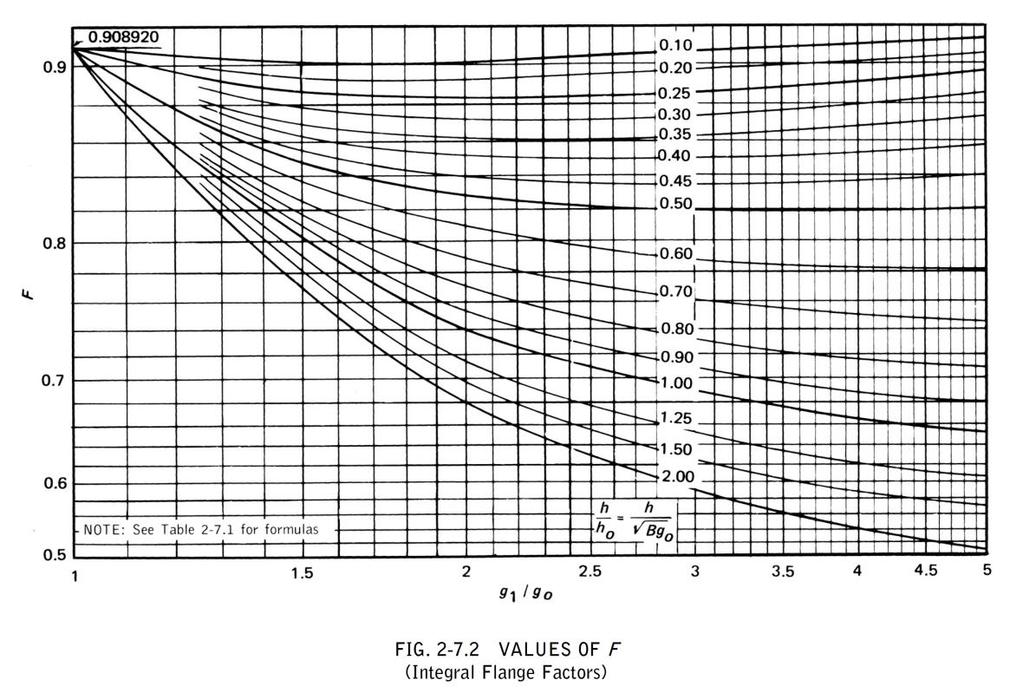
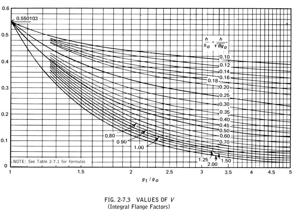
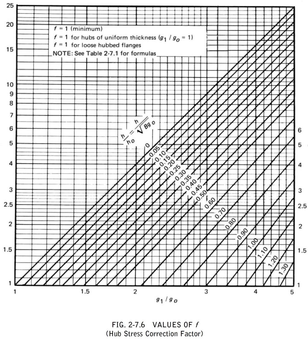
6 Flange Qualification as per ASME Section VIII, Division 1, Appendix 2 Notations The symbols described below are used in the formulas for the design of flanges = outside diameter of flange = cross-sectional area of the bolts using the root diameter of the thread = total required cross-sectional area of bolts taken as greater of and = total cross-sectional area of bolts at root of thread or section of least diameter under stress, required for the operating conditions = total cross-sectional area of bolts at root of thread or section of least diameter under stress = inside diameter of flange = inside diameter of reverse flange = effective gasket or joint-contact-surface seating width = basic gasket seating width (from Table 2-5.2) = bolt-circle diameter = basic dimension used for the minimum sizing of welds = factor = = factor = for integral type flanges = factor = for loose type flanges = factor = for integral type flanges = factor = for loose type flanges = factor for integral type flanges (from Fig ) = factor for loose type flanges (from Fig ) = hub stress correction for integral flanges from Fig (when greater than one, this is the ratio of the stress in the small end of hub to the stress in the large end), (for values below limit of figure, use f = 1.) = diameter at location of gasket load reaction = thickness of hub at small end = thickness of hub at back of flange = total hydrostatic end force = = hydrostatic end force on area inside of flange = = gasket load (difference between flange design bolt load and total hydrostatic end force) = W H = total joint-contact surface compression load = 2b x 3.14 = difference between total hydrostatic end force and the hydrostatic end force on area inside of flange = = hub length
7 = radial distance from the bolt circle, to the circle on which HD acts, as prescribed in Table 2-6 = radial distance from gasket load reaction to the bolt circle = = factor = = distance from the bolt circle, to the circle on which acts, as prescribed in Table 2-6 = ratio of outside diameter of flange to inside diameter of flange = A / B = factor = ( ) = component of moment due to = = component of moment due to = = component of moment due to = = total moment acting upon the flange for the operating conditions or gasket seating as may apply = ( ) for gasket seating condition = for operating condition = width used to determine the basic gasket seating with, based upon the possible contact width of the gasket (see Table 2-5.2) = internal design pressure = radial distance from bolt circle to point of intersection of hub and back of flange. For integral and hub flanges, R = (C-B / 2) g1 = allowable bolt stress at reference temperature = allowable bolt stress at design temperature = allowable stress for material of flange at design temperature (operating condition) = calculated longitudinal stress in hub = calculated radial stress in flange = calculated tangential stress in flange = factor involving K (from Fig ) = flange thickness = factor involving K (from Fig ) = factor for integral type flanges (from Fig ) = factor for loose type flanges (from Fig ) = flange design bolt load, for the operating condition or gasket seating = for operating condition = ( ) for gasket seating condition = minimum required bolt load for the operating conditions = minimum required bolt load for gasket seating = width used to determine the basic gasket seating width, based upon the contact width between the flange and the gasket (see Table 2-5.2) = factor involving K (from Fig ) = gasket or joint-contact-surface unit seating load = factor involving K (from Fig )
8 Calculation of Flange Stresses The stresses in the flange shall be determined for both the operating conditions and gasket seating condition, in accordance with the following formulas: (1) Integral type flanges Longitudinal hub stress = Radial flange stress = ( ) Tangential flange stress = Combined stress and (2) Loose type flanges with hubs Longitudinal hub stress = Radial flange stress = ( ) Tangential flange stress = Combined stress and where, = factor = ( ) = factor = for integral type flanges = factor = = factor for loose type flanges (from Fig ) = factor for loose type flanges (from Fig )
9 (3) Loose type flanges without hubs Longitudinal hub stress = 0 Radial flange stress = 0 Tangential flange stress Combined stress and where, 3 ( te 1) t = factor = T d = factor = U 2 V L h 0 g 0 = factor = F h L o = factor for loose type flanges (from Fig ) = factor for loose type flanges (from Fig ) (4) Optional type flanges (calculated as loose flanges without hubs) Longitudinal hub stress = 0 Radial flange stress = 0 Tangential flange stress Combined stress and where, 3 ( te 1) t = factor = T d = factor = V U L 2 h 0 g 0
10 F = factor = h L o = factor for loose type flanges (from Fig ) = factor for loose type flanges (from Fig ) (5) Reverse type flanges Longitudinal hub stress = Radial flange stress = ( ) Tangential flange stress = Combined stress and where, = factor = ( ) = factor = = factor = = factor = = = = = ( )
11
12
13
14
15
16
17 Problem 1: (Example from Taylor Forge & Pipe Works, 1961 ) Flange Details: Flange Type : Loose Flanges with Hubs Flange Outside Diameter [A] = (inch) Flange Inside Diameter [B] = (inch) Inside Diameter of Reverse Flange [B'] = 20 (inch) Flange Thickness [t] = (inch) Small End Hub Thickness [g0] = (inch) Large End Hub Thickness [g1] = (inch) Hub Length [h] = 2.5 (inch) Allowable Design Temp [sf] = (psi) Allowable Ref. Temp [sfa] = (psi) Design Temp [E] = 2.7E+7 (psi) Ref. Temp [Ea] = 2.92E+7 (psi) Bolting Information: Bolt Circle Diameter = (inch) Number of Bolts = 44 Bolt Diameter = 1 (inch) Allowable Ref. Temp [sa] = (psi) Allowable Design Temp [sb] = (psi) Gasket Information: Gasket Outside Diameter = (inch) Gasket Inner Diameter = (inch) Leak Pressure Ratio [m] = 2.75 Gasket Seating Stress [y] = 3700 (psi) Facing Sketch = 1 Facing Column = 1 Load Data: Design Pressure = 400 (psi) Design Temperature = 500 (F) Axial Force = 1000 (lb) Bending Moment = 200 (ft-lb) Allowable Pressure = 665 (psi)
18 Comparison of Results: Flange Stresses Text Book Results (psi) CAEPIPE (psi) CAESAR II (psi) Operating condition Longitudinal Hub (SH) Radial Flange (SR) Tangential Flange (ST) (SH + SR) (SH + ST) Gasket Seating Condition Longitudinal Hub (SH) Radial Flange (SR) Tangential Flange (ST) (SH + SR) (SH + ST) Problem 2: (Example 10.5 on page 209 Chapter 10 on CASTI Guidebook to ASME Section VIII Div.1 Pressure Vessels Third Edition ) Flange Details: Flange Type : Reverse Flanges Flange Outside Diameter [A] = 49 (inch) Flange Inside Diameter [B] = (inch) Inside Diameter of Reverse Flange [B'] = (inch) Flange Thickness [t] = 5.25 (inch) Small End Hub Thickness [g0] = (inch) Large End Hub Thickness [g1] = (inch) Hub Length [h] = 6 (inch) Allowable Design Temp [sf] = (psi) Allowable Ref. Temp [sfa] = (psi) Design Temp [E] = 2.7E+7 (psi) Ref. Temp [Ea] = 2.92E+7 (psi) Bolting Information: Bolt Circle Diameter = 44 (inch) Number of Bolts = 32 Bolt Diameter = 1.25 (inch) Allowable Ref. Temp [sa] = (psi) Allowable Design Temp [sb] = (psi) Gasket Information: Gasket Outside Diameter = 24 (inch) Gasket Inner Diameter = 22 (inch) Leak Pressure Ratio [m] = 2.50 Gasket Seating Stress [y] = (psi)
19 Facing Sketch = 1 Facing Column = 1 Load Data: Design Pressure = 150 (psi) Design Temperature = 800 (F) Axial Force = 1000 (lb) Bending Moment = 200 (ft-lb) Allowable Pressure = 665 (psi) Comparison of Results: Flange Stresses Text Book Results (psi) CAEPIPE (psi) Operating condition Longitudinal Hub (SH) Radial Flange (SR) Tangential Flange (ST) (SH + SR) (SH + ST) Gasket Seating Condition Longitudinal Hub (SH) Radial Flange (SR) Tangential Flange (ST) (SH + SR) (SH + ST) CAESAR II (psi) Problem 3: (Example from KEDKEP CONSULTING, INC. dated May 27, 2008) Flange Details: Flange Type : Loose Flanges without Hubs / Optional Flanges Flange Outside Diameter [A] = 38.4 (inch) Flange Inside Diameter [B] = 32 (inch) Inside Diameter of Reverse Flange [B'] = 32 (inch) Flange Thickness [t] = 4 (inch) Small End Hub Thickness [g0] = (inch) Large End Hub Thickness [g1] = (inch) Hub Length [h] = (inch) Allowable Design Temp [sf] = (psi) Allowable Ref. Temp [sfa] = (psi) Design Temp [E] = 2.7E+7 (psi) Ref. Temp [Ea] = 2.92E+7 (psi) Bolting Information: Bolt Circle Diameter = 36 (inch) Number of Bolts = 28
20 Bolt Diameter = 1 (inch) Allowable Ref. Temp [sa] = (psi) Allowable Design Temp [sb] = (psi) Gasket Information: Gasket Outside Diameter = (inch) Gasket Inner Diameter = 32 (inch) Leak Pressure Ratio [m] = 0.50 Gasket Seating Stress [y] = 0 (psi) Facing Sketch = 2 Facing Column = 2 Load Data: Design Pressure = 300 (psi) Design Temperature = 295 (F) Axial Force = 1000 (lb) Bending Moment = 200 (ft-lb) Allowable Pressure = 665 (psi) Comparison of Results: Flange Stresses Text Book Results (psi) CAEPIPE (psi) CAESAR II (psi) Operating Condition Longitudinal Hub (SH) Radial Flange (SR) Tangential Flange (ST) (SH + SR) (SH + ST) Bolt Stress Gasket Seating Condition Longitudinal Hub (SH) Radial Flange (SR) Tangential Flange (ST) (SH + SR) (SH + ST) Bolt Stress
WELCOME to CAUx Local India 2018
 WELCOME to CAUx Local India 2018 Flange Design In Detail Prepared by Sachin Pol and Fauzan Badiwale Some Typical Flange Images 3 Some Typical Gasket Images 4 Flange Design As Per ASME Sec.VIII Div.1 Mandatory
Step 1: Step 2: psi psi
 General Tutorial on Evaluation of Nozzles by computing Local Shell Stresses as per WRC 537 and Stress Evaluation as per ASME Section VIII Division 2 using CAEPIPE Whenever Pressure Vessel or Heat exchanger
Subject: FRP Flange Design Ref: Thomas E. Graham, FRP Flanges for Process Pipe and Tanks, NACE, 1989
 Britt Engineering Associates, Inc. Birmingham. Alabama www.beacom.com September 30, 2018 Technical Note Subject: FRP Flange Design Ref: Thomas E. Graham, FRP Flanges for Process Pipe and Tanks, NACE, 1989
Design and Optimization of Weld Neck Flange for Pressure Vessel
 V th International Symposium on Fusion of Science & Technology, New Delhi, India, January 18-22, 2016 ID: 2016-ISFT-430 Design and Optimization of Weld Neck Flange for Pressure Vessel Vinod Kumar 1, Vivek
OPENINGS AND REINFORCEMENTS 26
 ASME BPVC.VIII.1-2015 UG-35.2 UG-36 (4) It is recognized that it is impractical to write requirements to cover the multiplicity of devices used for quick access, or to prevent negligent operation or the
API HPHT 6BX Flange Design, Verification & Capabilities: Example use of Methodology
 API HPHT 6BX Flange Design, Verification & Capabilities: Example use of Methodology January 22 nd, 2018 Summary 1. Determine the suitability of the existing BX gaskets for 20K 2. Use Robert Eichenberg
PVP2006-ICPVT
 Proceedings of PVP2006 / ICPVT-11: 11 th International Conference on Pressure Vessel Technology July 23-37, 2006, Vancouver, Canada PVP2006-ICPVT11-93020 DESIGN OF A LARGE RECTANGULAR FLANGE Bharat Batra,
The Powerful Sealing Calculation
 KLINGER expert 6.0 The Powerful Sealing Calculation The KLINGER expert 6.0 gasket design program is a versatile software to assist users in the selection of non-metallic gasket materials. www.klinger.co.at
A parametric study of metal-to-metal contact flanges with optimised. geometry for safe stress and no-leak conditions
 A parametric study of metal-to-metal contact flanges with optimised geometry for safe stress and no-leak conditions M. Abid *, D. H. Nash a * Faculty of Mechanical Engineering, Ghulam Ishaq Khan Institute
Rules for the Installation, Inspection and Testing of Air Reservoirs (Other than on Locomotives)
") Rules for the Installation, Inspection and Testing of Air Reservoirs (Other than on Locomotives) December 5, 1994 TM Rules for the Installation, Inspection and Testing of Air Reservoirs (Other than on
Rules for the Installation, Inspection and Testing of Air Reservoirs (Other than on Locomotives) December 5, 1994 TM Rules for the Installation, Inspection and Testing of Air Reservoirs (Other than on
CERTIFICATION OF COMPLIANCE OF THE USER S DESIGN SPECIFICATION
 CERTIFICATION OF COMPLIANCE OF THE USER S DESIGN SPECIFICATION I, the undersigned, being experienced and competent in the applicable field of design related to pressure vessel requirements relative to
Quality Plastic Pipe Fittings. Technical Data. Fabricated PVC Fittings IPS Class 100, 125, 160, 200 SCH 40 & SCH 80 Solvent Weld & Gasketed
 Quality Plastic Pipe Fittings Technical Data Fabricated PVC Fittings IPS Class 100, 125, 160, 200 SCH 40 & SCH 80 Solvent Weld & Gasketed Effective April 1, 2002 PIPE DIMENSIONS IPS-IRON PIPE SIZE Minimum
AWWA Pipe Flanges. AWWA C Standard Steel Hub Flanges Class D AWWA C Standard Steel Hub Flanges Class E AWWA C Flange Manufacturer
 WW Pipe Flanges WW Flanges are commonly used in waterworks, wastewater, slurry, plant piping or other light duty applications generally requiring pressures of less than 300 psi. Pressure ratings for WW
Counterbore and Countersink Tutorial
 Counterbore and Countersink Tutorial This tutorial is designed to show how to create a Counterbore hole in two different ways. 1. Creating 2 Extrudes 2. Using the Hole Tool Types of Holes Counterbore Holes
GMS 10.0 Tutorial SEAWAT Viscosity and Pressure Effects Examine the Effects of Pressure on Fluid Density with SEAWAT
 v. 10.0 GMS 10.0 Tutorial SEAWAT Viscosity and Pressure Effects Examine the Effects of Pressure on Fluid Density with SEAWAT Objectives Learn how to simulate the effects of viscosity and how pressure impacts
THE PROCESS OF JOINT INTEGRITY
 BOLTED JOINTS A.333 THE PROCESS OF JOINT INTEGRITY To assist in managing a process, ask yourself the following questions: why, what, who, and how? Why do we need a Flange Joint Integrity program? This
NORDCALC Introduction... 2 Registration... 2 Flow Calculations tab Torque Calculation & Actuator Mounting Data tab... 21
 NORDCALC User Guide Table of Contents NORDCALC Introduction... 2 Registration... 2 Flow Calculations tab... 5 Calculating the gas flow rate for gaseous medium... 6 Calculating the pressure drop for gaseous
Pressures MAOP MOP OP
 MAOP Pressures MAOP MOP OP MAOP "Maximum Allowable Operating Pressure" means the maximum pressure at which a pipeline or segment of a pipeline may be operated under this part. 192.3 MOP "Maximum Actual
Standard Pneumatic Test Procedure Requirements for Piping Systems
 the pressure equipment safety authority Standard Pneumatic Test Procedure Requirements for Piping Systems AB-522 Edition 2, Rev. 1 Issued 2016-10-24 Table of Contents FOREWORD... 1 1.0 INTRODUCTION...
PVP Copyright 2009 by ASME
 Proceedings of PVP 009 009 ASME Pressure Vessel and Piping Division Conference July 6-30, 009, Prague, Czech Republic PVP009-7746 UPDATE OF THE TABULATED «M AND Y» VALUES IN THE NEW REVISIONS OF FRENCH
Combination Analysis Tutorial
 Combination Analysis Tutorial 3-1 Combination Analysis Tutorial It is inherent in the Swedge analysis (when the Block Shape = Wedge), that tetrahedral wedges can only be formed by the intersection of 2
Design and Analysis of Pressure Safety Release Valve by using Finite Element Analysis
 Design and Analysis of Pressure Safety Release Valve by using Finite Element Analysis Mr.V.D.Rathod* 1, Prof.G.A.Kadam* 2, Mr.V. G. Patil* 3 * 1 M.E. Design (Pursuing), SKN Sinhgad Institute of Technology&
Vessels subject to External Pressure
 Basic principles of compressive force Vessels subject to External Pressure Before After The result of just air pressure! Presented by: Ray Delaforce Basic principles of compressive force Consider For a
Tightening Evaluation of New 400A Size Metal Gasket
 Proceedings of the 8th International Conference on Innovation & Management 307 Tightening Evaluation of New 400A Size Metal Gasket Moch. Agus Choiron 1, Shigeyuki Haruyama 2, Ken Kaminishi 3 1 Doctoral
Safety Aspects and Design of the Vent Isolation Chamber. Prepared: W.M. Snow Checked: H. Nann Approved: W. M. Snow
 Safety Aspects and Design of the Vent Isolation Chamber Prepared: W.M. Snow Checked: H. Nann Approved: W. M. Snow 1. Scope This document addresses the safety aspects and design of the vent isolation chamber
APPENDIX B TESTING PROTOCOLS. Method A: Straight Test Method B: Angular Deflection Test. Method C: Shear Load Test
 APPENDIX B TESTING PROTOCOLS Method A: Straight Test Method B: Angular Deflection Test Method C: Shear Load Test B.1 METHOD A. STRAIGHT PIPE JOINT TEST In order to simulate the straight pipe-joint condition
σ = force / surface area force act upon In the image above, the surface area would be (Face height) * (Face width).
 * (Face width).") Aortic Root Inflation Introduction You have already learned about the mechanical properties of materials in the cantilever beam experiment. In that experiment you used bending forces to determine the Young
Aortic Root Inflation Introduction You have already learned about the mechanical properties of materials in the cantilever beam experiment. In that experiment you used bending forces to determine the Young
KISSsoft 03/2016 Tutorial 9
 KISSsoft 03/2016 Tutorial 9 Cylindrical Gear Fine Sizing KISSsoft AG Rosengartenstrasse 4 8608 Bubikon Switzerland Phone: +41 55 254 20 50 Fax: +41 55 254 20 51 info@kisssoft.ag www.kisssoft.ag Table of
Design and Safety Document for the Vacuum Windows of the NPDGamma Liquid Hydrogen Target at SNS
 Design and Safety Document for the Vacuum Windows of the NPDGamma Liquid Hydrogen Target at SNS Prepared: Checked: Approved: H. Nann W. Fox M. Snow The NPDGamma experiment is going to run at BL13 at SNS
B31.3 Piping Checklist and Rules of Thumb March 1, 2008 Program Version Paulin Research Group s
 Paulin Research Group s PRG B31.3 Piping Checklist and Rules of Thumb Program User Guidelines Contents 1.0 Program Objective 2.0 Summary 3.0 Getting Started 4.0 Main Topics Addressed 5.0 Report Discussion
Flange Bolt Torquing. for Resistoflex Plastic-Lined Piping Products. Torquing. Retorquing. Hydrotesting. Annual retorquing
 Flange Bolt Torquing for Resistoflex Plastic-Lined Piping Products Torquing When assembling flange connections, always use a full complement of clean, new high strength A193-B7 bolting. If using stainless
Installation Instructions For Flat Seated Bolted Type RAH Series Disk Holders
 Installation Instructions For Flat Seated Bolted Type RAH Series Disk Holders RA Series Rupture Disks 1. WARNING a) Read the complete instructions before attempting to install the rupture disk and holder
ASME Boiler & Pressure Vessel Code Analysis of the 1497 MHz High-Current Cryomodule Helium Vessel
 1.0 Introduction ASME Boiler & Pressure Vessel Code Analysis of the 1497 MHz High-Current Cryomodule Helium Vessel Katherine Wilson 28 May 2007 To minimize the hazards associated with vacuum and pressure
DUAL GEAR. Button Calculator. Calculates form tools required to make Gear Cutters.
 DUAL GEAR Button Calculator Calculates form tools required to make Gear Cutters. Copyright 2011-2016 D.P.D. Penney Introduction This calculator came into being when I needed to calculate the form tool
Summary of Substantive Changes between the 2004 e1 and 2017 editions of ASSE 1011, Hose Connection Vacuum Breakers
 Summary of Substantive Changes between the 2004 e1 and 2017 editions of ASSE 1011, Hose Connection Vacuum Breakers Presented to the IAPMO Standards Review Committee on October 15, 2018 General: The changes
Precision Duct Systems 4570 Commerce Cir SW Atlanta, GA Phone (404)
") Project Name: Engineer: Contractor: Section Number: Date Submitted: Date Approved: Pressure Class: Material Type: Connections: 2005 Up to 10 wg 1995 2 wg pos 1995 4 wg pos 1995 10 wg 2005 neg WG: 1995
Project Name: Engineer: Contractor: Section Number: Date Submitted: Date Approved: Pressure Class: Material Type: Connections: 2005 Up to 10 wg 1995 2 wg pos 1995 4 wg pos 1995 10 wg 2005 neg WG: 1995
CENTER PIVOT EVALUATION AND DESIGN
 CENTER PIVOT EVALUATION AND DESIGN Dale F. Heermann Agricultural Engineer USDA-ARS 2150 Centre Avenue, Building D, Suite 320 Fort Collins, CO 80526 Voice -970-492-7410 Fax - 970-492-7408 Email - dale.heermann@ars.usda.gov
CONTENTS Article NC-1000 Introduction Figures Article NC-2000 Material
 CONTENTS Foreword... xv Statements of Policy... xvii Personnel... xix Organization of Section III... xxxi Summary of Changes... xxxiii List of Changes in BC Order... xxxiv Article NC-1000 Introduction...
1.2 Example 1: A simple hydraulic system
 Note: It is possible to use more than one fluid in the Hydraulic library. This is important because you can model combined cooling and lubrication systems of a library. The hydraulic library assumes a
COMMITTEE DRAFT. API 520 Part I 10 th Edition Ballot Item 2.1. This ballot covers the following item:
 This ballot covers the following item: API 520 Part I 10 th Edition Ballot Item 2.1 2008 12 Modify guidance to PRV datasheets (Line 17) to assist user s with determining the temperature to use for selecting
ASYBCO 90 O ELBOW LONG RADIUS O.D. I.D.
 90 O ELBOW LONG RADIUS Standard weight Extra strong Schedule 160 Double extra strong ASTM A-234 ASME / ANSI B16.9 Carbon and ferritic alloy steel Produced from X-rayed, stress-relieve welded pipe. Welds
TECHNICAL CIRCULAR. Circular No: S-P 32/13 Revision: 1 Page: 1 of 7 Date:
 Circular No: S-P 32/13 Revision: 1 Page: 1 of 7 Date:22.05.2014 Related Requirement: UR S27 (Rev.6 June 2013) Subject: Retroactive Application for Strength Requirements for Fore Deck Fittings and Equipment
STANDARD SPECIFICATION FOR SPLIT TEES (HOT TAP MATERIAL)
") STANDARD SPECIFICATION FOR SPLIT TEES (HOT TAP MATERIAL) TEE (HOT TAPPING MATERIAL) S-04-02-040 Page 1 of 7 1.0 SCOPE This specification covers the basic requirements for the design, manufacture and supply
STANDARD SPECIFICATION FOR SPLIT TEES (HOT TAP MATERIAL) TEE (HOT TAPPING MATERIAL) S-04-02-040 Page 1 of 7 1.0 SCOPE This specification covers the basic requirements for the design, manufacture and supply
NOTES ON WATER HAMMER. 55
 NOTES ON WATER HAMMER. 55 NOTES ON WATER HAMMER. By A. B. Robison. When the flow conditions of a liquid in a pipe line are varied by the opening or closing of a valve or the equivalent, a change in the
INTRODUCTION TABLE OF CONTENTS
 2 INTRODUCTION Thank you for choosing Servometer to design and manufacture your unique, new electrodeposited bellows for your particular application. The definitions, formulas and design parameters inside
Published by: PIONEER RESEARCH & DEVELOPMENT GROUP (www.prdg.org) 113
 113") Design, Develop And Analysis Of Effortless Pressure Regulator Considering Pressure Vessel Aspect M. B. Chopade 1, S.N. Khan2 1, 2 Mechanical (Design), Pune University Rajarshi Shahu College of Engineering,
Design, Develop And Analysis Of Effortless Pressure Regulator Considering Pressure Vessel Aspect M. B. Chopade 1, S.N. Khan2 1, 2 Mechanical (Design), Pune University Rajarshi Shahu College of Engineering,
Horizontal Bladder Tanks
 DATA SHEET Horizontal Bladder Tanks Features UL Listed and FM Approved for use with various ANSUL proportioners and foam concentrates 175 psi (12.1 bar) maximum allowable working pressure (design pressure)
Pressure Vessel-Tank Sizing
 Pressure Vessel-Tank Sizing Introduction This module is divided into two sections: mechanical design and process design. The mechanical design portion deals mainly with the thickness calculations for vessels
DUPLEX TECHNICAL INFORMATION FABRICATED DUPLEX STRAINERS
 DUPLEX STRAINER TECHNICAL INFORMATION - 119 - SCREEN OPENINGS 100 Mesh - 30% O.A. 0.006 Openings 80 Mesh - 36% O.A. 0.008 Openings 60 Mesh - 38% O.A. 0.010 Openings 40 Mesh - 41% O.A. 0.016 Openings 30
Casing Collapse Pressure for Non-zero Internal Pressure Condition. (Effect of Internal Pressure on Collapse)
") Casing Collapse Pressure for Non-zero Internal Pressure Condition (Effect of Internal Pressure on Collapse) Jiang Wu Chevron ETC August, 2011 API specifies casing collapse rating primarily based on casing
Casing Collapse Pressure for Non-zero Internal Pressure Condition (Effect of Internal Pressure on Collapse) Jiang Wu Chevron ETC August, 2011 API specifies casing collapse rating primarily based on casing
BUTTERFLY VALVES Series 800
 BUTTERFLY VALVES Series 800 WARNING Before proceeding read ALL instructions and become familiar with the equipment and associated drawings. Follow ALL applicable safety regulations and codes for pressurized
SEAWAT Viscosity and Pressure Effects. Objectives Learn how to simulate the effects of viscosity and how pressure impacts the fluid density in SEAWAT.
 v. 10.4 GMS 10.4 Tutorial Examine the Effects of Pressure on Fluid Density with SEAWAT Objectives Learn how to simulate the effects of viscosity and how pressure impacts the fluid density in SEAWAT. Prerequisite
BALL VALVE ASSEMBLY AND MAINTENANCE PROCEDURE. REF. DOC.MMM900N Rev.1 March 2014 SERIES M DIN / ANSI. Page 1 of 17
 SERIES M DIN / ANSI Page 1 of 17 REVIEW CONTROL PROCEDURE REF.DOC.MMM900N REV. DATE CARRIED OUT BY APPROVED BY DESCRIPTION 0 12/05/2013 E.Hidalgo J.Tejedor Initial Edition 1 27/03/2014 D.Grau J.Tejedor
Tutorial 2 Time-Dependent Consolidation. Staging Groundwater Time-dependent consolidation Point query Line query Graph Query
 Tutorial 2 Time-Dependent Consolidation Staging Groundwater Time-dependent consolidation Point query Line query Graph Query Model Set-up For this tutorial we will start with the model from Tutorial 1 Quick
FAQ How to make complete allowable span tables with SandStat?
 FAQ How to make complete allowable span tables with SandStat? SandStat has the ability to calculate complete allowable span tables. This module is not included in the basic version of SandStat and must
Study to Establish Relations for the Relative Strength of API 650 Cone Roof Roof-to-Shell and Shell-to- Bottom Joints
 Thunderhead Engineering Consultants I N C O R P O R A T E D 1006 Poyntz Ave. Manhattan, KS 66502-5459 785-770-8511 www. thunderheadeng.com Study to Establish Relations for the Relative Strength of API
Table NC (e)-1 Stress Range Reduction Factors
-1 Stress Range Reduction Factors") RECORD 15-997 8/2017 PAGE 1 OF 13 (3) If the range of temperature change varies, equivalent full temperature cycles may be computed as follows: Table NC-3611.2(e)-1 Stress Range Reduction Factors Number
RECORD 15-997 8/2017 PAGE 1 OF 13 (3) If the range of temperature change varies, equivalent full temperature cycles may be computed as follows: Table NC-3611.2(e)-1 Stress Range Reduction Factors Number
MSC Guidelines for Pressure Vessels
 References: a. 46 CFR Part 54 Pressure Vessels S. T. Brady, CDR, Chief, Engineering Division b. ASME Boiler and Pressure Vessel Code (BPVC), Section VIII, Division 1, (1998 Edition) c. Navigation and Inspection
Model MTB-ASME Vertical Bladder Tanks
 DATA SHEET Model MTB-ASME Vertical Bladder Tanks Features n UL Listed for use with various proportioners and foam concentrates n 175 psi (12.1 bar) maximum allowable working pressure (design pressure)
Perform Pressure & Leak Test, Tubing & Piping. Module 12306
 Perform Pressure & Leak Test, Tubing & Piping Module 12306 Instrumentation Trainee Task Module 12306 PERFORM PRESSURE AND LEAK TEST, TUBING AND PIPING Objectives Upon completion of this module, the trainee
Model MTB-ASME Horizontal Bladder Tanks
 DATA SHEET Model MTB-ASME Horizontal Bladder Tanks Features n UL Listed and FM Approved for use with various proportioners and foam concentrates n 175 psi (12.1 bar) maximum allowable working pressure
MONOPLACE HYPERBARIC CHAMBER FOR DIVERS TRANSPORT MODEL OXICAB MO-BZ-TR TECHNICAL OFFER
 TECHNICAL OFFER MONOPLACE HYPERBARIC CHAMBER FOR DIVERS TRANSPORT Supplied by HYPERBARIC S.A.C. LIMA - PERÚ hyperbaric@hyperbaricsac.com ***The images and illustration included are in some cases for reference.
1 Exam Prep. Tabs and Highlights
 1 Exam Prep NFPA 14: Standard for the Installation of Standpipe and Hose Systems Tabs and s These 1 Exam Prep tabs are based on the NFPA 14: Standard for the Installation of Standpipe and Hose Systems,
Optimize Nozzle Location For Minimization Of Strees In Pressure Vessel
 IJIRST International Journal for Innovative Research in Science & Technology Vol. 1, Issue 1, June 2014 ISSN(online): 2349-6010 Optimize Nozzle Location For Minimization Of Strees In Pressure Vessel Shyam
Model MTB-ASME Vertical Bladder Tanks
 DATA SHEET Model MTB-ASME Vertical Bladder Tanks Features n UL Listed for use with various proportioners and foam concentrates n 175 psi (12.1 bar) maximum allowable working pressure (design pressure)
Tank Tie off Report for Pipes Albuquerque 1/3
 Tank Tie off Report for Pipes Albuquerque 1/3 Summary: The following report contains an analysis created by Core Engineering LLC for NuStar Energy. This report was commissioned to analyze anchor points
VISIMIX TURBULENT. MECHANICAL CALCULATIONS OF A CONSOLE SHAFT
 VISIMIX TURBULENT. MECHANICAL CALCULATIONS OF A CONSOLE SHAFT This example shows how to perform mechanical calculations required to check the shaft reliability, including mechanical strength and vibration
SHIMADZU LC-10/20 PUMP
 SHIMADZU LC-10/20 PUMP Clarity Control Module ENG Code/Rev.: M091/70C Date: 24.10.2017 Phone: +420 251 013 400 DataApex Ltd. Fax: +420 251 013 401 Petrzilkova 2583/13 clarity@dataapex.com 158 00 Prague
Wafer Check Valve. Contents. User s Manual. (1) Be sure to read the following description of our product warranty 1
 Be sure to read the following description of our product warranty 1") Serial No. H-V066-E-3 Wafer Check Valve User s Manual Contents (1) Be sure to read the following description of our product warranty 1 (2) General operating instructions 2 (3) General instructions for
Serial No. H-V066-E-3 Wafer Check Valve User s Manual Contents (1) Be sure to read the following description of our product warranty 1 (2) General operating instructions 2 (3) General instructions for
Sprocket Selection Guidelines
 Sprocket Selection Guidelines Table 1 Information Necessary to Order Sprockets 1. Chain Size Number, type, or drawing number of the chain to be used on the sprocket. (The suitability of a sprocket depends
American Society of Sanitary Engineering PRODUCT (SEAL) LISTING PROGRAM
 LISTING PROGRAM") American Society of Sanitary Engineering PRODUCT (SEAL) LISTING PROGRAM ASSE STANDARD #1019 - REVISED: 2011 Wall Hydrant with Backflow Protection and Freeze Resistance MANUFACTURER: CONTACT PERSON: E-MAIL:
American Society of Sanitary Engineering PRODUCT (SEAL) LISTING PROGRAM ASSE STANDARD #1019 - REVISED: 2011 Wall Hydrant with Backflow Protection and Freeze Resistance MANUFACTURER: CONTACT PERSON: E-MAIL:
CLASS D - SENSITIVE LEAK TEST GAS AND BUBBLE METHOD. 1.1 To provide definitive requirements for PNEUMATIC pressure testing of piping systems.
 Page 1 of 7 CLASS D - SENSITIVE LEAK TEST GAS AND BUBBLE METHOD 1. SCOPE 1.1 To provide definitive requirements for PNEUMATIC pressure testing of piping systems. 1.2 The piping system as used herein is
PIP PNE00012 Piping Examination and Leak Test Guide
 October 2017 Piping PIP PNE00012 Piping Examination and Leak Test Guide PURPOSE AND USE OF PROCESS INDUSTRY PRACTICES In an effort to minimize the cost of process industry facilities, this Practice has
February 5, 2014 REQUEST FOR ADDITIONAL INFORMATION FOR THE REVIEW OF THE MODEL NO PACKAGE
 February 5, 2014 Mr. Patrick W. McGuire, Assistant Manager Nuclear Material Stabilization Project Savannah River Operations Office U.S. Department of Energy P.O. Box A Aiken, SC 29802 SUBJECT: REQUEST
Tension Cracks. Topics Covered. Tension crack boundaries Tension crack depth Query slice data Thrust line Sensitivity analysis.
 Tension Cracks 16-1 Tension Cracks In slope stability analyses with cohesive soils, tension forces may be observed in the upper part of the slope. In general, soils cannot support tension so the results
Serving. Petrochemicals Power Semiconductor Waste Treatment Oil & Gas Transmission Lines Bulk Gas Plants
 Serving Petrochemicals Power Semiconductor Waste Treatment Oil & Gas Transmission Lines ulk Gas Plants Mining & Metals Pharmaceuticals Pulp & Paper Mills Sugar Mills Nuclear Desalinization Plants NOTES:
Vertical Bladder Tanks
 DATA SHEET Vertical Bladder Tanks Features UL Listed and FM Approved for use with various ANSUL proportioners and foam concentrates 175 psi (12.1 bar) maximum allowable working pressure (design pressure)
WHEATLEY WHEATLEY SERIES 500 SWING CHECK VALVE. Installation, Operation and Maintenance Manual
 WHEATLEY SERIES 500 SWING CHECK VALVE STANDARD INTEGRAL SEAT & OPTIONAL REMOVABLE SEAT 2" FP - 6" FP 150# - 1500# 8" FP - 12" FP 150# - 900# API 6D and B16.34 2" FP - 4" FP 5000# DRILLING PRODUCTION VALVE
VISIMIX TURBULENT. LIQUID - SOLID MIXING. DEFINING JSS (JUST SUSPENSION SPEED)
") VISIMIX TURBULENT. LIQUID - SOLID MIXING. DEFINING JSS (JUST SUSPENSION SPEED) One of the most important requirements to liquid - solid mixing processes is prevention of sedimentation of solid particles
VISIMIX TURBULENT. LIQUID - SOLID MIXING. DEFINING JSS (JUST SUSPENSION SPEED) One of the most important requirements to liquid - solid mixing processes is prevention of sedimentation of solid particles
Serving. Petrochemicals Power Semiconductor Waste Treatment Oil & Gas Transmission Lines Bulk Gas Plants
 Serving Petrochemicals Power Semiconductor Waste Treatment Oil & Gas Transmission Lines ulk Gas Plants Mining & Metals Pharmaceuticals Pulp & Paper Mills Sugar Mills Nuclear Desalinization Plants NOTES:
East Building, PHH-30 U.S. Department New Jersey Avenue S.E. of Transportation Washington, D.C DOT-SP (ELEVENTH REVISION)
") East Building, PHH-30 U.S. Department 1200 New Jersey Avenue S.E. of Transportation Washington, D.C. 20590 Pipeline and Hazardous Materials Safety Administration DOT-SP 11808 (ELEVENTH REVISION) EXPIRATION
East Building, PHH-30 U.S. Department 1200 New Jersey Avenue S.E. of Transportation Washington, D.C. 20590 Pipeline and Hazardous Materials Safety Administration DOT-SP 11808 (ELEVENTH REVISION) EXPIRATION
DESIGN AND ANALYSIS OF PRESSURE VESSEL
 DESIGN AND ANALYSIS OF PRESSURE VESSEL Vrushali Dilip Solapurkar 1 Assistant Professor, Mechanical Engineering Department, Vadodara Institute of Engineering, Gujarat, India ABSTRACT This technical paper
Design of Pressure vessel for the Hydrocarbon release from the Vent Header Lines
 Design of Pressure vessel for the Hydrocarbon release from the Vent Header Lines Bhargav Mangesh Joshi 1 1Student, Department of mechanical engineering, Modern college of engineering, Pune-5 ---------------------------------------------------------------------***---------------------------------------------------------------------
ENGINEERING DESIGN GUIDE. D-M-E Hydraulic Unscrewing Device
 ENGINEERING DESIGN GUIDE D-M-E Hydraulic Unscrewing Device ENGINEERING DESIGN GUIDE D-M-E Hydraulic Unscrewing Device Hydraulic Unscrewing Device Without guiding thread with cam Safety Considerations Mold
Guidelines for Pressure Boundary Bolted Flange Joint Assembly
 ASME PCC-1 2010 (Revision of ASME PCC-1 2000) Guidelines for Pressure Boundary Bolted Flange Joint Assembly A N A M E R I C A N N A T I O N A L S T A N D A R D ASME PCC-1 2010 (Revision of ASME PCC-1 2000)
OST1. Effects on Fatigue Life of Gate Valves Due to Higher Torque Switch Settings During Operability Testing. and
 r-ppsvf r, INEL-95/0557 JAN 1 6 1335 December 1995 OST1 Effects on Fatigue Life of Gate Valves Due to Higher Torque Switch Settings During Operability Testing W. D. Richins S. D. Snow G. K. Miller M.J.
USA (Bartlett, IL) Division
 Division") USA (Bartlett, IL) Division USA (Bartlett, IL) Division 100+ years Manufacturing Experience Six Sigma Black Belt (2) 350,000 Sq. Ft. Manufacturing & Office Total Program Development & Management Product
USA (Bartlett, IL) Division USA (Bartlett, IL) Division 100+ years Manufacturing Experience Six Sigma Black Belt (2) 350,000 Sq. Ft. Manufacturing & Office Total Program Development & Management Product
MSC Guidelines for Independent Fuel Tanks
 References: Contact Information a. 46 CFR 58.50 (Independent Fuel Tanks) b. 46 CFR 119.440 (Independent Fuel Tanks) c. 46 CFR 182.440 (Independent Fuel Tanks) C. J. Robuck, LCDR, Chief, Engineering Division
Analysis and Optimization of Stress on Horizontal Pressure Vessel by Varying Opening Angle and Location
 Analysis and Optimization of Stress on Horizontal Pressure Vessel by Varying Opening Angle and Location Bhupendra V. Barjod #1, Prof. Ronak Shah *2 # PG student Mechanical Department, Kalol Institute of
Design and Static Structural Analysis of Cylinder and Piston of Two Stage Reciprocating Compressors Using ANSYS
 Design and Static Structural Analysis of Cylinder and Piston of Two Stage Reciprocating Compressors Using ANSYS Manjunatha.T.R 1, Dr. Byre Gowda.H.V 2, Prabhunandan.G.S 3 P.G. Student, Department of Mechanical
V5197A. Firing Rate Gas Valve APPLICATION FEATURES PRODUCT HANDBOOK
 V5197A Firing Rate Gas Valve PRODUCT HANDBOOK APPLICATION The V5197A are firing rate valves used to provide variable flow control of air, natural gas, liquefied petroleum (LP), and manufactured gases.
BALL VALVE ASSEMBLY AND MAINTENANCE PROCEDURE FOR LCV BALL VALVES REF. DOC. MMM LCVE Rev.0 July 2010 SERIES SFF & SFR.
 SERIES SFF & SFR SFF / SFR EN/ANSI/ASME/API/BS/NF SFF EN/DIN/BS/NF Page 1 of 16 REVIEW CONTROL PROCEDURE REF.: DOC. MMM LCVE REV. DATE CARRIED OUT BY APPROVED BY DESCRIPTION 0 19/07/2010 J. Rubio J.Tejedor
NOTICE REGARDING CODE CASES OF THE ASME B31 CODE FOR PRESSURE PIPING
 NOTICE REGARDING CODE CASES OF THE ASME B31 CODE FOR PRESSURE PIPING All B31 Code Cases in effect as of September 1, 007 will remain available for use unless annulled by the B31 Standards Committee. B31
Design and optimization of a low pressure vessel
 Abstract Research Journal of Engineering Sciences ISSN 2278 9472 Design and optimization of a low pressure vessel Available online at: www.isca.in, www.isca.me Received 8 th April 2017, revised 11 th July
PTF4 Pivotrol Pump (patented) version Dual Mechanism - Pressure Powered Pump
 version Dual Mechanism - Pressure Powered Pump") Local regulations may restrict the use of this product to below the conditions quoted. In the interests of development and improvement of the product, we reserve the right to change the specification without
Local regulations may restrict the use of this product to below the conditions quoted. In the interests of development and improvement of the product, we reserve the right to change the specification without
Multi-chambered volume synchroniser Type MZB
 HYDRAULIC Multi-chambered volume synchroniser Type MZB Date of issue: 2001-07-03 Table of contents Description of the multi-chambered volume-synchroniser General points...................................................3
VK/VP SERIES : Sealless Vertical Pump. Assembling Instructions 2010
 VK/VP SERIES : Sealless Vertical Pump Assembling Instructions 2010 20610 Manhattan Place Suite 116 Torrance, CA 90501 Phone: 310-328-9114 Fax: 310-328-9441 1. Motor Shaft and Pump Base (1) (2) Place a
Module # 8 DISTILLATION AND ABSORPTION COLUMN
 Module # 8 MECHANICAL DESIGN OF MASS TRANSFER COLUMN: DESIGN OF DISTILLATION AND ABSORPTION COLUMN 1. Design and construction features of column internals 1.1. Plate construction 1.2. Downcomer details
MJA Rev 10/17/2011 1:53:00 PM
 Problem 8-2 (as stated in RSM Simplified) Leonard Lye, Professor of Engineering and Applied Science at Memorial University of Newfoundland contributed the following case study. It is based on the DOE Golfer,
SCREEN OPENINGS FOR STRAINERS
 SCREEN OPENINGS FOR STRAINERS 100 Mesh - 30% O.A. 0.006 Openings 80 Mesh - 36% O.A. 0.008 Openings 60 Mesh - 38% O.A. 0.010 Openings 40 Mesh - 41% O.A. 0.016 Openings 30 Mesh - 45% O.A. 0.022 Openings