Soma Wind Generators
|
|
|
- Donna Warren
- 5 years ago
- Views:
Transcription
 SAA Wind Loading Manufactured by SOMA WIND GENERATORS 8/62 Lords Place, ORANGE NSW 2800 AUSTRALIA all us M: 0414 986 830 or M: 0407 669 313 EMAIL info@somawindgenerators.com.")
1 Soma Wind Generators 13M WINH TOWER INSTALLATION MANUAL ERTIFIED to AS4100 Steel Structures ode AS3995 (1994) Design of Steel Lattice Towers and Masts AS (1989) SAA Wind Loading Manufactured by SOMA WIND GENERATORS 8/62 Lords Place, ORANGE NSW 2800 AUSTRALIA all us M: or M: somawindgenerators.com.au
2 1. OMPONENT HEKLIST The 13 metre tower kit from Sunrise Solar contains the following parts: DESRIPTION QTY HEKED 15m of wire rope with one end crimped on thimble m of wire rope with one end crimped on thimble m of flex wire rope with one end crimped on thimble 1... Turnbuckles 9... Brake Winch 1... Small D Shackles Large D Shackle for end of winch rope 1... Wire rope grips Thimbles mm dia x 120mm stainless steel bolt & nut mm dia x 120mm stainless steel bolt & nut mm dia x 25mm galvanised bolt & nut mm dia x 90mm galvanised bolt & nut mm dia x 120mm galvanised bolt & nut 1... Top guy sleeve 1... Middle guy sleeve 1... Base plate for poles mm dia steel wire loops 4... Winch bracket 1... Steel plate with six holes 1... Installation manual 1... Sunrise Solar have completed a checklist at the time of packing to minimise the chance of short supply. However, check that all parts are present before going to site if possible. TOWER POLES The poles are supplied seperately from the tower kit. If you have ordered poles as well, you should have recieved two 80mm NB (nominal bore or inside diameter) 6.5m lengths of galvanised pipe. These are for the centre mast. Also you should have recieved one 65mm NB 6.5m length of galvanised pipe for the gin pole. This is used for leverage to raise the centre mast. The three lengths of pipe will all be pre drilled and ready for installation. A general idea of the location of these components is given in fig 1. YOU SUPPLY :STEEL ROPE GREASE, LOTITE 262, ONRETE AND REINFORING FOR THE ONRETE. For reinforcing you will need 48x600mm lengths of 12mm reinforcing bar (12 in each outside hole) and 10x900mm lengths of 12mm reinforcing bar for the centre hole. If you need to put foundations into rock then contact Sunrise Solar for advice on using chemical rock anchors. When ordering concrete you will need at least 1.7m 3. You may need a little extra depending on how neat you dig the holes. Also, if the soil is very sandy you may need larger holes. The Loctite 262 is required for some of the bolts both on the tower and the wind generator. The grease is used to protect the ropes and fittings from corrosion, especially in coastal areas. The recommended grease is Rocol Wire Rope Lubricant, or equivalent. It should be applied at installation and annually thereafter.
3 2. FOUNDATIONS 2.1 Layout The concrete foundations for the tower should be laid at least 2 days prior to installing the tower. Holes for the foundations should be dug in accordance with fig. 2. The centre hole should be 1m x 1m x 0.25m deep. The 4 outside holes should each be 0.7m x 0.7m x 0.7m for a SOMA1000 wind generator. If the soil is sandy, then go larger on the holes. In laying out the foundations you must decide in which direction you wish to lower the mast then layout the holes accordingly. Holes no. 2 & 4 should be slightly forward and below the centre hole if possible. This will ensure that the guys slacken as soon as the tower begins to lower. If holes 2 & 4 were to be a bit to the winch side of centre or a good deal higher than the centre hole then it is possible that the guys attached to these holes may tension and resist the the tower from being lowered. This would not be catastrophic, but would necessitate the slackening of the turnbuckles on these wires before lowering the tower, which is inconvenient. Holes 1, 3 & 5 should be in line with each other, but their relationship in the vertical direction is not terribly important, i.e. they don't have to lie in the same horizontal plane. All guy ropes have a couple of metres of extra length to allow for uneven ground situations. 2.2 oncreting Once the holes are dug you should place the steel wire loops, winch bracket, base plate and reinforcing rod near their respective holes. Place some flexible or corrugated conduit in the centre hole so that after the concrete has set, you have a means of neatly bringing your cable up from it's trench into the inside of the mast. Pour the concrete and place the reinforcement rod in during pouring. Immediately after pouring a hole, while the concrete is still wet, push in the steel loop or bracket for that hole. The steel loops should be angled towards the top of the pole. The base plate should sit flush on top of the centre pad and the vertical fins should be in line with holes 1 & 3. The upper 22mm hole in the baseplate fins should be closest to the winch. The winch bracket should be angled slightly backwards away from the tower with the channel side facing away from the tower. Leave 400mm of winch bracket protruding above the concrete. Allow the concrete 2 days to set before connecting the poles to the base plate and raising the tower. After a few hours though, once the concrete has gone off, you can proceed to layout the poles in position and connect the guy wires to the outside steel loops if you wish. 3 ASSEMBLY AND RAISING THE TOWER 1. Take the 80mmNB pipe with the 22mm hole in one end and lay it out on the ground in the direction that it will lower to, with the hole at the centre bracket. 2. Use a 20mm dia. Stainless steel bolt to bolt it to the lower hole in the centre plate. 3. Feed the connecting cable up the conduit that you placed in the centre concrete pad and through this first length of pipe, pulling through an extra 7m of cable beyond the end of the pipe. 4. Feed the centre sleeve down over the cable onto the top of this pipe.
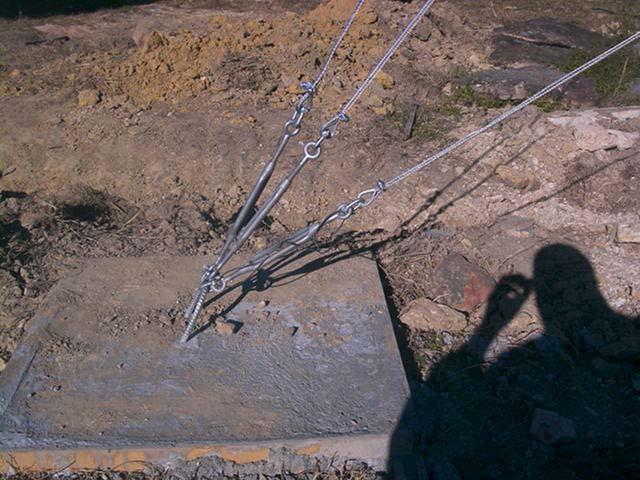
4 5. Feed the excess cable through the second length of 80mm pipe with the two 12mm holes in this pipe being at the top of the mast. 6. Slide the centre sleeve over the first pipe and tighten the two bolts, making sure that the fins on the sleeve are in line with the outside foundations. 7. Slide the top sleeve down over the top of the mast until it lines up with the lower 18mm holes in the mast, about 1.5m from the top. Bolt the sleeve on using the high tensile bolt provided and Loctite on the nut. Use the spare 10mm dia x 120mm bolt and nut to bolt into the hole near the top of the mast. This can be used to anchor the electrical cable so that the wind generator connections are not bearing the weight of the cable inside the mast. 8. Rotate the top pole until the fins on the top sleeve line up with the outside foundations, then push the pipe into the centre sleeve and tighten the bolts. 9. Lay the 65mm gin pole on top of the first 80mm pipe and bolt it to the upper hole in the base plate using the remaining 20mm stainless bolt. 10. Bolt the steel plate inside the free end of the gin pole. 11. Shackle the crimped end of the 15m upper guy wires to the top sleeve. 12. Shackle the crimped end of the 11m lower guy wires to the centre sleeve. 13. Measure off the top guys at 13m and feed each of them around a thimble using one rope grip to secure temporarily. Repeat for the centre guys at 9m length. 14. Shackle each thimble to a turnbuckle and adjust each turnbuckle to the midway point. 15. Shackle the other end of each turnbuckle to the appropriate steel loop on the outside foundations. The ropes that connect to the ginpole attach to the one shackle in one of the holes in the steel plate attached to the end of the gin pole. 16 onnect the flexible 14m winch cable to the winch drum and using the large D shackle, connect the crimped end to the other hole in the steel plate at the end of the gin pole. Also feed the remaining turnbuckle onto this same shackle. This turnbuckle will be used for connecting the gin pole to the steel loop in the concrete next to the winch. Ensure this turnbuckle is in the midway position. While the tower is still on the ground, apply grease to all of the wire ropes, rope grips, thimbles and turnbuckles. This should be done annually to reduce corrosion. 17. Bolt the winch to the winch bracket then grease all ropes and fittings. 18. Winch the tower into the upright position checking that the guy ropes are not getting too tight on the way up. If any are, then loosen by releasing some rope through the rope grip. Shackle the turnbuckle on the end of the gin pole to the steel loop next to the winch bracket. 19. heck that the tower is straight and vertical and release each rope grip one at a time, taking up any slack in the ropes. 20. Attach the remaining rope grips making sure there are three on each guy, attaching the loose ends neatly up the guys. See fig Adjust the turnbuckles to put tension on each guy. 22. To lower the tower, unscrew the turnbuckle attaching the gin pole to the winch foundation. Wind the winch handle backwards to lower, checking that the guy wires are getting looser. Raise and lower the tower a couple of times until you are happy that it is ready for the wind generator. 23. Lower the tower and allow the top of the mast to sit at comfortable working height above the ground, then attach the wind generator as per the manufacturer's instructions. 24. Raise the wind generator once wiring is completed to the battery. 25. Using fencing wire or something of similar strength, lock the turnbuckles in place so they cannot vibrate loose. Do this by passing a length of wire through one eye of the turnbuckle, through the body of the turnbuckle and then through the other eye, twisting the two loose ends together.
5 Shackle Top Sleeve Tower lowers away from winch entre Sleeve 3 Rope Grips Thimble Shackle Turnbuckle Brake Winch Base Plate Gin Pole Winch Bracket Steel Loop Sunrise Solar 13m Winch Tower Fig 1
6 Tower lowers in this direction 3 6.5m mm 6.5m 6.5m 6.5m 1 oncrete Pad 150mm Guy Loop Winch Bracket Fig 2. Plan view of 13m Tower Foundations not to scale
7 Fig 3 Guy Wire Reinforcing Hinge Bracket m Fig 4. Raising the Tower


8 WINH FOOTING ENTRE BASEPLATE GUY WIRE FOOTING
9 13 METRE TOWER - PIPE DRILLING DETAIL (dim. in mm) 35 LOWER MAST mm NB GAL PIPE MEDIUM WALL 6.5M UPPER MAST 65mm NB med. wall gal pipe protruding 40mm into 80mm mast and welded to mast. Dia. 12mm hole is drilled through 80mm and 65mm pipes mm NB GAL PIPE MEDIUM WALL 6.5M GIN POLE mm NB GAL PIPE MEDIUM WALL 6.5M 22 NOTE: ALL HOLES THROUGH BOTH SIDES OF PIPE Fig 5.
Installation and Training Manual
 AirForce1 Tower Kit Installation and Training Manual FuturEnergy Limited Ettington Park Business Centre Stratford upon Avon CV37 8BT +44 (0)1789 451070 Table of Contents Safety Notes... 3 Parts Supplied
TOWER INSTALLATION MANUAL For A.R.E. Guyed Pipe Towers Short Towers 43, 64 and 85 feet tall
 TOWER INSTALLATION MANUAL For A.R.E. Guyed Pipe Towers Short Towers 43, 64 and 85 feet tall Contents 1) Introduction...2 2) Site Selection and Preparation...2 3) Tools List...3 4) Parts List...4 5) Tower
Tripod Setup Guide (M-TPx)
") Items needed: 1/2 inch wrench, mast level (M-MLA), medium size wire cutters, crescent wrench, all-purpose grease, tape measure, tie wraps, redi-mix cement (optional), shovel (optional), sledge hammer (for
Items needed: 1/2 inch wrench, mast level (M-MLA), medium size wire cutters, crescent wrench, all-purpose grease, tape measure, tie wraps, redi-mix cement (optional), shovel (optional), sledge hammer (for
IS37 10 Metre Instrument Mast Handbook
 IS37 10 Metre Instrument Mast Handbook Version 10.1 6 th February 2014 Environdata Australia Pty Ltd 42-44 Percy Street Warwick Queensland 4370 Australia Phone: (07) 4661 4699 Fax: (07) 4661 2485 International
QUALITY ALUMINUM BOAT LIFTS, INC. INSTRUCTIONS. Dominator Lake Lift
 INSTRUCTIONS Dominator Lake Lift PHONE:251-986-3882 * FAX:251-986-3136 QABLDOMINATORINST.2014 P a g e 1 Quality Aluminum Boat Lifts, INC. Installation Instructions: Dominator Lake Lift Thank you for your
WHISPER 42 FOOT (13 Meter) TOWER KIT for SKYSTREAM 3.7 AND WHISPER 500 WIND TURBINE
 TOWER KIT for SKYSTREAM 3.7 AND WHISPER 500 WIND TURBINE") WHISPER 42 FOOT (13 Meter) TOWER KIT for SKYSTREAM 3.7 AND WHISPER 500 WIND TURBINE Made in the USA by: SOUTHWEST WINDPOWER, INC. 1801 Route 66 Flagstaff, AZ 86001 (928) 779-9463 SOUTHWEST WINDPOWER Page
WHISPER 42 FOOT (13 Meter) TOWER KIT for SKYSTREAM 3.7 AND WHISPER 500 WIND TURBINE Made in the USA by: SOUTHWEST WINDPOWER, INC. 1801 Route 66 Flagstaff, AZ 86001 (928) 779-9463 SOUTHWEST WINDPOWER Page
Low Wind High Yields Series
 Low Wind High Yields Series Wind Turbines USER S MANUAL Introduction Low Wind High Yields Series rotor blades apply the latest advanced thermoplastic engineering and are manufactured by precision injection
45-FOOT LAND TOWER KIT For AIR TM WIND MODULES
 45-FOOT LAND TOWER KIT For AIR TM WIND MODULES Made in the USA by: Primus Wind Power 938 Quail Street Lakewood, CO 80215 USA (303) 242-5820 AIR is a trademark of Primus Wind Power Inc. Page 1 of 26 45-Foot
27 FOOT LAND TOWER KIT For AIRtm WIND MODULE
 27 FOOT LAND TOWER KIT For AIRtm WIND MODULE Made in the USA by: Southwest Windpower 1801 W. Route 66 Flagstaff, AZ 86001 (928) 779-9463 AIR is a trademark of Southwest Windpower Inc. 27 Foot LAND TOWER
THOR 10 HAMMER CAGE INSTRUCTIONS
 75 " 7m 78 4" m 6" 8.8m 45 ".70m 4.9deg 6 4" 6m 44 4".67m 75 " 7m 9 4" 0m 44".m 497 4".64m The 70, Thor Hammer Cage, consists of four heavy duty aluminum net poles. The unique pole structure reduces the
Model: 5100 OmniSteel Volleyball System
 Model: 5100 OmniSteel Volleyball System Installation, Operation and Maintenance Instructions Please read all instructions before attempting installation or operation of these units SAVE THESE INSTRUCTIONS
TRI-POD SETUP. Guidelines for Typical Field Setup. Site Selection
 TRI-POD SETUP Guidelines for Typical Field Setup Site Selection Use the following guidelines to help you choose an appropriate site for setting up the Station and protecting against field hazards. When
Model: 7200 Collegiate Volleyball System
 Model: 7200 Collegiate Volleyball System Installation, Operation and Maintenance Instructions Please read all instructions before attempting installation or operation of these units SAVE THESE INSTRUCTIONS
Installation Instructions MODEL VSTI-A020 Tank Indicator Installation Model: VSTI-A020, Stainless Reverse Read System Versa Steel Inc. Guide Cables No
 Tank Indicator Installation Model: VSTI-A020, Stainless Reverse Read System Guide Cables No Guide Cables 1 August 4, 2011 Assembly Instructions: (Shown with a 2 board, 12 ft kit) ITEM NO. PART NUMBER DESCRIPTION
Guyed 70 Foot Tower Kit for Skystream 3.7 Owner s Manual
 Guyed 70 Foot Tower Kit for Skystream 3.7 Owner s Manual 3-CMLT-1028-03 REV F Installation Operation 2013 XZERES Corp All Rights Reserved Please read this manual thoroughly before beginning assembly. If
How to install AEA s 10 meter meteorological tower
 How to install AEA s 10 meter meteorological tower Before you start: This guide assumes that you have obtained permission from the land owner, consulted with US Fish & Wildlife Service and obtained approval
BALL STOP INSTALLTION GUIDE
 BALL STOP INSTALLTION GUIDE GROUND SLEEVE INSTALLATION: 1. Locate the exact location of the ground sleeve. NOTE: Maximum recommended pole spacing is 20 feet on center. 2. Excavate the pole footing; refer
Installation Instructions
 116-3027, 116-3017 X-Pando Adjustable Steel Protector Installation Instructions 1404 N. Marshall Ave. El Cajon CA. 92020 For technical support call us at (800) 368-3075 NB 6/28/10 607-0112 Step 1. Mounting
3/8" Safety Cable Systems
 3/8" Safety Cable Systems Ladder-Mount 3/8" Cable System (No Slider) Kits include appropriate length of aircraft cable, top and bottom support brackets, 12" tensioning turnbuckle, tension spring, and all
20', 15', AND 12' BALL STOPS ASSEMBLY INSTRUCTIONS
 20'-0" 15'-0" 1 739020 739020A 20' BALL STOP; STRAIGHT POLE 739015 739015A 15' BALL STOP; STRAIGHT POLE 739012 739012A 12' BALL STOP; STRAIGHT POLE Read all of the instructions before beginning. Make sure
REPLACING THE AFT RUDDER CABLES
 REPLACING THE AFT RUDDER CABLES Note: You must have the assistance of a qualified Aircraft Mechanic to perform this procedure. A logbook entry with the mechanics signature is required. Please read these
First Team Sports, Inc. Blast Recreational Volleyball System
 First Team Sports, Inc. Blast Recreational Volleyball System BILL OF MATERIALS A 2 Volleyball Vertical Post K 1 ½ Centerlock Nut B 3 Net Clamp L 2 Carabiner Clip C 1 Pulley Clamp M 1 ½ x 2 Hex Bolt D 4
Hoisting Equipment Cable puller & Accessories
 Yale hoists and trolleys are not ed for Cable puller model Yaletrac Pulling force 800-3200 It has a light weight, compact, high tensile aluminium alloy housing with a large flat bottom surface for increased
BRAKE WINCH RUP 503-[T/BT] EQUIPMENT FOR LIFTING LOADS. AT 053-[T/BT] xx
![BRAKE WINCH RUP 503-[T/BT] EQUIPMENT FOR LIFTING LOADS. AT 053-[T/BT] xx](/thumbs/88/115945274.jpg "BRAKE WINCH RUP 503-[T/BT] EQUIPMENT FOR LIFTING LOADS. AT 053-[T/BT] xx") Reference number: BRAKE WINCH RUP 503-[T/BT] EQUIPMENT FOR LIFTING LOADS DESIGNATED USE The brake winch RUP 503-[...]T series is a load lifting / lowering device. Device is equipped with safety brake for
Reference number: BRAKE WINCH RUP 503-[T/BT] EQUIPMENT FOR LIFTING LOADS DESIGNATED USE The brake winch RUP 503-[...]T series is a load lifting / lowering device. Device is equipped with safety brake for
Security and confidence at height.
 A Security and confidence at height. Vertical Systems DISTRIBUTED BY M DBI-SALA Vertical Systems are designed to complement your ability to work while meeting all applicable OSHA and ANSI standards. Vertical
PULLTARP INSTALLATION & OPERATORS MANUAL
 PULLTARP INSTALLATION & OPERATORS MANUAL Step 1. Mounting Positions Determine the mounting position for your truck Fig. 1 - Fig. 7. Fig. 1 Fig. 2 Fig. 3 A Mount Top Or Bottom Roll B Mount Top Or Bottom
TOWER INSPECTION REPORT
 3010 S. Hwy 77, Suite 600 Waxahachie, Texas 75165 http://ctctower.com Office: 972/923-9504 Fax: 972/923-9619 TOWER INSPECTION REPORT PREPARED FOR MR. CUSTOMER 1,563 GUYED TOWER NEAR CITY, STATE JANUARY
HOBO Station Tri-pod Setup Guide
 HOBO Station Tri-pod Setup Guide Part #: MAN-TRIPOD Doc #: D-12317-A Contact Information For support, please contact the company that you bought the product from: Onset Computer Corporation or an Onset
INSTALLATION MANUAL Version 7 FOR CONNECTION TO FRONIUS IG15, SMA WB1700 & SMA WB1100 GRID CONNECT INVERTERS WITHOUT BATTERIES.
 INSTALLATION MANUAL Version 7 FOR CONNECTION TO FRONIUS IG15, SMA WB1700 & SMA WB1100 GRID CONNECT INVERTERS WITHOUT BATTERIES. Manufactured by SOMA POWER PTY LTD 18/13 Gibbens Road West Gosford NSW 2250
NEXT GENERATION FLEX FENCE
 NEXT GENERATION FLEX FENCE Area To Be Fenced.. With Next Generation Flex Fence any post that is not in a straight line with another post must be braced. Layout your fence installation. Determine all end
Parts List. 7. Handlebars 8. Grips 9. Handlebar Stem 10. Front Brake 11. Front Wheel 12. Crank 13. Chain
 Woodworm Cruise Parts List 1. Free Wheel with Rear Hub 2. Fenders 3. Fender Stay 4. Quick Release 5. Saddle 6. Seat Post 7. Handlebars 8. Grips 9. Handlebar Stem 10. Front Brake 11. Front Wheel 12. Crank
65 FOOT LAND TOWER KIT For WHISPER 100 AND 200 WIND TURBINES
 65 FOOT LAND TOWER KIT For WHISPER 100 AND 200 WIND TURBINES Made in the USA by: Southwest Windpower 1801 West Route 66 Flagstaff, AZ 86001 (928) 779-9463 Whisper is a trademark of Southwest Windpower
ASSEMBLY MANUAL HOBIE CATSY
 ASSEMBLY MANUAL HOBIE CATSY HOBIE CAT EUROPE ZI Toulon Est, BP 50 8078 Toulon cedex 9, France Tel : + (0)9 08 78 78 - Fax : + (0)9 08 99 Email : hobiecat@hobie-cat.net - http://www.hobie-cat.net ASSEMBLY
Premium PowerPoint Presentation. Rigging Review
 Premium PowerPoint Presentation Rigging Review Chapter 1 Hoisting Safety Review: What about the CG Symmetrical vs. Asymmetrical Balanced and Unbalanced Lifting Lug Hooks Angle Deformation Safety Gates
Stand-N-Fish FULL DETAIL INSTALLATION INSTRUCTIONS
 1 Stand-N-Fish FULL DETAIL INSTALLATION INSTRUCTIONS Thank you for purchasing the incredible new Stand-N-Fish Kayak Fishing System. Once installed on your kayak the Stand-N-Fish will take your kayak fishing
80 SERIES MOBILE-KARRIERS. The Specialist In Drum Handling Equipment OPERATOR S MANUAL FOR MORSE 80 SERIES
 OPERATOR S MANUAL FOR MORSE Model 80A and 80A-M for 55 gallon standard steel drums (22½ diameter) Model 80C for steel or fiber drums (21-23 diameter) Model 80i for 55 gallon steel drum (22-½ diameter).
Installation, Operating, Inspection and Maintenance Instructions Ladder Climber s Safety System. Warning
 OWNER'S MANUAL Installation, Operating, Inspection and Maintenance Instructions Ladder Climber s Safety System Model # s: 6000, 6001, 6010 Warning You must read and fully understand all instructions, or
HOME ASSEMBLY INSTRUCTIONS
 HOME ASSEMBLY INSTRUCTIONS This Papillionaire Bicycle now belongs to you. It will take you to work, wait patiently outside your local cafe, and carry your groceries home. This is the start of your long-term
IMPORTANT: If you have questions on the use, care, or suitability of this equipment for your application, contact DBI/SALA.
 User Instruction Manual Precast Concrete Beam Horizontal Lifeline System This manual is provided as the Manufacturer s Instructions, and should be used as part of an employee training program as required
Installation and Service Manual
 Pika Econo-Tower Guyed Tower Kit Installation and Service Manual Pika Energy 2015 Installation Instructions for the Pika EconoTower Revision Table Revision Date Changes 1.0 2014-04-08 Initial Release
Page 1 of 1 04/19/13 SBR
 Office of Roadway Engineering - Plan Insert Sheets Number Title Date Number Title Date Number Title Date 201015 Extension of Anchor Bolts 07/20/12 207000 Bikeway Pavement Marking Details 01/18/13 202010
STATIONARY TRUCK INTERNAL HALYARD V-CLEAT FLAGPOLES FOR QUICK AND PROFESSIONAL INSTALLATION READ ALL INSTRUCTIONS BEFORE PROCEEDING
 9390 South 300 West, Sandy, Utah 84070 801-562-0123 800-782-0500 ColonialFlag.com STATIONARY TRUCK INTERNAL HALYARD V-CLEAT FLAGPOLES FOR QUICK AND PROFESSIONAL INSTALLATION READ ALL INSTRUCTIONS BEFORE
E-trike Li Assembly Guide
 PREPARATION 1. Read this assembly manual BEFORE commencing assembly. 2. Carefully remove all the components and packaged hardware from the shipping boxes. 3. Unpack the contents of the large double box
No ' Long No ' Long
 ASSEMBLY, INSTALLATION & USAGE MANUAL BATTING CAGES No. 0150-50' Long No. 0170-70' Long No. 0150 BATTING CAGE - 50' Long No. 0170 BATTING CAGE - 70' Long Upon completion of the assembly/installation of
Cable Replacement Instructions for R-Series Roust-A-Bout 100/150/250
 Cable Replacement Instructions for R-Series Roust-A-Bout 100/150/250 US 7514 Alabonson Road Houston, TX 77088 phone: 281-999-6900 fax: 281-999-6966 Canada 1721 Bishop St. Unit #4 Cambridge, ON N1T 1N5
FNFB-30 (30 FT FIELDPRO FOOTBALL BACKSTOP SYSTEM) Installation Instructions
 Installation Instructions") FNFB-30 (30 FT FIELDPRO FOOTBALL BACKSTOP SYSTEM) Installation Instructions Call Jaypro Sports Equipment at 1-800-243-0533 during regular business hours for technical support. www.jaypro.com Rev: - Page
FNFB-30 (30 FT FIELDPRO FOOTBALL BACKSTOP SYSTEM) Installation Instructions Call Jaypro Sports Equipment at 1-800-243-0533 during regular business hours for technical support. www.jaypro.com Rev: - Page
Troyer s Gourd Rack 8 unit F R H O P
 B E A D I M-N L Vertical Parts F R H O P Horizontal Parts C G J Updated 11/16 Parts List A: Top of Pole B: Bottom of Pole C: 48 Ground Stake D: Top Perch rods 48 long E: Hub F: Rope Winder w/ attached
Bowsprit Hinge on "Bumble Chugger" By Robin Whittle, Shrimper 124 (Bumble Chugger) (Winter 2003)
 (Winter 2003)") Bowsprit Hinge on "Bumble Chugger" By Robin Whittle, Shrimper 124 (Bumble Chugger) (Winter 2003) In April 2003 Practical Boat Owner (PBO) published an article which I had written on the use of the bowsprit
Bowsprit Hinge on "Bumble Chugger" By Robin Whittle, Shrimper 124 (Bumble Chugger) (Winter 2003) In April 2003 Practical Boat Owner (PBO) published an article which I had written on the use of the bowsprit
Certified in 3 & 4 leg configurations to CEN/TS 16415:2013 for maximum 2 persons and EN 795:2012 for single person use. total edge management system
 Certified in 3 & 4 leg configurations to CEN/TS 16415:2013 for maximum 2 persons and EN 795:2012 for single person use total edge management system the world s most versatile modular total edge management
2,500/4,000 LB Easy Riser Vertical Cable Feighner Lift
 2,500/4,000 LB Easy Riser Vertical Cable Feighner Lift CAUTION - PUT SAFETY FIRST 1. Before attempting to install or operate this lift, study and fully understand the proper operating procedures and safety
Shade Sail DIY. Installation Guide
 DIY Shade Sail Installation Guide DISCLAIMER: All information provided here is a general guide only. Installation of shade sails can vary depending on may factors including but not limited to, fixing points,
Drive Belt Instructions
 Drive Belt Safety Do not roll, pry, twist, invert or bend the belt back on itself. Do not zip tie the belt. The acceptable temperature range for your belt drive is -53 C to 85 C. Do not lubricate the belt
M32 CATAMARAN ASSEMBLY MANUAL
 M32 CATAMARAN ASSEMBLY MANUAL 1 M32 CATAMARAN ASSEMBLY MANUAL MANUAL SUMMARY M32 ASSEMBLY Parts and tools Instructions MAST PLATFORM Parts and tools Instructions MAST STEPPING Instructions MAIN HALYARD
SPOOLER INSTRUCTIONS. STEP 12 If you are going to paint your posts, that should be done at this time.
 STEP 4 Starting where you marked the end post location, move down your fence line 6 feet and make another mark. This mark is where your second upright post will be installed. Continuing down the fence
STRAIGHT POLE TENSIONED BATTING TUNNEL POLE LAYOUT
 STRAIGHT POLE TENSIONED BATTING TUNNEL POLE LAYOUT SOFTBALL: 55' x 14' Nets BASEBALL: 75' x 14' Nets No. 330155 No. 330175 63'-0" 83'-0" SINGLE NET 1 1 No. 330255 No. 330275 63'-0" 83'-0" DOUBLE NET No.
1.0 - OPENING AND CLOSING THE DOOR
 The purpose of this manual is to provide the user with instructions on how to safely open and close, how to conduct routine maintenance, and how to install the PEI TWINLOCK Closure on a pressure vessel.
BANKSMAN / SLINGER. 1. What is the smallest size diameter of synthetic rope allowed for use as a hand held tagline?
 BANKSMAN / SLINGER 1. What is the smallest size diameter of synthetic rope allowed for use as a hand held tagline? A. 16mm B. 10mm C. 12mm 2. What is the maximum temperature that a webbing sling can be
Assembly Guide ST200 FUNCTIONAL TRAINER
 Assembly Guide ST200 FUNCTIONAL TRAINER Assembly Guide ST200 FUNCTIONAL TRAINER To avoid possible damage to this Functional Trainer, please follow these assembly steps in the correct order. Before proceeding,
Methods of installation of ADSS fiber optic cables
 Methods of installation of ADSS fiber optic cables Two main methods recommended by the cable manufacturers: A. Mobile Cable Reel method generally recommended for span < 50 m B. Static Cable Reel method
Telescopic winch handle Speedfriend"
 Winch handles, jib furlers JIB FURLERS - WINCH HANDLES - SPREADER COVERS 57 Floating winch handles Floating universal size winch handles Fitted with "Lock In" winch system; universal size for any winch;
RESCUE LIFTING DEVICE RUP 503-[...] AT 053-[...] xx
![RESCUE LIFTING DEVICE RUP 503-[...] AT 053-[...] xx](/thumbs/90/102827869.jpg "RESCUE LIFTING DEVICE RUP 503-[...] AT 053-[...] xx") EN 1496:2006 / B Reference number: RESCUE LIFTING DEVICE RUP 503-[...] AT 053-[...] xx DESIGNATED USE The rescue lifting device RUP 503-[...] series is a component of rescue system. Using this device the
EN 1496:2006 / B Reference number: RESCUE LIFTING DEVICE RUP 503-[...] AT 053-[...] xx DESIGNATED USE The rescue lifting device RUP 503-[...] series is a component of rescue system. Using this device the
coolaroo.com Protection all year round Installing your new Coolaroo all weather sail is simple, following our step-by-step instructions.
 Protection all year round Installing your new Coolaroo all weather sail is simple, following our step-by-step instructions. Features Provides 100% UV block Water resistant M ade with UV stabilised knitted
OPERATIONS/PARTS MANUAL FOR PATTERSON'S MODEL # WWP40M-LPS-6 LOW-PROFILE BARGE CONNECTOR WINCH
 W. W. Patterson Company 3 Riversea Road Pittsburgh, PA 15233 Phone: 800-322-2018 FAX: 412-322-2785 OPERATIONS/PARTS MANUAL FOR PATTERSON'S MODEL # WWP40M-LPS-6 LOW-PROFILE BARGE CONNECTOR WINCH Please
Bladerider X8 Assembly Help Notes
 2.1 Remove All Parts & Have Some Tools Handy Remove all items from the box and identify each part as per the packing sheet and check that nothing is missing. If there is something missing, please email
Anchors that can be used for a lifeline in a grain bin. or Ladder do not make good anchors!
 Anchors that can be used for a lifeline in a grain bin. or Ladder do not make good anchors! Definitions: Carabiner 1 Webbing attachment hardware with double locking action rated at 4,000 pounds 8 mm Accessory
Zip-Line Kit Instructions
 1 Zip-Lines Ireland - Zip-Line Kit Instructions DC001A Zip-Line Kit Instructions Thank you for your purchase of the ZLI Zip-line kit! This product was engineered to provide safe fun for all ages when the
Serial Number: Lot Number: Purchase Date: General Factors Accepted / Rejected Supportive Details or Comments. Accepted Rejected.
 Full Body Harness Harness Model: General Factors / Supportive Details or Comments 1.) Hardware: (includes D-rings, buckles, keepers, and back pads) Inspect for damage, distortion, sharp edges, burrs, cracks
Installation Manual. BWC XL.1 Tilt.Tower. 18 m (59 ft) Tilt.Tower 24 m (78 ft) Tilt.Tower 29 m (97 ft) Tilt.Tower. Version 4 May 2006
 Tilt.Tower 24 m (78 ft) Tilt.Tower 29 m (97 ft) Tilt.Tower. Version 4 May 2006") Version 4 May 2006 BWC XL.1 Tilt.Tower Installation Manual 18 m (59 ft) Tilt.Tower 24 m (78 ft) Tilt.Tower 29 m (97 ft) Tilt.Tower Bergey Windpower Co., Inc. 2200 Industrial Blvd. Norman, OK 73069 USA
Version 4 May 2006 BWC XL.1 Tilt.Tower Installation Manual 18 m (59 ft) Tilt.Tower 24 m (78 ft) Tilt.Tower 29 m (97 ft) Tilt.Tower Bergey Windpower Co., Inc. 2200 Industrial Blvd. Norman, OK 73069 USA
GATE INSTALLATION INSTRUCTIONS
 For Technical Support: 1-877-862-7049 GATE INSTALLATION INSTRUCTIONS What You Need: Posthole digger 4 long, 2 diameter galvanized pipe For Loose Soil 3 additional 3 long, 2 diameter galvanized pipe Level,
2012-June-12 SECOND DRAFT Hobie Getaway Spinnaker Installation Instructions
 SECTION A: INTRODUCTION This unofficial set of installation instructions was written for a 2009 Hobie Getaway, using a 2012 Hobie Spinnaker Kit 20999020. Note from the Author: I had never seen this kit
OUTDOOR BACKSTOP WITH 5'-0" EXTENSION
 INSTALLATION INSTRUCTIONS OUTDOOR BACKSTOP WITH 5'-0" EXTENSION NoUU. 00175- _ READ ALL INSTRUCTIONS THOROUGHLY BEFORE ATTEMPTING TO INSTALL THIS EQUIPMENT. INSTALLATION / ASSEMBLY OF THIS EQUIPMENT MUST
Symptom: The basic symptom is your sail will not roll in or out without force. The drum unit is hard to turn. Your sail will not roll out on its own.
 Schaefer 2100 roller furler drum replacement on Catalina 320 Danny Jensen, A BOA VIDA hull #972, Thanks to contributions Chris Burti, Jeff Hare and C320 group for comments Photos were taken and edited
Standard Hangers and Adapters
 Standard s and Adapters Cable Gripping Tabs Prevent cable slippage without the need for a permanently installed hoisting grip. Pre-Assembled and Captivated Hardware Eliminates the need for field assembly.
TRAVSMART permanent single-cable horizontal lifeline system
 The Travsmart single-line system provides a smooth travel. It allows the traveler to move freely over the intermediate anchors, minimizing wear and eliminating user assistance. The user s hands remain
Rudder Kit Assembly Instructions for Quest 13
 Rudder Kit Assembly Instructions for Quest 13 Revised 4/2/2015 78501 Rudder System The Hobie Quest is designed for the addition of an optional rudder system. Rudder systems in boats like this allow you
Installation Instructions - Electric Aluminum Drive Systems for Arm Sets to 22 Electric Arm Systems , ,
 Installation Instructions - Electric Aluminum Drive Systems for Arm Sets to 22 Electric Arm Systems - 204-025, 206-025, 22-025 NB /0/ 607-0020 404 N. Marshall Ave. El Cajon CA. 92020 For technical support
Installation Instructions - Electric Steel Drive Systems for Arm Sets to ,
 Installation Instructions - Electric Steel Drive Systems for Arm Sets to 22 208-025, 209-025 NB /0/ 607-0029 404 N. Marshall Ave. El Cajon CA. 92020 For technical support call us at (800) 368-3075 Step.
Ref Part Part # Qty Letter A Rudder Catcher B X 1/2 PH Bolts C Rudder Bracket
 Ref Part Part # Qty A Rudder Catcher 07.2694.0000 1 J B Q A B 10-32 X 1/2 PH Bolts 07.2136.0000 10 C Rudder Bracket 07.2689.0000 1 D Kayak Pad Eye 01.1315.0430 2 E Cherry Rivets 01.1315.0459 4 H T N P
Ropes for Subsea Cable Laying
 Ropes for Subsea Cable Laying SEAMASTER CABLE LAID BUOY & GRAPNEL ROPES [ BUOY & GRAPNEL ] Cable Laid combined (wire and natural fibre) ropes specially designed for Subsea Cable Laying duties Designed
SERIES 2 RAMP OWNER S MANUAL TOOLS REQUIRED: BEFORE YOU BEGIN... Read and understand these instructions before beginning a ramp setup.
 SERIES 2 RAMP OWNER S MANUAL BEFORE YOU BEGIN... Read and understand these instructions before beginning a ramp setup. Use caution and care for your back when lifting, pushing, pulling, folding or unfolding
Flagpole Selection Guide
 Selection Guide Selecting the right pole for your project To chose the right pole you should consider both flagpole Style and Height. The common styles are outlined on this page for easy comparison. The
S.R.A. Fully Engineered Product Range
 Safety Roof Anchors S.R.A. Fully Engineered Product Range Issue 01.2017 www.safetyroofanchors.com.au S.R.A. Fully Engineered Product Range 400 Series Truss-T-Grip Profile Grip SRA Static Line Ladder Restraint
PUNE TECHTROL PVT LTD. Instruction and Maintenance Manual for Float and Tape Gauge FTG
 PUNE TECHTROL PVT LTD Instruction and Maintenance Manual for and Tape Gauge FTG INSTALLATION, OPERATION AND MAINTENANCE MANUAL FOR FLOAT AND TAPE GAUGE FTG 1 Introduction : It is used to measure and indicate
FIRST TEAM SPORTS, INC Storm Portable Series Assembly Instructions
 FIRST TEAM SPORTS, INC Storm Portable Series Assembly Instructions WARNING! WARNING! WARNING! THIS BASKETBALL SYSTEM IS SPRING LOADED AND SHIPPED UNDER TENSION. ATTEMPTING TO ASSEMBLE OR DISASSEMBLE ANY
DM-MBST (English) Dealer's Manual. ROAD MTB Trekking. City Touring/ Comfort Bike. Shifting lever. EZ-FIRE Plus ST-EF500 ST-EF510
 Dealer's Manual. ROAD MTB Trekking. City Touring/ Comfort Bike. Shifting lever. EZ-FIRE Plus ST-EF500 ST-EF510") (English) DM-MBST001-00 Dealer's Manual ROAD MTB Trekking City Touring/ Comfort Bike URBAN SPORT E-BIKE Shifting lever EZ-FIRE Plus ST-EF500 ST-EF510 CONTENTS IMPORTANT NOTICE... 3 TO ENSURE SAFETY...
(English) DM-MBST001-00 Dealer's Manual ROAD MTB Trekking City Touring/ Comfort Bike URBAN SPORT E-BIKE Shifting lever EZ-FIRE Plus ST-EF500 ST-EF510 CONTENTS IMPORTANT NOTICE... 3 TO ENSURE SAFETY...
Backboard and Rim Owners Manual
 REQUIRED TOOLS AND MATERIALS: Two (2) Capable Adults Tape Measure Backboard and Rim Owners Manual Customer Service Center N53 W24700 South Corporate Circle Sussex, WI 53089 U.S.A. Step Ladder - 8ft. (2.4
Installation and Operating Instructions for Automotive Winch Synthetic Rope
 Installation and Operating Instructions for Automotive Winch Synthetic Rope 2 1 Synthetic Rope Kit Parts List Part No. 251262 1. Rope Assembly (3/8 x 100 ) 2. Hook Strap WARNING: A minimum of EIGHT wraps
Figure 1 - Parts Identification
 Instructions for the following series products: Zorbit Energy Absorber Kits (See back page for specific model numbers.) User Instruction Manual Zorbit Energy Absorber Kits for Horizontal Lifeline Systems
USER MANUAL. Beach volleyball posts BEACH CHAMP ID:
 USER MANUAL Beach volleyball posts BEACH CHAMP ID: 111203 INDEX USER MANUAL FOR BEACH VOLLEYBALL POSTS BEACH CHAMP General information Overview Overview: Floor mounting options City Beach - for a freestanding
Bike Rack and Tire Carrier
 Bike Rack and Tire Carrier OWNER'S MANUAL Rev: 10.26.2017 Page 1 Bike Rack and Tire Carrier Owners Manual TABLE OF CONTENTS System 2 Description 2 Prior To Operation 3 Manual Slide-Out Bike Rack Operation
First Team Sports, Inc. Stellar Recreational Volleyball System
 First Team Sports, Inc. Stellar Recreational Volleyball System BILL OF MATERIALS A 2 Volleyball Vertical Post K 1 ½ Centerlock Nut B 2 Height Labels L 2 Carabiner Clip C 3 Net Clamp M 1 ½ x 2 Hex Bolt
AMTEC SUPPORT GRIPS STANDARD, HEAVY DUTY & CONDUIT GRIPS
 AMTEC SUPPORT GRIPS STANDARD, HEAVY DUTY & CONDUIT GRIPS DESIGNED TO HOLD THE WEIGHT FOR ELECTRICAL CABLE AS IT HANGS IN VERTICAL, SLOPING OR HORIZONTAL POSITIONS. EASILY INSTALLED AND REMOVED USING NO
PRO1030 Bi-Directional Assembly Replacement
 PRO1030 Bi-Directional Assembly Replacement 1. Remove both side covers using the Crank and Cover Removal procedure. Fig. 1 2. Disconnect both brake cables (not shown) from the brake (S3611). (Fig. 1) 3.
Mainz Product Catalogue
 2019 Mainz Product Catalogue Stainless steel wire, fittings, hardware and tools for wire balustrades Stainless steel wire Stainless steel hardware and fittings Tools Mainz Pty Ltd Ph: (08) 92756246 www.wirebalustrades.com.au
SHEET 2: VERTICAL INSTALLATION
 IMAGE OW1291 OW1293 OW1295 OW1297 AVATAR OW1301 OW1303 OW1305 OW1307 OW1311 OW1313 OW1315 OW1317 OW1331 OW1333 OW1335 OW1337 SHEET 2: VERTICAL INSTALLATION SHEET 3: HORIZONTAL INSTALLATION Drawing: 760883XX
For ANCHOR WINCH Model: T Big Water 45 T sw Salt Water Series Big Water 45
 INSTALLATION AND OPERATING INSTRUCTIONS ANCHOR WINCHES For ANCHOR WINCH Model: T10110-45 Big Water 45 T10103-45sw Salt Water Series Big Water 45 If you have any questions or difficulty installing this
Array Solutions 350 Gloria Rd Sunnyvale, TX Phone FAX
 Array Solutions 350 Gloria Rd Sunnyvale, TX 75182 Phone 972-203 2008 FAX 972-203 8811 E-mail: info@arraysolutions.com Installation Instructions AS-AYL-4 WM Array Solutions K9AY Loop Wire/Mast Kit Thank
Intro: by firechim on October 3, 2013
 by firechim on October 3, 2013 Intro: Step 1: Guide for installing chimney liners with a tee connection This guide is to give you step by step instructions to install a chimney liner that utilizes a tee
BEAMGUARD SAFETY POST TM INSTRUCTIONS
 BEAMGUARD SAFETY POST TM INSTRUCTIONS READ THESE WARNINGS BEFORE USING THE BEAMGUARD SAFETY POST! 1. Before use of this system, read and understand all instructions, warnings, cautions and notes marked
Schaefer recognized this issue and they offer to replace the drum bearing assembly for $
 Schaefer 2100 roller furler drum replacement on Catalina 320 Danny Jensen, A BOA VIDA hull #972, Thanks to contributions Chris Burti, Jeff Hare and C320 group for comments Photos were taken and edited