NIMBUS 4 NIMBUS PROFESSIONAL
|
|
|
- Irma Cummings
- 5 years ago
- Views:
Transcription


1 NIMBUS 4 NIMBUS PROFESSIONAL INSTRUCTIONS FOR USE with people in mind
2
3 Contents General Safety iii Introduction About this Manual Intended use About Nimbus 4 and Nimbus Professional Nimbus Pump Nimbus 4 Mattress Mattress CPR and Transport Controls Nimbus Professional Mattress Clinical Applications Indications Contraindications Cautions Care of the patient when sitting Installation Preparing the System for Use Installing the Mattress Installing the Pump Testing the Power Fail Alarm Connecting the Tubeset Disconnecting the Tubeset System Operation Controls, Alarms and Indicators Pump Controls Pump Indicators Operation Installing the System Inflating the Mattress Comfort Control Operating Modes Shut Down Mattress Vent Valves Guidelines for Selecting Mattress Vent Valves to Open Transport Control Deflating the Mattress CPR Control Nimbus Professional Mattress: Patient Positioning Guide General Supine Position (face up) Prone Position (face down) - Not for Homecare Environment Decontamination (i)
4 Routine Maintenance Nimbus 4 and Nimbus Professional Systems Nimbus Pump Nimbus 4 and Nimbus Professional Mattresses Serial Number Labels Troubleshooting Technical Specification (ii)
5 GENERAL SAFETY Before you connect the system pump to a mains socket, read carefully all the installation instructions contained within this manual. The system has been designed to comply with regulatory safety standards including: EN :1990/A13:1996 and IEC :1988/A2:1995. UL , UL and CAN/CSA C22.2 No M90. EN :2006, EN :2010 and IEC :2005. AAMI/ANSI ES :2006 and CAN/CSA C22.2 No (2008). Safety Warnings It is the responsibility of the care giver to ensure that the user can use this product safely. Whilst the patient is unattended, the decision to use safety sides should be based on clinical assessment and in line with local policy. Alignment of the bed frame, safety sides and the mattress should leave no gap wide enough to entrap a patient's head or body, or to allow egress to occur in a hazardous manner where entanglement with the mains power cable and tubeset or air hoses may result. Care should be exercised to prevent occurrence of gaps by compression or movement of the mattress. Death or serious injury may occur. Make sure that the mains power cable and tubeset or air hoses are positioned to avoid causing a trip or other hazard, and are clear of moving bed mechanisms or other possible entrapment areas. The mains power cable of this pump is designed to allow movement of the bed, and should be fitted into the cable management flaps along the sides of the mattress, as described in this manual. Electrical equipment may be hazardous if misused. There are no user-serviceable parts inside the pump. The pump's case must only be removed by authorised technical personnel. No modification of this equipment is allowed. The mains power socket/plug must be accessible at all times. To disconnect the pump completely from the electricity supply, remove the plug from the mains power socket. The CPR control and/or the CPR indicator tag must be visible and accessible at all times. Disconnect the pump from the mains power socket before cleaning and inspecting. Keep the pump away from sources of liquids and do not immerse in water. Do not use the pump in the presence of uncontained flammable liquids or gasses. The cover of this product is vapour permeable but not air permeable and may present a suffocation risk. Do not use the mattress without a cover, it provides a protective barrier. Bags supplied with this equipment may present a suffocation risk; to avoid the risk of suffocation keep the bags away from babies and small children. When not fitted to a bed, the bed hooks on the pump may present a hazard to small children. Store the pump in a safe place. Only the pump and mattress or seat combination as indicated by ArjoHuntleigh should be used. The correct function of the product cannot be guaranteed if incorrect pump and mattress or seat combinations are used. (iii)
6 Precautions For your own safety and the safety of the equipment, always take the following precautions: Placing extra layers between the patient and the mattress potentially reduces the benefits provided by the mattress and should be avoided or kept to a minimum. As part of sensible pressure area care, it is advisable to avoid wearing clothing which may cause areas of localised high pressure due to creases, seams, etc. Creases in the top cover and placing objects in pockets should be avoided for the same reason. Do not expose the system, especially the mattress, to naked flames, such as cigarettes, etc. In the event of a fire, a leak in the seat or mattress could propagate the fire. Do not use or store the system in direct sunlight. Do not use phenol-based solutions to clean the system. Make sure the system is clean and dry prior to use or storage. Never use sharp objects or electrically heated under blankets on or under the system. Store the pump and mattress in the protective bags supplied. Pets and children must be supervised in the vicinity of the system. Electromagnetic Compatibility (EMC) This product complies with the requirements of applicable EMC Standards. Medical electrical equipment needs special precautions regarding EMC and needs to be installed in accordance with the following instructions: The use of accessories not specified by the manufacturer may result in increased emissions by, or decreased immunity of, the equipment, affecting its performance. Portable and mobile radio frequency (RF) communications equipment (e.g. mobile/cell phones) can affect medical electrical equipment. If this equipment needs to be used adjacent to other electrical equipment, normal operation must be checked before use. For detailed EMC information contact ArjoHuntleigh service personnel. Environmental Protection Incorrect disposal of this equipment and its component parts, particularly batteries or other electrical components, may produce substances that are hazardous to the environment. To minimise these hazards, contact ArjoHuntleigh for information on correct disposal. Expected Service Life The Nimbus pump has an expected service life of seven years. To maintain the condition of the pump, have the pump serviced regularly according to the schedule recommended by ArjoHuntleigh. Do NOT use unapproved accessories or attempt to modify, disassemble or otherwise misuse the Nimbus 4 and Nimbus Professional system. Failure to observe this caution could result in injury, or in extreme cases, death. Design Policy and Copyright and are trademarks belonging to the ArjoHuntleigh group of companies. As our policy is one of continuous improvement, we reserve the right to modify designs without prior notice. The content of this publication may not be copied either whole or in part without the consent of ArjoHuntleigh. ArjoHuntleigh 2013 (iv)
7 1. Introduction About this Manual Intended use About Nimbus 4 and Nimbus Professional This manual is your introduction to the Nimbus 4 and Nimbus Professional systems. You must read and fully understand this manual before using the system. Use this manual to initially set up the system, and keep it as a reference for day-to-day routines and as a guide to maintenance. If you have any difficulties in setting-up or using the Nimbus 4 and Nimbus Professional systems, contact your local ArjoHuntleigh sales office, listed at the end of this manual. The intended use of this product is to prevent and/or manage pressure ulcers for patients up to 250 kg (550 lb). The Nimbus 4 and Nimbus Professional systems should be used as part of a prescribed plan of care (refer to Indications on page 5). Nimbus 4 and Nimbus Professional are highly effective Dynamic Flotation Systems providing active therapy for the prevention, treatment and management of pressure ulcers. The systems consist of a pump and mattress replacement which can be used on top of standard hospital and normal domestic beds. Beds with divided sections for independent elevation of a patient's head and/or knees can be adjusted with these mattresses in position. Both systems use the same Nimbus pump, which has two operating modes: Dynamic mode that cycles the support surface beneath the patient every 10 minutes providing periods of pressure relief for the whole body. Static mode where the support surface remains constant (all cells equally inflated). The Nimbus Professional mattress combines all the qualities of the Nimbus range of mattresses with the added benefit of optional head cell deflate; this will assist the clinician with a range of nursing procedures including prone nursing, intubation, neck cannulation and hygiene, while the body of the mattress continues to provide optimal alternating pressure redistribution. Both mattresses have been designed with specialised Vent Valves, so that some of the cells (including the three head cells on the Nimbus Professional mattress) 1
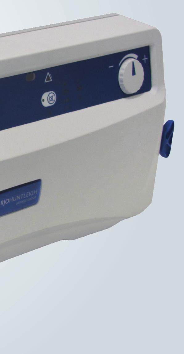
8 Nimbus Pump Run/Standby Button can be selectively deflated to assist with pressure area care and patient management. The mattresses incorporate an advanced AutoMatt sensor pad which ensures the patient is automatically supported at optimum pressures regardless of size, height, position or weight distribution. Both mattresses incorporate the five Heelguard cells at the foot end of the mattress which ensure that the patient s heels are provided with the maximum pressure relief. If cardiac arrest occurs, the mattresses can be rapidly deflated using the CPR (Cardio-Pulmonary Resuscitation) control to allow cardiac resuscitation procedures to be performed. A full technical description of the Nimbus 4 and Nimbus Professional system can be found in the Service Manual, part No. SER0007, available from ArjoHuntleigh. Carry Handle (recess) Alarm Indicators Comfort Control Mains Power Cable Tubeset Connector Front Panel Static Control Mute Control 2
9 Nimbus 4 Mattress 5 Heelguard Cells 3 Head Section Cells (Constant Pressure) 8 Torso Cells 4 Thigh Cells CPR/Transport Control FOOT END HEAD END 5 Vent Valves Carry Handle Drag Handle Securing Strap Detachable Cover Cable Management Flap CLOSED OPEN Mattress CPR and Transport Controls CPR Control FAST DEFLATE Transport Control NORMAL NORMAL CPR 1 TRANSPORT TRANSPORT Pump Tubeset 2 3 Tubeset Connector These controls are common to both Nimbus 4 and Nimbus Professional mattresses, and are located at the foot end of the mattress on the opposite side to the Vent Valves. 3
10 Nimbus Professional Mattress Shoulder Support (4th) Cell (Alternating, No Vent Valve) 3 Head Section Cells 8 Torso (Alternating Pressure) Cells 3 Thigh Cells 5 Heelguard Cells CPR/Transport Control FOOT END HEAD END 19 Vent Valves Carry Handle Drag Handle Securing Strap Detachable Cover Cable Management Flap CLOSED OPEN 4
11 2. Clinical Applications Indications Contraindications Cautions Care of the patient when sitting The Nimbus 4 and Nimbus Professional systems are indicated for the prevention and/or management of all categories 1 of pressure ulcer, when combined with an individualised, comprehensive pressure ulcer protocol: for example, repositioning, nutritional support, skin care. Selection should be based upon a holistic assessment of the patient s individual care needs. These systems represent one aspect of a pressure ulcer management protocol; all other aspects of care should be considered by the prescribing clinician. If existing wounds do not improve or the patient's condition changes the overall therapy regimen should be reviewed by the prescribing clinician. The above are guidelines only and should not replace clinical judgement. The Nimbus 4 and Nimbus Professional mattress is designed for patients weighing up to 250 kg (550 lb). Do not use Nimbus 4 and Nimbus Professional systems for patients with unstable spinal fractures. If patients have other unstable fractures, or conditions which may be complicated by a soft or moving surface, advice should be sought from an appropriate clinician before use. While the Nimbus 4 and Nimbus Professional systems have been designed to manage patients up to the weight limits indicated above, those approaching this upper limit are likely to have additional care and mobility needs and may be better suited to a specialist bariatric system. Active therapy (alternating) cushions may be unsuitable for patients with poor sitting posture or pelvic deformity; advice from a seating specialist should be sought. Seated patients are at increased risk of pressure ulcers particularly if they are immobile or have wounds over the seating area. For optimal outcome, provide a pressure redistributing seat cushion in a chair which promotes a good sitting posture and has a level base seat to support the cushion, in addition to an individual repositioning programme. Mattress and cushion combinations may have different upper weight limits. Cushions should be used in combination with pressure-redistributing mattresses to provide 24-hour therapy. 1. NPUAP/EPUAP International Pressure Ulcer Guideline,
12 3. Installation The Nimbus 4 and Nimbus Professional systems are simple to install using the following guidelines. Refer to Section 4, Page 10 Controls, Alarms and Indicators for a comprehensive description of the controls and indicators on the pump. Preparing the System for Use Installing the Mattress Remove the system from the packaging. You should have the following items: Nimbus pump, with integral bed bracket. Mains power cable (pump). Nimbus 4 mattress replacement or Nimbus Professional mattress replacement with covers. Do not use the mattress without a cover. Tubeset. 1. Remove the conventional mattress from the bed frame and check that there are no protruding bed springs or sharp objects on the bed frame surface. Heavily ridged bed baseboards may require special considerations for correct system operation - consult your ArjoHuntleigh sales office. 2. Unroll the mattress onto the bed base and make sure that the CPR control is at the foot end, and the CPR label is hanging freely. 3. Attach the mattress to the bed frame using the new fastener straps, as shown. These eight fastener straps can be moved to any of the 10 anchor points on the base of the mattress, to allow for attaching the mattress to different types of bed frame. If the bed has divided sections for independent elevation of a patient's head and/or knees, attach the mattress to the movable parts of the bed frame only. 4. To make sure that the pressure relieving properties are not impaired, the mattress cover must not be pulled tight and covering sheets should fit loosely. 5. Make sure that ALL the Vent Valves are closed: Closed Open 6
13 6. Make sure the CPR control is closed and locked in position and the Transport control is set to NORMAL. FAST DEFLATE NORMAL NORMAL CPR 1 2 TRANSPORT TRANSPORT 3 CPR Control Transport Control Installing the Pump 1. If the pump is to be hung from the end of the bed, make sure that the bed bracket is securely attached to the pump, and then attach the pump and bed bracket to the bed frame. Cable Management 2. Alternatively the pump can be placed underneath the bed, either upright or lying on its back. 3. Insert one end of the mains power cable into the receptacle on the pump. 4. Connect the other end of the mains power cable into a suitable mains power outlet. In order to prevent a trip hazard, the mains power cable should be put through one of the cable management flaps which are on each side of the mattress base cover, as follows: 1. Locate one of the cable management flaps. 2. If necessary, open the press studs along the flap. 7
14 3. Run the mains power cable along the side of the mattress securing the flap round the cable using the press studs. Press Stud Cable Management Flap Testing the Power Fail Alarm The Power Fail Alarm is powered by an internal rechargeable battery. The duration of the alarm will depend on the level of charge in the battery, which also depends on the age and condition of the battery. The battery has a service life of between five to seven years. It is not user replaceable and must be replaced as part of the service procedure. It is recommended that the alarm is tested when the pump is installed, as follows: Refer to Section 4, Page 10 Controls, Alarms and Indicators for a comprehensive description of the controls and indicators on the pump. 1. Connect the pump to the mains power supply, and press the Run/Standby button on the pump to put the pump in the Run mode. Allow it to run for seconds. 2. Remove the mains power at the wall socket without putting the pump into Standby first. 3. The power fail alarm operates within 10 seconds, as follows: The red Alarm triangle flashes. The Power indicator flashes. An audible warning sounds. 4. The alarm continues until: The mains power is resumed. You press and hold the Run/Standby button to put the pump into Standby. 5. If the alarm does not operate, run the pump for approximately four hours to recharge the battery. 6. Retest the alarm after the battery has been recharged. Allow the alarm to operate for 8
15 Connecting the Tubeset approximately two minutes to ensure that it has been adequately recharged. 7. If the alarm does not operate for two minutes, call the service engineer. If the Power Fail Alarm does not operate after this test and a service engineer has been called, the pump can continue to be used with regular checks of the Power-On status. All other alarms continue to function as normal. To connect the tubeset to the mattress and pump: 1. Locate the bottom of the tubeset connector onto the bottom of the pump/mattress connector. 2. Pull the top of the tubeset connector up and over the top of the pump/mattress connector, until the tubeset connector clicks into position. 3. Make sure both connections are secure. 2 1 Disconnecting the Tubeset To disconnect the tubeset from the mattress and pump: 1. Move the tubeset connector down by pulling the tubeset extrusion downwards, and then pull the bottom of the tubeset connector away from the bottom of the pump/mattress connector. 2. Lift the top of the tubeset connector from the top of the pump/mattress connector. 1 2 System Operation The system is now ready for use. Refer to Section 4, Page 10 Controls, Alarms and Indicators and Section 5, Page 13 Operation for day-to-day operating instructions. 9
16 4. Controls, Alarms and Indicators Run/Standby Button Mute Control & Indicator Alarm Indicator High Pressure Indicator Low Pressure Indicator Run Mode Indicator Wait Indicator Service Indicator Comfort Control Static Mode Control & Indicator Power Fail Indicator Pump Fault Indicator Pump Controls The pump front panel has the following controls: Run/Standby Button Press the Run/Standby button to put the pump into the Run mode; the Run indicator will change to green. To put the pump into Standby, press and hold the Run/ Standby button for approximately 3 seconds; this prevents accidental operation. The Run indicator will be extinguished. Static Mode Selects the operating mode, either Static or Dynamic. When the pump is first powered up, its default setting is Dynamic mode. To switch to Static mode, press and hold the Static Mode button for a minimum of 3 seconds. Static mode is confirmed by the illumination of the button s yellow indicator. To return to Dynamic mode, press and hold the button for a minimum of 3 seconds. Dynamic mode is confirmed by the extinguishing of the button s yellow indicator. Alarm Mute An Alarm Mute button is provided to silence warning sounds during an alarm condition. Press and hold the Alarm Mute button for a minimum of 3 seconds to mute any alarms. Alarm Mute is confirmed by the illumination of the button s yellow indicator. The Alarm Mute button does not operate in a Power Fail condition. 10
17 Comfort Control The Nimbus 4 and Nimbus Professional systems automatically compensate for patient weight distribution and position, to optimise the mattress pressure relieving performance. However, the mattress cell pressure can be manually adjusted for patient comfort using the rotary Comfort Control. Turn the Comfort Control clockwise for a firmer setting and counterclockwise for a softer setting. Pump Indicators The pump front panel has the following indicators: Run Mode The green Run indicator below the Run/Standby button is illuminated to confirm the pump is in Run mode. Static Mode The yellow indicator on the Static button is illuminated when Static mode has been selected for operation. Alarm Mute The yellow indicator on the Mute button is illuminated when an audible alarm has been silenced. The Alarm Mute button does not operate in a Power Fail condition. Wait The Wait indicator is illuminated when the mattress is being inflated. High Pressure Low Pressure Alarm The indicator will remain illuminated until the mattress has been fully inflated. The High Pressure indicator is illuminated whenever the pump detects high pressure within the mattress. If this condition occurs, the air supply from the pump is switched off until normal pressure is detected. After two seconds of normal pressure being detected the indicator is switched off and the air supply restarted. The Low Pressure indicator is illuminated whenever the pump detects low pressure within the mattress. This may indicate that there is insufficient pressure to support a patient or that the Transport control is turned to the Transport position whilst the pump is on and connected to the mattress. The Low Pressure indicator will be switched off once normal pressure is reached. The pump unit incorporates a sophisticated alarm detection system that differentiates between patient movement and genuine alarm conditions. Whenever an alarm condition is detected the red Alarm triangle starts flashing together with an indicator of the cause of the alarm. Additionally, an audible warning will sound, which can be temporarily silenced by pressing the Alarm Mute button for a minimum of 3 11
18 Pump Fault Power Fail Service Indicator seconds (Refer to Alarm Mute on page 10). The triangular Alarm symbol is displayed with one or more of the following indicators: Low Pressure (refer to Low Pressure on page 11). High Pressure (refer to High Pressure on page 11). Pump Fault (refer to Pump Fault on page 12). Power (refer to Power Fail on page 12). For all alarm conditions except Power Fail, once the alarm condition has been detected and displayed, it can only be cancelled by pressing and holding the Run/Standby button to put the pump into Standby. Refer to Section 9, Page 24 Troubleshooting for possible causes of the above alarm conditions. The Pump Fault indicator is illuminated when an internal pump malfunction is detected. The fault can only be rectified by carrying out a service on the pump. The Power indicator will flash when a mains power failure has been detected. The alarm will continue until: The mains power is resumed, or You press and hold the Run/Standby button to put the pump into Standby. The Power Fail Alarm is powered by a rechargeable battery. The duration of the alarm will depend on the level of charge in the battery. The battery may have become discharged or reached the end of its life; it is therefore recommended that the alarm is tested before the pump is used (refer to Testing the Power Fail Alarm on page 8). If the Power Fail Alarm does not operate after this test and a service engineer has been called, the pump can continue to be used with regular checks of the Power-On status. All other alarms will continue to function as normal. The Service Indicator symbol will be illuminated after a set number of running hours to indicate that the pump is ready for a service. This service period is set to 12 months run time. The pump will continue to operate normally even when the Service Indicator symbol is illuminated. 12
19 5. Operation These instructions cover day-to-day operation of the system. Other operations, such as maintenance and repair, should only be carried out by suitably qualified personnel. Refer to Section 4, Page 10 Controls, Alarms and Indicators for a comprehensive description of the controls and indicators on the pump. WARNING DO NOT PLACE THE PATIENT ON THE MATTRESS UNTIL IT IS FULLY INFLATED AND NORMAL OPERATING PRESSURE HAS BEEN REACHED. Installing the System Before using the Nimbus 4 or Nimbus Professional system make sure that it has been installed correctly in accordance with Section 3, Page 6 Installation. The CPR unit on the mattress is closed and locked in position. The Transport control on the mattress is set to Normal. ALL Vent Valves on the mattress are closed. Inflating the Mattress 1. Connect the pump to the mains power supply using the supplied cable and press the Run/Standby button to put the pump into the Run mode; the Run indicator will change to green. 2. The pump runs a self test for approximately three seconds then all the indicators on the front panel are illuminated. 3. When normal operating pressure has been reached, both the Low Pressure and Wait lights will extinguish. It may take up to 15 minutes to inflate the mattress. However, at the lower end of the operating temperature range, it may take longer to inflate. Always wait until both the Low Pressure and Wait indicators have been extinguished. 4. Place the patient on the mattress in the supine (face up) position. Refer to Section 6, Page 18 Nimbus Professional Mattress: Patient Positioning Guide. 13
20 Comfort Control Operating Modes Shut Down Mattress Vent Valves If the operation of the pump changes during use, refer to Section 9, Page 24 Troubleshooting before calling a service engineer or contacting your local ArjoHuntleigh sales office. Adjust the Comfort Control to the patient s requirements. The system has two operating modes: Dynamic mode provides the optimum pressure relieving performance and should be used in most cases. In Dynamic mode the support surface beneath the patient is cycled every 10 minutes. Static mode provides a stable, non-moving support surface (all cells are equally inflated). The pump defaults to the Dynamic operating mode when first powered up. Select the required operating mode. When changing between operating modes, the patient s monitoring and repositioning program should be reviewed. Put the pump into Standby, by pressing and holding the Run/Standby button for a minimum of 3 seconds; the Run indicator will be extinguished. If the pump needs to be completely isolated from the mains power supply, remove the plug from the mains power socket. On the Nimbus 4 and Nimbus Professional mattresses, the Vent Valves along the side of the mattress enable individual cells to be deflated: 1. Nimbus 4 mattress has only five Vent Valves in the Heelguard section at the foot end of the mattress. 2. Nimbus Professional mattress: The three Head Section cells have Vent Valves. The eight Torso cells, three Thigh cells and five Heelguard cells have Vent Valves. The single Shoulder Support (4th) cell has no Vent Valve and cannot be deflated. 3. During system operation, open individual Vent Valves on the Torso, Thigh and/or Heelguard cells to deflate the cell and assist with pressure area care and patient management, including everyday interventions such as chest x-rays. 14
21 Nimbus Professional Mattress - Vent Valves Head End Foot End Head Torso Cells Cells Shoulder Support Cell Thigh Cells Heelguard Cells Guidelines for Selecting Mattress Vent Valves to Open The following guidelines should be adhered to when selecting Vent Valves to open on the Nimbus 4 and Nimbus Professional mattresses: 1. For permanent off-loading/pressure relief: Select no more than one cell directly under the area you want to relieve (head, torso, calf or heel section). Open the Vent Valve to deflate the cell. This single cell can be left permanently deflated. 2. For temporary nursing procedures: Select one or more adjacent cells. Open the Vent Valve(s) to deflate the cell(s). Once the nursing/clinical procedure is complete re-inflate the cell(s) by closing the Vent Valve(s). Deflating more than one adjacent cell may affect the support of the patient during the normal alternating cycle, so should only be used for temporary procedures. 3. For complex patient needs, you can off-load more than one area on the patient for longer periods, but with the following restrictions: Deflate only one cell in the torso section. Deflate only one cell in the calf/heel section. Deflate only one cell in the Head Section when the patient is in the supine (face up) position, or all three cells in the Head Section when the patient is in the prone (face down) position. Do not deflate any more cells in each area or it may affect the support of the patient during the normal alternating cycle. 15
22 Transport Control Deflating the Mattress This sets the mattress into Transport mode where the mattress is sealed and the support surface is equally pressurised; the pump and/or tubeset can then be removed. In this mode the mattress will support the patient for up to 12 hours. To set Transport mode: 1. Turn the Transport control knob clockwise to Transport. 2. Put the pump into Standby and disconnect the tubeset. If the Transport control is set to Transport with the tubeset connected and the pump switched on, the pump will indicate a Low Pressure fault alarm. To resume normal operation: 1. Re-connect the pump and tubeset to the mattress. 2. Turn the Transport control knob counterclockwise to Normal. 3. Put the pump into the Run mode. 4. Check the system is operating normally. To deflate and store the mattress, do the following: 1. Put the pump into Standby, and disconnect the pump from the mains power supply. 2. Remove the tubeset from the pump and mattress. 3. Activate the CPR control to deflate the mattress. 4. Make sure the Transport control is set to Normal. 5. Fold the mattress over in the middle to assist in air evacuation; if necessary, gently press on the base cover to increase the air loss. 6. Roll up the mattress, starting at the foot end. Make sure the mattress is dry before rolling it up. 16
23 CPR Control IMPORTANT IN THE EVENT OF CARDIAC ARREST. In the event of a patient suffering cardiac arrest and CPR needing to be administered: To Activate the CPR 1. Lift the red CPR handle at the foot end of the mattress. FAST DEFLATE NORMAL CPR 1 TRANSPORT Turn the handle counterclockwise. FAST DEFLATE NORMAL CPR 1 TRANSPORT Pull the handle away from panel. FAST DEFLATE NORMAL CPR TRANSPORT 4. The grey triangular seal will rotate and the air will rapidly exhaust from the mattress. To exit CPR mode 1. Turn the grey triangular seal clockwise and push onto the connectors. 2. Turn the red handle clockwise. 3. Fold the handle flat to lock in position. 17
24 6. Nimbus Professional Mattress: Patient Positioning Guide The Nimbus Professional mattress allows the patient to be placed in either the Supine (face up) or Prone (face down) positions. WARNING A full patient assessment, as to the suitability for Prone Nursing, is essential before commencing the procedure. Safety sides should be used where appropriate (Refer to General Safety on page iii). It is important that the patient s head, neck and shoulders are in the correct anatomical position. When using the Head Section deflate, care must be taken to support the head and neck, and any lines or tubes which are at risk of displacement, and to avoid running lines underneath the head where unrelieved pressure may cause blockage or tissue injury. Care should be taken at all times to check that all tubes/lines are positioned correctly and do not present a strangulation or trip hazard. In the Prone position, regular checks should be made to make sure the patient is free from a build up of pressure on the anatomically sensitive areas such as: Head and facial areas including eyes Top of the shoulders Sternum Breasts and genitals Knees and toes 18
25 General In both the Supine and Prone positions, patients should be positioned on the mattress so that the shoulders are in line with the Shoulder Support (4th) cell. It is important for the optimal use of the system that patients are positioned correctly on the mattress. Supine Position Prone Position Shoulder Support Cell (4) (Alternating) Shoulder Support Cell (4) (Alternating) Head Section Cells (1-3) Alternating Head Section Cells (1-3) Fully Deflated Supine Position (face up) Make sure the Vent Valves on the three Head Section cells are closed so that the cells are fully inflated to support the head. In Dynamic mode, all 20 mattress cells, including the Head Section cells, alternate on a 10-minute cycle. This affords protection to all vulnerable areas including the occiput (back of the head). Rarely, some patients prefer not to have gentle cell alternation beneath the head; this can be resolved by placing a thin pillow underneath the head. Head Section Deflate: Supine Position When the patient is in the supine position, the Head Section cells can be deflated to enable: Neck extension (e.g. for emergency procedures or cannulation). Access to the head (e.g. hygiene or wound care). The action should be supervised by a competent clinician. Always support the neck before and during Vent Valve operation. Open the Vent Valves on the three Head Section cells so that up to three of the cells are fully deflated. Never leave the patient unattended. If the head cells are to remain deflated ensure adequate support of the head and shoulders and provide other methods of routine pressure redistribution. The Shoulder Support (4th) cell will continue to alternate. 19
26 Prone Position (face down) - Not for Homecare Environment Prone nursing is usually prescribed as an emergency therapy for patients in acute respiratory distress or to manage extensive wounds on the dorsum, such as pressure ulcers or burns. The decision to adopt the prone position must be authorised by the clinician responsible for the patient s care. Turning a patient into a prone position carries a moving and handling risk to both the patient and the clinical staff: conduct a full assessment, comply with local protocols and use positioning aids and side rails where necessary. The anaesthetist or most senior member of the team should be positioned at the head end of the bed and will co-ordinate the turning procedure. This person will also be responsible for the safety of the patient s head, neck and ventilation tubing. The other members of the team will help safeguard all lines and assist with the turning procedure as directed. Before commencing the turn, it is recommended that all non-essential lines and monitoring equipment are disconnected. 1. Press the Static button to put the pump into Static mode, so that the mattress cells remain constant with all cells equally inflated. The mattress must be stable and not alternating while the patient is turned, so that the patient is correctly positioned on the mattress. 2. Position the patient so that the shoulders are in line with the Shoulder Support (4th) cell. 3. Open the Vent Valves on the three Head Section cells so that they are deflated. 4. Turn the patient into the prone position whilst supporting the head. 5. Adjust the head position using pillows, foam or gel pads so that a comfortable posture is achieved without hyperextension. 6. Make sure that any lines/tubes are not placed underneath the head, check that the ears are free from pressure and bony prominences are well padded. 7. Check that the shoulders are still in line with the Shoulder Support (4th) cell. The Shoulder Support (4th) cell has no Vent Valve and continues to alternate to provide both support to the patient s shoulders and pressure redistribution over the vulnerable shoulder area. 8. Press the Static button to put the pump back into Alternating mode. Wait for at least one full cycle (10 minutes) before making a final adjustment of any supporting pillows or pads. 9. Determine an individualised repositioning schedule based upon the patient's condition. 20
27 7. Decontamination The following processes are recommended, but should be adapted to comply with the local or national guidelines (Decontamination of Medical Devices) which may apply within the Healthcare Facility or the country of use. If you are uncertain, you should seek advice from your local Infection Control Specialist. The Nimbus 4 and Nimbus Professional system should be routinely decontaminated between patients and at regular intervals while in use; as is good practice for all reusable medical devices. WARNING Remove the electrical supply to the pump by disconnecting the mains power cable from the mains power supply before cleaning. Protective clothing should always be worn when carrying out decontamination procedures. Caution Do not use Phenol-based solutions or abrasive compounds or pads during the decontamination process as these will damage the surface coating. Do not boil or autoclave the cover. Avoid immersing electrical parts in water during the cleaning process. Do not spray cleaning solutions directly onto the pump. To clean Chemical Disinfection Clean all exposed surfaces and remove any organic debris by wiping with a cloth moistened with a simple (neutral) detergent and water. Dry thoroughly. Do not allow water or cleaning solutions to collect on the surface of the pump. To protect the integrity of the cover we recommend a chlorine-releasing agent, such as sodium hypochlorite, at a strength of 1,000ppm available chlorine (this may vary from 250ppm to 10,000ppm depending on local policy and contamination status). Wipe all cleaned surfaces with the solution, then wipe with a cloth moistened in water and dry thoroughly. Alcohol based disinfectants (strength 70%) may be used as an alternative. Ensure the product is dry before storage. 21
28 Thermal Disinfection Re-use with multiple patients If an alternative disinfectant is selected from the wide variety available, we recommend that suitability for use is confirmed with the chemical supplier prior to use. DO NOT WRING/MANGLE, AUTOCLAVE OR USE PHENOLIC BASED SOLUTIONS. For information for the mattress top cover, including laundering guidelines, refer to COVER SPECIFICATION on page 29. Professional hygiene maintenance is required before re-use of the system with a different patient. 22
29 8. Routine Maintenance Nimbus 4 and Nimbus Professional Systems Nimbus Pump Maintenance Servicing Service Period General Care, Maintenance and Inspection Biofilter The equipment has been designed to be virtually maintenance-free between service periods. ArjoHuntleigh will make available on request service manuals, component parts lists and other information necessary for ArjoHuntleigh trained personnel to repair the system. ArjoHuntleigh recommend that the Nimbus 4 and Nimbus Professional systems should be serviced after 12 months continuous running time, by an ArjoHuntleigh authorised service agent. This is indicated by the illumination of the Service symbol (refer to Service Indicator on page 12). Check all electrical connections and the mains power cable for signs of wear or damage. Test the Power Fail Alarm before use (refer to Testing the Power Fail Alarm on page 8). If the pump has been subjected to abnormal treatment, e.g. immersed in water or dropped, the unit must be returned to an authorised service centre. The internal biofilter can be run continuously for two years before it requires autoclaving or replacement. The biofilter can only be replaced by a service engineer. Nimbus 4 and Nimbus Professional Mattresses General Care Serial Number Labels Pump Mattress Remove the cover from the mattress. Inspect the cover for signs of wear or any tears, and check that all cover fasteners are secure. Check the security of all internal connections, including: Between the cells and the manifold. To the CPR/Transport Control. Make sure all cell fasteners are correctly connected to the mattress base sheet and are not loose or damaged. The serial number label is on the back of the pump case. The serial number label is on the top of the CPR/ Transport Control. Quote these serial numbers when requesting service. 23
30 9. Troubleshooting The following table provides a troubleshooting guide for the Nimbus 4 and Nimbus Professional systems in the event of malfunction. Refer to Section 4, Page 10 Controls, Alarms and Indicators for a comprehensive description of the alarms and indicators on the pump. Indicator Possible Cause Remedy No indicators illuminated on the pump control panel. and 1. There is no mains power to the pump. 1. The pump is inflating the mattress. 2. CPR control not fully closed. 1. The tubeset is not connected properly. 2. The tubeset connectors are damaged. 3. CPR control not fully closed. 4. The Transport control on the mattress is set to Transport. 5. There is a leak in the system 1. Make sure there is a mains power supply to the pump. Make sure the mains power cable is correctly fitted. Call the service engineer. 1. Both indicators extinguish when the operating pressure is reached. 2. Close CPR control. 1. Check the tubeset connectors and make sure they are securely connected to the pump and mattress. 2. Make sure the surfaces of the tubeset connectors are clean and not damaged. 3. Close CPR control. 4. Turn the Transport control to Normal. 5. Call the service engineer. 1. The tubeset is blocked. 1. Check that the tubeset is not kinked. Flashing and Flashing and 1. Power Fail Alarm. (a) The pump has detected a mains power failure. 1. Re-apply mains power or press and hold the Run/ Standby button for 3 seconds to put the pump into Standby. If power failure is prolonged, switch to Transport mode and disconnect the tubeset. The mattress will remain inflated for up to 12 hours. If mains power is re-applied and pump is still not operating, call the service engineer. 1. Pump failure. 1. Do not use the pump. Call the service engineer. 1. The pump needs a service. (b) 1. Call the service engineer. Mattress cells will not inflate. 1. Vent Valves are open. 2. CPR control not fully closed. 1. Close Vent Valves. 2. Close CPR control. 24
31 a. If the pump has not been used for a long period, the internal battery which provides the Power Fail Alarm indication may be discharged. Run the pump for a few hours to recharge the internal battery, and the Power Fail Alarm indication will be provided as normal. To check that the Power Fail Alarm is operating correctly, refer to Testing the Power Fail Alarm on page 8. b. The service period is set to 12 months run time. If the trouble shooting procedures do not return the system to normal performance, stop using the system immediately and call the service engineer. 25
32 10. Technical Specification PUMP Model: Nimbus USA Part Number P Supply Voltage: Supply Frequency: Power Input: Size: Weight: Case Material: Plug Fuse Rating: Pump Fuse Rating: Degree of protection against electric shock: Degree of protection against liquid ingress: Mode of operation: 120 V 60 Hz 35 VA 508 x 220 x 100 mm (20 x 8.7 x 4 in.) 5.7 kg (12.5 lb) ABS Plastic 5A to BS1362 (UK ONLY) 2 x F500 ma H 250 V Mains Connected - Class II Type BF. IP21 - Protection against ingress of solid objects more than 12.5mm diameter and water droplets falling vertically. Continuous PUMP ENVIRONMENTAL INFORMATION Operating Condition Temperature Range Relative Humidity Atmospheric Pressure Storage (Long Term) Storage (Short Term) +10 C to +40 C (+50 F to +104 F) +10 C to +40 C (+50 F to +104 F) -20 C to +65 C (-4 F to +149 F) 30% to 75% (non-condensing) 20% to 95% (non-condensing) 20% to 95% (non-condensing) 700hPa to 1060 hpa 700 hpa to 1060 hpa 500 hpa to 1060 hpa If the pump is stored in conditions outside the Operating ranges, allow time for its temperature to stabilise to normal before use. One of the effects of prolonged exposure to high temperatures is to increase the self-discharge of the internal battery; this will reduce the duration of power fail alarms. The pump will fully charge the battery over a 24- hour period when the pump is connected to a mains power supply. 26
33 PUMP SYMBOLS The operator must read this document (Instructions for Use) before use. Note: This symbol is blue on the product label. Type BF Do not dispose of in domestic refuse With respect to electric shock, fire and mechanical hazards only in accordance with CAN/ CSA-C22.2 No (2008). MEDICAL EQUIPMENT SN: Serial Number Ref: Model number i Refer to this document (Instructions for Use) for a description of the product classification (3rd Edition). Double Insulated Manufacturer: This symbol is accompanied by the name and the address of the manufacturer. Refer to this document (Instructions for Use) for a description of the product classification (2nd Edition). TUBE SETS Part Number: Length: 1000 mm (39.4 ) 2500 mm (98.4 ) Materials: Tube: 5-way moulded PVC Connectors: Moulded Nylon MATTRESS CLEANING SYMBOLS Wash at 65 C (149 F) for a minimum of 10 minutes Wash at 71 C (160 F) for a minimum of 3 minutes 95 Wash at 95 C (203 F) MAX Wipe surface with damp cloth Tumble dry at C ( F) 130 Tumble dry at 130 C (266 F) Do not iron Use solution diluted to 1000 ppm of Available Chlorine Do Not Use Phenol-based cleaning Solutions 27
34 MATTRESS SPECIFICATION Nimbus 4 Standard Width Narrow Width Standard Cover DAR DAR Advantex Cover ADV ADV event Fabric Cover EVE EVE Length 2085 mm (82 ) Height: 215 mm (8.5 ) Width: 890 mm (35 ) 800 mm (31.5 ) Weight: 11.5 kg (25.3 lb.) 10.3 kg (22.7 lb.) Cell Material: Base Material: Top Cover Material: Polyurethane PU Coated Nylon PU Coated Fabric or Advantex or event Fabric Nimbus Professional Standard Width Narrow Width Standard Cover DAR DAR Advantex Cover ADV ADV event Fabric Cover EVE EVE Length 2085 mm (82 ) Height: 215 mm (8.5 ) Width: 890 mm (35 ) 800 mm (31.5 ) Weight: 15.5 kg (34.1 lb.) 14.3 kg (31.5 lb.) Cell Material: Base Material: Top Cover Material: Polyurethane PU Coated Nylon PU Coated Fabric or Advantex or event Fabric 28
35 COVER SPECIFICATION Feature Standard Cover (Dartex) Advantex event Fabric (a) Removable Cover Yes Yes Yes Moisture Vapour Permeable Yes Yes 12 times higher Air Permeable No No Yes Low Friction Yes 18% lower 20% lower Water Resistant / Repellent Yes Yes Yes Infection Control Material coating is Antimicrobial Material coating is Antimicrobial INERT MATERIAL does not support bacterial growth Fire Retardant BS 7175: 0,1 & 5 BS 7175: 0,1 & 5 BS EN ISO ONLY 2-Way Stretch Yes Some No Washing Conditions MAX 95 C (203 F) (a) MAX 95 C (203 F) (a) 71 C for 3 minutes or 65 C for 10 minutes Drying Conditions Tumble Dry up to 130 C (266 F) or Air Dry (b) Tumble Dry ONLY at C (176 F-185 F) (c) Tumble Dry up to 130 C (266 F) or Air Dry (b) Life Span 50 Wash Cycles (minimum) 50 Wash Cycles (minimum) 15 Wash Cycles a. The top cover may be washed. The temperature in the washing cycle may be up to 95 C (203 F); however it is recommended that you check your local policy to determine the time/temperature ratio required to achieve thermal disinfection. b. The top cover may be tumble dried or air dried. The temperature in the drying cycle may be up to 130 C (266 F); however it is recommended that you check your local policy to determine the time/temperature ratio required. c. The top cover should be tumble dried only at a temperature of C ( F); however it is recommended that you check your local policy to determine the time/temperature ratio required. 29
36 Guidance and manufacturer s declaration - electromagnetic emissions The pump is intended for use in the electromagnetic environment specified below. The customer or the user of the pump should assure that it is used in such an environment. Emissions Test Compliance Electromagnetic environment - guidance RF emissions CISPR - 11 RF emissions CISPR - 11 Harmonic emissions IEC Voltage fluctuations/flicker emissions IEC Group 1 Class B Class A Complies The pump uses RF energy only for its internal function. therefore, its RF emissions are very low and are not likely to cause any interference in nearby electronic equipment. The pump is suitable for use in all establishments including domestic establishments and those directly connected to the public low-voltage power supply network that supplies buildings used for domestic purposes. Recommended separation distances between portable and mobile RF communications equipment and the pump The pump is intended for use in an electromagnetic environment in which radiated RF disturbances are controlled. The customer or the user of the pump can help prevent electromagnetic interference by maintaining a minimum distance between portable and mobile RF communications equipment (transmitters) and the pump as recommended below, according to the maximum output power of the communications equipment. Rated maximum output power of transmitter W Separation distance according to frequency of transmitter m 150 khz to 80 MHz 80 MHz to 800 MHz 800 MHz to 2.5 GHz d = 1.2 P d = 1.2 P d = 2.3 P For transmitters rated at a maximum output power not listed above, the recommended separation distance d in metres (m) can be estimated using the equation applicable to the frequency of the transmitter, where P is the maximum output power rating of the transmitter in watts (W) according to the transmitter manufacturer. Note: Note: At 80 MHz and 800 MHz, the separation distance for the higher frequency range applies. These guidelines may not apply in all situations. Electromagnetic propagation is affected by absorption and reflection from structures, objects and people. 30
NIMBUS range. with people in mind
 NIMBUS range Advanced Mattress Replacement systems with people in mind OPTIMUM PRESSURE RELIEF AND COMFORT In clinical use for more than 20 years, Nimbus Alternating Mattress Replacement Systems have consistently
LOGIC RANGE AUTOMATIC PRESSURE
 LOGIC RANGE AUTOMATIC PRESSURE REDISTRIBUTING Systems with people in mind Mattress Replacement & Overlay Systems The Auto logic 200 mattress replacement and Auto logic 110 overlay systems are part of the
NIMBUS 3 NIMBUS 3 PROFESSIONAL
 NIMBUS 3 NIMBUS 3 PROFESSIONAL Instructions For Use Product Photo Contents General Safety....................................................... iii Introduction.........................................................
Contents. Introduction...1 About Breeze... 1 Breeze Overlay... 2 Breeze Mattress Replacement... 2 Breeze Pump... 4 Controls and Indicators...
 English Contents Introduction........................................................1 About Breeze................................................... 1 Breeze Overlay.................................................
Air Plus User Manual
 Air Plus User Manual Alternating pressure mattress for prophylaxis and treatment of pressure sores Indications for use The Air Plus has been developed as a state of the art pressure relieving system for
User Manual. 10. Dimensions and Ordering Codes. Integrity Alternating Pressure Mattress System. Alternating Pressure Mattress Systems
 10. Dimensions and Ordering Codes Integrity Alternating Pressure Mattress System Integrity Mattress Specification: Standard Extra Long Extra Narrow HD Dimension approx LxWxH (cm): 196x86x15 220x86x15 216x79x15
Operation Manual. H & R Healthcare 1750 Oak Street Lakewood, NJ Phone: Fax:
 Operation Manual H & R Healthcare 1750 Oak Street Lakewood, NJ 08701 Phone: 800-801-5533 Fax: 732-367-6231 www.handrhealthcare.com Congratulations and thank you for purchasing this Relief Aire Alternating
LOGIC RANGE AUTOMATIC PRESSURE REDISTRIBUTING SySTEMS
 LOGIC RANGE AUTOMATIC PRESSURE REDISTRIBUTING SySTEMS with people in mind MATTress replacement & OverLAy systems The Auto logic 200 mattress replacement and Auto logic 110 overlay systems are part of the
Med Aire Alternating Pressure Pump and Pad System
 User Manual Med Aire Alternating Pressure Pump and Pad System 14002E 14001E Symbols & Statements NOTE Indicates some tips or some information users should be aware of. CAUTION Indicates correct operating
Paradise Pump Series Operator s Manual
 Paradise Pump Series Operator s Manual P/N 12421-000 9/05 Paradise Pump Operator s Manual Important Before using the Paradise Pump Alternating Pressure Relief Systems, please read and understand this
Pegasus Aircare Mattress Overlay System Models 2200 and 2201
 Pegasus Aircare Mattress Overlay System Models 2200 and 2201 User Guide LFT11099 Issue 3 PEGASUS AIRCARE Mattress Overlay System Models 2200 and 2201 The PEGASUS AIRCARE Overlay system provides optimum
Diamond 8 Plus. Alternating + Micro Low Air Loss Pressure Relief System. User Manual. Distributed by: Quart Healthcare Inc.
 Diamond 8 Plus Alternating + Micro Low Air Loss Pressure Relief System User Manual Distributed by: Quart Healthcare Inc. www.quarthealthcare.com Warning Connect the Master Control unit to a proper power
Instruction Manual for Configura Cushionair Portable Pump
 Instruction Manual for Configura Cushionair Portable Pump Fitted with battery powered pump, suitable for Configura Portable chairs V E R S I O N O N E M A Y 2 0 1 6 Contents Introduction 3 Set up of Cushionair
Alternating Pressure / Low Air Loss Mattress System
 750000 Alternating Pressure / Low Air Loss Mattress System User Manual Important: Do not operate the Mattress System without first reading and understanding this manual! Save this manual for future use.
(DynaLaL III) Dynamic True Low Air Loss Mattress Replacement System
 Dynamic True Low Air Loss Mattress Replacement System") (DynaLaL III) User Manual Dynamic True Low Air Loss Mattress Replacement System Alternating + True Low Air Loss Pressure Relief System Manufactured by: Caremed Supply, Inc. Distributed by: Quart Healthcare
(DynaLaL III) User Manual Dynamic True Low Air Loss Mattress Replacement System Alternating + True Low Air Loss Pressure Relief System Manufactured by: Caremed Supply, Inc. Distributed by: Quart Healthcare
POWERPRESS UNIT. User Manual. Gradient Pneumatic Sequential Compressor. Neomedic
 TIMER (MIN) POWERPRESS UNIT 40 70 40 80 90 10 60 100 MIN MAX PRESSURE (mmhg) User Manual Neomedic 9601 Owens mouth Ave. #8 Chatsworth, CA 91311 Toll Free: 866-990-1168 Tel: 818-998-1023 Fax: 818-998-0277
RIK Fluid Overlay INSTRUCTIONS FOR USE
 RIK Fluid Overlay INSTRUCTIONS FOR USE P/N KS2XP01-AH Rev B 04/2014...with people in mind EXCEPT FOR THE WARRANTIES EXPRESSLY SET FORTH HEREIN, ALL OTHER WAR- RANTIES, INCLUDING IMPLIED WARRANTIES OF MERCHANTABILITY
User Manual DIRECTHEALTHCARESERVICES.CO.UK
 User Manual DYNA-FORM AIR PRO-PLUS The Dyna-Form Air Pro-Plus is a pressure relieving mattress suitable for use with patients at VERY HIGH RISK of pressure ulcer damage. Offering high levels of patient
Operator s Manual. Dynamic Low-Air-Loss Therapy with Alternating Pressure
 Dynamic Low-Air-Loss Therapy with Alternating Pressure REF C2500 Control Unit REF M2500 Series Mattress REF Aire Select Safety Mattress Operator s Manual Table Of Contents Section Description Page 1.0
FLOWTRON ACS800 +TRI PULSE INSTRUCTIONS FOR USE
 FLOWTRON ACS800 +TRI PULSE INSTRUCTIONS FOR USE 0086...with people in mind Contents General Safety....................................................... iii Introduction.........................................................
User Manual DIRECTHEALTHCARESERVICES.CO.UK
 User Manual DYNA-FORM MERCURY ADVANCE The Dyna-Form Mercury Advance mattress is a High / Very High Risk dynamic replacement system, combined with the benefits of modern foam technology. Offering high levels
APH166 Morpheus Air USER MANUAL. Apollo Healthcare Technologies Ltd. Holme Street, Liversedge, West Yorkshire, WF15 6JF.
 APH166 Morpheus Air USER MANUAL Apollo Healthcare Technologies Ltd. Holme Street, Liversedge, West Yorkshire, WF15 6JF. Tel: (01924) 614567 l Fax: (01924) 607480 Issue 1-11/03/2016 IMPORTANT SAFEGUARDS
User Manual DIRECTHEALTHCARESERVICES.CO.UK
 User Manual DYNA-FORM MERCURY ADVANCE The Dyna-Form Mercury Advance is a pressure relieving mattress suitable for use with patients at VERY HIGH RISK of pressure ulcer damage. Offering high levels of patient
PRESSURE REDISTRIBUTION SYSTEM. with people in mind
 ALPHA RESPONSE PRESSURE REDISTRIBUTION SYSTEM with people in mind introduction superior Features For over 0 years the Alpha range of pressure redistributing mattresses has been proven to offer patients,
Use this key to determine which sections of this Product Manual apply to your job.
 R710 Product Manual Contents Warnings and Important Information 3 Recommended Use 4 Product Information 5 Technical Data 5 Before & During Every Transfer 6 Inspection 6 SoloLift Scale (optional) 6 SoloVest
BOC: Living healthcare. Manual. LIV IQ BOC Integrated Valve with digital display portable delivery system for Medical Oxygen. BOC: Living healthcare
 BOC: Living healthcare Manual LIV IQ BOC Integrated Valve with digital display portable delivery system for Medical Oxygen. BOC: Living healthcare 02 Manual LIV IQ Oxygen Manual LIV IQ Oxygen 03 Contents.
USER MANUAL. AltaDyne XT Model A AltaDyne XD Model A Alternating Pressure / Low Air Loss Replacement Mattress System
 AltaDyne XT Model 773400A AltaDyne XD Model 774200A Alternating Pressure / Low Air Loss Replacement Mattress System USER MANUAL Important: Do not operate the Mattress System without first reading and understanding
MA90 Series Mattresses. MA95 Series Mattresses
 Owner s Operator and Maintenance Manual MA90 Series Mattresses MA90Z Lateral Rotation with Alternating Pressure and On-Demand Low Air Loss System MA90ZB42 Lateral Rotation with Alternating Pressure and
Oxygen Dialflow Meter. Instructions for Use
 Oxygen Dialflow Meter Instructions for Use 702-0031.12 December 2017 1. Symbols Warning! Caution! Indicates a potentially hazardous situation which, if not avoided, could result in injury to the patient,
User Manual DIRECTHEALTHCARESERVICES.CO.UK
 User Manual DYNA-FORM MERCURY ADVANCE 2 USER MANUAL The Dyna-Form Mercury Advance is a pressure relieving mattress suitable for use with patients at VERY HIGH RISK of pressure ulcer damage. Offering high
Key Product Features. Primary Use: Aggressive Treatment of Pressure Ulcers
 AME PressureGuard APM² The PressureGuard APM² enables you to change instantly and easily from alternating pressure to basic lateral rotation with a single, recessed toggle switch. The silent, reliable,
AltaDyne AutoFloat. Alternating Pressure Management Plus. Model # Model # OPERATORS MANUAL
 AltaDyne AutoFloat Alternating Pressure Management Plus Model # 753003 Model # 753004 OPERATORS MANUAL Graham-Field Health Products 2935 Northeast Parkway Atlanta, Georgia 30360 1-800-347-5678 Fax: 1-800-726-0601
AKRON CHILDS TILT TABLE
 AKRON CHILDS TILT TABLE Model 8601B USER MANUAL Contents 1. Introduction 2 Warnings, Cautions 2 General Warnings 2 2. Installation 3 3. Operation 4 Wheel Locking 4 Tilting Control 4 Head Section, Foot
User Guide Antidecubitus systems EURO BASIC
 User Guide Antidecubitus systems EURO BASIC User Guide Euro Basic Rev 06 del 11/2011 pag. 1 di 16 INDEX Par. Title Page 1 Instructions 3 2 Standards and directives 3 3 Identifying the device 3 4 Description
Lateral Turning System. User Guide.
 Lateral Turning System User Guide www.frontier-group.co.uk Key This user guide contains important information on correct usage, handling, cleaning and decontamination. Please read carefully prior to use.!
Autom ate d t u r n i n g at yo u r f i n g e r t i ps
 pioneering simplicity Autom ate d t u r n i n g at yo u r f i n g e r t i ps l ateral turning system frontiermedical group Lateral turning system Regular manual turning of patients can be intrusive, particularly
User manual. PG89 Rev 01 Editi Pressotherapy model. LymphoPress 4
 User manual PG89 Rev 01 Editi 040515 Pressotherapy model LymphoPress 4 I.A.C.E.R. Srl Via S. Pertini 24/A 30030 Martellago (VE) ITALY Tel. 041.5401356 Fax 041.5402684 e-mail: iacer@iacer.it http://www.itechmedicaldivision.com
770000S CLINICAL MAX LOW AIR LOSS WITH ALTERNATING PRESSURE SYSTEM USER MANUAL
 770000S CLINICAL MAX LOW AIR LOSS WITH ALTERNATING PRESSURE SYSTEM USER MANUAL Important: Do not operate the Mattress System without first reading and understanding this manual! Save this manual for future
Safety Powder Spray Systems
 Instruction Sheet P/N 107 952C Safety Powder Spray Systems 1. Introduction This section contains general safety instructions for using your Nordson equipment. Task- and equipment-specific warnings are
Actively supporting your health.
 U S E R G U I D E Actively supporting your health www.aeda.com Key Definition of symbols used User guide i Mattress Important information Caution symbol Electrical hazard Aeda a brand actively supporting
UK RBF Bath buddy instruction 16pp 21/9/07 09:07 Page 1. Bath-Buddy / Bathmate Instruction Book
 UK RBF Bath buddy instruction 16pp 21/9/07 09:07 Page 1 Bath-Buddy / Bathmate Instruction Book UK RBF Bath buddy instruction 16pp 21/9/07 09:07 Page 2 Thank you for purchasing a Bath-Buddy/Bathmate portable
Oxygen Dialflow Meter. Instructions for Use
 Oxygen Dialflow Meter Instructions for Use 702-0031.9 May 2014 1. Symbols Warning! Caution! Indicates a potentially hazardous situation which, if not avoided, could result in personal injury to the user
Precioso series 2. Prevention and therapy for everybody, everyday NURSING-CARE HEALTHCARE
 Precioso series 2 Prevention and therapy for everybody, everyday HEALTHCARE NURSING-CARE EFFECTIVE PROVEN PREVENTION AND THERAPY Effective and proven pressure ulcer prevention and therapy for all at risk
SELECT SERIES LS300 ALTERNATING PRESSURE / LOW AIR LOSS MATTRESS SYSTEM
 SELECT SERIES LS300 ALTERNATING PRESSURE / LOW AIR LOSS MATTRESS SYSTEM USER MANUAL LS300-INS-LAB-RevB17 Read this manual before operating your Mattress System. Save this manual for future use. The most
SC505 Sof Care Inflator. Operating Instructions and Service Manual
 SC505 Sof Care Inflator Gaymar Industries, Inc. 10 Centre Drive Orchard Park, NY 14127 Toll Free +1 800.828.7341 + 1 716.662.2551 Fax +1 800.993.7890 Outside USA +1 716.662.8636 Outside USA Fax +1 716.662.0730
Domus series. Pressure Redistribution System
 Domus series Pressure Redistribution System Apex Medical Corp. Product Selection Guide For all patients as indicated May be used with frequent monitoring and care Replacement Mattress System Overlay Mattress
VENTI-O 2 plus. O 2 switching valve for: VENTImotion from serial number 4000 VENTIlogic from serial number 4000 VENTImotion 2
 VENTI-O 2 plus O 2 switching valve for: VENTImotion from serial number 4000 VENTIlogic from serial number 4000 VENTImotion 2 Device description and operating instructions Overview VENTI-O 2 plus with therapy
User manual STARLOCK. Careways International - Innovation Quality Performance
 EN User manual LOCK Careways International - Innovation Quality Performance Content About this manual... 3 The Starlock cushion... 4 1 Warnings... 5 2 Important parts... 6 3 Use... 8 3.1 The right amount
Digital Melting Point Apparatus
 Digital Melting Point Apparatus Heating Plateau Ramping Start/Stop Plateau set Ramp stop Hold User Guide Version 1.1 Heating Viewing tube Sample Chamber IEC power inlet socket Power on/off Temperature
Dynamic Mattress Systems. Instructions for use.
 Dynamic Mattress Systems Instructions for use www.sidhil.com Welcome to Sidhil Still making it better... At Sidhil, everything we do is designed around quality. From our modern and efficient manufacturing
Regalia Oxygen Concentrator
 Regalia Oxygen Concentrator REGALIA INSTRUCTION MANUAL P/N 5167 Rev B January 2014 Table of Contents Warnings and Cautions... 3 Indications for Use... 4 Introduction... 4 Important Safety Instructions...
Pressure Automated Calibration Equipment
 GE Measurement & control Pressure Automated Calibration Equipment Safety Instructions and User Guide - K0447 PACE5000 PACE6000 K0447 Issue No. 9 1 10 1 PACE5000 1 2 3 4 5 PACE6000 2 6 7 8 3 4 5 6 7 8 9
FLOWTRON HYDROVEN 3. User Manual. Intermittent Pneumatic Compression System
 FLOWTRON HYDROVEN 3 User Manual Intermittent Pneumatic Compression System Contents Introduction......................................................... 1 Clinical Applications..................................................
LIFECOMFORT ACTIVE AIR
 LIFECOMFORT ACTIVE AIR Dynamic Alternating Air es for Pressure Care aspire for... Prevention & Therapy of Pressure Injuries www.aspirecare.com.au LIFECOMFORT ACTIVE AIR MATTRESS RANGE Pressure Injury prevention
Pressure Regulator. Instructions for Use
 Pressure Regulator Instructions for Use 702-0083.9 December 2017 1. Symbols Warning! Caution! Indicates a potentially hazardous situation which, if not avoided, could result in injury to the patient, the
VERTICAL AIR COMPRESSORS
 VERTICAL AIR COMPRESSORS MODEL NO: VE11C150, VE15C150, VE18C150 PART NO: 2226005, 2226000, 2226015 OPERATION & MAINTENANCE INSTRUCTIONS LS0615 INTRODUCTION Thank you for purchasing this CLARKE Vertical
PressureGuard APM 2 and PressureGuard APM 2 Safety Supreme
 OWNER S MANUAL PressureGuard APM 2 and PressureGuard APM 2 Safety Supreme Span America Medical Systems, Inc. Greenville, SC 29615 800-888-6752 TABLE OF CONTENTS DOCUMENT SYMBOLS...2 INTRODUCTION... 3
HoverJack. Air Patient Lift. User Manual. From HoverTech International.
 HoverJack Air Patient Lift From HoverTech International User Manual www.hovermatt.com Table of Contents Symbol References... 02 Intended Use and Precautions... 03 HOVERJACK Introduction... 04 Part Identification
SALISBURY ACTIVE OVERLAY SYSTEM
 General User/ Safety Guide SALISBURY ACTIVE OVERLAY SYSTEM ACTIVE MATTRESSES www.harvesthealthcare.co.uk 1 2 CONTENTS WARNINGS & CAUTIONS GENERAL INFORMATION 1 DEFINITION OF THE GROUPS MENTIONED 2 NON-COMPLIANT
VERTICAL AIR COMPRESSORS
 VERTICAL AIR COMPRESSORS MODEL NO: VE15C150, VE18C150, VE25C150 PART NO: 2226010, 2226020, 2226025 OPERATION & MAINTENANCE INSTRUCTIONS LS0715 INTRODUCTION Thank you for purchasing this CLARKE Vertical
SELECT SERIES LS200 ALTERNATING PRESSURE / LOW AIR LOSS MATTRESS SYSTEM
 SELECT SERIES LS200 ALTERNATING PRESSURE / LOW AIR LOSS MATTRESS SYSTEM USER MANUAL LS200-INS-LAB-RevB17 Read this manual before operating your Mattress System. Save this manual for future use. The most
User Manual. soft air simplex wds. Health. Security. Independence. Pressure ulcer prevention and treatment-system Assembly and Operation instructions
 User Manual soft air simplex wds Art. No. 110 470-wds Pressure ulcer prevention and treatment-system Assembly and Operation instructions Health. Security. Independence. List of contents 1 Foreword Seite
Micro Dial-Flowmeter. Instructions for Use
 Micro Dial-Flowmeter Instructions for Use 702-0082.8 May 2014 1. Symbols Warning! Caution! Indicates a potentially hazardous situation which, if not avoided, could result in personal injury to the user
Manual for HoverApps Devices
 For Product Demonstrations & Training Videos, please visit www.youtube.com/user/hovermatt Manual for HoverApps Devices HoverTech Wedge HoverTech Roller Air Supply Table of Contents HT-Wedge... HT-Wedge
MA60 Series. MA60 Alternating Pressure System. MA65 Alternating Pressure On-Demand Low Air Loss System. Owner s Operator and Maintenance Manual
 Owner s Operator and Maintenance Manual MA60 Series MA60 Alternating Pressure System MA65 Alternating Pressure On-Demand Low Air Loss System DEALER: This manual MUST be given to the user of the product.
Bath Buddy / Bathmate Instruction Book
 Bath Buddy / Bathmate Instruction Book Thank you for purchasing the Bath Buddy / Bathmate portable bath lift. This simple bathing aid is designed The Bath Buddy/Bathmate is all that s needed to gently
Budget Range Operators Handbook
 Budget Range Operators Handbook BAMBI AIR COMPRESSORS LTD 152 Thimble Mill Lane Heartlands Birmingham B7 5HT United Kingdom Tel: 0121 322 2299 Fax: 0121 322 2297 Email: sales@bambi-air.co.uk www.bambi-air.co.uk
Flat Fold Highchair INSTRUCTION MANUAL. Designed and manufactured to BS EN 14988: 2012 IMPORTANT:
 Flat Fold Highchair INSTRUCTION MANUAL Designed and manufactured to BS EN 14988: 2012 IMPORTANT: Thank you for choosing our product. Please read and understand these instructions before using this flat
General User/ Safety Guide ROYAL/ ROYAL EXTRA REPLACEMENT SYSTEM
 General User/ Safety Guide ROYAL/ ROYAL EXTRA REPLACEMENT SYSTEM ACTIVE MATTRESSES www.harvesthealthcare.co.uk 1 2 CONTENTS WARNINGS & CAUTIONS GENERAL INFORMATION 1 DEFINITION OF THE GROUPS MENTIONED
DYNAMIC COMPRESSION THERAPY
 PULSE PRESS DYNAMIC COMPRESSION THERAPY MULTITEC 12 User Manual May 2011 0120 CONTENTS:- SAFETY INSTRUCTIONS ELECTROMAGNETIC INTERFERENCE DESCRIPTION OF CONTROLS MODE SELECTION OPERATING INSTRUCTIONS CARE
ALPHAXCELL. Active pressure relieving mattress overlay system for medium risk patients in all environments
 ALPHAXCELL Active pressure relieving mattress overlay system for medium risk patients in all environments TECHNICAL SPECIFICATION AlphaXcell Order Code AXL30 (Complete System) Pump Model (UK) ALX01 Model
DOC PCB901 Rotating Half Rail Instructions REV 001
 Page1 PrimeCare PCB901 Rotating Half Rail Intended use: The rotating half rails are intended to help patients with exit from and entry to the PCB901 bed. These devices are NOT intended to be used for restraint
MODEL NUMBER: PSI AIR SOURCE KIT 200 PSI Compressor on 2.0 Gallon 200 PSI Air Tank
 IMPORTANT SAFETY INSTRUCTIONS CAUTION - To reduce risk of electrical shock or Electrocution: MODEL NUMBER: 20008 200 PSI AIR SOURCE KIT 200 PSI Compressor on 2.0 Gallon 200 PSI Air Tank IMPORTANT: It is
PRESSUREGUARD APM OWNER S MANUAL. PressureGuard APM Bariatric. Span-America Medical Systems, Inc. Greenville, SC
 PRESSUREGUARD APM OWNER S MANUAL PressureGuard APM Bariatric Span-America Medical Systems, Inc. Greenville, SC 29615 800-888-6752 TABLE OF CONTENTS DOCUMENT SYMBOLS...1 INTRODUCTION... 2 Indications General
3 GALLON, OILLESS PANCAKE COMPRESSOR INSTRUCTIONS. Item #31289
 3 GALLON, OILLESS PANCAKE COMPRESSOR INSTRUCTIONS Item #31289 The EASTWOOD 3 GALLON, OILLESS PANCAKE COMPRESSOR, with an Integral Air Regulator, efficiently supplies all compressed air requirements for
User manual. ZX trolley.
 User manual. ZX trolley. Date July 2011 02 User manual. ZX trolley. ZX trolley. Safe transportation for medical gas cylinders. Important Please read this manual carefully before attempting to use the BOC
AT4 Tourniquet System Operating Instructions
 AT4 Tourniquet System Operating Instructions Rx ONLY AT4 Pneumatic Tourniquet Reference No. 40070 AT4 Electronic Tourniquet Reference No. 40080 0473 92410/6/230615 Page 1 92410/6/230615 Page 2 Contents
The Univentor 1250 Anaesthesia Unit
 THE UNIVENTOR 1200/1250 ANAESTHESIA UNIT The Univentor 1250 Anaesthesia Unit TABLE OF CONTENTS EDITION 1 Section 1 - WARRANTY & SERVICE 1.1. WARRANTY 2 1.2. DAMAGED SHIPMENTS 2 1.3. SERVICE 2 Section 2
UsER manual for Watersens ph -REDOX
 UsER manual for Watersens -REDOX Cl 8 1 2 6 3 3 7 7 4 4 4 4 Parts List 1 Redox Probe 1 x 2 PH Probe 1 x 5 Tube Weight 2 x 6 Connection Valve 1 x chlorine 3 Chlorine and Pumps 2 x 7 Dosing Valve 2 x 5 5
MODEL NUMBER: M20005 AIR SOURCE KIT. 30% Duty Compressor on. 2.0 Gallon Air Tank SAVE THIS MANUAL FOR FUTURE REFERENCE
 MODEL NUMBER: M20005 AIR SOURCE KIT 30% Duty Compressor on 2.0 Gallon Air Tank SAVE THIS MANUAL FOR FUTURE REFERENCE USER MANUAL IMPORTANT SAFETY INSTRUCTIONS CAUTION - To reduce risk of electrical shock
200 PSI HIGH-FLOW AIR SOURCE KIT
 200 PSI HIGH-FLOW AIR SOURCE KIT 50% Duty Compressor on 2.0 Gallon Air Tank PART NO. 20008 IMPORTANT: It is essential that you and any other operator of this product read and understand the contents of
AIR COMPRESSOR OPERATING INSTRUCTION AND PARTS LIST
 AIR COMPRESSOR OPERATING INSTRUCTION AND PARTS LIST OIL-LESS TYPE IMPORTANT: PLEASE READ CAREFULLY BEFORE STARTING OPERATIONS. THE CONTENTS ARE FOR GENERAL INFORMATION OF ALL THE SIMILAR MODELS. Record
User Manual soft air wds
 User Manual soft air wds Item. No. 110 400-wds soft air cumulus wds Item. No. 110 400-cu-wds Pressure ulcer prevention and treatment-systems Assembly and Operation instructions Health. Safety. Independence.
USER MANUAL SAVE THESE INSTRUCTIONS. For the most current manual revision, please visit our Website:
 USER MANUAL Model: PM4300 Series SAVE THESE INSTRUCTIONS For the most current manual revision, please visit our Website: www.precisionmedical.com 300 Held Drive Tel: (+001) 610-262-6090 Northampton, PA
30T A/Manual Hydraulic Shop Press
 30T A/Manual Hydraulic Shop Press Operation Manual 1 1. Important Information 1.1 Safety Information 1.1.1 Hazard Symbols Used in the Manuals This manual includes the hazard symbols defined below when
IsoAir. Operation/Maintenance Manual. Stryker Customer Service: /12 AO-SM-70-C REV 4.00
 IsoAir 2940 Operation/Maintenance Manual Stryker Customer Service: 1-800-327-0770 2015/12 AO-SM-70-C REV 4.00 Table of Contents Symbols and Definitions - Symbols. 3 - Warnings / Cautions / Acronyms...
General User/ Safety Guide ROYAL/ ROYAL EXTRA REPLACEMENT SYSTEM
 General User/ Safety Guide ROYAL/ ROYAL EXTRA REPLACEMENT SYSTEM ACTIVE MATTRESSES www.harvesthealthcare.co.uk E sales@harvesthealthcare.co.uk www.harvesthealthcare.co.uk 1 CONTENTS WARNINGS & CAUTIONS
OC4000 USER'S GUIDE I O OXYGEN CONCENTRATOR FOR VETERINARY USE ONLY. by Supera Anesthesia Innovations GLOSSARY OF SYMBOLS. : ON (power switched on)
") by Supera Anesthesia Innovations USER'S GUIDE OC4000 OXYGEN CONCENTRATOR FOR VETERINARY USE ONLY I O : ON (power switched on) : OFF (power switched off) : Class II protection : Do not expose to open flames
by Supera Anesthesia Innovations USER'S GUIDE OC4000 OXYGEN CONCENTRATOR FOR VETERINARY USE ONLY I O : ON (power switched on) : OFF (power switched off) : Class II protection : Do not expose to open flames
ORB-400 BUBBLE/HAZE MACHINE. Item ref: UK User Manual
 ORB-400 BUBBLE/HAZE MACHINE Item ref: 160.462UK User Manual Caution: Please read this manual carefully before operating Damage caused by misuse is not covered by the warranty Introduction Thank you for
Cushions for pressure relief in the seated position
 Cushions for pressure relief in the seated position Name Size in cm. Item no. About the device Application Seat 42 x 42 x 5 70008 Seat cushion, extra strong. Pressure distribution for the mitigation of
LikoStretch Product Description. Instruction Guide
 LikoStretch 1900 Instruction Guide English 7EN160197-01 2009-07-07 Product Description LikoStretch 1900 is an aid to gentle lifting and transferring of patients in a horizontal position, where no pressure
PLEASE READ CAREFULLY BEFORE INSTALLING OR USING MEGA POOL SAVER MPS 1100
 MPS-1100 User Manual Mega Pool Saver Ltd PLEASE READ CAREFULLY BEFORE INSTALLING OR USING MEGA POOL SAVER MPS 1100 For further up to date instructions on how to install Mega Pool Saver MPS 1100, please
OPERATOR S MANUAL Ar-Gone Weld Gas Analyzer
 July 2011 OPERATOR S MANUAL Ar-Gone Weld Gas Analyzer WARNING! Before operating this product, read and understand this Operator s Manual. Become familiar with the potential hazards of this unit. Contact
GATOR Battery-powered Pistol Grip Cable Cutters
 OPERATION MANUAL Serialnummer (ESG45L shown) GATOR Battery-powered Pistol Grip Cable Cutters Read and understand all of the instructions and safety information in this manual before operating or servicing
200 PSI FAST-FILL AIR SOURCE KIT
 200 PSI FAST-FILL AIR SOURCE KIT 55% Duty Compressor on 2.0 Gallon Air Tank PART NO. 20007 IMPORTANT: It is essential that you and any other operator of this product read and understand the contents of
OPERATOR S MANUAL. Pediatric/Infant cap-one Mask YG-232T/YG-242T A. General. Safety Information WARNING WARNING WARNING. Components WARNING
 OPERATOR S MANUAL 0614-905493A First Edition: 12 Dec 2011 Second Edition: 12 Feb 2015 Printed: Pediatric/Infant cap-one Mask YG-232T/YG-242T Symbol Description Attention, consult operator s manual Date
INDUSTRIAL - SOLVENT PARTS CLEANER
 INDUSTRIAL - SOLVENT PARTS CLEANER OPERATION & INSTRUCTION MANUAL I. Introduction A. Manufacturer s Statement CM400 This manual will provide you with important information about the Solvent Parts Cleaners
Liko MasterVest, Mod. 60, 64 TeddyVest, Mod. 60, 64
 Liko MasterVest, Mod. 60, 64 TeddyVest, Mod. 60, 64 Instruction Guide English 7EN160168-04 Mod. 60 Mod. 64 Mod. 60 with leg harness and padded cases Product Description This instruction guide is valid
MoveRoll Conveyor Operating and Maintenance Manual
 MoveRoll Conveyor Operating and Maintenance Manual 1. Read this first! This manual contains information for protection of personnel in the roll handling area from possible injury and/or equipment damage.
U S E R M A N U A L. Model: PM4300 Series SAVE THESE INSTRUCTIONS
 U S E R M A N U A L Model: PM4300 Series (PM4351 Shown) SAVE THESE INSTRUCTIONS CAUTION Federal (USA) law restricts this device to sale by or on the order of a physician. 300 Held Drive Tel: (+001) 610-262-6090