DOUBLE ACTING ALTITUDE VALVE. INSTRUCTIONS Installation - Operation - Inspection - Maintenance
|
|
|
- Florence Hunt
- 5 years ago
- Views:
Transcription

1 DOUBLE ACTING ALTITUDE VALVE INSTRUCTIONS Installation - Operation - Inspection - Maintenance 4" - 36" ROSS MODEL - 40DAWR Double Ac ting Altitude Valve Globe Flat Seat Style ROSS VALVE Mfg. Co., Inc. PO BOX 595, TROY, NY PHONE 518/ FAX 518/
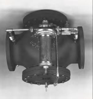
2 ROSS DOUBLE ACTING ALTITUDE VALVE MODEL 40DAWR INSTALLATION The DOUBLE ACTING or two-way valve (installed in a line which is both supply and discharge) permits flow into and discharge from tank, reservoir or basin. It automatically closes to prevent overflow and opens for reversal of flow when head in distribution is less that static head of water in tank. The stem of this valve has no throttling action because it assumes only two positions, wide open and closed. However, with the tank full or nearly so and with negligible system demand, the valve may assume an intermediate position until either a definite filling or emptying trend occurs. SHIPMENT: The valve is tagged with all necessary identification marks before shipment. Each valve is thoroughly tested and pre-adjusted at the factory to expected field conditions. STORAGE: If necessary to store the valve before installation, it should be protected from the elements. Inside storage is recommended. If this is not possible, the valve should be protected from dirt, heat, freezing, and direct sunlight. If extended storage is anticipated, the valve should be placed with the piston in the vertical plane (all valves are shipped in this orientation). MAIN VALVE INSTALLATION: 1. Check inside of the valve for wooden shipping blocks, or other foreign material. 2. If possible, flush line before inserting valve. 3. Place valve in line with flange marked "tank side" towards the tank or basin; and flange marked inlet toward the distribution or supply source. 4. If external piping and controls are not attached to valve when shipped, connect unions identified with numbered tags. 5. Attach 1/4" gauge cocks to body taps on back side of valve. CAUTION: Do not obstruct the vent hole in center of bottom cap (16) of globe body, or in differential cylinder bracket (27) of angle body. 6. Allow enough clearance above the valve for piston removal. STARTING OPERATION: 1. Fill tank by means of by-pas gate valve (if there is a by-pass). 2. Open the main line gate valve (if installed) on the tank (downstream) side of the valve. This prevents trapping high inlet pressure under the pilot diaphragm. 3. Open main line gate valve (if installed) on the inlet side of the valve slowly. 4. Open isolation ball valves (18) in control piping and the main valve will close. Note: This procedure will protect the external controls from fouling with the initial passage of water which may carry sediment. To increase the maximum water elevation, turn the pilot valve adjusting screw clock-wise; and to lower the water elevation, turn adjusting screw counter-clock-wise. For most elevated tank pressures one full turn of the adjusting screw will change the operating point approximately 7 feet. For low basin and ground storage pressures, one turn changes the operating point approximately 2 feet. ROSS VALVE MFG. CO., INC., TROY, NY PHONE FAX 518/


3
4 GENERAL OPERATION OF A ROSS VALVE (Models 30AWR and 40DAWR) All Ross Valves operate with the same basic hydraulic principles and are composed of two essential parts: the main valve (through which the main flow of water passes), and a control device (which is piped externally on the main valve). The control device is varied to suit the specific type of operation desired. In this case, it is a hydraulically actuated, non-throttling pilot valve. As always, the basic function is to control the pressure in the "operating chamber" (the area above the large piston in the main valve). The main valve, no matter what its function, is of the same fundamental design. A stem, which carries a seat disc between a large and a small piston, is free to move along the axis of the cylinders. This movement corresponds to the opening and closing of the valve, as follows: Opening - When the operating chamber is emptied (through a pilot valve, for example), the line pressure acts on the exposed areas of the stem and produces a net upward hydraulic force. This force lifts the stem assembly (including the seat disc), and allows water to flow unrestricted through the valve. Closing - When the setting on the pilot valve becomes satisfied (upon indication of a full tank, for example), its internal porting exposes the operating chamber to inlet pressure. As the pressure in the operating chamber builds up, the stem assembly is forced to move down into its seat, preventing flow through the valve. These are the basic principles used in all of our valves. ROSS VALVE MFG. CO., INC. - P.O. BOX 595, 6 OAKWOOD AVE. - TROY, NY TEL (518) FAX (518)
5 6 OAKWOOD AVENUE - TROY, NEW YORK, TEL. (518) POST OFFICE BOX TROY, NEW YORK, FAX (518) WEBSITE: sales@rossvalve.com 40DAWR 9/6/00 RJC 33 Model 40DAWR DOUBLE ACTING ALTITUDE VALVE
6 6 OAKWOOD AVENUE - TROY, NEW YORK, TEL. (518) POST OFFICE BOX TROY, NEW YORK, FAX (518) WEBSITE: - E-MA L: sales@rossvalve.com 40DAWR-F-N_ TJS 33 Model 40DAWR DOUBLE ACTING ALTITUDE VALVE
7 DIMENSIONS Globe Body Minimum Clearances Piston Valve Sizes: 4-36 Size (Inches) O P 4 1 /2 5 1 /2 6 1 / Note 1. Dimension O is clearance for removal of the top cap and piston for repacking the main valve. Additional working space for the convenience of the service man should be considered above as well as around the valve. 2. Dimension P as listed is the desirable clearance under the valve for removal of the STANDARD bottom cap. This dimension may be reduced to 1 inch for all valves on special applications. Note A. Do not obstruct vent hole located at the center of the bottom cap. B. Consideration should be given for installation of valves 14 or larger under manhole in the roof of the valve vault or for additional clearance above the valve since a mechanical hoist will probably be required for removal of the piston. An eye bolt or hook cast in the cover slab over the center of the valve is useful. C. If clearance under the valve is limited, dimensions O and P can be modified. Consult the factory concerning special applications.
8
9
 from the top and passes out through the sides of the cylinder. 2.")
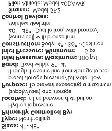
10 Sizes: ½ 1 Located: On any external piping Purpose: To protect external piping and control devices from fouling or damage from foreign particles Screen: Cylindrical Dutch weave stainless steel wire mesh Piping Connection: Standard pipe thread Operation 1. Water enters the cylindrical screen (#2) from the top and passes out through the sides of the cylinder. 2. Any particle too large to pass through.012 inch openings gets trapped in the cylinder, where, unless there is unusual turbulence, they settle at the bottom. Recommendation 1. Strainer should be blown down frequently to remove collected foreign material from the sediment chamber. 2. Strainer screen should be removed occasionally for inspection and thorough cleaning. PARTS FLOW 1. Body Bronze 2. Screen Stainless Steel 3. Cap Gasket Rubber 4. Cap Brass 5. Flushing Cock Brass Note 1. To clean without shutting down the line, open the flush cock (#5) in the bottom cap (#4) for several seconds. 2. To remove the screen (#2), which requires shutting down the line, unscrew the bottom cap assembly (#5). Model Number: 5F-2 Option Two strainers installed in parallel (with the appropriate isolation valves) to permit uninterrupted service while cleaning. Sizes: One size fits all piston valves Primarily Controlled By: Manually Adjusted Located: On external control circuit of the main valve Purpose: To limit flow in and out of the operating chamber Standard Shipped Adjustment: Course Needle: 5/6 to 2 turns off the seat Fine Needle: Based on individual specifications PARTS 1. Lock Brass 2. Cap Bronze 3. Cap Gasket Rubber 4. Needle Brass 5. Body Bronze Operation The simple construction reliably limits maximum flow through the external piping, depending on the position of the adjustable stem/needle (#4) relative to the seat. 1. When the needle (#4) is adjusted counter-clockwise to a raised position, a. More water can pass through the needle valve. b. Water enters (leaves) the operating chamber more quickly. c. The main valve piston moves up and down more quickly. 2. When the needle (#4) is adjusted clockwise to a lowered position, a. Less water can pass through the needle valve. b. Water enters (leaves) the operating chamber more slowly. c. The main valve piston moves up and down more slowly. Adjustment To adjust needle valve, which can be done without shutting down the main valve: 1. Remove the hex cap (#2) and lock(#1). 2. With a screw driver; a. Turn the needle (#4) counter-clockwise to raise it b. Turn the needle (#4) clockwise to lower it 3. Once the optimum position is determined, no further adjustment of the needle should be required. Note It is advisable to occasionally remove the cap (#2) and lock (#1) and change the position of the needle (#4) momentarily to insure against gradual plugging. Option Two separate needle valves on one main valve Provides independent control of opening and closing speeds.
11
12
13 ROSS GLOBE VALVE PREVENTIVE MAINTENANCE Intervals of inspection vary from valve to valve. Type of valve, quality of water being handled, rates of flow, operating pressures, and past maintenance practices all have a bearing on the length of service between overhauls. So some recommendation may guide the operator, we suggest periodic inspections in order to check for proper valve operating pressures, as well as any visual leaks. Should the operator encounter any external leakage, or find any abnormalities in the operating pressures resulting from the operation of the valve, the valve should be scheduled for service. EVERY TWO (2) MONTHS: 1. Flush the strainer via the flushing cock. 2. Flush the needle valve by turning then needle clockwise ½ turn, counter-clockwise 2 turns, then clockwise 1-1/2 turns to original setting. 3. Visually inspect for leaks around the indicator rod, bottom cap/differential vent hole, or pilot valves (hydraulic & /or solenoid). 4. Inspect drain line connection. EVERY FOUR (4) MONTHS: 1. Remove and inspect strainer screen. 2. Remove and inspect needle valve, being sure to take note of the needle position away from the seat (number of turns). 3. Same visual inspection as above. Important: Condition of the main valve packing can be accurately gauged by observing the leakage through the bottom vent hole C. Negligible leakage usually indicates serviceable packing. Lubrication: None Required. Spare Parts: None required, recommended, or supplied unless specified. Under normal operating conditions, no spare parts would be necessary within five (5) years of service. The standard repair kit for Ross valves are in stock at the factory, and available for immediate shipment upon receipt of order with valve serial number (located on metal tag pinned to the top cap of the main valve). ROSS VALVE MFG. CO., INC., TROY, NY PHONE FAX 518/
14 VALVE LOCATION/I.D. ROSS GLOBE VALVE INSPECTION - SERVICE RECORD SIZE MODEL SERIAL NO. VALVE - OPEN ~ CLOSED ~ INDICATOR ROD EXPOSED MAIN VALVE OPERATED MANUALLY YES ~...NO ~ OPERATING PRESSURES - INLET (SUPPLY) INCHES ABOVE STUFFING BOX CAP OUTLET (DOWNSTREAM) EXTERNAL LEAKS... NONE... SLIGHT... MAJOR...INDICATOR STUFFING BOX... ~... ~... ~...BOTTOM CAP VENT HOLE... ~... ~... ~...DIAPHRAGM VENT-HYDRAULIC PILOT... ~... ~... ~...SOLENOID PILOT EXHAUST PORT... ~... ~... ~ OTHER CONDITIONS STRAINER FLUSHED... YES ~... NO ~...SCREEN EXAMINED. YES ~... NO ~... CLEANED ONLY ~...SCREEN CONDITION GOOD ~... POOR ~...INSTALLED NEW SCREEN ~ NEEDLE VALVE(S) (EXAMINE NEEDLE & SEAT FOR WEAR)...OPENING CONTROL. CLEANED ~...ADJUSTED ~...SET POINT...CLOSING CONTROL...CLEANED ~...ADJUSTED ~...SET POINT HYDRAULIC PILOT ADJUSTED... NO ~... YES ~... TURNS...CLOCKWISE ~.. COUNTER-CLOCKWISE ~...SET POINT...REBUILT...AT FACTORY DATE. IN FIELD DATE...NEW HYDRAULIC PILOT REPLACEMENT...DATE SOLENOID - COIL TESTED... NO ~... YES ~...REPLACED ~...SEATS - INSPECT & CLEAN...REBUILT...AT FACTORY DATE...NEW SOLENOID REPLACEMENT MAIN VALVE INTERNAL CONDITION -...MAIN CYLINDER (14)...BOTTOM CAP CYLINDER (23)...SEAT DISC/SUPPORT/RING...BODY TAP CONNECTIONS...MAIN VALVE REPACKED ACTION RECOMMENDED...DATE. IN FIELD DATE DATE REPORT BY DATE ROSS VALVE MFG. CO., INC., TROY, NY PHONE FAX 518/
15 TROUBLE SHOOTING - ALTITUDE VALVES The first step in trouble shooting is to determine if the problem is related to the controls or to the main valve. Therefore, we must isolate the controls from the main valve. Observe indicator rod - is valve open or closed? When closed, approximately 1-1/4" of indicator rod shows above packing nut on stuffing box. (Most failures are in the open position.) Observe any external leakage from pilot waste port. The only time water should discharge is when the valve is moving from the closed to the open position. All other times there should be no waste. If the valve is closed and waste occurs, the lower seat on the pilot is fouled or damaged. If the valve is open, the upper pilot seat could be fouled or damaged OR the main cup plate assembly inside the main valve could be leaking. Close both ball valves in the control piping. If the leak stops, then the lower pilot seat is leaking. If the leak continues, separate the union at the top cap and see if water comes from the top cap connection. If no external leakage is evident, separate the union where the pilot pipe enters the top cap. If there is no water at the union, turn the adjusting screw on the pilot counterclockwise (out) SLOWLY until a trickle of water comes out the pilot pipe. The pilot is now adjusted to close the valve at the water level presently in the tank. Reconnect the union and tighten, and the main piston should slowly close. If no movement occurs after several minutes (pinch the indicator rod where it enters the stuffing box packing nut to feel slight movement), check to see if the vent hole in the center of the bottom cap is plugged. This will prevent the piston from moving. If no movement towards the closed position occurs, and pressure is available at the top cap union, the main piston seals may not be working and the valve should be disassembled. If the valve closes part way and stops, it usually means a foreign object is blocking the main piston, or the main cups have lost their seal - usually due to a wear spot in the main cylinder (main bushing). Again, valve disassembly is required. ROSS VALVE MFG. CO. INC. - 6 OAKWOOD AVE, TROY, NY / FAX
16 TROUBLE SHOOTING GUIDE Condition of the main v alve packing can be a ccurately gauged by o bserving t he l eakage through vent bole "C" in the bottom cap. Negligible leakage usually indicates serviceable packing. If there is cons tant waste from the pilot e xhaust when the valve is closed, the lower seat on the Pilot Valve is scored o r fouled (see A-2 below). If there is constant waste from the pilot exhaust when the valve is open, disconnect the union where the control pipe enters the top cap. I f the leakage originates in the main valve (through the cup plate bolts, or past the lower (Part No. 13) Main Cup, it will be obvious. If the pilot continues to waste water, it indicates a defective pilot valve. Return the pilot to the factory for repairs. A. When valve does not close, resulting in overflow of tank. First check to see if there is pressure in valve top cap (see adjustment - Page 4). Cause 1. Correction Cause 2. Cause 3. Incorrect adjustment of the pilot. Turn adjusting screw on pilot valve counter-clockwise until valve closes (See adjustment page 4). Pilot stem and seats are fouled (noted by continual waste from pilot). Flush pilot while main valve is open. Close isolation valves in the outer control piping. Remove cap (Part No. 20) at the bottom of the pilot. Remove stem (Part No. 19) and clean thoroughly. Before replacing, flush body of pilot by opening the control piping isolation valve nearest inlet flange of Main Valve. If scoring or damage to either the Ball Seat at the top of the stem or the Beveled Seat in the center is evident, the pilot should be returned to the factory for repair. Temporary relief may be obtained by lapping the damaged seats with lapping compound. Excessive leakage around Indicator Rod. Replace stuffing box packing and indicator rod. Cause 1. Cause 2. Cause 3. Cause 4. Cause 5. Cause 6. Cause 7. B. When valve will not fill tank or remains closed. Check to see if a minimum of 5 PSI line pressure is shown at system side body tap Incorrect adjustment of the pilot. Turn adjusting screw on pilot valve clockwise until valve opens (See adjustment page 4). Leakage into chamber "K" because of worn main cup leathers (Part No. 13) or loose bolts in their assembly (noted by continual waste from pilot). Leakage past worn main cup leather or loose bolts may be detected while main valve is open, by opening coupling connection at top of main valve. Leakage into chamber "K" because seat of upper stem in pilot is fouled or pilot packing leaks. Flush pilot - close isolation valves "G" and "GG", remove bottom cap of pilot, withdraw lower stem (Part No 19) and crack the isolation valve "GG" nearest inlet flange of main valve - examine and clean lower stem and replace with care. Stretched diaphragm. Replace. Worn packing in pilot. Replace. Fouled or leaking Swing Check Valve (Part No. 27). Close control piping isolation valves, remove pilot, open system side control piping isolation valve to observe leak. Clean or replace check valve. Leaking Check Valve in control piping. Clean or replace. C. Hunting or partial opening of main stem. Cause 1. Cause 2. Cause 3. Fictitious static head of water elevation due to head loss is sensed by the diaphragm of pilot from discharge sid of valve. This is usually caused by an appreciable run of pipe (or several fittings) between the valve and tan. basin. This condition is especially evident when the system pressure exceeds the tank head by 20 PSI or mor when the valve is closed. Close tank side control piping isolation valve and pipe separate sensing line from Tee (after removing plug) t riser of elevated tank or stand-pipe, or some point where the true static tank head is available. Fictitious static head communicates to diaphragm of pilot from distribution or supply side of valve. Look for line surges or partially closed gate valve on distribution or supply side of valve. In certain systems where the demand is very mall, or where the demand is being supplied primarily by oth( sources, it is normal for the valve to open only partially. This condition may be tested by opening a hydrant near the valve on the system side. D. Tank overflows, but the valve position indicator shows the valve is closes Cause 1. Cause 2. Worn seat packing (Part No. 9). Replace all internal main valve packing (Part No.'s 5, 9 and 13). Order as a repair kit for valve serial number. Worn seat disc (Part No. 8 and 24). Replace.
17 REPAIR INSTRUCTIONS - GLOBE BODY VALVES When entering a valve pit to inspect a valve, all regulations regarding Confined Space Entry should be observed. So some recommendation may guide the operator, we suggest periodic inspections in order to check for proper valve operating pressures as well as any visual leaks. Should the operator encounter any external leakage or find any abnormalities in the operating pressures which appear to be caused by the valve, the valve should be scheduled for service. A reliable indication of internal packing condition can be obtained by observing any leakage from the vent hole in the center of the bottom cap. When leakage becomes significant, packing replacement should be made. As a general statement, the overall average life of a set of packings is 7 to 10 years. This may vary considerably because of specific operating conditions. After observing pressures and inspecting for external leakage, the flush cock on the strainer should be opened momentarily to remove accumulated material. The needle valve cap should be removed and the needle closed 1/2 turn, opened 1 full turn, and then closed 1/2 turn to its original position. STEPS FOR INTERNAL REPAIRS: All repairs and parts replacement may be made without removing the valve from the line. Internal repairs are made by removing the top cap of the valve. All internals are accessible through the top. Shut inlet main line isolation valve, then shut outlet main line isolation valve. Open gauge cocks to de-pressurize the valve. Remove indicator rod by inserting a nail through hole and unscrewing. Do not pull through stuffing box. Then remove top cap bolts and top cap. Be careful not to bend indicator rod. In 8" and larger valves, withdraw piston by either removing two 3/8" bronze bolts in top stem nut and installing lifting device (horseshoe shaped piece of steel with two holes) over nut; or by looping a cable or nylon rope around these bolts. Be sure lifting device is secure before removing piston. In 4" and 6" valves, a threaded eyebolt should be screwed in the indicator rod hole. Inspect both main bushing (Part No. 14) and bottom cylinder (Part No. 23) for mineral build-up or scoring. Smooth with emery or replace if necessary. Inspect seat ring for damage. Repair as necessary. Secure main piston on a pipe threading stand (or lay piston on floor on rags or a similar cushioning material). Loosen top stem nut (Part No. 15) which holds the cup plate assembly. Remove cup plate bolts, nuts and copper washers on 8" cups and larger. Replace the leather cups (one faces up, one faces down). Re-install with new packings in the reverse order as outlined above. Caution - The clamping bolts should be tight so that the packings are held securely and no leak occurs. Do not over-tighten so that the packing is deformed, however. All cup packings are impregnated with lubricants so that no external lubrication is necessary or desirable. To replace the seat packing, it is necessary to determine if the valve is constructed with a "sliding" or a "flat" type seat. The sliding type seat has the seal or seat packing clamped in the valve body underneath the iron wall that separates the inlet and outlet valve chambers. It consists of a flanged packing held in place by a split bronze seat support ring. The lip of the packing "looks down" and care should be taken that the packing is concentric with the valve bore before the clamping bolts are tightened. In the "flat" type seat, the seat packing is located on the valve piston, where it is clamped between two plates and held by a stem nut (Part No. 7). Removal of this nut allows the plates to be separated and the packing replaced. Replacement of the bottom cups (Part No. 5) is accomplished by removing the bottom stem lock nut (Part No. 6) and the flanged bottom guide nut (Part No. 3). Install the seals with the lip of both cups "looking up". Again, when re-assembling, be careful not to over tighten so that the cups are deformed. Re-insert the piston being careful not to crimp the lower main cup when it enters the main bushing. The piston should move freely and drop of its own weight. Replace the top cap and control piping (being sure to thread in the indicator rod), then restore water pressure. Be sure to open the discharge isolation valve first so that high inlet pressure is not trapped against a closed outlet valve. All replaceable packings and gaskets are stock items and may be ordered as a repair kit for valve serial number. They are available for regular UPS delivery or next day service. All spare parts are available from: Ross Valve Mfg. Co., Inc., 6 Oakwood Avenue, Troy, New York, Phone: (518) , Fax: (518) H:\WP Version 8\Repair Instructions\Large Valve\WI1311_Rev. A - Large Globe Valve.wpd - Effective Date:
18 Piston Assembly Upper Middle A J D C B D K F Stem 5 E 4 G H 23 E E 6 L
SUBMITTAL NOTES PROJECT: Ross Model 50RWR-A Pilot Operated Surge Relief Valve with Hydraulic Anticipation. Size: inch / mm
 SUBMITTAL NOTES PROJECT: Ross Model 50RWR-A Pilot Operated Surge Relief Valve with Hydraulic Anticipation Size: inch / mm Every Ross Valve shall be hydrostatically tested for body integrity and tight seating
WW-730. Pressure Sustaining/Relief Control Valve
 WW-730 Pressure Sustaining/Relief Control Valve Installation Operation & Maintenance Page 1 of 6 1. DESCRIPTION The Model 730 Pressure Relief / Sustaining Valve is an automatic control valve designed to
WW-720. Pressure Reducing Control Valve
 WW-720 Pressure Reducing Control Valve (Size Ranges: 2-4 and 6-14 ) Installation Operation & Maintenance Page 1 of 6 1. DESCRIPTION The Model 720 Pressure Reducing is an automatic control valve (powered
WW-720. Pressure Reducing Control Valve
 WW-720 Pressure Reducing Control Valve (Size Ranges: 2-4 and 6-14 ) Installation Operation & Maintenance Page 1 of 6 1. DESCRIPTION The Model 720 Pressure Reducing is an automatic control valve (powered
Installation Operation Maintenance. Bermad Level Control Valve with Modulating Horizontal Float Pilot valve One Way Flow IOM.
 Bermad Level Control Valve with Modulating Horizontal Float Pilot valve One Way Flow Model: FP 450-80 Installation Operation Maintenance PAGE 1 OF 5 1. Safety First BERMAD believes that the safety of personnel
Operation & Maintenance Manual Place this manual with valve or person responsible for maintenance of the valve
 Operation & Maintenance Manual Place this manual with valve or person responsible for maintenance of the valve Model CYCLE GARD II, CI & CNA YOUR PRODUCT INFORMATION: Model Number: Date: Serial Number:
TECHNICAL DATA. Page 1 of 12
 Page 1 of 12 1. DESCRIPTION The Viking Regulating Valve is a direct-acting, single-seated, spring-loaded diaphragm valve. When installed as a pilot regulating valve on a Viking Model H or J Flow Control
TECHNICAL DATA. Pressure Regulation 531a. April 24, 2009
 April 24, 29 Pressure Regulation 531a 1. DESCRIPTION The Viking Regulating Valve is a direct-acting, single-seated, spring-loaded diaphragm valve. When installed as a pilot regulating valve on a Viking
Type S301 & S302 Gas Regulators INTRODUCTION INSTALLATION. Scope of Manual. Description. Specifications. Type S301 and S302. Instruction Manual
 Fisher Controls Instruction Manual Type S301 & S302 Gas Regulators October 1981 Form 5180 WARNING Fisher regulators must be installed, operated, and maintained in accordance with federal, state, and local
TECHNICAL DATA CAUTION
 Page 1 of 12 1. DESCRIPTION The Viking Model C-2 Pilot Pressure Regulating Valve is a direct-acting, single-seated, spring-loaded diaphragm valve. When installed as a pilot regulating valve on a Viking
Installation Troubleshooting Maintenance Instructions Installation / Start-up
 Model ZW207 Installation Troubleshooting Maintenance Instructions Installation / Start-up NOTE: Flushing of all pipe lines is to be performed to remove all debris prior to installing valve. 1. For making
Assembly Drawing: W-311B-A01, or as applicable Parts List: W-311B-A01-1, or as applicable Special Tools: , , &
 REDQ Regulators Model 411B Barstock Design Powreactor Dome Regulator OPERATION AND MAINTENANCE Contents Scope..............................1 Installation..........................1 General Description....................1
Model: 720-UL INSTALLATION OPERATION MAINTENANCE. Bermad Pressure Reducing Valve IOM. Model: FP -720-UL Sizes: 2"-12" BERMAD. Application Engineering
 Bermad Pressure Reducing Valve Model: 720-UL INSTALLATION OPERATION MAINTENANCE Application Engineering BERMAD 1. Safety First BERMAD believes that the safety of personnel working with and around our equipment
RS(H)10,15 USER MANUAL. Read the complete manual before installing and using the regulator.
10,15 USER MANUAL. Read the complete manual before installing and using the regulator.") RS(H)10,15 USER MANUAL Read the complete manual before installing and using the regulator. WARNING INCORRECT OR IMPROPER USE OF THIS PRODUCT CAN CAUSE SERIOUS PERSONAL INJURY AND PROPERTY DAMAGE. Due to
RS(H)10,15 USER MANUAL Read the complete manual before installing and using the regulator. WARNING INCORRECT OR IMPROPER USE OF THIS PRODUCT CAN CAUSE SERIOUS PERSONAL INJURY AND PROPERTY DAMAGE. Due to
BUTTERFLY VALVES Series 800
 BUTTERFLY VALVES Series 800 WARNING Before proceeding read ALL instructions and become familiar with the equipment and associated drawings. Follow ALL applicable safety regulations and codes for pressurized
1805 Series Relief Valves
 Instruction Manual Form 1211 1805 Series October 2011 1805 Series Relief Valves! WARNING Failure to follow these instructions or to properly install and maintain this equipment could result in an explosion
SINGER MODEL 106/206-RPS-L&H
 DESCRIPTION: Model 106/206-RPS-L&H dissipates surges caused by power failure to pumps. The valve anticipates the surge by opening on low line pressure associated with sudden stopping of pumps. This assures
Regulator from 1800 B series
 Regulator from 1800 B series Regulator from 1800 B series Measuring of industrial gases frequently requests a precise pressure regulation for the purpose of dosage and proccesing. UNIS FAGAS has two kinds
Types 749B and R130 Changeover Manifolds
 Instruction Manual MCK-1179 Types 749B and R130 June 2012 Types 749B and R130 Changeover Manifolds TYPE HSRL-749B TYPE 64SR/122 TYPE R130/21 TYPE 749B/21 Figure 1. Changeover Manifolds and Regulator Assemblies
Installation, Operation and Maintenance Manual for Back Pressure Regulator
 Installation, Operation and Maintenance Manual for Back Pressure Regulator Model 8860 2009 Groth Corporation IOM-8860 Rev. B 12541 Ref. ID: 95565 Page 2 of 13 Table of Contents I. INTRODUCTION 3 II. DESIGN
Model 420-HY Pressure Regulating Hydrant Valve
 Model 420-HY Pressure Regulating Hydrant Valve INSTALLATION OPERATION MAINTENANCE 1. Safety First BERMAD believes that the safety of personnel working with and around our equipment is the most important
Welker Sampler. Model GSS-1. Installation, Operation, and Maintenance Manual
 Installation, Operation, and Maintenance Manual Welker Sampler Model GSS-1 The information in this manual has been carefully checked for accuracy and is intended to be used as a guide to operations. Correct
Bray/ VAAS O-Ported Series Knife Gate Valve 770/780 Series Operation and Maintenance Manual
 Bray/ VAAS Knife Gate Valve 770/780 Series Operations and Maintenance Manual Table of Contents Definition of Terms 1 Safety Instructions 1 Introduction 2 Unpacking 2 Storage 2 Installation 2 Commissioning
Operating instruction
 Operating instruction MV, XV, HG, HP, RKO, D2G, TV, BV, WB & SLV 1 Introduction 2 2 Stafsjö s knife gate valves 2 3 Technical information 2 3.1 Pressure test 2 3.2 Labelling 2 4 Storage 3 5 Transportation
1200B2 Series Service Regulators. Instruction Manual
 00B Series Service Regulators Instruction Manual 00B Series Service Regulators 0 Elster American Meter 00B Series Service Regulators General Information The 00B Series Service Regulators are available
Hydraulic Piston Accumulators
 Ride Control Engineering Services PWCE Extendavator Paul Wever Construction Equipment Co., Inc. P.O. Box 85 401 Martin Drive Goodfield, IL 61742-0085 Phone (309) 965-2005 Fax (309) 965-2905 1-800-990-PWCE
Model GP PRESSURE REDUCING VALVE Installation & Operation Manual
 Model GP-2000 PRESSURE REDUCING VALVE Installation & Operation Manual Please read this bulletin thoroughly before using the pressure reducing valve, so that you may do so correctly and safely. Please carefully
Bermad Pressure Reducing. Model: 42T
 Bermad Pressure Reducing Pilot Operated Pressure Control Valve Model: 42T Installation Operation Maintenance Manual (IOM) REV. 27.7.17 Page 1 of 12 Safety First BERMAD believes that the safety of personnel
Pressure Dump Valve Service Kit for Series 2300 Units
 Instruction Sheet Pressure Dump Valve Service Kit for Series 00 Units. Overview The Nordson pressure dump valve is used to relieve hydraulic pressure instantly in Series 00 applicator tanks when the unit
V43 Pressure Actuated Water Regulating Valve
 FANs 125, 121 Product/Technical Bulletin V43 Issue Date 0996 V43 Pressure Actuated Water Regulating Valve The V43 Pressure Actuated Water Regulating Valves are designed to regulate water flow for water-cooled
CAST IRON VALVES FLOAT VALVE
 CAST IRON VALVES FLOAT VALVE NETAFIM CAST IRON VALVES FLOAT VALVE INLINE 25-400MM ANGLE 50-100MM SPECIFICATIONS Manufactured to ISO 9001 Available Valve sizes INLINE Flanged 50mm to 600mm & Threaded 19mm
TECHNICAL DATA Q = C. v P S. 2 Model G-2000 Dry valve. Page 1 of 13
 Page 1 of 13 1. Description The Viking 2 Model G-2000 Dry Valve Riser Assembly consists of a small profile, light weight, pilot operated valve that is used to separate the water supply from the dry sprinkler
TBV OPERATION AND MAINTENANCE MANUAL SERIES 2800: FLANGED BALL VALVE. For technical questions, please contact the following:
 TBV OPERATION AND MAINTENANCE MANUAL SERIES 2800: FLANGED BALL VALVE For technical questions, please contact the following: Engineering Department 1537 Grafton Road Millbury, MA 01527 Phone: (508) 887-9400
TECHNICAL DATA 3 MODEL G-3000 DRY VALVE RISER ASSEMBLY
 Page 1 of 13 1. DESCRIPTION The Viking 3 Model G-3000 Dry Valve Riser Assembly is equipped with a small profile, light weight, pilot operated valve that is used to separate the water supply from the dry
Needle valve. Contents. User s Manual. (1) Be sure to read the following warranty clauses of our product 1. (2) General operating instructions 2
 Be sure to read the following warranty clauses of our product 1. (2) General operating instructions 2") Serial No. H-V024-E-7 Needle valve User s Manual Contents (1) Be sure to read the following warranty clauses of our product 1 (2) General operating instructions 2 (3) General instructions for transportation,
Serial No. H-V024-E-7 Needle valve User s Manual Contents (1) Be sure to read the following warranty clauses of our product 1 (2) General operating instructions 2 (3) General instructions for transportation,
TECHNICAL DATA. Q= Cv S
 Page 1 of 13 1. DESCRIPTION The Viking 4 inch Model G-4000 Dry Valve Riser Assembly consists of a small profile, light weight, pilot operated valve that is used to separate the water supply from the dry
MODEL 200 KNIFE GATE VALVES INSTALLATION & MAINTENANCE MANUAL
 MODEL 200 KNIFE GATE VALVES INSTALLATION & MAINTENANCE MANUAL Index 1. List of components / General arrangement 2. Description 3. Handling 4. Installation 5. Actuators / Operation 6. Maintenance a. Changing
TECHNICAL DATA CAUTION
 Page 1 of 6 1. DESCRIPTION The Viking Model D-2 Accelerator is a quick-opening device, with an integral anti-flood assembly, used to increase the operating speed of a differential type dry pipe valve.
Reduce pressure zone device suitable for high and medium hazard rated applications Flanged end connections
 VALVCHEQ Backflow Preventers Reduce pressure zone device suitable for high and medium hazard rated applications Flanged end connections Features General application The RP03 provides protection from both
TECHNICAL DATA. Q = C v P S
 Page 1 of 13 1. DESCRIPTION The Viking 6 Model G-6000 Dry Valve Riser Assembly consists of a small profile, light weight, pilot operated valve that is used to separate the water supply from the dry sprinkler
OPERATING AND MAINTENANCE MANUAL
 Series 4300 Engineered Performance TABLE OF CONTENTS 0 INTRODUCTION 1 1 Scope 1 2 Description 1 3 Specifications 1 0 INSTALLATION 1 1 Mounting 1 2 Piping 1 1 Connecting Process Pressure 2 2 Vent Connections
1800C and 1800C-HC Series Service Regulators
 1800C and 1800C-HC Series Service Regulators Installation Instructions www.elster-americanmeter.com General Information: The 1800C and 1800C-HC Regulators are available as Full Capacity Internal Relief
!!!! SERVICE MANUAL PRESSURE POT 2 GALLON. Service Manual: LT Washington St 931 Progress Ave., #7
 EXEL North America, Inc. EXEL Industrial Canada, Inc. 1310 Washington St 931 Progress Ave., #7 West Chicago, IL 60185 Scarborough ONT, M1G 3V5 Ph : (800) 573 5554 Ph : (800) 450 0655 Fx : (800) 664 1511
Model GPR Primary Pressure Regulating Valve. Instruction Manual
 Model GPR-2000 Primary Pressure Regulating Valve Instruction Manual Please read this instruction manual thoroughly before using the primary pressure regulating valve, so that you may do so correctly and
TECHNICAL DATA MAINTENANCE AIR COMPRESSOR MODEL G-1
 Dry 131h 1. DESCRIPTION The Viking Model G-1 Maintenance Air Compressor is an electric motor-driven, aircooled, single-stage, oil-less compressor. The unit is equipped with a check valve and provides a
D05 Pressure Regulating Valves
 D05 Pressure Regulating Valves FEATURES PRODUCT DATA Noncorroding unitized cartridge contains all working parts and is easily replaceable. Includes built-in strainer and thermal bypass. Balanced seat construction
Anderson Greenwood Series 93 Positive Pressure POSRV Installation and Maintenance Instructions
 Before installation these instructions must be fully read and understood Installation and maintenance instructions for Series 93 Positive Pressure Pilot Operated Safety Relief Valves (POSRV). The intent
KECKLEY INSTALLATION, OPERATING AND MAINTENANCE INSTRUCTIONS TYPE NO. 7 FLOAT VALVE
 INSTALLATION, OPERATING AND MAINTENANCE INSTRUCTIONS TYPE NO. 7 FLOAT VALVE APPLICATION/SERVICE: The NO. 7 internally piloted valves are recommended where tight closing is essential. The NO. 7 is most
EASTERN ENERGY SERVICES PTE LTD. 60 Kaki Bukit Place #02-19 Eunos Tech Park Singapore, SG Singapore Telephone: Fax:
 2 Table Of Contents 1. Introduction 3 2. About this Manual 3 3. Contacting YZ Systems 3 4. Vessel Components 4 5. Specifications 5 6. Application 6 7. Theory of Operation 7 8. DuraSite Installation & Use
Model: 43T. Bermad Pressure Relief Valve
 Model: 43T Bermad Pressure Relief Valve Installation Operation Maintenance Manual () Rev.C1_01.08.17 Page 1 of 10 Safety First BERMAD believes that the safety of personnel working with and around our equipment
VALVCHEQ BACKFLOW PREVENTERS FIGURE RP03
 Reduce pressure zone device suitable for high and medium hazard rated applications Flanged end connections FEATURES GENERAL APPLICATION The RP03 provides protection from both backsiphonage and backpressure
299H Series. Introduction. P.E.D. Categories. Specifications. Installation. Warning. Installation Guide English September 2012
 Installation Guide English September 2012 299H Series Introduction This Installation Guide provides instructions for installation, startup, and adjustment of 299H Series regulators. To receive a copy of
Speed control assembly model A-1
 Pressure Regulation 533a 1. DESCRIPTION The Viking Speed Control Assembly provides adjustment of the opening speed of Viking Deluge Valves, and adjustment of both the opening and closing speed of Viking
APCO ARV CLEAN WATER AIR RELEASE VALVES. Model 50A
 APCO ARV CLEAN WATER AIR RELEASE VALVES Model 50A Instruction D12013 February 2017 Instructions These instructions provide installation, operation and maintenance information for APCO ARV Clean Water Air
Model 7989T Steel Pipe Squeezer Sch. 40 & Sch. 80. Operations Manual
 10-12 Steel Pipe Squeezer Sch. 40 & Sch. 80 Operations Manual 1.0 Introduction This manual is issued as a basic operation manual covering the Regent Model 7989T, Pipe Squeezer and Pump as manufactured
AcornVac Vacuum Plumbing Systems - Trouble Shooting Guide
 AcornVac Vacuum Plumbing Systems - Trouble Shooting Guide 1. Accumulators Problem Accumulator is overflowing If Accumulator continues to overflow Correction 1. Push and hold the manual activation button
1305 Series Pressure Reducing Regulators
 Instruction Manual Form 1095 1305 Series October 2009 1305 Series Pressure Reducing Regulators! Warning Fisher regulators must be installed, operated, and maintained in accordance with federal, state,
Anti-flood device Model B-1
 December 4, 2009 Dry Systems 123a 1. DESCRIPTION The Anti-flood Device is required when Viking accelerators are installed on dry systems according to Viking Model E-1 Accelerator Trim Charts. In the SET
Atmospheric relief valve type 1100 Installation and maintenance instructions
 SAPAG 1. Description Sapag atmospheric relief valves type 1100 have been selected for installation because of their performance features, reliability and ease of maintenance. They are designed to protect
Mounting and operating instructions EB 2530 EN. Self-operated Pressure Regulator. Pressure Reducing Valve Type M 44-2
 Self-operated Pressure Regulator Pressure Reducing Valve Type M 44-2 Type M 44-2, connection G 1 4, K VS = 0.15 Type M 44-2, connection G 1, K VS = 6 Fig. 1 Type M 44-2 Pressure Reducing Valve Mounting
DelVal Flow Controls Private limited
 DelVal Flow Controls Private limited (A DIVISION OF DelTech CONTROLS LLC, USA) DelVal Series 50/5, 5A/5B Butterfly Valves INSTALLATION, OPERATION AND MAINTENANCE MANUAL ENGINEERING DATA SHEET E.D.S. NO
DS06D,G Dial Set Pressure Regulating Valve
 DS06D,G Dial Set Pressure Regulating Valve PRODUCT DATA FEATURES APPLICATION Built-in, factory-calibrated outlet pressure adjustment dial. Noncorroding unitized cartridge contains all working parts and
WHEATLEY WHEATLEY SERIES 500 SWING CHECK VALVE. Installation, Operation and Maintenance Manual
 WHEATLEY SERIES 500 SWING CHECK VALVE STANDARD INTEGRAL SEAT & OPTIONAL REMOVABLE SEAT 2" FP - 6" FP 150# - 1500# 8" FP - 12" FP 150# - 900# API 6D and B16.34 2" FP - 4" FP 5000# DRILLING PRODUCTION VALVE
64 Series Pressure Reducing Regulators
 Instruction Manual Form 1245 64 Series March 2006 64 Series Pressure Reducing Regulators W1943 Figure 1. 64 Series Regulator Introduction Scope of Manual This manual provides instructions for the installation,
LRS(H)4 USER MANUAL. Read the complete manual before installing and using the regulator.
4 USER MANUAL. Read the complete manual before installing and using the regulator.") LRS(H)4 USER MANUAL Read the complete manual before installing and using the regulator. WARNING INCORRECT OR IMPROPER USE OF THIS PRODUCT CAN CAUSE SERIOUS PERSONAL INJURY AND PROPERTY DAMAGE. Due to the
LRS(H)4 USER MANUAL Read the complete manual before installing and using the regulator. WARNING INCORRECT OR IMPROPER USE OF THIS PRODUCT CAN CAUSE SERIOUS PERSONAL INJURY AND PROPERTY DAMAGE. Due to the
WHEATLEY Series 500 Swing Check Valve
 Document Number: TC003001-13 Revision: 02 WHEATLEY Series 500 Swing Check Valve Installation, Operation, and Maintenance Manual TABLE OF CONTENTS BILL OF MATERIALS...3 SCOPE...5 INSTALLATION AND OPERATION
PRS(TC)4,8 USER MANUAL. Read the complete manual before installing and using the regulator.
4,8 USER MANUAL. Read the complete manual before installing and using the regulator.") PRS(TC)4,8 USER MANUAL Read the complete manual before installing and using the regulator. WARNING INCORRECT OR IMPROPER USE OF THIS PRODUCT CAN CAUSE SERIOUS PERSONAL INJURY AND PROPERTY DAMAGE. Due to
PRS(TC)4,8 USER MANUAL Read the complete manual before installing and using the regulator. WARNING INCORRECT OR IMPROPER USE OF THIS PRODUCT CAN CAUSE SERIOUS PERSONAL INJURY AND PROPERTY DAMAGE. Due to
Summary of Accumulators These operating instructions apply to the accumulators listed in the table shown below.
 Page 1 of 15 Summary of Accumulators These operating instructions apply to the accumulators listed in the table shown below. Model Number A25-XXXX-3.6K Series A40-XXXX-3K Series A40X-XXXX-3.6K Series A60-XXXX-3K
End Connection. Thread x Thread N/A N/A N/A N/A Flange x Flange N/A
 Worldwide Contacts www.tyco-fire.com Model RV-1 Pressure Relief Valve, Pilot-Operated, Globe and Angle Body Styles General Description Valves, through inch (DN50 through DN00), are factory assembled and
Model GP-1000 Series PRESSURE REDUCING VALVE. Installation & Operation Manual
 Model GP-1000 Series PRESSURE REDUCING VALVE Installation & Operation Manual Please read this bulletin thoroughly before using the pressure reducing valve, so that you may do so correctly and safely. Please
BERMAD Waterworks. Level Control Valve with Altitude Pilot. 700 Series. Model X. Features and Benefits. Major Additional Features
 Level Control Valve with Altitude Pilot High level reservoirs & water towers Energy cost critical systems Systems with poor water quality Inherent refreshing Level sustaining at reservoir outlet The Level
Halsey Taylor Owners Manual 4410 Freeze Resistant Tubular Fountain STOP!
 Halsey Taylor Owners Manual 4410 Freeze Resistant Tubular Fountain STOP! PLEASE READ THE FOLLOWING INFORMATION. ITALLATION ITRUCTIO FOR THE 4410FR FTN. WITH 97243C SINGLE VALVE CONTROL ASSEMBLY ARE LOCATED
KTM OM-2 SPLIT BODY FLOATING BALL VALVES INSTALLATION AND MAINTENANCE INSTRUCTIONS
 Before installation these instructions must be fully read and understood SECTION 1 - STORAGE 1.1 Preparation and preservation for storage All valves should be properly packed in order to protect the parts
TECHNICAL DATA. Q = C v P S
 January 6, 2012 Preaction 348a 1. Description Viking supervised Surefire Preaction Systems utilize the Viking G-6000P Valve. The small profile, lightweight, pilot operated Viking G-6000P Valve comes complete
TECHNICAL DATA. Q = C v P S
 January 6, 2012 Preaction 333a 1. Description Viking supervised Surefire Preaction Systems Utilize the Viking G-3000P Valve. The small profile, lightweight, pilot-operated Viking G-3000P Valve comes complete
TECHNICAL DATA ANTI-FLOOD DEVICE MODEL B-1 1. DESCRIPTION
 Page 1 of 6 1. DESCRIPTION The Model B-1 Anti-flood Device is required when Viking accelerators are installed on dry systems according to Viking Model E-1 Accelerator Trim Charts. In the SET condition,
Reduce pressure zone device suitable for high and medium hazard rated applications BSP screwed connections
 Reduce pressure zone device suitable for high and medium hazard rated applications BSP screwed connections Features General application The RP03 provides protection from both backsiphonage and backpressure
ROTATING DISK VALVES INSTALLATION AND MAINTENANCE 1. SCOPE 3 2. INFORMATION ON USAGE 3 3. VALVE TYPES 3 4. OPERATORS 5 5. VALVE CONSTRUCTION 6
 Sub Section INDEX Page Number 1. SCOPE 3 2. INFORMATION ON USAGE 3 3. VALVE TYPES 3 4. OPERATORS 5 5. VALVE CONSTRUCTION 6 6. INSTALLATION AND OPERATION 6 7. MAINTENANCE 8 8. REPAIR 9 9. ASSEMBLY 10 10.
DBML-60/80 Squeeze Tool
 DBML-60/80 Squeeze Tool OPERATORS MANUAL Description The Mustang Model DBML-60/80 Hydraulic squeeze tool has been manufactured since 1995. A Mustang 3 3/4 bore doubleacting cylinder producing 41,000 lbs
TECHNICAL DATA. Q = C v P S
 Preaction 346a 1. Description The 6 Model G-6000P Electric Release Preaction System Riser Assembly can be used as a Single Interlock Preaction System with Electric Release, or as a Double Interlock Preaction
INSTALLATION, OPERATION & MAINTENANCE MANUAL
 INSTALLATION, OPERATION & MAINTENANCE MANUAL AWWA C500 SOLID WEDGE GATE VALVE 2 72 NRS and OS&Y Series 100 and Series 105 TABLE OF CONTENTS SECTION PAGE # Equipment List 2 General 3 Receipt and Inspection
Hi-Force Limited Prospect Way Daventry Northants NN11 8PL United Kingdom Tel: +44(0) : Fax: +44(0) : Website:
 : Fax: +44(0) : Website:") 1.0 Inspection of the product upon receipt: On receipt of the product, visually inspect the item for any evidence of shipping damage. Please note shipping damage is not covered by warranty. If shipping
1.0 Inspection of the product upon receipt: On receipt of the product, visually inspect the item for any evidence of shipping damage. Please note shipping damage is not covered by warranty. If shipping
Apollo Standard Port, Full Port & One Piece Flanged Ball Valves Installation, Operation, & Maintenance Manual
 I854000.D Apollo Standard Port, Full Port & One Piece Flanged Ball Valves Installation, Operation, & Maintenance Manual Introduction This manual presents guidelines for the Installation, Operation and
Installation, Operation, and Maintenance Manual
 Installation, Operation, and Maintenance Manual Welker Instrument Supply Pressure System Model WIC The information in this manual has been carefully checked for accuracy and is intended to be used as a
Halsey Taylor Owners Manual STOP!
 Halsey Taylor Owners Manual 4710 Freeze Resistant Floor Mounted Steel Fountain STOP! PLEASE READ THE FOLLOWING INFORMATION. ITALLATION ITRUCTIO FOR THE 4710FR FTN. WITH 97243C SINGLE VALVE CONTROL ASSEMBLY
Types S100K and S102K Pressure Regulators
 Instruction Manual Form 5624 Types S0K and S2K 01/01 Types S0K and S2K Pressure Regulators W7478-1 Figure 1. Types S0K and S2K Pressure Regulator Introduction Scope of Manual This manual provides instructions
V48 Series 3-Way Pressure-Actuated Water-Regulating Valves With Union Fittings
 Installation Instructions V48 Issue Date 08/30/01 V48 Series 3-Way Pressure-Actuated Water-Regulating Valves With Union Fittings Application IMPORTANT: The V48 Series 3-Way Pressure-Actuated Water-Regulating
Pressure Dump Valve Service Kit for Series 3000 Units
 Instruction Sheet Pressure Dump Valve Service Kit for Series 000 Units. Overview The Nordson pressure dump valve is used to relieve hydraulic pressure instantly in Series 00, 400, 500, and 700 applicator
Discontinued. Powers Controls. Technical Instructions Document No P25 RV Rev. 1, May, RV 201 Pressure Reducing Valves.
 Powers Controls RV 201 Pressure Reducing Valves Description Features Product Numbers Dual Pressure PRV Technical Instructions Document No. 155-049P25 RV 201-1 Single Pressure PRV The RV 201 Pressure Reducing
TITAN FLOW CONTROL, INC.
 PREFACE: This manual contains information concerning the installation, operation, and maintenance of Titan Flow Control (Titan FCI) Simplex Basket Strainers. To ensure efficient and safe operation of Titan
KENNEDY VALVE OPERATION & MAINTENANCE MANUAL
 2 54 ROTATING DISC GATE VALVE OPERATION & MAINTENANCE MANUAL Rel. 5/27/16 1 TABLE OF CONTENTS 3 General 3 Receipt & Inspection 4 Gate Valve Storage & Handling 5 6 Installation 7 Operation 8 Field Testing
DS05C,D,G Dial Set Pressure Regulating Valves
 DS05C,D,G Dial Set Pressure Regulating Valves APPLICATION The Honeywell DS05C,D,G Dial Set Pressure Regulating Valve is a high quality pressure regulating valve that maintains a constant outlet pressure
V46 Series 2-Way Pressure-Actuated Water-Regulating Valves With Union Fittings
 Installation Instructions V46 Issue Date 11//1 V46 Series -Way Pressure-Actuated Water-Regulating Valves With Union Fittings Application IMPORTANT: The V46 Series -Way Pressure-Actuated Water-Regulating
OWNER S TECHNICAL MANUAL
 EL SERIES OWNER S TECHNICAL MANUAL DP7002 1 Air Operated Diaphragm Pump Description The DP7002 1 air operated diaphragm pump is the ideal device for the pumping, transfer and dispensing of chemical liquids,
Differential Pressure Regulator Type Type 45-6 (0.1 to 1 bar, DN 15) Mounting and Operating Instructions EB 3226 EN
 Mounting and Operating Instructions EB 3226 EN") Differential Pressure Regulator Type 45-6 Type 45-6 (0.1 to 1 bar, DN 15) Mounting and Operating Instructions EB 3226 EN Edition March 2008 Contents Contents Page 1 Design and principle of operation...................
Differential Pressure Regulator Type 45-6 Type 45-6 (0.1 to 1 bar, DN 15) Mounting and Operating Instructions EB 3226 EN Edition March 2008 Contents Contents Page 1 Design and principle of operation...................
SAPAG. Safety valves, type 5700 Storage, Use, Operation and Maintenance Instructions. IMPORTANT NOTICE
 SAPAG IMPORTANT NOTICE Contents Important notice 1 0 Valve identification 2 1 Storage 2 2 Installation 2 3 Operation 2 4 Maintenance 3 4.1 Dismantling 3 4.2 Inspection 3 4.3 Repair 3 4.4 Assembly 4 4.5
Type ACE95jr Tank Blanketing Valve
 Instruction Manual Form 5666 Type ACE95jr 04/01 Type ACE95jr Tank Blanketing Valve W8157 Introduction Scope of Manual Figure 1. Type ACE95jr Tank Blanketing Valve This instruction manual provides installation,
LRS(H)4 Pressure-Reducing Regulator User Manual
4 Pressure-Reducing Regulator User Manual") LRS(H)4 Pressure-Reducing Regulator User Manual Read the complete manual before installing and using the regulator. 2 Safe Product Selection When selecting a product, the total system design must be considered
LRS(H)4 Pressure-Reducing Regulator User Manual Read the complete manual before installing and using the regulator. 2 Safe Product Selection When selecting a product, the total system design must be considered
! WARNING. Model PFC-1-G (direct acting) PFC-1-GR (reverse acting) Modulating Pneumatic Liquid Level Controls INSTRUCTION MANUAL MM-110B
 PFC-1-GR (reverse acting) Modulating Pneumatic Liquid Level Controls INSTRUCTION MANUAL MM-110B") INSTRUCTION MANUAL MM-110B Model PFC-1-G (direct acting) PFC-1-GR (reverse acting) Modulating Pneumatic Liquid Level Controls APPLICATIONS: Use with other pneumatic devices, for liquid level sensing in
INSTRUCTION MANUAL MM-110B Model PFC-1-G (direct acting) PFC-1-GR (reverse acting) Modulating Pneumatic Liquid Level Controls APPLICATIONS: Use with other pneumatic devices, for liquid level sensing in
TECHNICAL DATA. Q = C v P S
 January 6, 2012 Preaction 331a 1. Description Viking supervised Double-Interlocked Electric/Pneumatic Release Preaction Systems utilize the Viking G-3000P Valve. The small profile, lightweight, pilot-operated