KECKLEY INSTALLATION, OPERATING AND MAINTENANCE INSTRUCTIONS TYPE NO. 7 FLOAT VALVE
|
|
|
- Bertram Goodwin
- 5 years ago
- Views:
Transcription
1 INSTALLATION, OPERATING AND MAINTENANCE INSTRUCTIONS TYPE NO. 7 FLOAT VALVE APPLICATION/SERVICE: The NO. 7 internally piloted valves are recommended where tight closing is essential. The NO. 7 is most commonly used to maintain a water level in a tank by means of the attached float linkage. By reversing the linkage, the NO. 7 may be set to either open or close on level rise. These valves are best suited for clean liquids not injurious to iron, brass or neoprene. MAXIMUM PRESSURE & TEMPERATURE LIMITS Pipe Size Pressure Temperature ½ and ¾ 130 lb /in 2 Standard neoprene disc is recommended for lb /in 2 1¼ 80 lb /in 2 1½ 65 lb /in lb /in 2 temps up to 125 F. Optional Teflon disc is available for temps from 125 F to 350 F CONSTRUCTION FEATURES: Valve sizes through 1½ are available only with threaded ends and an integral seat. These sizes are supplied standard with bronze body and trim. The 2 size is available in both threaded and flanged end connections with a replaceable seat. This 2 size is supplied standard with a cast iron body and bronze trim. Other materials are available (consult factory). All sizes of these valves are available in either a Globe (straight through) or Angle (side inlet-bottom discharge) configuration. INSTALLATION: Thoroughly clean dirt, slag, etc. from both the valve body and inlet pipe. Install the NO. 7 float valve near the water level you wish to maintain with the valve stem in a vertical position; rotate the swivel guide yoke so that the float rests in calm water. Turbulence in the tank should be avoided, as it will proportionally decrease the working life of any moving parts. If turbulence exists, it may be necessary to extend the piping down from the discharge side to a point well below the lowest level of water maintained. Stilling wells may also be used to dampen the effects of turbulence on the float. It is recommended that you install both a strainer and a shutoff valve on the inlet side of these valves. The strainer will keep debris from clogging the internal ports of these valves and the shutoff valve will allow for easy access to the valve should it need to be removed. The direction of flow through these valves should agree with the markings on the side of the valve body. These valves should be protected from freezing water both in the valve, and on the surface of the water. START UP: Open the upstream shut off valve gradually to permit the tank to fill slowly and to also allow time for the necessary adjustment of the float rod and linkage to obtain the desired maximum water level; then open the shut off valve completely. Precisely adjust the water level by changing the floats position. TROUBLES AND REMEDIES: Problem: Valve does not close tightly. Solution: 1. Check the inlet pressure gauge. Do not exceed the maximum allowable inlet pressure shown. 2. Disassemble valve and clean the seat and disc. Check for wear and replace the valve disc if needed. 3. Check that the maximum temperature for disc material is not exceeded. Problem: Valve sticks or leaks at stem. Solution: Stem packing may be too tight. Repack and tighten the gland only finger tight. Problem: Valve closes suddenly or chatters. Solution: 1. Check the size of the valve against the capacity (GPM) needed. Do not use an oversized valve. It is recommended that a valve have between 50% to 100% more capacity than the normal demand. 2. Weighting the float may slow the action. MAINTENANCE: The operation and condition of the valve should be checked at regular intervals. Keckley Company 3400 Cleveland Street P.O. Box 67 Skokie, IL Phone FAX
2
3 INSTALLATION OPERATING AND MAINTENANCE INSTRUCTIONS TYPE #77 FLOAT VALVE APPLICATION: The No.77 internally piloted valves are recommended where tight closing is essential. Each of these valves is available in either a GLOBE (straight through) or Angle (bottom inlet-side discharge) configuration. The No.77 is most commonly used to maintain a water level in a tank by means of the attached float linkage. These valves are best suited for clean liquids not injurious to neoprene, leather or brass. PRESSURE AND TEMPERATURE LIMITS: MAXIMUM PRESSURE & TEMPERATURE RATING Body Type Pressure Temperature Cast Iron or Bronze (NPT) 250 # 2 / in 125 F Cast Iron (Std. Flange) 200 # 2 / in 125 F Cast Iron (Ex. Heavy Flange) 250 # 2 / in 125 F *optional high temperature teflon valve disc and cup are available for temperatures up to 350 F. Note: Absolute minimum inlet pressure is 5 PSI on sizes from 2 to 6, and 10 PSI on 8 and 10 INSTALLATION: Thoroughly clean dirt, slag, etc. from both the valve body and inlet pipe. Install the No.77 float valve near the water level you wish to maintain with the valve stem in a vertical position; rotate the swivel guide yoke so that the float rests in calm water. Turbulence in the tank should be avoided as it will proportionally decrease the working life of any moving parts. If turbulence exists, it may be necessary to extend the piping down from the discharge side to appoint well below the lowest level of water maintained. Stilling wells may also be used to dampen the effects of turbulence on the float. It is recommended that you install both a strainer and a shut-off valve on the inlet side of these valves. The strainer will keep debris from clogging the internal ports of these valves and the shut-off valve will allow for easy access to the valve should it need to be removed. The direction of flow through these valves should agree with the markings on the side of the valve body. These valves should be protected from freezing water both in the valve and on the surface of the water. START-UP: Open the upstream shut-off valve gradually to permit the tank to fill slowly and to also allow time for the necessary adjustment of the float rod and linkage to obtain the desired maximum water level; then open the shut-off valve completely. Precisely adjust the water level by changing the floats position. TROUBLES AND REMEDIES: Problem: Valve does not close tightly Solution: 1. Check and make sure that the minimum inlet pressure is met. 2. Disassemble valve and clean all inside surfaces including the disc and leather cup. Check for wear (replace worn parts as necessary). 3. Check that the maximum temperature for disc material is not exceeded. Problem: Valve sticks or leaks at stem Solution: Stem packing may be too tight. Repack and tighten the gland only finger tight. Problem: Valve closes suddenly or chatters Solution: 1. Check the size of the valve against the capacity (GPM)needed. Do not use an oversized valve. It is recommended that a valve have only between 50% to 100% more capacity than the normal demand. 2. Weighting the float may slow the action. Maintenance: The operation and condition of the valve should be checked at regular intervals. KECKLEY COMPANY 3400 CLEVELAND STREET P.O. BOX 67 SKOKIE, ILLINOIS KECKLEY
4 KECKLEY COMPANY 3400 CLEVELAND STREET P.O. BOX 67 SKOKIE, ILLINOIS KECKLEY
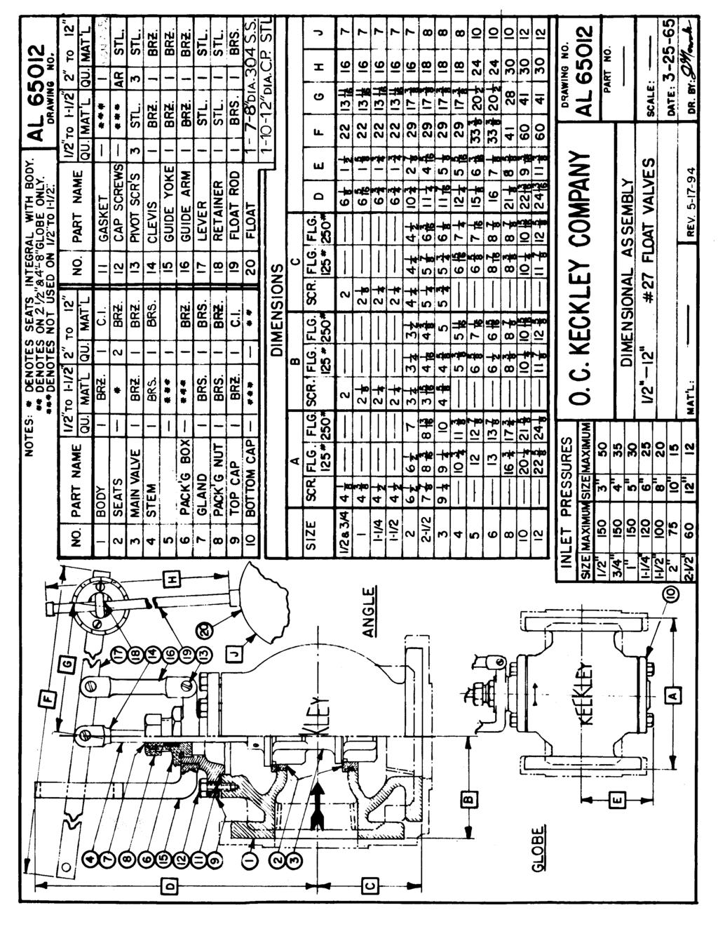
5 INSTALLATION, OPERATING AND MAINTENANCE INSTRUCTIONS TYPE NO. 27 FLOAT VALVE & NO. 62 LEVER VALVE APPLICATION/SERVICE: The NO. 27 and NO. 62 double seated valves are recommended for continuous service applications where a tight closing is not essential. The NO. 27 is most commonly used to maintain a water level in a tank by means of the attached float linkage. The NO.62 lever valve is designed to control the flow of liquid by an external power source. By reversing the linkage, both the NO. 27 and NO. 62 may be set to either open or close on level rise. MAXIMUM PRESSURE & TEMPERATURE LIMITS Pipe Size Pressure Pipe Size Pressure 1 / 2 " to 1" 150 # /in 2 4" 35 # /in / 4 " 120 # /in 2 5" 30 # /in / 2 " 100 # /in 2 6" 25 # /in 2 2" 75 # /in 2 8" 20 # /in / 2 " 60 # /in 2 10" 15 # /in 2 3" 50 # /in 2 12" 12 # /in 2 Maximum Temperature is 406 o F for all sizes CONSTRUCTION FEATURES: In sizes 1½ and smaller these valves have bronze bodies with integral seats are available with threaded ends only. In sizes 2 and larger, the standard bodies are cast iron with removable bronze seats. Threaded connections are available in sizes up to 3 and flanged connections are available in sizes 2 and larger. Other materials are available (consult factory). All sizes of these valves are available in either a Globe (straight through) or Angle (side inlet-bottom discharge) configuration. INSTALLATION: Thoroughly clean dirt, slag, etc. from both the valve body and inlet pipe. Install the NO. 27 float valve near the water level you wish to maintain with the valve stem in a vertical position; rotate the swivel guide yoke so that the float rests in calm water. Turbulence in the tank should be avoided, as it will proportionally decrease the working life of any moving parts. If turbulence exists, it may be necessary to extend the piping down from the water maintained. Stilling wells may also be used to dampen the effects of turbulence on the float. Install the NO. 62 lever valve wherever desired and arrange it to be operated by the NO. 20 float box, NO. 20M float mechanism, by hand or by another suitable means. It is recommended that you install both a strainer and a shutoff valve on the inlet side of these valves. The strainer will keep debris from clogging these valves and the shutoff valve will allow for easy access to the valve should it need to be removed. The direction of flow through these valves should agree with the markings on the side of the valve body. These valves should be protected from freezing water both in the valve, and on the surface of the water. START UP: Open the upstream shut off valve gradually to permit the tank to fill slowly and to also allow time for the necessary adjustment of the float rod and linkage to obtain the desired maximum water level; then open the shut off valve completely. Precisely adjust the water level by changing the floats position. TROUBLES AND REMEDIES: Problem: Valve leaks more than allowable. Solution: 1. Check the inlet pressure gauge. Do not exceed the maximum allowable inlet pressure shown. 2. Disassemble valve and clean the seating surfaces. Check for wear and replace components as needed. Problem: Valve sticks or leaks at stem. Solution: Stem packing may be too tight. Repack and tighten the gland only finger tight. Problem: Valve closes suddenly or chatters. Solution: 1. Check the size of the valve against the capacity (GPM) needed. Do not use an oversized valve. It is recommended that a valve have between 50% to 100% more capacity than the normal demand. 2. Weighting the float may slow the action. MAINTENANCE: The operation and condition of the valve should be discharge side to a point well below the lowest level of checked at regular intervals. O.C. Keckley Company 3400 Cleveland Street P.O. Box 67 Skokie, IL Phone FAX
6
Type S301 & S302 Gas Regulators INTRODUCTION INSTALLATION. Scope of Manual. Description. Specifications. Type S301 and S302. Instruction Manual
 Fisher Controls Instruction Manual Type S301 & S302 Gas Regulators October 1981 Form 5180 WARNING Fisher regulators must be installed, operated, and maintained in accordance with federal, state, and local
CAST IRON VALVES FLOAT VALVE
 CAST IRON VALVES FLOAT VALVE NETAFIM CAST IRON VALVES FLOAT VALVE INLINE 25-400MM ANGLE 50-100MM SPECIFICATIONS Manufactured to ISO 9001 Available Valve sizes INLINE Flanged 50mm to 600mm & Threaded 19mm
Cash Valve TYPE KP PILOT OPERATED BACK PRESSURE VALVE. ISSUED - DECEMBER 2000 CAVMC-0518-US-0208 ISO 9001 Certified
 Cash Valve PILOT OPERATED BACK PRESSURE VALVE ISSUED - DECEMBER 2000 CAVMC-0518-US-0208 ISO 01 Certified KP HIGH CAPACITY PILOT OPERATED BACK PRESSURE VALVE DESCRIPTION The Cash Valve Type KP is a pilot
CASH VALVE TYPE KP BACK PRESSURE VALVES
 A high capacity pilot operated back pressure valve that offers accurate control and dependable protection against overpressure conditions FEATURES Automatically maintains maximum pressure in a vessel or
MEGR-1627 Instruction Manual
 MEGR-1627 HIGH FLOW GAS REGULATOR Instruction Manual- Look Inside For: Description Installation Remote Vent Line Installations Startup and Adjustment Shutdown Maintenance Body Maintenance Procedures Diaphragm
Cash Valve TYPE G-4 PILOT OPERATED PRESSURE REDUCING REGULATOR FOR STEAM, AIR AND GASES. ISSUED - MARCH 2001 CAVMC-0512-US-0208 ISO 9001 Certified
 Cash Valve TYPE G-4 PILOT OPERATED PRESSURE REDUCING REGULATOR FOR STEAM, AIR AND GASES ISSUED - MARCH 2001 CAVMC-0512-US-0208 ISO 9001 Certified TYPE G-4 DESCRIPTION FIG 2042 - Bronze FIG 2043 - Bronze
Operation & Maintenance Manual Place this manual with valve or person responsible for maintenance of the valve
 Operation & Maintenance Manual Place this manual with valve or person responsible for maintenance of the valve Model CYCLE GARD II, CI & CNA YOUR PRODUCT INFORMATION: Model Number: Date: Serial Number:
SUBMITTAL NOTES PROJECT: Ross Model 50RWR-A Pilot Operated Surge Relief Valve with Hydraulic Anticipation. Size: inch / mm
 SUBMITTAL NOTES PROJECT: Ross Model 50RWR-A Pilot Operated Surge Relief Valve with Hydraulic Anticipation Size: inch / mm Every Ross Valve shall be hydrostatically tested for body integrity and tight seating
V43 Pressure Actuated Water Regulating Valve
 FANs 125, 121 Product/Technical Bulletin V43 Issue Date 0996 V43 Pressure Actuated Water Regulating Valve The V43 Pressure Actuated Water Regulating Valves are designed to regulate water flow for water-cooled
Standard Operating and Maintenance Instructions for Pumping System Model PS-90
 Standard Operating and Maintenance Instructions for Pumping System Model PS-90 High Pressure Equipment Company 2955 West 17th Street, Suite 6 PO Box 8248 Erie, PA 16505 USA 814-838-2028 (phone) 814-838-6075
Installation Operation Maintenance. Bermad Level Control Valve with Modulating Horizontal Float Pilot valve One Way Flow IOM.
 Bermad Level Control Valve with Modulating Horizontal Float Pilot valve One Way Flow Model: FP 450-80 Installation Operation Maintenance PAGE 1 OF 5 1. Safety First BERMAD believes that the safety of personnel
627 Series Pressure Reducing Regulators
 627 Series Pressure Reducing Regulators Introduction The 627 Series direct-operated pressure reducing regulators (Figure 1) are for low and high-pressure systems. These regulators can be used with natural
Types PT and ETP Dome-Loaded Pressure Regulator Valves
 1BInstallation, Operation, and Maintenance Manual Types PT and ETP Dome-Loaded Pressure Regulator Valves 58 0BINSTRUCTIONS FOR TYPE PT REGULATORS 2BCAUTIONARY NOTE It is important that the correct start-up
Cash Valve. Type G-4. Pilot Operated Pressure Reducing Regulator for Steam, Air and Gases. Flow Control
 Cash Valve Type G-4 Pilot Operated Pressure Reducing Regulator for Steam, Air and Gases Issued - March 2001 CAVMC-0512-US-0609 ISO 9001 Certified Flow Control Description FIG 2042 - Bronze FIG 2043 - Bronze
Model: 720-UL INSTALLATION OPERATION MAINTENANCE. Bermad Pressure Reducing Valve IOM. Model: FP -720-UL Sizes: 2"-12" BERMAD. Application Engineering
 Bermad Pressure Reducing Valve Model: 720-UL INSTALLATION OPERATION MAINTENANCE Application Engineering BERMAD 1. Safety First BERMAD believes that the safety of personnel working with and around our equipment
Type HSR Pressure Reducing Regulator for Residential, Commercial, or Industrial Applications
 Instruction Manual Form 5753 Type HSR October 2003 Type HSR Pressure Reducing Regulator for Residential, Commercial, or Industrial Applications W8648 Figure 1. Type HSR Pressure Regulator Introduction
Regulator from 1800 B series
 Regulator from 1800 B series Regulator from 1800 B series Measuring of industrial gases frequently requests a precise pressure regulation for the purpose of dosage and proccesing. UNIS FAGAS has two kinds
KECKLEY. Installation, Operation, and Maintenance Manual. Style KGV - Knife Gate Valve
 KECKLEY Installation, Operation, and Maintenance Manual Style KGV - Knife Gate Valve Table of Contents Introduction and Safety... 3 Safety message levels... 3 User health and safety... 3-4 Transportation
BUTTERFLY VALVES Series 800
 BUTTERFLY VALVES Series 800 WARNING Before proceeding read ALL instructions and become familiar with the equipment and associated drawings. Follow ALL applicable safety regulations and codes for pressurized
VB-7213 Series. Application. Features. Applicable Literature. 1/2" to 2" Screwed NPT Stem Up Open, Two-Way Valves General Instructions
 VB-7213 Series 1/2" to 2" Screwed NPT Stem Up Open, Two-Way Valves General Instructions Application VB-7213 series single seat, stem up open, two-way valves control water from 20 to 281 F (-7 to 138 C)
RHPS Series RD(H)F40 User Manual. Read the complete manual before installing and using the regulator.
F40 User Manual. Read the complete manual before installing and using the regulator.") RHPS Series RD(H)F40 User Manual Read the complete manual before installing and using the regulator. 2 WARNING Before removing a regulator from the system for service, you must depressurize system purge
RHPS Series RD(H)F40 User Manual Read the complete manual before installing and using the regulator. 2 WARNING Before removing a regulator from the system for service, you must depressurize system purge
CFC2. Float Control For Closed Tanks MODEL. Specifications. Dimensions (In Inches) Reservoir Connection 1" NPT (Typ. Both Ends 2 Places)
 Reservoir Connection 1 NPT (Typ. Both Ends 2 Places)") MODEL Float Control For Closed Tanks Accurate Liquid Level Control Fully Hydraulic Operation Simple Design, Easy Maintenance No Lubrication Necessary No Gears, No Mechanical Linkage Between Valve and Control
MODEL Float Control For Closed Tanks Accurate Liquid Level Control Fully Hydraulic Operation Simple Design, Easy Maintenance No Lubrication Necessary No Gears, No Mechanical Linkage Between Valve and Control
553 Series.
 38467.03 www.caleffi.com Pre-adjustable filling units Copyright 01 Caleffi 3 Series Function The automatic filling valve is a device consisting of a pressure reducing valve with compensating seat, visual
2.0 INSTALLATION & SERVICE
 Installation, Operation, and Maintenance Instructions MODEL 5600 / 5600R January 2005 CONTENTS 1.0 GENERAL 1.1 5600 Model Number Information -----------------------------------------------------------------------
D05 Pressure Regulating Valves
 D05 Pressure Regulating Valves FEATURES PRODUCT DATA Noncorroding unitized cartridge contains all working parts and is easily replaceable. Includes built-in strainer and thermal bypass. Balanced seat construction
Choosing the right miniature instrument and control valve is a snap
 Choosing the right miniature instrument and control valve is a snap INVALCO Micro Valve The Micro Valve is a unique miniature valve offering versatility and rugged construction. Since its introduction
Model: 43T. Bermad Pressure Relief Valve
 Model: 43T Bermad Pressure Relief Valve Installation Operation Maintenance Manual () Rev.C1_01.08.17 Page 1 of 10 Safety First BERMAD believes that the safety of personnel working with and around our equipment
Wet pipe low flow foam/water system
 December 6, 2010 Foam 14a 1. The Viking Low Flow Foam/Water proportioning system, is a UL Listed and FM Approved system, for use with Viking supplied foam concentrates. This system consists of a standard
TECHNICAL INSTRUCTIONS
 TECHNICAL INSTRUCTIONS Hydroguard Series 410 Valves Model 5 and Model 8 Form TI410-5 v3 DESCRIPTION The Series 410 Hydroguard is a pressure compensating mixer which delivers a predetermined water temperature,
1200B2 Series Service Regulators. Instruction Manual
 00B Series Service Regulators Instruction Manual 00B Series Service Regulators 0 Elster American Meter 00B Series Service Regulators General Information The 00B Series Service Regulators are available
KENNEDY VALVE RESILIENT WEDGE GATE VALVE MAINTENANCE MANUAL
 KENNEDY VALVE Division of McWane, Inc. 1021 East Water Street P.O. Box 931 Elmira, New York 14902-0931 Telephone (607) 734-2211 Fax (607) 734-1003 KENNEDY VALVE RESILIENT WEDGE GATE VALVE MAINTENANCE MANUAL
Model 420-HY Pressure Regulating Hydrant Valve
 Model 420-HY Pressure Regulating Hydrant Valve INSTALLATION OPERATION MAINTENANCE 1. Safety First BERMAD believes that the safety of personnel working with and around our equipment is the most important
! WARNING. Model PFC-1-G (direct acting) PFC-1-GR (reverse acting) Modulating Pneumatic Liquid Level Controls INSTRUCTION MANUAL MM-110B
 PFC-1-GR (reverse acting) Modulating Pneumatic Liquid Level Controls INSTRUCTION MANUAL MM-110B") INSTRUCTION MANUAL MM-110B Model PFC-1-G (direct acting) PFC-1-GR (reverse acting) Modulating Pneumatic Liquid Level Controls APPLICATIONS: Use with other pneumatic devices, for liquid level sensing in
INSTRUCTION MANUAL MM-110B Model PFC-1-G (direct acting) PFC-1-GR (reverse acting) Modulating Pneumatic Liquid Level Controls APPLICATIONS: Use with other pneumatic devices, for liquid level sensing in
TECHNICAL DATA. Page 1 of 12
 Page 1 of 12 1. DESCRIPTION The Viking Regulating Valve is a direct-acting, single-seated, spring-loaded diaphragm valve. When installed as a pilot regulating valve on a Viking Model H or J Flow Control
VB-7211 Series. Application. Features. Applicable Literature. 1/2" to 1-1/4" Union End NPT Stem Up Open, Two-Way Valves General Instructions
 TAC 1354 Clifford Avenue P. O. Box 2940 Loves Park, IL 61132-2940 www.tac.com VB-7211 Series 1/2" to 1-1/4" Union End NPT Stem Up Open, Two-Way Valves General Instructions Application VB-7211 series stem
D05T Compact Design Pressure Regulating Valves
 D05T Compact Design Pressure Regulating Valves FEATURES PRODUCT DATA Non-corroding unitized cartridge contains all working parts and is easily replaceable. Includes built-in strainer and thermal bypass.
ROTATING DISK VALVES INSTALLATION AND MAINTENANCE 1. SCOPE 3 2. INFORMATION ON USAGE 3 3. VALVE TYPES 3 4. OPERATORS 5 5. VALVE CONSTRUCTION 6
 Sub Section INDEX Page Number 1. SCOPE 3 2. INFORMATION ON USAGE 3 3. VALVE TYPES 3 4. OPERATORS 5 5. VALVE CONSTRUCTION 6 6. INSTALLATION AND OPERATION 6 7. MAINTENANCE 8 8. REPAIR 9 9. ASSEMBLY 10 10.
1805 Series Relief Valves
 Instruction Manual Form 1211 1805 Series October 2011 1805 Series Relief Valves! WARNING Failure to follow these instructions or to properly install and maintain this equipment could result in an explosion
PENBERTHY SUBMERSIBLE AUTOMATIC SUMP DRAINER INSTALLATION, OPERATION AND MAINTENANCE INSTRUCTIONS
 Before installation, these instructions must be read carefully and understood. PRODUCT WARRANTY Emerson warrants its Penberthy products as designed and manufactured to be free of defects in the material
Eaton Filtration, LLC
 Eaton Filtration, LLC 900 Fairmount Avenue, Elizabeth, NJ 07207 Phone: 908-787-1000 Fax: 908-351-7893 E-Mail: filtration@eaton.com Web: www.filtration.eaton.com Installation, Operation & Service Manual
TECHNICAL DATA. the Viking Pilot Pressure Regulating Valve 1 Model A-1 Speed Control Assembly: OBSOLETE. the Viking Speed Control Assembly 1
 November 30, 1994 534 a 1. PRODUCT NAME VIKING 2" (50mm), 3" (75mm), 4" (100mm), 6" (150mm) 2. MANUFACTURER THE VIKING CORPORATION 210 N. Industrial Park Road Hastings, Michigan 49058 U.S.A. Telephone:
BERMAD Waterworks. Level Control Valve with Altitude Pilot. 700 Series. Model X. Features and Benefits. Major Additional Features
 Level Control Valve with Altitude Pilot High level reservoirs & water towers Energy cost critical systems Systems with poor water quality Inherent refreshing Level sustaining at reservoir outlet The Level
The Shand & Jurs Model Vapor Guard Tank Blanketing Valve
 Lower maintenance due to fewer parts Occupies less space, less stress to tank Teflon is inert to most chemicals; extends service life Simplifies and lowers maintenance cost Optimizes flow of blanketing
End Connection. Thread x Thread N/A N/A N/A N/A Flange x Flange N/A
 Worldwide Contacts www.tyco-fire.com Model RV-1 Pressure Relief Valve, Pilot-Operated, Globe and Angle Body Styles General Description Valves, through inch (DN50 through DN00), are factory assembled and
Types S108K and S109K Pressure Reducing Regulators with Integral Slam-Shut Device
 Instruction Manual Form 5492 Types S108K and S109K May 1999 Types S108K and S109K Pressure Reducing Regulators with Integral Slam-Shut Device Introduction Fisher regulators must be installed, operated
Temperature Controllers
 IM0004 April 2013 CONTENTS T-12 Thermostat PAGE Introduction 1 Scope 1 Description 1 Specification 1 Temperature Controllers 2 INTRODUCTION CAUTION Prior to installing, the instructions provided herein
TECHNICAL DATA. than the water inlet pressure to the concentrate
 Foam102a 1. DESCRIPTION The Viking Low Flow Foam/Water proportioning system, is a UL Listed and FM Approved system, for use with 3M foam concentrates. This system consists of a standard wet pipe sprinkler
VERTICAL BLADDER TANK
 Balanced Pressure Proportioning System Reliable Foam System Requiring Only Water Power Perfect For Tight Spaces UL Listed, ASME, National Board Registered Bladder-UL162 Approved, High Tensile Pressure
TECHNICAL DATA. Pressure Regulation 531a. April 24, 2009
 April 24, 29 Pressure Regulation 531a 1. DESCRIPTION The Viking Regulating Valve is a direct-acting, single-seated, spring-loaded diaphragm valve. When installed as a pilot regulating valve on a Viking
Waterous Relief Valve
 Operating Instructions 1. Reduce pump discharge pressure with engine throttle. Make sure four way (On/Off) valve is OFF. 2. Open at least one discharge valve. Accelerate engine until pressure gage indicates
Pressure Reducing Control Valve w/ Hydraulic Check Feature
 PERTIN INSTRUTINS peration The BEE Model PR- Pressure Reducing ontrol alve with Hydraulic heck eature is a pilot controlled diaphragm valve designed to reduce a fluctuating higher upstream pressure to
TECHNICAL DATA CAUTION
 Page 1 of 12 1. DESCRIPTION The Viking Model C-2 Pilot Pressure Regulating Valve is a direct-acting, single-seated, spring-loaded diaphragm valve. When installed as a pilot regulating valve on a Viking
Types S100K and S102K Pressure Regulators
 Instruction Manual Form 5624 Types S0K and S2K 01/01 Types S0K and S2K Pressure Regulators W7478-1 Figure 1. Types S0K and S2K Pressure Regulator Introduction Scope of Manual This manual provides instructions
SABERINDO PACIF SABERINDO PACIFIC CIFIC SABERINDO PA. A Tyco International Company
 CIF A Tyco International Company 1 Foam Concentrate CIF 3% AFFF -UL Listed -UL Canada Listed 6% AFFF 6 parts AFFF concentrate to 94 parts water -UL Listed- Foam Liquid -UL Canada Listed 3% FLUOROPROTEIN
INSTALLATION, OPERATION & MAINTENANCE MANUAL
 INSTALLATION, OPERATION & MAINTENANCE MANUAL AWWA C500 SOLID WEDGE GATE VALVE 2 72 NRS and OS&Y Series 100 and Series 105 TABLE OF CONTENTS SECTION PAGE # Equipment List 2 General 3 Receipt and Inspection
Float Operated Level Controllers
 CONTENTS Float Operated Level Controllers IM0015 Nov. 2014 PAGE Introduction 1 Scope 1 Description 1 Specification 1 Control Installation 2 INTRODUCTION Side Mount Back Mount Prior to installing, the instructions
AYLESBURY 'KB' TYPE FLOAT VALVES
 PRE-INSTALLATION CHECKS AYLESBURY Valves are unlike any other float operated valve, ballcock or ball valve. Please read these instructions and refer to attached drawings before installation. Installation
Operation Manual. Diaphragm Sensed Gas Pressure Regulators
 687 Technology Way Napa, CA 94558 Phone: (707) 259-0102 FAX: (707) 259-0117 www.aptech-online.com Diaphragm Sensed Gas (AP/AZ/AK Models: 20, 100, 500, 1000, 1000T 10PA, 1100, 1200, 12PA, 1300, 1400T, 14PA,
VB-7263 Series. Application. Features. Applicable Literature
 TAC 1354 Clifford Avenue P. O. Box 2940 Loves Park, IL 61132-2940 www.tac.com VB-7263 Series 1/2" to 2" Screwed NPT Stainless Steel Trim with Teflon Disc Stem Up Closed, Two-Way Valves General Instructions
299H Series. Introduction. P.E.D. Categories. Specifications. Installation. Warning. Installation Guide English September 2012
 Installation Guide English September 2012 299H Series Introduction This Installation Guide provides instructions for installation, startup, and adjustment of 299H Series regulators. To receive a copy of
Differential Pressure Regulator Type Type 45-6 (0.1 to 1 bar, DN 15) Mounting and Operating Instructions EB 3226 EN
 Mounting and Operating Instructions EB 3226 EN") Differential Pressure Regulator Type 45-6 Type 45-6 (0.1 to 1 bar, DN 15) Mounting and Operating Instructions EB 3226 EN Edition March 2008 Contents Contents Page 1 Design and principle of operation...................
Differential Pressure Regulator Type 45-6 Type 45-6 (0.1 to 1 bar, DN 15) Mounting and Operating Instructions EB 3226 EN Edition March 2008 Contents Contents Page 1 Design and principle of operation...................
Pipe Thread Connection 1/2 inch NPT. Friction Loss Refer to Figure 3
 Worldwide Contacts www.tyco-fire.com Model B-1 Pipe Line Strainer General Description The Model B-1 Pipe Line Strainers (Ref. Figures 1 and 2) are designed for installation in the water supply connection
Full Range Pressure Compensating Variable Flow Control
 Engineering & Manufacturing Solutions Specifications: See flow chart for capacity. Rated for 3000 psi (207 bar). Weighs 7- ¾ lbs. (3.52 kg). 30-Micron Filtration Recommended. Torque to turn side lever
1800C and 1800C-HC Series Service Regulators
 1800C and 1800C-HC Series Service Regulators Installation Instructions www.elster-americanmeter.com General Information: The 1800C and 1800C-HC Regulators are available as Full Capacity Internal Relief
APCO ARV CLEAN WATER AIR RELEASE VALVES. Model 50A
 APCO ARV CLEAN WATER AIR RELEASE VALVES Model 50A Instruction D12013 February 2017 Instructions These instructions provide installation, operation and maintenance information for APCO ARV Clean Water Air
C 10 Pressure Reducing Valve
 C 10 Pressure Reducing Valve C 10 Direct Acting Pressure Reducing Valve The C10 balanced pressure reducing valve range is designed for use on water/air (gas) applications and for installations which have
Reduce pressure zone device suitable for high and medium hazard rated applications Flanged end connections
 VALVCHEQ Backflow Preventers Reduce pressure zone device suitable for high and medium hazard rated applications Flanged end connections Features General application The RP03 provides protection from both
TECHNICAL DATA. Low-Flow Foam Preaction System with Hydraulically Actuated Concentrate Control Valve.
 Foam 302 a 1. DESCRIPTION (Refer to Figure 1 on page 302 e.) The Viking Low-Flow Foam/Water Proportioning System is a UL Listed and FM Approved system, for use with 3M and Viking brand foam concentrate.
TECHNICAL DATA Q= C. Table 1 - Specifications
 September 25, 2013 Pressure Regulation 537a 1. Description The Model B-3 Pilot Operated Pressure Control Valve is a factory assembled unit. The unit consists of a Model J-2 Halar coated Flow Control Valve,
Operating Instructions Model and Hydrostatic Test Pump
 Operating Instructions Model 39300 and 39301 Hydrostatic Test Pump Dimension Weight Pump Style Capacity Pressure Motor Lubrication Control Gauge Inlet Connection Outlet Connection Discharge Hose Hose Ends
Speed control assembly model A-1
 Pressure Regulation 533a 1. DESCRIPTION The Viking Speed Control Assembly provides adjustment of the opening speed of Viking Deluge Valves, and adjustment of both the opening and closing speed of Viking
HORIZONTAL BLADDER TANK
 Balanced Pressure Proportioning System Reliable Foam System Requiring Only Water Power Perfect For Low Ceilings UL Listed, ASME, National Board Registered Bladder-UL162 Approved, High Tensile Pressure
Bermad Pressure Reducing. Model: 42T
 Bermad Pressure Reducing Pilot Operated Pressure Control Valve Model: 42T Installation Operation Maintenance Manual (IOM) REV. 27.7.17 Page 1 of 12 Safety First BERMAD believes that the safety of personnel
VB-7212 Series. Application. Features. Applicable Literature. 5/8" O.D., 45 SAE Flared Stem Up Open, Two-Way Valves General Instructions
 VB-7212 Series 5/8" O.D., 45 SAE Flared Stem Up Open, Two-Way Valves General Instructions Application VB-7212 series single seat, stem up open, two-way valves control water from 20 to 281 F (-7 to 138
Model 1800 PFM Series Regulator. Technical Bulletin
 Model 0 PFM Series Regulator Technical Bulletin Model 0 PFM Series Regulator 0 Elster American Meter The 0 PFM Series regulators are designed to control natural gas, air, nitrogen, carbon dioxide, propane
Eaton Filtration, LLC
 Eaton Filtration, LLC 900 Fairmount Avenue, Elizabeth, NJ 07207 Phone: 908-787-1000 Fax: 908-351-7893 E-Mail: filtration@eaton.com Web: www.filtration.eaton.com Installation, Operation & Service Manual
IMPORTANT SAFETY INSTRUCTIONS READ AND FOLLOW ALL INSTRUCTIONS SAVE THESE INSTRUCTIONS
 Warrior D.E. Filter Operating Procedures IMPORTANT SAFETY INSTRUCTIONS READ AND FOLLOW ALL INSTRUCTIONS SAVE THESE INSTRUCTIONS Table of Contents SECTION I. FILTER INSTALLATION... 1 SECTION II. FILTER
KENNEDY VALVE OPERATION & MAINTENANCE MANUAL
 2 54 ROTATING DISC GATE VALVE OPERATION & MAINTENANCE MANUAL Rel. 5/27/16 1 TABLE OF CONTENTS 3 General 3 Receipt & Inspection 4 Gate Valve Storage & Handling 5 6 Installation 7 Operation 8 Field Testing
WW-730. Pressure Sustaining/Relief Control Valve
 WW-730 Pressure Sustaining/Relief Control Valve Installation Operation & Maintenance Page 1 of 6 1. DESCRIPTION The Model 730 Pressure Relief / Sustaining Valve is an automatic control valve designed to
Models 461-S, 461-8S and S Regulators. R-1330 Rev. 7
 Models 461-S, 461-8S and 461-12S Regulators R-1330 Rev. 7 461-S, 461-8S and 461-12S Regulators The Sensus Models 461-S, 461-8S and 461-12S are balanced valve, spring type regulators designed for distribution
VB-7323 Series. Application. Features. Applicable Literature. 1/2 to 2 Screwed NPT Three-Way Diverting Valves General Instructions
 VB-7323 Series 1/2 to 2 Screwed NPT Three-Way Diverting Valves General Instructions Application VB-7323 series three-way diverting valves control hot or chilled water in heating or air conditioning systems.
SINGER MODEL 106/206-RPS-L&H
 DESCRIPTION: Model 106/206-RPS-L&H dissipates surges caused by power failure to pumps. The valve anticipates the surge by opening on low line pressure associated with sudden stopping of pumps. This assures
TITAN FLOW CONTROL, INC.
 PREFACE: This manual contains information concerning the installation, operation, and maintenance of Titan Flow Control (Titan FCI) Simplex Basket Strainers. To ensure efficient and safe operation of Titan
FM Approved - Automatic Water Control Valve as standard deluge valve. No formal approval available for coating. Foam Concentrate
 December 6, 2010 Foam 21a 1. Description With Multiple Foam/Water Deluge Systems Supplied by a Bladder Tank, multiple deluge foam risers can be supplied from a single foam concentrate source. Where a bladder
Types 95L and 95H Pressure Regulators
 Instruction Manual Form 1151 Types 95L and 95H July 1990 Types 95L and 95H Pressure Regulators W1888 W1888 W5652 Figure 1. NPT Body (Left), NPT Body (Middle), and Flanged Body (Right) Pressure Regulators
OPERATING AND MAINTENANCE MANUAL
 Series 4300 Engineered Performance TABLE OF CONTENTS 0 INTRODUCTION 1 1 Scope 1 2 Description 1 3 Specifications 1 0 INSTALLATION 1 1 Mounting 1 2 Piping 1 1 Connecting Process Pressure 2 2 Vent Connections
INDUSTRIAL VALVES MODELS: C62-A; C62-D. INSTRUCTION MANUAL Installation Operation Parts Service DIAPHRAGM BYPASS PRESSURE REGULATING VALVES
 INSTRUCTION MANUAL Installation Operation Parts Service IMPORTANT Record your Regulator model number and serial number here for easy reference: Model No. Serial No. Date of Purchase When ordering parts
Type FEQ Slam-Shut Valve
 Instruction Manual Form 5865 Type FEQ December 2012 Type FEQ Slam-Shut Valve Contents Introduction...1 Principle of Operation...1 Specifications...2 Installation...2 Commissioning...7 Adjustment...9 Shutdown...10
Hydraulic Punch Drivers
 SERVICE MANUAL 7804SB / 7806SB Quick Draw 7704SB / 7706SB Quick Draw Flex Quick Draw Hydraulic Punch Drivers Serial Codes AHJ and YZ Read and understand all of the instructions and safety information in
Mounting and operating instructions EB 2530 EN. Self-operated Pressure Regulator. Pressure Reducing Valve Type M 44-2
 Self-operated Pressure Regulator Pressure Reducing Valve Type M 44-2 Type M 44-2, connection G 1 4, K VS = 0.15 Type M 44-2, connection G 1, K VS = 6 Fig. 1 Type M 44-2 Pressure Reducing Valve Mounting
WaterSource Heat Pump Hose Kit Performance Specification-Summary
 WaterSource Heat Pump Hose Kit Performance Specification-Summary AUTOMATIC & MANUAL BALANCING HOSE KITS Contractor shall provide and install Hays Hose Kits. Each kit, shall include a Hays 2500 Series Mesurflo
VALVCHEQ BACKFLOW PREVENTERS FIGURE RP03
 Reduce pressure zone device suitable for high and medium hazard rated applications Flanged end connections FEATURES GENERAL APPLICATION The RP03 provides protection from both backsiphonage and backpressure
300 Series. Automatic Hydraulic Control Valves
 Automatic Hydraulic Control Valves AVFI Pty Ltd 54 Enterprise Drive Bundoora Vic 3083 p: 03 8467 0000 f: 03 8467 0099 e: avfi@avfi.com.au w: www.avfi.com.au 300 Series General 300 SERIES Automatic Hydraulic
64 Series Pressure Reducing Regulators
 Instruction Manual Form 1245 64 Series March 2006 64 Series Pressure Reducing Regulators W1943 Figure 1. 64 Series Regulator Introduction Scope of Manual This manual provides instructions for the installation,
COMBINATION AIR RELEASE DEGASSING (CARD) VALVES INSTALLATION AND MAINTENANCE MANUAL
 VALVES INSTALLATION AND MAINTENANCE MANUAL") COMBINATION AIR RELEASE DEGASSING (CARD) VALVES INSTALLATION AND MAINTENANCE MANUAL SPECIFICATIONS: The CARD series air valves are available in 3 pipe sizes, 1, 2 and 4 NPT or socket. Maximum inlet pressure
COMBINATION AIR RELEASE DEGASSING (CARD) VALVES INSTALLATION AND MAINTENANCE MANUAL SPECIFICATIONS: The CARD series air valves are available in 3 pipe sizes, 1, 2 and 4 NPT or socket. Maximum inlet pressure
Model 141-A Regulators
 Regulator Installation and Maintenance Instructions Model -A Regulators RM- Rev. Introduction The Model -A regulator is both easy to use and durable for high pressure jobs. Thus, these field regulators
CLASS TLP Pressure Reducing Valve
 CLASS TLP Pressure Reducing Valve CLASS TLP Direct Acting Pressure Reducing Valve The Class TLP balanced direct acting pressure regulator is designed for use on installations that have varying inlet pressures
FILTER BYPASS CONTROL
 Differential Control Valve Series 110 The Series 110 Differential Control Valve is designed to accurately control the pressure difference between any two points. In some systems this means the valve remains
BACK PRESSURE / SUSTAINING
 In many liquid piping systems, it is vital that line pressure is maintained within relatively narrow limits. This is the function of the 108 Pressure Relief / Back Pressure Series of the OCV control valves.
TITAN FLOW CONTROL, INC.
 PREFACE: This manual contains information concerning the installation, operation, and maintenance of Titan Flow Control (Titan FCI) WYE Type Strainers. To ensure efficient and safe operation of Titan FCI