SpiroGuide II BASIC MODEL
|
|
|
- Angelina Norton
- 5 years ago
- Views:
Transcription
1 31268D01 SpiroGuide II BASIC MODEL USER MANUAL Breathing Apparatus with Digital Display Wireless Heads-Up Display USER MANUAL SAFETY NOTICE CYLINDER MOUNTING CONNECTING / DISCONNECTING HUD ADJUSTING SIZE DONNING START-UP TEST DURING USE CYLINDER PRESSURE WARNINGS AUTOMATIC DISTRESS SIGNAL UNIT(ADSU)- (OPTIONAL) REMOVING THE APPARATUS CLEANING AND DISINFECTING SERVICE AND TESTING BATTERIES STORAGE EXTRA AIR CONNECTION USAGE WITH AIRLINE SYSTEM MARKINGS...23


2

3 B A 12


4 :a 2 x 16:b
5 SpiroGuide II BASIC MODEL USER MANUAL Breathing Apparatus with Digital Display Wireless Heads-Up Display The equipment is type tested by DEKRA EXAM GmbH, Dinnendahlstr. 9; Bochum, Germany. EC type examined (Directive 89/686/EEC) by DEKRA EXAM GmbH, Dinnendahlstr. 9; Bochum, Germany. SpiroGuide II consists of: Breathing Apparatus Computer (BAC) Digital Display located at the pressure gauge QS II Breathing Apparatus Optional Heads-Up Display (HUD) located inside the face mask Optional fully integrated Automatic Distress Signal Unit (ADSU) / Personal Alert Safety System (PASS) 1 SAFETY NOTICE The product must only be used with Interspiro cylinders: Spirolite 3.4L, 6.7L, cylinder pack or Aluminum line 6.8L or 9.0L Steel 4L or 6L. ATTENTION! BREATHING APPARATUS WITH TWIN CYLINDER AND CYLINDER PACK CONFIGURATIONS: SPIROLITE 6,7L OR 326,7, COMPOSITE WITH ALUMINUM LINER 6,8L OR 9,0L AND STEEL CYLINDERS 4L OR 6L, EXCEEDS THE TOTAL WEIGHT LIMIT ACCORDING TO 6.6 IN EN 137:2006. The product must only be used by personnel in good health and trained in the use of respiratory protective equipment. Individuals with beards or large sideburns may not obtain an adequate seal. The apparatus must be maintained, serviced and tested as described in this user manual, Interspiro service manuals and Interspiro test instructions. INTERSPIRO IS NOT RESPONSIBLE FOR COMBINATIONS OF PRODUCTS, UNLESS PUT TO MARKET BY INTERSPIRO CHANGES OR ADAPTATIONS MADE TO THE PRODUCT BY A THIRD PARTY 5
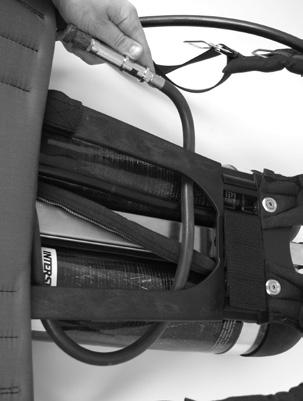
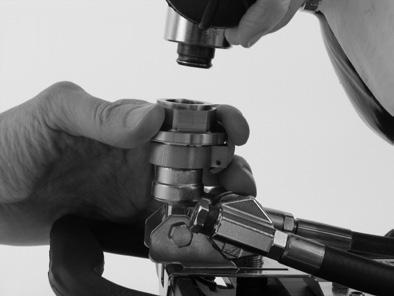
6 Changes to this document - necessitated by typographical errors, inaccuracies of current information or improvements and changes of equipment - may be made at any time without prior notice. Always refer to for product updates, document updates and service bulletins. Exposure to extreme conditions, may require different procedures rather than those described in this manual. The guarantees and warranties specified in the conditions of sale are not extended by this Safety Notice. The breathing air with which the cylinders are charged must meet the requirements according to EN 12021, being free from oil, toxic substances and having low humidity. The duration of a compressed air breathing apparatus depends on the volume of air in the compressed air cylinder(s) and the air consumption, which is specific to the wearer and is affected by the work load. When taking air from the extra air connection, which some models are equipped with, the air consumption increases and the duration of the apparatus decreases. When operating with two separate independently-valved cylinders, both cylinders must be charged with similar working pressures. Always open both cylinder valves when pressurizing the breathing apparatus and ensure that both cylinder valves are kept open during the use of the apparatus. If fitted with a mechanical warning whistle, that warning will be activated at a slightly different pressure than the low air warning triggered by the BAC. For safety reasons, the first warning activated should be heeded If the self contained breathing apparatus is to be used in conjunction with other personal protective equipment it is important to ensure that the additional personal protective equipment is compatible with the breathing apparatus and does not impair the full protection of the respiratory protective device. Examples of dangers which may require the use of additional personal protective equipment: -Liquids, steam or gases which can damage the skin. -Pollutants absorptive by skin -Thermal radiation -Mechanical effects -Explosive environments -Oxygen-enriched breathing air. 2 CYLINDER MOUNTING SINGLE CYLINDER 1. Check that the cylinder strap buckle is positioned with the buckle as close to the backplate as possible. Place the cylinder on the backplate. [Fig. 1] 2. Check the connection O-ring and screw the cylinder valve hand tight to the cylinder connection of the manifold block. [Fig. 1] NOTE! FOR CYLINDER QUICK COUPLING SEE PAGE 8. 6
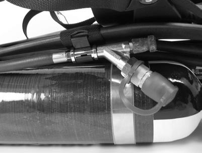
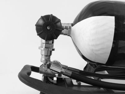
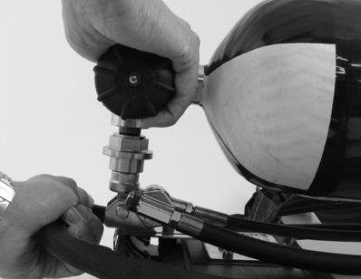
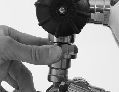
7 3. Fasten cylinder strap buckle around the cylinder and hook together with the buckle. Adjust the length of the strap if needed. Do not over tighten. If the strap is over tightened the buckle and backplate will be damaged. 4. Close the lever on the buckle. Make sure that the locking tab has locked the lever in the closed position. (To release the cylinder buckle the locking tab must be pressed down.) [Fig. 2] TWIN CYLINDERS ATTENTION! WHEN OPERATING WITH TWO SEPARATE INDEPENDENTLY-VALVED CYLINDERS, BOTH CYLINDERS MUST BE CHARGED WITH SIMILAR WORKING PRESSURES. ALWAYS OPEN BOTH CYLINDER VALVES WHEN PRESSURIZING THE BREATHING APPARATUS AND ENSURE THAT BOTH CYLINDER VALVES ARE KEPT OPEN DURING THE USE OF THE APPARATUS. 1. If previously used for single cylinder start by disengaging the cylinder strap from the four lugs on the backplate. [Fig. 3] 2. Check that the cylinder strap is positioned with the buckle as close to the backplate as possible. 3. If applicable, mount the strap holder and the cylinder distance piece. [Fig. 4] 4. Check the connection O-ring and screw the T-piece to the cylinder connection of the manifold block - Do not tighten. [Fig. 5] 5. Place the cylinders on the backplate with the strap holder between the cylinders. Check that the hoses are positioned between the cylinders and not squeezed between the cylinders and backplate. [Fig. 6] 6. Check the connection O-rings and screw the cylinder valves hand tight to the cylinder connections of the T-piece. 7. Tighten the T-piece to the manifold block by hand. 8. Fasten the cylinder strap buckle around the cylinders and hook together with the buckle. Adjust the length of the strap if needed. Do not over tighten. If the strap is over tightened the buckle and backplate will be damaged. 9. Close the lever of the buckle. Make sure that the locking tab has locked the lever in the closed position. (To release the cylinder buckle the locking tab must be pressed down.) [Fig. 2] CYLINDER PACK Mounting 1. Place the cylinder pack on a flat surface with the cylinder valve towards you. 2. Check the connection O-ring and screw the cylinder valve hand-tight to the cylinder connection of the manifold block. [Fig. 7] NOTE! FOR CYLINDER QUICK COUPLING SEE PAGE Fit the holes of the cylinder bracket onto the guide washers and push the backplate away from you until the harness clicks in position [Fig. 8]. Check that the cylinder pack is mounted properly by lifting the harness carefully in the upper 7
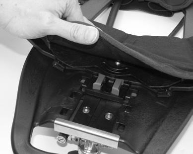
8 and lower part of the backplate. 4. If applicable mount the rescue hose and fasten the Y-connection with the rescue hose holder. [Fig. 9] Dismounting 1. Unscrew the cylinder connection of the manifold block from the cylinder valve. 2. Push the locking arm on the upper part of cylinder bracket and pull the harness towards you at the same time. Rescue hose usage To use the rescue hose, grab the Y-connection and pull the hose lose from the harness. The protective covers on the couplings must be removed before connecting the hoses. QUICK COUPLING OPTION Connection Align the adapter in the cylinder valve with the connection of the manifold block. Push down the cylinder until it clicks together with the manifold. [Fig. 10] Disconnection Push the ring of the quick coupling towards the backplate [A in Fig. 11]. Lift away the cylinder [B in Fig. 11]. 3 INSTALLING / REMOVING HUD INSTALLING THE WIRELESS HUD 1. Place one side of the HUD on an angle inside the mask and press down. 2. Make sure the right and left side of the HUD are securely seated in the rounded areas of the mask rubber, and below the two protruding lugs on the visor. REMOVING THE WIRELESS HUD 1. Lift one end of the HUD and remove it from the mask. 4 ADJUSTING SIZE NOTE! WHEN STANDING STRAIGHT WITH THE BREATHING APPARATUS DONNED THE MAJORITY OF THE WEIGHT SHALL BE CARRIED ON THE HIPS AND NOT THE SHOULDERS. To adjust the height of the hip belt, push the red buttons under the hip belt together and slide the complete hip belt up or down to the correct size. [Fig. 12] The harness can be adjusted into four different sizes. Size indications are available on both the front and backside of the harness. 8
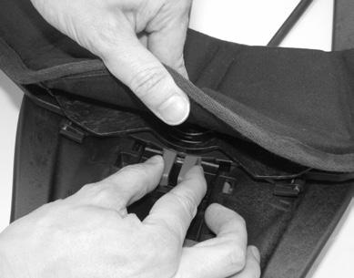
9 5 DONNING NOTE! THIS SECTION DESCRIBES HOW TO DON THE APPARATUS PERFORMING A SHORT TEST DURING THE START-UP. FURTHER INFORMATION REGARDING THE START-UP TEST AND INSTRUCTIONS FOR PERFORMING THE FULL TEST ARE GIVEN IN SECTION Connect the breathing hose to the breathing valve. [Fig. 13] 2. Connect the face mask and breathing valve according to the instructions given in the user manual for the face mask. 3. Loosen the shoulder straps and the waist belt and put on the apparatus. 4. Place the neck strap over the head. 5. Fasten the waist belt buckle and tighten, ensuring that the majority of the weight is carried on the waist and not the shoulders. [Fig. 14] 6. Adjust the shoulder straps and tuck in any loose straps. If applicable fasten the chest strap and tighten, tuck in any loose straps. [Fig. 15] 7. Switch off positive pressure. 8. Open the cylinder valve fully. The apparatus now starts to perform the start-up test. 9. Check that the HUD is fully pushed down inside the mask. 10. Don the face mask according to the instructions given in the face mask user manual. 11. Check the Digital Display and confirm TEST OK or failure indication (see section 6) by pressing the backlight button (section 7, Fig. 7-A) on the display. 6 START-UP TEST SHORT TEST AND FULL TEST When the cylinder valve is opened, an automatic start-up check is performed. Depending on user interaction, either a Short Test or a Full Test is performed. The Short Test is performed in accordance with the section Performing the Short Test and automatically performs the following tests: - Cylinder pressure above pre-set level (configuration dependent) - Battery has at least two hours of operation - Electronic systems are working When the test is complete, the test results must be confirmed by the user. See the section titled Test Results below. The Full Test is performed in accordance with the section Performing the Full Test and automatically performs the following tests: - Cylinder pressure above pre-set level (configuration dependent) - Battery has at least two hours of operation - Electronic systems are working - Leak tightness - Air flow capacity 9
10 When the test is complete, the test results must be confirmed by the user. See the section titled Test Results, below. TEST RESULTS When the test is finalized, the display reads TEST OK, or shows a failure indication. Should there be more than one failure, the indications are given in sequence. Pressing the backlight button (section 7, Fig. 7-A) toggles to Run mode or to the next failure indication. If the backlight is not lit, the first press on the backlight button will light the backlight and a second press will toggle to Run mode or to the next failure. TEST OK PRESS LEFT FAILURE LOW CYL!!! FAILURE INDICATION EXPLANATION LOW CYL!!! CYLINDER PRESSURE BELOW PRE-SET LEVEL (CONFIGURATION DEPENDENT) LOW BATT BATTERY HAS LESS THAN 2 HOURS OF OPERATION 1) LEAKAGE THE UNIT FAILED THE LEAK TIGHTNESS TEST 2) CAPACITY THE UNIT FAILED THE AIR FLOW CAPACITY TEST 2) ADSU/PASS THE UNIT FAILED THE MOVEMENT SENSOR TEST 2) 1) Replace battery immediately after the current operation or if possible before the operation is continued. 2) Only conducted if Full Test is performed ATTENTION! ALWAYS FOLLOW YOUR ORGANIZATION S POLICY TO DETERMINE WHETHER AN OPERATION MAY BE PERFORMED AFTER THE OCCURRENCE OF FAILURE INDICATION(S). PERFORMING THE SHORT TEST 1. Open the cylinder valve fully. The display reads according to the figure below. INTERSPIRO 2. Check the sound. CHECK SOUND 10
11 3. The display reads according to the figure below for three seconds. FULL TEST HOLD BLACK 4. The display reads according to the figure below for two seconds. SHORT TEST 5. The display will stop and show the result of the test until the backlight button is pressed. See the section titled Test Results. PERFORMING THE FULL TEST 1. Open the cylinder valve fully. The display reads according to the figure below. INTERSPIRO 2. Check the sound. CHECK SOUND 3. Press the backlight button (section 7, Fig. 7-A) during the three seconds that the display reads according to the figure below. FULL TEST HOLD BLACK 4. The display reads according to the figure below for two seconds. FULL TEST 11
12 5. Check the yellow and red LEDs (section 7, Fig. 7-A) on the display and the yellow and red BAC-light. If applicable check green, yellow and red LEDs on the HUD. CHECK LEDs 6. Close the cylinder valve and press the backlight button. Make sure to completely close the cylinder valve before pressing the backlight button. CLOSE CYL PRESS BLACK 7. The SpiroGuide II performs a leakage test. LEAKAGE TEST 8. For Tally key activated SpiroGuide II the display will read according to the figure below. If the tally is not inserted from the start the display will first read INSERT TALLY and then REMOVE TALLY when the tally has been inserted. REMOVE TALLY 9. Shake the Digital Display Unit when the display reads according to the figure below. Alarm sound will stop when DDU has been shaken SHAKE DDU 10. Do not move the Digital Display unit when the display reads according to the figure below. The pre alarm sound and full alarm sound is tested DO NOT SHAKE DDU 12
13 11. Press the red button when the display reads according to the figure below. PRESS RED 12. Panic alarm sound is tested. CHECK SOUND 13. For SpiroGuide II with SpiroLink activated, press red and black buttons to test the evacuation alarm when the display reads according to the figure below. HOLD BLACK & PRESS RED 14. The evacuation sound alarm is tested while the display reads according to figure below EVAC!!! 15. Activate the positive pressure of the breathing valve to exhaust the air from the system when the display reads according to the figure below. ACTIVATE PP =POS.PRESS. 16. If activated, the Display indicates the electronic low pressure warning setting while the sound of the electronic whistle is tested. WHISTLE 55 BAR 13
14 17. Replace Tally in the DDU if applicable INSERT TALLY 18. The display will stop and show the results of the test until the backlight button is pressed. See the section titled Test Results above. 19. The display will toggle between the two figures below. To shut down the SpiroGuide II press the backlight button. To go into Run mode, switch off the positive pressure of the breathing valve and open the cylinder valve SHUT OFF PP OPEN CYL ->RUN CLOSE DOWN? FIT TALLY PRESS BLACK 14
, the yellow LED flashes. During use, the Digital Display can show three different values: 1.")
15 7 DURING USE DIGITAL DISPLAY Optional tally Panic Button Backlight / Scroll button Red and yellow LED Digital display with yellow and red backlight Fig. 7-A When the unit is in Run mode with the ADSU/PASS activated (see section 9), the yellow LED flashes. During use, the Digital Display can show three different values: 1. Cylinder pressure in Bar or PSI 2. Calculated remaining time in Minutes 3. Absorbed temperature in Celsius or Fahrenheit 4. Cylinder pressure graph in quarters Depending on the configuration, the display can show one, two, three or all four of these values. Furthermore, either of these four values can be shown as the default, second third and fourth priority value. Pressing the backlight button (Fig. 7-A) activates the backlight of the display for four seconds. Pressing the backlight button once more while the backlight is lit toggles to the next value according to configured priorities. If only one value is shown, there is no toggle function and the backlight button works as a backlight only. Pressing the backlight button repeatedly toggles between values. When the backlight is switched off after four seconds the display will always show the default value. During use, the remaining air time is calculated based on the previous air consumption. Since the value is calculated, the displayed time can be both shorter or longer than the actual remaining time, depending on the previous and future work load and rate of breathing. The remaining time information must only be used as a complement to the cylinder pressure information. Low air warnings must always be heeded, regardless of the 15


16 remaining time indication. Until the first value is calculated from the air consumption, the display shows CALC.... The first value is displayed when there has been a significant pressure drop, normally after one to two minutes of breathing. The remaining time is calculated to the activation of the low air warning. The unit can be configured to have a heat alarm. When the absorbed temperature has reached the trigger value, the alarm is activated. An audible beep sounds, the display alternates to show TEMP!!! and the display and main BAC LED flash red. A battery symbol is always shown on the Digital Display. The symbol shows the battery capacity of the BAC batteries in four steps. With the Low Battery warning the symbol starts to flash. TURN AROUND PRESSURE REFERENCE POINTS (TAP REFX) (OPTIONAL) TAP is a tool for operations when working on one and the same spot. The TAP value is based on the initial cylinder pressure and the air consumption to reach the spot where the TAP is calculated. To calculate TAP, press and hold the backlight button (Fig. 7-A) for 5 seconds until the display reads TAP REFA xx bar. To recalculate TAP, press and hold the backlight button (Fig. 7-A) for 5 seconds until the display reads TAP REFB xx bar, each new calculation gets a new letter. HEADS-UP DISPLAY (HUD) - OPTIONAL A light sensor automatically adjusts the brightness of the LEDs according to the ambient light conditions. This may take up to 10 seconds. CYLINDER PRESSURE INDICATION 100% - 75% GREEN, YELLOW, YELLOW, RED IS LIT 75% - 50% YELLOW, YELLOW, RED IS LIT 50% - LOW AIR YELLOW, RED IS LIT LOW AIR - 0 RED IS FLASHING THE DEFAULT SETTING FOR LOW AIR IS 55 BAR. The HUD can be configured with a different light sequence. If the pressure changes quickly, there may be a delay of 2 seconds until the cylinder pressure information is updated in the HUD. During normal use (breathing) this is not noticeable. 16
17 WARNING INDICATIONS BATTERY WARNING BATTERY WARNING YELLOW IS FLASHING ATTENTION!: WHEN A BATTERY WARNING IS GIVEN, THE BATTERY MUST BE REPLACED IMMEDIATELY AFTER THE CURRENT OPERATION. When the battery warning activates, there are at least 2 hours of operation left. Refer to section 12 for instructions about determining low battery in HUD and BAC, and about battery replacement. SHUTDOWN On the left side, the four LEDs flash simultaneously two times. This occurs when the unit is depressurized. OPTIONAL WARNINGS ADSU/PASS PRE-ALARM (SEE SECTION 9) ADSU/PASS ALARM (SEE SECTION 9) INTERNAL EVACUATION SIGNAL (SEE SECTION 9) RED IS FLASHING RED IS LIT RED IS LIT LINKING THE HUD The HUD must be linked together with the SCBA (BAC) before use. The linking only needs to be performed once as long as the same SCBA (BAC) and HUD will be used together. If a SCBA will be used with different HUDs it has to be linked before each use. The linking of the HUD can only be performed with the SCBA unpressurized. 1. Press and hold the black button on the Digital Display Unit until the display reads CONNECTING. 2. Place the magnet located on the Tally Key (Fig. 7-A) to the side of the HUD having two LEDs, the right hand side when wearing the mask. The red and yellow LED lights up. 3. When removing the Tally key the red light goes out and the yellow continues. The 4. Within approximately 20 seconds the HUD and BAC will link. The BAC beeps, the Digital display reads HUD CONNECTED and all six LEDs in the HUD flash two times. WARNING! IF NOT ALL LEDS ON THE HUD ARE LIT IT MUST BE IMMEDIATELY BE REMOVED FROM SERVICE. 17
18 5. Press and hold the black button on the Digital display until it switches off. CHECK HUD LINK The HUD link can be checked to ensure that the HUD is linked to the correct SpiroGuide II. To check the HUD link, hold the backlight button for two seconds, release it for one second and then hold it again for two seconds. After the Backlight button has been released, the two LED lights on the righ hand side of the HUD will start to flash if it is linked to the SpiroGuide II unit. NOTE: ONLY ONE USER CAN CHECK THE HUD LINK AT THE TIME. IF SEVERAL USERS TEST THE HUD LINK AT ONCE IT WILL BE IMPOSSILBLE TO TELL IF THE HUD IS LINKED TO THE CORRECT SPIROGUIDE II OR NOT. BREATHING APPARATUS COMPUTER (BAC) The BAC is measuring the pressure and supplying the information to the Digital Display and HUD. It logs all usage data which can be accessed with a PC interface (optional). During Run mode, the main LED flashes yellow as a position light. In addition to the main LED, there are two yellow LEDs for added visibility. 8 CYLINDER PRESSURE WARNINGS LOW AIR WARNING Default value is set to 55 +/- 5 bar. It can be configured to a higher pressure (up to 75 bar). LOW AIR WARNING INDICATION HUD flashes the red LED or according to configured settings (if fitted with HUD) BAC emits a warning sound Main LED of the BAC flashes red Display LED flashes red MUTABLE LOW AIR WARNING (OPTIONAL) Mute the low air warning for one minute by pressing the backlight button (section 8) TURN-BACK SIGNAL (OPTIONAL) It can be set as a static value between 75 and 175 bar or as a dynamic value based on the initial cylinder pressure. At this level the display backlight turns red and is automatically lit for 10 seconds. If the cylinder pressure increases above the set level, the turn-back signal is re-set. If fitted and function activated, the HUD flashes (the active pressure indication LEDs) for 10 seconds. NOTE: WHEN DEPRESSURIZING THE UNIT RAPIDLY AFTER USE, THE SPIROGUIDE II SOMETIMES SHUTS DOWN WITHOUT ANY LOW AIR WARNING OR TURN BACK SIGNAL. 18
19 REDUCED VOLUME (OPTIONAL) To reduce volume when for example working in gas tight suits, pressurize the SpiroGuide II and press the panic button when the display reads as shown below. REDUCED SPL PRESS RED Press backlight button when the display reads as shown below. REDUCED SPL PRESS BLACK 9 AUTOMATIC DISTRESS SIGNAL UNIT(ADSU)- (OPTIONAL) ACTIVATION/DEACTIVATION AND ALARM RE-SET VERSION WITH TALLY KEY (ADSU) Remove the Tally by pulling it straight out from the display unit to activate the ADSU. Once in alarm mode the ADSU can only be re-set by inserting the Tally. VERSION WITHOUT TALLY KEY (PASS) PRESSURE STARTED The ADSU is activated when the unit is pressurised. To re-set the alarm first, press and hold the backlight button and then press the panic button. To turn it off, de-pressurize the unit and then first press and hold the backlight button and then press the panic button. DURING USE The yellow LED on the Digital Display starts to flash and the BAC beeps when the ADSU is in sensing mode. When there is a lack of motion for 30 seconds the ADSU will go into pre-alarm. This is indicated by an escalating audible signal from the BAC and alternate flashing of the yellow and red LEDs on the Digital Display and the main LED of the BAC. After the pre-alarm, the unit enters alarm mode. When activated, the unit may be put into alarm mode at any time by pressing the panic button. In alarm mode the BAC emits a loud audible signal, the yellow and red LED on the Digital Display will alternate, the backlight of the display flashes yellow and red and the main LED on the BAC flashes red. INTERNAL EVACUATION SIGNAL This function is configuration dependent and only available on the version with the tally key. To activate, press and hold the backlight button and then press the panic button. The signal is the same as the alarm mode described above, but with a different intermittent warning sound. 19
20 10 REMOVING THE APPARATUS 1. Switch off the positive pressure. 2. Open the buckles to release the head harness, loosen the strap and remove the face mask. 3. Close the cylinder valve. NOTE: TO PREVENT UNINTENTIONAL CLOSING OF THE CYLINDER VALVE, THE HAND WHEEL MUST BE PUSHED IN BEFORE IT CAN BE TURNED. 4. If applicable unfasten the chest buckle. 5. Unfasten the waist belt buckle and loosen the shoulder straps. 6. Remove the apparatus and activate the positive pressure to purge air from the system. Deactivate the Automatic Distress Signal Unit as described in section Disconnect the HUD (if fitted) according section CLEANING AND DISINFECTING 1. Disconnect the breathing valve from the face mask. Do not disconnect the breathing hose from the breathing valve. 2. Mount a wash plug on the breathing valve. Check that the breathing valve is off. 3 When washing the cylinder use wash plug on the cylinder valve pressure gauge if applicable. 4. Open the cylinder valve and check that there is pressure in the system before cleaning. NOTE: HAVING THE CYLINDER VALVE OPEN PREVENTS WATER FROM ENTERING THE SYSTEM AND BUBBLES WILL INDICATE ANY LEAKS IN THE SYSTEM. 5. Spray on or submerge the breathing apparatus in water and cleaning solvent. Use Curacid PSA Rinse. 6. Clean the apparatus with a sponge or brush. 7. Rinse the apparatus in clean water. 8. Remove all wash plugs from the breathing apparatus. 9. Close the cylinder valve and activate positive pressure to purge air from the system. 10. Dry the apparatus, max 60 C 11. Clean and disinfect the face mask and breathing valve according to the instructions in the user manual for the face mask. WIRELESS HUD Clean with a damp cloth and warm water. Do not use cleaning solvents. 20
21 12 SERVICE AND TESTING Do a full test or a manual test after each use: FULL TEST 1. Perform a Full Test, see section Decrease the cylinder pressure slowly and check that the cylinder pressure warning(s) are given at configured pressure level(s). MANUAL TEST 1. Switch off the positive pressure (if applicable). 2. Open the cylinder valve fully and read off the pressure gauge. 3. Close the cylinder valve. 4. Check that the pressure do not drop. 5. Decrease the cylinder pressure slowly and check that the whistle starts sounding at 55 ±5 bar. Service and testing shall be performed according to Service and testing schedule Visit for latest revision. 13 BATTERIES Always use the Duracell MN2400 and Energizer E92 AAA alkaline batteries. Interspiro assumes no liability for mechanical, electrical or any other type of battery failure. Do not mix battery manufacturers or old with new batteries. HUD AND BAC BATTERY WARNINGS During use, battery warning is given as described in section 6. After a battery warning indication the unit can be depressurized to determine if the batteries in the HUD, BAC or both need replacing. When the unit is depressurized and the BAC flashes the red LED and gives a slow rate of beeps, this indicates low battery in the BAC. When the unit is depressurized and the HUD flashes the yellow battery LED, this indicates low battery in the HUD. The electronics on a unit with low battery will not activate when pressurised. REPLACING BAC BATTERY ATTENTION! BATTERIES MUST ONLY BE CHANGED IN AN AREA KNOWN TO BE NON-HAZARDOUS. ATTENTION! DOWNLOAD THE USER LOG PRIOR TO REPLACING THE BATTERIES. AFTER REPLACING BATTERIES, CHECK THE DATE AND TIME SETTING OF THE UNIT AND RE-SET IF NECESSARY. IF THE CURRENT IS BROKEN FOR MORE THAN 1.5 MINUTES, DATE AND CLOCK SETTINGS IN THE BAC WILL BE LOST AND EVENTS WILL NOT BE LOGGED CORRECTLY. 1. Remove the two screws on the battery cover with a cross-slotted (Phillips) screwdriver. [Fig. 16:a] 21
22 2. Remove the battery cover. Next remove the battery pack by lifting the handle. [Fig. 16:b] 3. Insert three new AAA batteries in the direction of the markings on the inside of the battery pack. [Fig. 17] 4. Reassemble the battery pack and insert into the BAC. Orientate the battery pack according to the markings inside the BAC and on the sides of the battery pack. If the battery pack is correctly positioned, the BAC beeps when connected to the batteries. 5. Replace the battery cover and gently tighten for even gasket pressure, ensuring a good seal. Do not over-tighten the screws. REPLACING WIRELESS HUD BATTERIES 1. Remove the HUD from the face mask. Refer to section Using a Phillips screwdriver, unscrew the battery cover screw. [Fig. 18] 3. Lift up the locking tab and open the battery compartment cover. [Fig. 18] 4. Insert a AAA battery in the direction of the marking on the HUD. [Fig. 18] 5. Close the cover and reassemble the cover with the screw. Gently tighten for even gasket pressure ensuring a good seal. Do not over-tighten. 6. Repeat the same procedure for the second battery on the other side. When the batteries are installed, the HUD will flash all six LEDs five times. 14 STORAGE Store in a cool, dry and dust-free environment. Protect rubber parts from direct sunlight, UV radiation and direct heat. When the regulator unit is not connected, the cylinder valve should always have a protective plug. The unit should be stored with the face mask/breathing valve in the position for activated positive pressure. 15 EXTRA AIR CONNECTION Some models are equipped with an extra air connection which can be used to: 1. Connect to a chemical suit ventilation system 2. Connect a rescue hose between two apparatuses 3. Connect an extra mask 4. Connect the resuscitation mask Revitox 5. Feed the apparatus from an external air source When taking air from the apparatus, point 1-4 above, the air consumption increases and the duration of the apparatus decreases. A special female coupling with a non-return valve opener must be used when taking air from the apparatus, point 1-4 above. This device opens the non-return valve in the male connection on the apparatus. ATTENTION! WHEN FEEDING THE APPARATUS FROM AN EXTERNAL AIR SOURCE, THIS KIND OF FEMALE COUPLING MUST NOT BE USED. IN THIS APPLICATION THE NON-RETURN VALVE IN THE MALE CONNECTION MUST BE ABLE TO CLOSE IN CASE OF DISRUPTION IN AIR SUPPLY FROM THE EXTERNAL SOURCE. 22
 of the waist belt.")
23 16 USAGE WITH AIRLINE SYSTEM The instructions in Section 1, Section 2 - Cylinder mounting - single cylinder and Sections 3-6 apply to usage with airline system. The airline supply hose is connected to the male coupling on manifold located on the right-hand side (as worn) of the waist belt. When operating on supplied air from the airline hose, the cylinder valve on the SCBA should be closed. Should the supply from the airline hose be disrupted, open the cylinder valve fully of the SCBA. When the cylinder valve has been opened, the user must immediately leave the hazardous area. Disconnect the airline hose if necessary. When operated with cylinder valve opened and used in conjunction with an automatic switch between the airline supply and SCBA cylinder, the following instructions should be observed. 1. Read and note the pressure reading on the pressure gauge of the SCBA. 2. Connect the quick coupling of the SCBA to the airline supply hose. The higher pressure in the supply hose should shut off the supply from the SCBA. 3. After two minutes, read the pressure displayed on the pressure gauge again. During the elapsed time, there should be no measurable drop in pressure on the gauge. This check will indicate that the higher pressure in the airline supply hose is preventing air from being taken from the SCBA cylinder. 4. During usage in the hazardous environment, periodically check the pressure displayed on the gauge and if a decrease is noted discontinue use. Disconnect the airline hose and exit to a safe area using the bail-out set and an escape apparatus. 17 MARKINGS A. Manufacturer B. Model designation C. Serial No D. European standard and classification E. Year of manufacture A B E C D 23
24 THIS PRODUCT SHOULD NOT BE DISPOSED OF IN GENERAL MUNICIPAL WASTE 1. The crossed-out wheeled bin symbol, on this product, its packaging or instructions indicates that the product was manufactured after 13/8/05 and is subject to European Community directive 2002/96/EC, issued 27/1/03, on the correct handling of Waste Electronic and Electrical Equipment (WEEE). 2. WEEE must not be disposed of in general waste and should be collected and disposed of by waste collectors appropriately licensed for special waste. 3. This product contains substances deemed potentially harmful to the environment or human health if disposed of incorrectly. CENTRAL EUROPE AUSTRIA INTERSPIRO GesmbH Fürstenfelderstrasse 35 A-8200 GLEISDORF AUSTRIA TEL +43 (0) FAX +43 (0) GERMANY INTERSPIRO GmbH Postfach 1220 D FORST/BADEN GERMANY TEL +49 (0) FAX +49 (0) SWITZERLAND INTERSPIRO AG Güterstrasse 47 CH-4133 PRATTELN SWITZERLAND TEL FAX THE NETHERLANDS & BELGIUM INTERSPIRO BV Operetteweg 35 NL-1323 VK ALMERE NETHERLANDS TEL +31 (0) FAX +31 (0) NORTH & SOUTH AMERICA INTERSPIRO Inc nd Avenue PLEASANT PRAIRIE WI USA TEL FAX UNITED KINGDOM & IRELAND INTERSPIRO Ltd. 7 Hawksworth Road Central Park TELFORD Shropshire TF2 9TU UNITED KINGDOM TEL +44 (0) FAX +44 (0) infouk@interspiro.com SCANDINAVIA, ASIA/PACIFIC & MIDDLE EAST SWEDEN NORDIC & EXPORT SALES DIVISION Box 2853 S TÄBY SWEDEN TEL FAX info@interspiro.com MALAYSIA INTERSPIRO Sdn Bhd NO: 14-A Jalan Tiara 3, Tiara Square, Taman Perindustrian Sime UEP, Subang Jaya, Selangor MALAYSIA TEL FAX asiapacific@interspiro.com Publ. No D01
Spiromatic Face Mask and breathing valve User manual
 Spiromatic Face Mask and breathing valve User manual Contents Safety notice... 4 Mask and breathing valve... 5 Checking before use Leakage test Putting on the mask... 7 Testing of the positive pressure
Instruction manual Divator MKII Face mask
 Instruction manual Divator MKII Face mask Contents Special points 5 Technical description 6 Face mask 6 Low volume diving visor 6 Breathing valve 7 Breathing valve with positive pressure 7 Usage 8 Preparation
SPIROMATIC S8 OPERATING INSTRUCTIONS 32570F01 OPERATING INSTRUCTIONS... 2
 32570F01 SPIROMATIC S8 OPERATING INSTRUCTIONS OPERATING INSTRUCTIONS... 2 CAUTIONS AND LIMITATIONS... 3 CAUTIONS & LIMITATIONS OF USE FOR CBRN SCBA... 3 IMPORTANT INFORMATION TO USER... 5 1 TECHNICAL DESCRIPTION...
ExtendAire TM II. Intermediate Pressure Accessory Kit USER INSTRUCTIONS
 ExtendAire TM II Intermediate Pressure Accessory Kit USER INSTRUCTIONS THIS MANUAL MUST BE CAREFULLY READ AND FOLLOWED BY ALL PERSONS WHO HAVE OR WILL HAVE THE RESPONSIBILITY FOR USING OR SERVICING THIS
32364B01 USER MANUAL DIVATOR RESCUE BC
 32364B01 USER MANUAL DIVATOR RESCUE BC CONTENTS 1 WARRANTY INFORMATION...5 1.1 OWNER S RESPONSIBILITIES...5 1.2 LIMITED LIFETIME GUARANTEE TO THE ORIGINAL OWNER...6 2. GENERAL INFORMATION AND SPECIFICATIONS...7
We ve worked for almost a hundred years to keep professionals breathing in hazardous environments
 We ve worked for almost a hundred years to keep professionals breathing in hazardous environments The Company History Keeping professionals breathing for a hundred years Interspiro began as a part of AGA,
PRODUCT OVERVIEW INDUSTRY FIREFIGHTING MARITIME INDUSTRY
 PRODUCT OVERVIEW FIREFIGHTING MARITIME INDUSTRY FIREFIGHTING MARITIME INDUSTRY 2 INTERSPIRO PRODUCT OVERVIEW Interspiro is publishing the second edition of our Product Overview for our business areas Firefighting,
We ve worked for almost a hundred years to keep professionals breathing in hazardous environments
 We ve worked for almost a hundred years to keep professionals breathing in hazardous environments The Company History Keeping professionals breathing for almost a hundred years Interspiro began as a part
Product Information News
 Product Information News MMR SECOND STAGE REGULATOR VALVE CORE MSA has changed its recommended rebuilding of the MMR Second Stage Regulator s bypass sleeve assembly during the annual inspection. Based
FIRE- FIGHTING AT THE NEXT LEVEL
 FIRE- FIGHTING AT THE NEXT LEVEL ALL THE INFORMATION YOU NEED IN THE PALM OF YOUR HAND. The S7 displays low air and PASS warnings, in a simple easy to read format. Just scroll through the data on the backlit
MMR Air Mask With. with Quick-Connect Hose
 MMR Air Mask With with Quick-Connect Hose Upgrade Kits P/N 10025120 Slide to Connect P/N 10050038 Slide to Connect w/ Solid Cover P/N 10038666 Push To Connect P/N 10050037 Push To Connect w/ Solid Cover
Training. Testor Training Manual
 Training Testor Training Manual Index Section 1 Introduction and Safety Warnings Section 2 Test Procedures Section 3 Test Hoses Section 4 Fault Location 1:1 1.1 Introduction The Dräger Testor test equipment
Operating Instructions Part No
 DIGITAL AUTOMATIC TYRE INFLATOR Operating Instructions Part No. 11.0545 Thank you for selecting this Jamec Pem Automatic Tyre Inflator. Please read this manual before carrying out any installation or service
Dräger PSS 7000 SCBA Self-Contained Breathing Apparatus
 Dräger PSS 7000 SCBA Self-Contained Breathing Apparatus Before you can protect the lives of others, you have to protect yourself. The Dräger PSS 7000 SCBA breathing apparatus provides unmatched comfort,
PremAire INSTRUCTIONS FOR VORTEX TUBE MODE OF OPERATION
 DUAL SUPPLY REGULATOR ESCAPE CYLINDER VORTEX MAIN INLET PremAire INSTRUCTIONS FOR VORTEX TUBE MODE OF OPERATION WARNING THIS MANUAL MUST BE READ CAREFULLY BY ALL PERSONS WHO HAVE OR WILL HAVE THE RESPONSIBILITY
PROPORTIONING VALVE. Model 150 INSTRUCTION MANUAL. March 2017 IMS Company Stafford Road
 PROPORTIONING VALVE Model 150 INSTRUCTION MANUAL March 2017 IMS Company 10373 Stafford Road Telephone: (440) 543-1615 Fax: (440) 543-1069 Email: sales@imscompany.com 1 Introduction IMS Company reserves
Dräger Bodyguard 1000 Warning Device
 Dräger Bodyguard 1000 Warning Device Designed to protect life by alerting the team when a wearer becomes motionless or distressed, the Dräger Bodyguard 1000 emits clear and distinctive signals and alarms
THE BP-301 SERIES. Operating and Service Manual. Series includes all variants of BP-301 (LF 0.1Cv / MF 0.5Cv)
") THE BP-301 SERIES Operating and Service Manual Series includes all variants of BP-301 (LF 0.1Cv / MF 0.5Cv) Issue B October 2015 1 TABLE OF CONTENTS 1. Description... 3 2. Installation... 3 3. Operation...
THE BP-301 SERIES Operating and Service Manual Series includes all variants of BP-301 (LF 0.1Cv / MF 0.5Cv) Issue B October 2015 1 TABLE OF CONTENTS 1. Description... 3 2. Installation... 3 3. Operation...
accidents which arise due to non-observance of these instructions and the safety information herein. SPECIFICATIONS
 18 GAUGE 1-1/4 INCH BRAD NAILER Model: 7611 CALIFORNIA PROPOSITION 65 WARNING: You can create dust when you cut, sand, drill or grind materials such as wood, paint, metal, concrete, cement, or other masonry.
Course Firefighter I. Unit II Safety and Orientation
 Course Firefighter I Unit II Safety and Orientation Essential Question Why is proficiency donning and doffing SCBA important for firefighters? TEKS 130.299(c) (2)(C), (10)(B), (11)(A)(C)(E), (14)(A)(B)
Pressure Dump Valve Service Kit for Series 2300 Units
 Instruction Sheet Pressure Dump Valve Service Kit for Series 00 Units. Overview The Nordson pressure dump valve is used to relieve hydraulic pressure instantly in Series 00 applicator tanks when the unit
City of Minot Specifications SCBA
 January 2018 City of Minot Specifications SCBA The unit described under these specifications shall be the manufacturer s latest SCBA and meet the following minimum specifications. Any deviations from the
Operating Instructions Part No
 DIGITAL AUTOMATIC TYRE INFLATOR Operating Instructions Part No. 11.0578 Thank you for selecting this Jamec Pem Automatic Tyre Inflator. Please read this manual before carrying out any installation or service
Dräger PSS 5000 (NFPA 2013 Edition) Self-Contained Breathing Apparatus
 Self-Contained Breathing Apparatus") Dräger PSS 5000 (NFPA 2013 Edition) Self-Contained Breathing Apparatus To be effective at fighting fires, you need breathing protection you can trust in the harshest environments. The Dräger PSS 5000 is
Dräger PSS 5000 (NFPA 2013 Edition) Self-Contained Breathing Apparatus To be effective at fighting fires, you need breathing protection you can trust in the harshest environments. The Dräger PSS 5000 is
STATEMENTS OF FACT BENCH BG-4 CONTEST. 1. A positive pressure leak could be caused by a leakage in or at device components.
 STATEMENTS OF FACT BENCH BG-4 CONTEST 1. A positive pressure leak could be caused by a leakage in or at device components. 2. The battery in the Sentinel should be replaced every 6 months. 3. Dow Corning
Dräger PSS 7000 with Dräger Bodyguard 7000
 Dräger PSS 7000 with Dräger Bodyguard 7000 Developed by professionals for professionals the new Dräger PSS 7000 breathing apparatus with Dräger Bodyguard 7000 electronic monitoring unit represents a major
SELF CONTAINED OPEN CIRCUIT COMPRESSED AIR BREATHING APPARATUS
 03/16 USER MANUAL EN T8000 SELF CONTAINED OPEN CIRCUIT COMPRESSED AIR BREATHING APPARATUS INSTRUCTIONS EN P/N 47501358 A0 Figure 1 Figure 2 Figure 3 Figure 4 Figure 5 Figure 6 Figure 7 Figure 8a Figure
The Airfield Volunteer Fire Service
 The Airfield Volunteer Fire Service Breathing Apparatus Deployment Policy Policy Number: P23 Origin: KP Date: 25/06/2015 1 Contents Breathing Apparatus Deployment Policy Page Contents 3 Introduction 3
SABRE AIRLINE BREATHING APPARATUS
 SABRE AIRLINE BREATHING APPARATUS Modulair The Sabre Modulair is a compact, easy to use airline trolley system designed to provide portable clean air in restricted access areas. Versatile and robust, it
accidents which arise due to non-observance of these instructions and the safety information herein. SPECIFICATIONS
 18 GAUGE 2 INCH BRAD NAILER Model: 7555 CALIFORNIA PROPOSITION 65 WARNING: You can create dust when you cut, sand, drill or grind materials such as wood, paint, metal, concrete, cement, or other masonry.
THE HF-300 SERIES. Operating and Service Manual. Series includes all variants of HF-300/301
 THE HF-300 SERIES Operating and Service Manual Series includes all variants of HF-300/301 Issue A July 2015 1 TABLE OF CONTENTS 1. Description... 3 2. Installation... 3 3. Operation... 4 3.1. Spring Loaded...
Dräger PSS 4000 Self Contained Breathing Apparatus
 Dräger PSS 4000 Self Contained Breathing Apparatus The Dräger PSS 4000 one of the lightest professional self-contained breathing apparatus for firefighters. Combining comfort with exceptional pneumatic
MSA AUER SSR 30/100 MSA AUER SSR 30/100 B
 Operating Manual MSA AUER SSR 30/100 MSA AUER SSR 30/100 B EN 13794 K/20/S Order No. 10112007/00 MSA AUER GmbH Thiemannstrasse 1 D-12059 Berlin Germany MSA AUER GmbH. All rights reserved MSA Contents Contents
Purchaser Specification Requirements for SCBA Gear
 Purchaser Specification Requirements for SCBA Gear General Self-Contained Breathing Apparatus Requirements The purpose of this bid specification is to establish the minimum requirements for an open-circuit
Budget Range Operators Handbook
 Budget Range Operators Handbook BAMBI AIR COMPRESSORS LTD 152 Thimble Mill Lane Heartlands Birmingham B7 5HT United Kingdom Tel: 0121 322 2299 Fax: 0121 322 2297 Email: sales@bambi-air.co.uk www.bambi-air.co.uk
Operating Manual MSA SSR 30/100 / MSA SSR 30/100 B EN K/20/S. Order No /01. MSAsafety.com
 Operating Manual MSA SSR 30/100 / MSA SSR 30/100 B EN 13794 K/20/S Order No. 10112007/01 MSAsafety.com MSA Europe GmbH Schlüsselstrasse 12 8645 Rapperswil-Jona Switzerland MSA 2015. All rights reserved
STATEMENTS OF FACT BENCH BG-4 CONTEST. 1. A positive pressure leak could be caused by a leakage in or at device components.
 STATEMENTS OF FACT BENCH BG-4 CONTEST 1. A positive pressure leak could be caused by a leakage in or at device components. 2. The battery in the Sentinel should be replaced every 6 months. 3. Dow Corning
ESCONDIDO FIRE DEPARTMENT TRAINING MANUAL ENGINE MODULE SCBA PAGE 1 OF 14 Maintenance Revised
 SCBA 10-07-16 PAGE 1 OF 14 The California Occupational Safety and Health Administration requires that: Respirators shall be regularly cleaned after each use or more often if necessary. Those used by more
Pressure Dump Valve Service Kit for Series 3000 Units
 Instruction Sheet Pressure Dump Valve Service Kit for Series 000 Units. Overview The Nordson pressure dump valve is used to relieve hydraulic pressure instantly in Series 00, 400, 500, and 700 applicator
INSTRUCTION MANUAL FOR POLYKEG DISPOSABLE KEG
 TABLE OF CONTENTS OF MANUAL Chapters 1.0 Product description 2.0 Safety rules for the utilisation of the keg 3.0 Instructions for manual filling 4.0 Instructions for automatic filling 5.0 Instructions
U.S. Patent No. 7,922,246. Patents Pending
 U.S. Patent No. 7,922,246 Patents Pending 2 Table of Contents Page General Information... 3 Warnings and Cautions... 4 Tools... 6 SmartDock Parts... 6 Initial Set-Up and Adjustment... 7 Select Valve Retaining
nual cylinder change-over unit N) manual Automatic gas cylinder change-over unit Operating manual
 manual Automatic gas cylinder change-over unit Operating manual") nual cylinder change-over unit N) manual Automatic gas cylinder change-over unit Operating manual Copyright 2014 Eppendorf AG, Germany. No part of this publication may be reproduced without the prior permission
nual cylinder change-over unit N) manual Automatic gas cylinder change-over unit Operating manual Copyright 2014 Eppendorf AG, Germany. No part of this publication may be reproduced without the prior permission
Operating Manual. 3S-R AirElite Full Face Mask Advantage AirElite Full Face Mask Advantage 4000 AirElite Full Face Mask. AirElite - Full Face Masks
 Operating Manual 3S-R AirElite Full Face Mask Advantage AirElite Full Face Mask Advantage 4000 AirElite Full Face Mask AirElite - Full Face Masks Order No.: 10065505/05 MSA AUER GmbH D-12059 Berlin Thiemannstraße
THE MF-400 SERIES. Operating and Service Manual. Series includes all variants of MF-400/401
 THE MF-400 SERIES Operating and Service Manual Series includes all variants of MF-400/401 Issue A October 2013 1 TABLE OF CONTENTS 1. Description... 3 2. Installation... 3 3. Operation... 4 4. Special
ICM Tx Unit NightFighter Heads-Up Display System
 ICM Tx Unit NightFighter Heads-Up Display System OPERATION AND MAINTENANCE INSTRUCTIONS NOTICE These instructions must remain attached to the ICM Tx Unit or NightFighter Heads-up display system. The end
PremAire INSTRUCTIONS FOR DUAL-SUPPLY MODE OF OPERATION
 DUAL SUPPLY REGULATOR ESCAPE CYLINDER VORTEX MAIN INLET PremAire INSTRUCTIONS FOR DUAL-SUPPLY MODE OF OPERATION WARNING This manual must be read carefully by all persons who have who will have the responsibility
AIRFED 2100 Full Face Breathing Mask
 AIRFED 2100 Full Face Breathing Mask Instruction Manual IMPORTANT Before use, adjustment or maintenance, it is important to read this instruction manual very carefully. Failure to follow these instructions
OPERATOR S MANUAL Ar-Gone Weld Gas Analyzer
 July 2011 OPERATOR S MANUAL Ar-Gone Weld Gas Analyzer WARNING! Before operating this product, read and understand this Operator s Manual. Become familiar with the potential hazards of this unit. Contact
DIVATOR RS4 USER MANUAL
 DIVATOR RS4 USER MANUAL USER MANUAL HAZARD INDICATORS... 3 SAFETY NOTICE... 4 TECHNICAL DESCRIPTION... 5 PREPARING FOR USE... 9 PRE-DIVE PROCEDURES... 11 CHECKS DURING DIVING... 12 DIVING IN COLD WATER...
Checklist for care of Respirators
 Checklist for care of Respirators Inspect the respirator before and after each use and during cleaning. Inspect equipment designated for "emergency use" at least monthly, and after each use. Replace all
Operating Manual. PremAire Escape. Self-Contained Compressed Air Breathing Apparatus for Escape. Order No. D /00. MSAsafety.
 Operating Manual Self-Contained Compressed Air Breathing Apparatus for Escape Order No. D4088228/00 MSAsafety.com MSA AUER GmbH Thiemannstrasse 1 D-12059 Berlin Germany MSA AUER GmbH. All rights reserved
Defibtech AED Training Equipment. User Manual
 Defibtech AED Training Equipment - Standalone AED Trainer - Training Battery Pack System - Semi and Fully Automatic Version User Manual ELECTRONIC DISTRIBUTION DAC-515E-EN-BD Notices Defibtech shall not
9A5N Solid State CW Paddle
 9A5N Solid State CW Paddle User manual Table of contents: 1. General description 2. Before you begin 3. Finger piece and/or battery installation 4. Interconnection 5. Lever(s) sensitivity adjustment 6.
Dräger Bodyguard 7000 Warning Device
 Dräger Bodyguard 7000 Warning Device The Dräger Bodyguard 7000 is an electronic monitoring unit which provides continuous monitoring of personal information and operational status of the Dräger PSS 7000
CS150 CAP STAPLER OWNER S MANUAL
 Operation Revised 6/2013 www.stingerworld.com CS150 CAP STAPLER OWNER S MANUAL! Maintenance Safety Warranty PLEASE READ! This manual contains important information about product safety. WELCOME TO STINGER
Operating Manual. PremAire Combination. Self-Contained Breathing Apparatus for Escape. Order No /01. MSAsafety.com
 Operating Manual Self-Contained Breathing Apparatus for Escape Order No. 10154060/01 MSAsafety.com MSA AUER GmbH Thiemannstrasse 1 D-12059 Berlin Germany MSA AUER GmbH. All rights reserved Contents Contents
Half Facepiece Respirator Assembly 5000 Series, Dual Cartridge, Organic Vapor/P95, Disposable
 Half Facepiece Respirator Assembly 5000 Series, Dual Cartridge, Organic Vapor/P95, Disposable User Instructions for 3M Organic Vapor Respirator, P95 Assembly 51P71/52P71/53P71 Important: Keep these User
ASPECT INSTRUCTIONS Version 1.0
 Abrasive Blasting Helmet ASPECT INSTRUCTIONS Version 1.0 Strahlschutzhaube GEBRAUCHSANLEITUNG Version 1.0 Защитный шлем оператора абразивоструйной очистки РУКОВОДСТВО ПОЛЬЗОВАТЕЛЯ Версия 1.0 DEUTSCH CONTRACOR
RASP RX3 Feed UnitTM SPONGE-JET USER MANUAL. Sponge-Jet, Inc. (USA) 14 Patterson Lane Newington, NH
 14 Patterson Lane Newington, NH") SPONGE-JET RASP RX3 Feed UnitTM USER MANUAL Sponge-Jet, Inc. (USA) 14 Patterson Lane +1-603-610-7950 Newington, NH 03801 www.spongejet.com Sponge-Jet RASP RX3 User Manual - REV A / DOC: MKT-014-ENG SPONGE-JET
SPONGE-JET RASP RX3 Feed UnitTM USER MANUAL Sponge-Jet, Inc. (USA) 14 Patterson Lane +1-603-610-7950 Newington, NH 03801 www.spongejet.com Sponge-Jet RASP RX3 User Manual - REV A / DOC: MKT-014-ENG SPONGE-JET
PARTS, SERVICE & REPAIR BULLETIN
 WH4C PARTS, SERVICE & REPAIR BULLETIN 400 SERIES HEAVY DUTY WELDING HANDLE Manual No: 0056-3763 Issue Date: October 07, 03 Revision: AA VictorTechnologies.com Table of Contents SECTION : GENERAL SAFETY
testo Leakage detector for refrigerants Instruction manual
 testo 316-3 Leakage detector for refrigerants Instruction manual 2 1 Contents 1 Contents 1 Contents... 3 2 Safety and the environment... 4 2.1. About this document... 4 2.2. Ensure safety... 4 2.3. Protecting
VERTICAL AIR COMPRESSORS
 VERTICAL AIR COMPRESSORS MODEL NO: VE15C150, VE18C150, VE25C150 PART NO: 2226010, 2226020, 2226025 OPERATION & MAINTENANCE INSTRUCTIONS LS0715 INTRODUCTION Thank you for purchasing this CLARKE Vertical
Instruction Manual for Configura Cushionair Portable Pump
 Instruction Manual for Configura Cushionair Portable Pump Fitted with battery powered pump, suitable for Configura Portable chairs V E R S I O N O N E M A Y 2 0 1 6 Contents Introduction 3 Set up of Cushionair
OWNER S MANUAL SUCTION GUN SG-300
 OWNER S MANUAL SUCTION GUN SG-00 Clemco International GmbH Carl-Zeiss-Straße Tel.: +49 (0) 806 90080 805 Bruckmühl Mail: info@clemco.de Germany Web: www.clemco-international.com Revision: 0.05 SG-00 SUCTION
PERSONAL AIR BREATHING UNIT
 PERSONAL AIR BREATHING UNIT Operation & Maintenance Manual MARTECH SERVICES C O M P A N Y 1-800-831-1525 Table of Contents INTRODUCTION: Page 2 COMPONENTS DRAWING: Page 3 START UP: Page 4 OPERATION: Page
MSA AUER SSR 90 [K60]
![MSA AUER SSR 90 [K60]](/thumbs/74/69940063.jpg "MSA AUER SSR 90 [K60]") Operating Manual MSA AUER SSR 90 [K60] EN 13794 K/60/S Order No. 10112006/00 MSA AUER GmbH Thiemannstrasse 1 D-12059 Berlin Germany MSA AUER GmbH. All rights reserved MSA Contents Contents 1 Safety Regulations...
Operating Manual MSA AUER SSR 90 [K60] EN 13794 K/60/S Order No. 10112006/00 MSA AUER GmbH Thiemannstrasse 1 D-12059 Berlin Germany MSA AUER GmbH. All rights reserved MSA Contents Contents 1 Safety Regulations...
SERVICE MANUAL MODEL BA050BMST BREATHING AIR PANEL
 www.modsafe.com SERVICE MANUAL MODEL BA050BMST BREATHING AIR PANEL WARNING: Do not attempt to operate this equipment without first reading and understanding the service manual enclosed with this device.
Manufactured by: AAA
 Manufactured by: AAA The Altitron Skydiving Altimeter is an advanced digital altimeter. It is designed to effectively improve safety and easily keep track of skydiving activity. It can be used as a mechanical
VERTICAL AIR COMPRESSORS
 VERTICAL AIR COMPRESSORS MODEL NO: VE11C150, VE15C150, VE18C150 PART NO: 2226005, 2226000, 2226015 OPERATION & MAINTENANCE INSTRUCTIONS LS0615 INTRODUCTION Thank you for purchasing this CLARKE Vertical
98695A01 - THE CONCEPT OF THE DIVATOR FAMILY
 98695A01 - THE CONCEPT OF THE DIVATOR FAMILY The History of Interspiro Respiratory Protection The History of Divator MK I The History of Divator MK II Scuba Diving Philosophy Government Customers Quality
REL-510H WARNING NOTICE 12 TON SINGLE ACTING REMOTE HYDRAULIC CRIMPING HEAD
 OPERATORS ORS GUIDE REL-510H 12 TON SINGLE ACTING REMOTE HYDRAULIC CRIMPING HEAD Compatible with U style and RELIABLE R12 shell type 12 ton compression dies. RELIABLE EQUIPMENT & SERVICE CO., INC. 92 Steamwhistle
BUILT TO WIN PAINTBALL LOADER SPIRE III MANUAL
 BUILT TO WIN PAINTBALL LOADER SPIRE III MANUAL SPIRE III SETUP Thank you for purchasing the Virtue Spire III paintball loader. This manual covers all aspects of your Spire III loader. It is recommended
Fit Testing. C50 APR New Equipment Training Module March 2010 Rev01
 Fit Testing Once all three steps are complete, the mask must be fit tested. This is done using the TSI Portacount Test System Before either of the tests begin, the mask must be set up properly. Fit and
MODEL 200 KNIFE GATE VALVES INSTALLATION & MAINTENANCE MANUAL
 MODEL 200 KNIFE GATE VALVES INSTALLATION & MAINTENANCE MANUAL Index 1. List of components / General arrangement 2. Description 3. Handling 4. Installation 5. Actuators / Operation 6. Maintenance a. Changing
Product Information News September 26, 2003
 Product Information News September 26, 2003 LEVER HEIGHT INSPECTION FOR FIREHAWK MMR MSA is announcing a revision to the instructions for the Firehawk MMR Second Stage Regulator as they relate to the air
User Instruction Manual
 User Instruction Manual 4500 psi Air Compressor Ver 2, 1.18 Contents Parts Included...3 Assembly Instructions...3-5 Operation Instructions...6-7 Oil Change Intervals...8 Air Filter Replacement...9 Setting
SCK01 AIR COMPRESSOR KIT WITH QUICK FITTINGS - SPRAY/BLOW/OIL GUN, TYRE INFLATOR & HOSE
 SCK01 AIR COMPRESSOR KIT WITH QUICK FITTINGS - SPRAY/BLOW/OIL GUN, TYRE INFLATOR & HOSE OWNER S MANUAL FOR YOUR SAFETY PLEASE READ THESE INSTRUCTIONS CAREFULLY AND RETAIN THEM FOR FUTURE USE. SAFETY GUIDELINES
INSTALLATION. and INSTRUCTION MANUAL. for QUALITY AIR BREATHING SYSTEMS. Model 50 Systems Outfitted with ABM-725 Monitor C O M P A N Y
 INSTALLATION and INSTRUCTION MANUAL for QUALITY AIR BREATHING SYSTEMS Model 50 Systems Outfitted with ABM-725 Monitor M A R T E C H S E R V I C E S C O M P A N Y OFFICE: (507) 843-4700 P.O. BOX 7079 Toll
170-CG Feed Unit SPONGE-JET USER MANUAL. Sponge-Jet, Inc. (USA) 14 Patterson Lane Newington, NH
 14 Patterson Lane Newington, NH") SPONGE-JET 170-CG Feed Unit USER MANUAL Sponge-Jet, Inc. (USA) 14 Patterson Lane +1-603-610-7950 Newington, NH 03801 www.spongejet.com AUGUST 2014, Sponge-Jet 170-CG User Manual - REV A / DOC: M-MKTG-002ENG
SPONGE-JET 170-CG Feed Unit USER MANUAL Sponge-Jet, Inc. (USA) 14 Patterson Lane +1-603-610-7950 Newington, NH 03801 www.spongejet.com AUGUST 2014, Sponge-Jet 170-CG User Manual - REV A / DOC: M-MKTG-002ENG
35 TON HYDRAULIC PUNCH WARNING
 OPERATORS GUIDE REL-35T-PNC 35 TON HYDRAULIC PUNCH NOTICE Sizes, weights and tool specifications listed in this manual are subject to change without notice. Please consult factory for information and updates.
Training. PSS 500 Series Training Manual
 Training tm1286 PSS 500 Series Training Manual Index Section 1 Instructions for Use Section 2 Introduction and Safety Warnings Section 3 Product Description Section 4 Operating Principle Section 5 Servicing
BMW Motorrad. Installation Instructions. BMW Motorrad Communications System for Schuberth C3
 BMW Motorrad Installation Instructions BMW Motorrad Communications System for Schuberth C3 Order No. 01 29 2 219 831 BMW Motorrad 05/2011 Be sure to read these instructions carefully and completely before
3/8" Dr. Air Butterfly Impact Wrench
 8192106 3/8" Dr. Air Butterfly Impact Wrench Owner s Manual Read and understand all instructions before use. Retain this manual for future reference. Specifications Construction: Polished aluminum and
Owner's Manual SMA2000 Series
 Owner's Manual SMA2000 Series MODEL 2000, MODEL 2050, MODEL 2100 MODEL 2158 THIS MANUAL IS THE COPYRIGHT OF SAFETY MARINE AUSTRALIA UNAUTHORIZED USE AND REPRODUCTION IS PROHIBITED. THE MANUAL IS SUPPLIED
Entry to these spaces must be rigorously controlled to prevent serious injury or death.
 Chapter 6 - Confined Spaces Chapter 6 Confined Spaces Definitions A confined space is defined as any structure that must be entered and that has or may contain dangerous concentrations of hazardous gases
Car Baby Walker 2-in-1 Baby walker
 Car Baby Walker 2-in-1 Baby walker INSTRUCTIONS: Read the instructions carefully before use and keep them for future reference. The child may be hurt if you do not follow these instructions. EN 1273:2005.
Operation and Maintenance Instructions
 Hydratight Limited Bentley Road South Darlaston West Midlands WS10 8LQ United Kingdom Tel: +44 121 50 50 600 Fax: +44 121 50 50 800 E-mail: enquiry@hydratight.com Website: www.hydratight.com TOP COLLAR
BD Cytopeia Fluidic Kit User s Guide
 BD Cytopeia Fluidic Kit User s Guide For Research Use Only 23-17618-00 9/2015 Becton, Dickinson and Company BD Biosciences 2350 Qume Drive San Jose, CA 95131 USA BD Biosciences European Customer Support
HUNTER Beeper Collar Manual
 HUNTER 2000- Beeper Collar Manual For a better performance: Use only Duracell batteries Each adjustment affects the duration of the batteries The battery contacts must be kept clean The thread of the Beeper
REL-46 WARNING NOTICE 15 TON SINGLE ACTING REMOTE HYDRAULIC CRIMPING HEAD. Compatible with RELIABLE R15 and P Style dies. REL-46 Manual
 OPERATORS ORS GUIDE REL-46 15 TON SINGLE ACTING REMOTE HYDRAULIC CRIMPING HEAD Compatible with RELIABLE R15 and P Style dies. RELIABLE EQUIPMENT & SERVICE CO., INC. 301 Ivyland Road Warminster, PA 18974
New product release. Universal Rebreather Monitor (URBM) Single O2 cell and Dual HP package
 Single O2 cell and Dual HP package") New product release Closed Circuit Research is pleased to announce the launch of our range of Universal Rebreather Monitors Key features and benefits include: Universal Rebreather Monitor (URBM) Single
New product release Closed Circuit Research is pleased to announce the launch of our range of Universal Rebreather Monitors Key features and benefits include: Universal Rebreather Monitor (URBM) Single
OxyCheq Expedition-X Oxygen Analyzer. Operator s Manual
 OxyCheq Expedition-X Oxygen Analyzer Operator s Manual OxyCheq 3528 Russell Road Marianna, Florida 32446 USA Tel: 850.482.0385 Email: oxy@oxycheq.com Web: http://oxycheq.com CONTENTS 1.0 Introduction..
accidents which arise due to non-observance of these instructions and the safety information herein.
 3 GALLON PANCAKE COMPRESSOR Model: 50959 CALIFORNIA PROPOSITION 65 WARNING: You can create dust when you cut, sand, drill or grind materials such as wood, paint, metal, concrete, cement, or other masonry.
Type 3709 Pneumatic Lock-up Valve. Translation of original instructions. Mounting and Operating Instructions EB 8391 EN
 Type 3709 Pneumatic Lock-up Valve Translation of original instructions Mounting and Operating Instructions EB 8391 EN Edition July 2017 Note on these mounting and operating instructions These mounting
OWNER S MANUAL. Page: 1 of 8
 Air Needle Scaler OWNER S MANUAL WARNING: Read carefully and understand all INSTRUCTIONS before operating. Failure to follow the safety rules and other basic safety precautions may result in serious personal
TEM# Air Hammer Combo USER'S MANUAL
 Air Tools TEM# 40 Air Hammer Combo USER'S MANUAL Read carefully and understand RULES FOR SAFE OPERATION and instructions before operating. Failure to follow the safety rules and other basic safety precautions
ESCONDIDO FIRE DEPT TRAINING MANUAL Section Engine Module Page 1 of 11 Specifications and Overview Revised
 Engine Module Page 1 of 11 The City of Escondido Fire Department has developed and implemented a comprehensive respiratory program to ensure compliance with Local, State, and Federal laws concerning several
SUMMITTM 400 & 600. Natural Gas Barbecues. Step-By-Step Guide
 SUMMITTM 400 & 600 Natural Gas Barbecues Step-By-Step Guide W E B E R W E B E R W E B E R W E B E R Summit 400 NG Summit 600 NG CANADIAN GAS ASSOCIATION R A P P R O V E D WARNING: Follow all leak check
Manual Actuated Boiler Blowdown Valves
 Manual Actuated Boiler Blowdown Valves Installation and Maintenance Instructions 1. Safety information 2. General product information 3. Installation 4. Operation 5. Maintenance 6. Spare parts p.1 1. Safety
INSTRUCTION MANUAL. Extreme Blast Helmet. Surface Treatment Solutions. Doc. no. MN4001E Rev. A - Feb 2016
 INSTRUCTION MANUAL Rev. A - Feb 2016 Extreme Blast Helmet Surface Treatment Solutions Technical data Nominal protection factor (NPF) : 1000 Operating pressure minimum : 5 bar (73 psi) Minimum airflow with