Design of the full casing program in a deviated well
|
|
|
- Imogene Hubbard
- 5 years ago
- Views:
Transcription
1 TECHNICAL UNIVERSITY OF CRETE SCHOOL OF MINERAL RESOURCES ENGINEERING MSc in Petroleum Engineering Design of the full casing program in a deviated well MSc Thesis Panagiotis Aslanidis Mineral Resources Engineer Scientific Advisor: Prof. Vassilios Gaganis Chania 2018
2 Acknowledgments Initially, I would like to thank the scientific advisor for this thesis, Dr Vasilis Gaganis, for all his guidance during the elaboration of this project and for his help during both my undergraduate and postgraduate studies. Next, I deeply thank Dr Dimitris Marinakis for his valuable support and knowledge that he had provided me all these years. Afterward, all my classmates that I was lucky enough to meet during this year for everything they taught me and for their continuous support. Last but not least, a sincere and unselfish thank to the key person for everything that happened this year and for all her patience, my always partner in crime Christina Deligianni to which I dedicate this project. Panos ii
3 Abstract Casing design constitutes of one of the major challenges in the oil industry. This is due to the fact that casing has to protect the well from the formation environment, which is going through and also from the variation of different conditions that occur in the subsurface. To initiate the design procedure, the construction of the pore and fracture pressure profile is required based on which, the number of the casing strings will be selected. Subsequently, the outside diameters (OD) of each casing string must be defined, as wells as the equivalent mud density (EMD), which will be used in each section. In addition, survey of the well is needed in order to convert the true vertical depth (TVD) to measured depth (MD). Finally, the calculations of the major forces that act on the well (burst, collapse and tension) are required, so that the final casing thickness and grade can be selected. The objective of this project is to provide a casing design on deviated, deep well (type slanted at target depth of ft) by taking into account the worst case scenario of all the above forces. iii
4 CONTENTS 1. Introduction to casing design ix 1.1. Introduction...ix 1.2. Casing assembly..ix Conductor casing Surface casing Intermediate casing Production casing Liner Acting forces in a well Introduction Formation pore pressures Overburden pressures Abnormal pressures Formation fracture gradient Tests for formations fracture pressure Drilling hydraulics Liquid columns Gas columns Complex fluid columns Equivalent mud density (EMD) Casing Design Data Introduction Survey Setting depths - Pressure profile Casing sizes Casing forces Uniaxial forces Axial forces Biaxial and Triaxial loading...27 iv
5 3.6. Surface casing Intermediate casing Production casing Calculations Description of the well Pore and fracture profile Selection of casing sizes Surface casing design Collapse design of surface casing string Burst design of surface casing string Tension design of surface casing string Combined stresses check for surface casing Intermediate casing design Collapse design of Intermediate casing string Burst design for the intermediate casing string Tension design of Intermediate casing string Combined stresses check for intermediate casing string Intermediate liner casing design Collapse design of Intermediate casing string Burst design for the intermediate liner casing string Tension design of intermediate liner casing string Combined stresses for intermediate liner casing Production liner casing design Collapse design of production liner casing string Burst design of production liner casing string Tension design of production liner casing string Combined stresses for production liner Conclusions Suggestions for further study Bibliography.55 APPENDIX I 54 APPENDIX II...55 v
6 List of Tables Table 1: Methods for predicting and detecting abnormal pressures Table 2: Measured depth for each desired casing section Table 3: Final selection of depths, OD's and EMD's Table 4: Collapse load calculation for surface casing Table 5: Own true weight in air for surface casing Table 6: Weight in air on top of each section for surface casing Table 7: Buoyant load of each section for surface casing Table 8: Bending force of each selected casing for surface casing Table 9: Static loads for each section for surface casing Table 10: Collapse load calculation of the intermediate casing string Table 11: Burst load calculations of intermediate casing string Table 12: Collapse load calculation of the intermediate liner casing string Table 13: Burst load calculations of intermediate liner casing string vi
7 List of Figures Figure 1: A typical casing program Figure 2: Foreshortening of intermediate beds Figure 3: Barriers to flow and generation of overpressured sand Figure 4: Idealized view of the stress acting on the block Figure 5: Acting forces at fluid slice Figure 6: A complex fluid column Figure 7: Hole inclination and azimuth angles Figure 8: Three major types of 2D wellbore trajectories Figure 9: Casing setting depths Figure 10: Casing hole size Figure 11: Radial loads on casing Figure 12: Axial Loads on Casing Figure 13: Tri-axial loading casing Figure 14: Tri-axial loading ellipse Figure 15: Burst loads Figure 16: Collapse loads Figure 17: Tension loads Figure 18: Production casing design and loads Figure 19: Design built and hold trajectory vii
8 List of Diagrams Diagram 1: Pressure-depth profile Diagram 2: Pore, Fracture and Overburden pressures and gradients for a particular formation Diagram 3: Overpressured formation Diagram 4: Underpressure (subnormal) formation Diagram 5: Pore and fracture pressure profile Diagram 6: Pore and fracture pressure profile with the sections selection Diagram 7: Burst and collapse pressure profile for surface casing Diagram 8: Tension loads for surface casing Diagram 9: Burst and collapse pressure profile for intermediate casing Diagram 10: Tension loads for the intermediate casing Diagram 11: Tension loads for the intermediate liner casing Diagram 12: Collapse and pressure profile for the production liner casing Diagram 13: Tension design for the production casing string viii
9 1. Introduction to casing design 1.1. Introduction When drilling a well, it is generally not possible to reach the target depth in one hole section. This is due to the uncertainty of the pressure distribution at subsurface formations that could cause several problems while drilling. Therefore, the well is drilled in sections, with each section being sealed off by steel pipe known as casing and cementing the void space between the borehole and the casing string. Depending on the conditions of each field, 3 or 4 strings are required to reach the target depth. The functions that casing string serves in drilling and completion are the followings: Prevents collapse of the borehole during drilling Prevent unstable formations from caving in Hydraulically isolates the wellbore fluids from the subsurface formations and formations fluids Minimizes damage to the subsurface environment by the drilling process and to the well by the hostile subsurface environment Provides a high strength flow conduit that directs the drilling fluid to the surface Enables the safe control of formation pressure with blowout preventers (BOPs) Allow selective access for production/injection/control the flow of fluids from, or into the reservoir. For all the above reasons, casing has become one of the most expensive parts of a drilling program that may constitute up to 30% of the total cost of the well. Therefore, the duty of the drilling engineer is to achieve the optimum design of a casing program by means of cost and safety Casing assembly A casing string consists of individual joints of steel pipe (approximately 40 feet long each) which are connected together by threaded connections. The most important component parts of a casing string are: A guided shoe or casing shoe, which is a device that guides the casing toward the center of the hole and minimizes problems such as hitting rock ledges or washouts in the wellbore as the casing is lowered into the hole and, A casing hanger, which supports the casing string when it is run into the wellbore. Provides a means of ensuring that the string is correctly located and also isolates the casing annulus from upper wellhead component ix
10 There are various other items of equipment that is present at a casing assembly such as float collar, centralisers and scratchers. A typical casing program is depicted at figure 1.1. Furthermore, all the generic terms that are needed to describe the basic parts of a casing string are shown and described below Conductor casing The casing conductor is the first casing string that is placed to the well when the drilling procedure is initiated. It set to shallow depths down to 100 feet below the ground level or the seabed. It has the greatest diameter among the other casing strings that is approximately 20 inches at a inches hole. It is needed to seal off the unconsolidated formations in order to protect the subsequent casing strings from corrosion, washout of the borehole when drilling to the next casing string and support structurally some of the wellhead load. The conductor casing is usually driven into the ground with the use of a truck mounted pile-driver, where soil resistance governs its length Surface casing The surface casing is set after the conductor casing at the depth down to 2000 feet. Its diameter is usually at 13 3/8 inches at a 17 1/2 inches hole. At this point the circulation of the mud down to the drill bit starts for cleaning the hole from cuttings, remove heat and lubricate. The surface casing is needed to prevent cave-in of unconsolidated, weaker near-surface sediments, to protect the shallow, freshwater sands from contamination, to support and to protect from corrosion any subsequent casing string run into the well and finally, to support the BOP and wellhead equipment. The setting depth of this casing string is important in an area where abnormally high pressures are expected. In the case that a kick happens, surface casing usually allows the flow to be contained by closing the BOP. Because of the possibility of contamination the of shallow-water-supply aquifers, surface casing setting depths and cementing practices are subject to government regulations Intermediate casing After the surface casing, intermediate casing string is placed at the depth down to 6000 feet. A typical diameter of an intermediate casing is 9 5/8 inches at a 12 1/4 inches hole. This kind of casing is used at deeper wells that penetrate troublesome formations under the surface casing (abnormally pressured zones, lost circulation zones, unstable shale sections and squeezing sands) to protect them from the pressures created by the required high drilling fluid density. The number of the above troublesome formations generally will require one or more strings of intermediate casing. 10

11 Production casing Production casing is run through the pay zone down to True Vertical Depth (TVD) at a hole approximately of 8 1/2 inches. The diameter of the production casing depends on factors that will be explained later on Chapter 3. This casing string isolates the production interval from other formations (water bearing sands), provides protection for the environment in the event of a failure of the tubing string during production operations and finally acts as a conduit for the production tubing permitting it to be replaced or repaired later in the life of a well Liner Liners are short casing strings (less than 500 feet) that do not extend to the surface but are suspended from the bottom of the next large casing string by a liner hanger (a device that is attached to the top joint of the casing in the string). Liners could be used as an intermediate string or as a production string and their principal advantage is their lower cost. Figure 1: A typical casing program. 11
12 2. Acting forces in a well 2.1. Introduction Each casing string must carefully designed to withstand the anticipated loads to which it will be exposed during installation, when drilling the next hole section and when producing from the well. These loads are a highly complex combination of many types, including loads from the environment and loads from temperatures changes and they depend on the types of the formation to be drilled, the formation pore pressure, the formation fracture pressure, the geothermal profile and the nature of the fluids in the formations which will be encountered. Finally, pressures inside the well should also be considered for ensuring the pressure stability against the environment. Therefore, a drilling engineer must bear in mind all the above parameters before a casing design Formation pore pressures The pressure in the pores of a formation is known as formation pore pressure. This pressure plays a significant role for the casing design calculations and also to the mud weight selection. It necessary to be able to have knowledge of the pressure profile of the field that will be drilled to avoid unpleasant situations like blow-out, collapse of the string etc. The pore pressure can be measured and plotted against depth as it is shown at Figure 2.1. This pressure is often expressed in terms of pore pressure gradient (field units psi/ft) by taking as a datum the Mean Sea Level, MSL. The pore pressure gradient for the brine ranges from 0.433(pure water) to about 0.50 psi//ft depending on the salt content. In most areas the pore pressure gradient is approximately 0.45 psi/ft (assumes 80,000 ppm salt content). Finally, when the pore fluids are normal pressured the formation pore pressure is also said to be hydrostatic. 12
13 Acting forces in a well 2.3. Overburden pressures Diagram 1: Pressure-depth profile All the above pressures discussed refer to pressure in the pores of the formations. Overburden or geostatic or lithostatic pressure describes the vertical stress at any depth. This pressure will have a significant impact on the pressure at which the borehole will fracture. It is a function of the mass of rock and fluid above the point of interest and its gradient is derived from a cross plot of overburden pressure versus depth (Diagram 2). Diagram 2: Pore, Fracture and Overburden pressures and gradients for a particular formation For the calculation of the of the overburden pressure at any point, the average density of the material (rock and fluids) above the point of interest must be determined. The average density of the rock and fluid in the pores is known as the bulk density of the rock: 13
14 Acting forces in a well ρ b = ρ f *Φ + ρ m *(1-Φ) (2.12) where, ρ b = bulk density of the porous sediment ρ m = density of the rock matrix ρ f = density of fluid in pore space Φ = porosity Since the matrix material (rock type), porosity and fluid content vary with depth, the bulk density will also vary with depth due to compaction and changing lithology. The overburden pressure at any point is therefore the integral of the bulk density from surface down to the point of interest. The specific gravity of the rock matrix vary from 2.1 (sandstone) to 2.4 (limestone) Abnormal pressures Pore pressures which are found to lie above or below the normal pore pressure gradient line are called abnormal pore pressures (Diagram 3 and 4). These formation pressures may be either Subnormal (i.e. less than 0.45 psi/ft) or Overpressured (i.e. greater than 0.45 psi/ft). Diagram 3: Overpressured formation 14

15 Acting forces in a well Diagram 4: Underpressure (subnormal) formation The major mechanisms by which subnormal (less than hydrostatic) pressures occur may be summarized as follows: A. Thermal expansion B. Formation foreshortening C. Depletion D. Precipitation E. Potentiometric surface F. Epeirogenic movement Figure 4 depicts an example of a subnormal pressure due to formation shortening. Shortening of bed B due to the warping of beds A and C causes unique pressure problems. Figure 2: Foreshortening of intermediate beds. Formation shortening along with potentiometric surface is also two of the major mechanisms for overpressures. The other mechanisms that cause such pressures to develop are summarized below: A. Incomplete sediment compaction (Figure 5) B. Faulting C. Phase changes during compaction D. Massive rock salt deposition E. Salt diaperism F. Tectonic compression 15
 and")
16 Acting forces in a well G. Repressuring from deeper levels H. Generation of hydrocarbons Figure 3: Barriers to flow and generation of overpressured sand The techniques which are used to predict (before drilling) and detect (whilst drilling) and confirm (after drilling) abnormal pressures are summarized at Table 1. 16

17 Acting forces in a well Table 1: Methods for predicting and detecting abnormal pressures Formation fracture gradient Fracture is a crack or surface of breakage within rock not related to foliation or cleavage in metamorphic rock along which there has been no movement. The stress within a rock can be resolved into three principal stresses (Fig. 6). A formation will fracture when the pressure in the borehole exceeds the least of the stresses within the rock structure. To initiate a fracture in the wall of the borehole, the pressure in the borehole must be greater than the least principal stress in the formation. To propagate the fracture the pressure must be maintained a level greater than the least principal stress. 17
18 Acting forces in a well Figure 4: Idealized view of the stress acting on the block. Exceeding the formation s fracture pressure on one hand could cause drilling fluid loss to the formation and consequently problems to the well. On the other hand, fractures can enhance permeability of rocks greatly by connecting pores together, and for that reason, when needed fractures are induced mechanically in some reservoirs in order to boost hydrocarbon flow Tests for formations fracture pressure The pressure at which formations will fracture when exposed to borehole pressure is determined by conducting one of the following tests: A. The Leak-off test. It is used to determine the pressure at which the rock in the open hole section of the well just starts to break down. In this type of the operation is terminated when the pressure no longer continues to increase linearly as the mud is pumped into the well. B. The Limit Test. It used to determine whether the rock in the open hole section of the well will withstand a specific, predetermined pressure. This pressure represents the maximum pressure that the formation will be exposed to whilst drilling the next wellbore section. C. The Formation Breakdown Test. It is used to determine the pressure at which the rock in the open hole section of the well completely breaks down Drilling hydraulics The pressures of the fluids that act to a well are numerous and extremely large therefore the science of fluid mechanics is of high importance to the drilling engineer. The presence of these subsurface pressures must be considered in almost every well problem encountered. In the following subchapters the relations needed to determine the subsurface fluid pressure for will be developed for static well conditions. When pressure is normal hydrostatic, its gradient is constant (Fig 2.1). In most cases when the depth increases we face a variety of different pressures. These pressures can 18
19 Acting forces in a well be determined taking the free body diagram of a fluid slice (Fig 2.2) for the vertical forces acting on an element of fluid at a depth Z in a hole of cross-sectional area A. Figure 5: Acting forces at fluid slice Where: F 1 = p*a (2.1) F 2 = (p + (2.2) F 3 = ρ*g*a*δζ (2.3) Since we are in static conditions and the fluid is at rest, no shear forces exist and the three forces shown must be in equilibrium: F 1 F 2 F 3 = 0 (2.4) By combining all these relations above we get the following relationship for the pressure gradient: = 0.052*ρ (2.5) (field units ρ in lbm/gal, Z in ft, p in psi) Liquid columns In the case that we are dealing with an incompressible fluid such as drilling mud or salt water, fluid compressibility is neglected and as specific weight is considered constant with depth. 19
20 Acting forces in a well Integration of the equation 2.5 for an incompressible liquid will give: where p o is the overburden pressure of the point of interest. p = 0.052*ρ *Ζ + p o (2.6) The most common application of the hydrostatic pressure equation in petroleum engineering is for the determination of the proper drilling fluid density. This density must be high enough to avoid a kick but not extremely high because it will fracture the formation and cause furthermore problems Gas columns The variation of pressure with depth in a static column is more complicated than in a static liquid column because the gas density changes with changing pressure. The gas behavior can be described using the real gas equation defined by p*v = z*n*r*t (2.7) By replacing V = m/ρ and n = m/mw, the gas density can be expressed as a function of pressure as ρ = (2.8a) Changing units to common field units Eq. 2.8a gives ρ = (2.8b) When the gas pressure lies above 1,000 psia, the hydrostatic equation for incompressible fluids given by Eq. 2.6 can be used together with Eq. 2.8a without mush loss in accuracy. However, when the gas column is not short or highly pressured, the variation of gas density with depth within the gas column is significant. Therefore the change in pressure for a gas is calculated from the combination of Eq.2.5 and 2.8b as dp = *dz (2.9) Complex fluid columns During many drilling operations, the well fluid contains several sections of different fluid densities. The variation of pressure with depth in this type of complex fluid column must be determined by separating the effects of each fluid segment. 20
21 Acting forces in a well Figure 4 illustrates a complex liquid column consisted of n sections that occur in different depths and have different densities. The general equation that expresses the pressure at any vertical depth Z is p = p o +g + g*ρ n *(Z-Z n-1 ) (2.10) Figure 6: A complex fluid column. where Z n-1 < Z < Z n. It is frequently desirable to view the well fluid system shown in Fig. 4 as a manometer when solving for the pressure at a given point in the well Equivalent mud density (EMD) Field experience in a given area often allows guidelines to be developed for the maximum mud density that formations at a given depth will withstand without fracture during normal drilling operations. It is sometimes helpful to compare a complex well fluid column to an equivalent single-fluid column that is open to the atmosphere. This is accomplished by calculating the equivalent mud density ρe, which is defined by ρ e = (2.11) The equivalent mud density always should be referenced at a specified depth. The EMD is an important parameter in avoiding kicks and losses, particularly in wells that have a narrow window between the fracture gradient and pore-pressure gradient. 21
22 3. Casing Design Data 3.1. Introduction In this chapter, all the required data that are needed for the initiation of the calculation will be explained Survey A completed measurement of the inclination and azimuth of a location in a well (typically the total depth at the time of measurement) is called survey (Fig 7). In both directional and straight holes, the position of the well must be known with reasonable accuracy to ensure the correct wellbore path and to know its position in the event a relief well must be drilled. The measurements themselves include inclination from vertical and the azimuth (or compass heading) of the wellbore if the direction of the path is critical. These measurements are made at discrete points in the well, and the approximate path of the wellbore computed from the discrete points. Measurement devices range from simple pendulum-like devices to complex electronic accelerometers and gyroscopes used more often as MWD becomes more popular. In simple pendulum measurements, the position of a freely hanging pendulum relative to a measurement grid (attached to the housing of the tool and assumed to represent the path of the wellbore) is captured on photographic film. The film is developed and examined when the tool is removed from the wellbore, either on wireline or the next time pipe is tripped out of the hole. Figure 7: Hole inclination and azimuth angles. There are three basic 2D directional well trajectories, as shown in Fig. 8 22
23 Calculations Type 1 consists of a vertical part, a build section, and a tangent that is also called a hold part or slant section. This well profile is also called a slant well. Type 2, also called an S-shaped pattern, and consists of five segments: vertical, buildup, tangent, drop-off, and another vertical at the bottom. A modified S-shaped trajectory has a tangent segment (not vertical) at the bottom of the drop-off part. The S-shaped pattern penetrates the target vertically, and the modified S-shaped pattern penetrates the formation at some desired inclination angle. Type 3 is called a continuous-build trajectory and consists of a vertical part and a buildup section. Horizontal wells and ERWs are additional types. Figure 8: Three major types of 2D wellbore trajectories. In this thesis, a Type 1 well will be examined and through some plain geometrical principles the Measured Depth (MD) will be obtained Setting depths - Pressure profile The selection of the number of casing strings and their respective setting depths is generally based on consideration of the pore-pressure gradients and fracture gradients of the formations to be penetrated. The example shown in Fig. 7.9 illustrates the relationship between casing setting depth and these gradients. The pore-pressuregradient and fracture-gradient data are obtained by the methods presented in Chapter 2.6, expressed as equivalent densities, and plotted against depth. A line representing the planned mud-density program is also plotted. The mud densities are chosen to provide an acceptable trip margin above the anticipated formation pore pressures to allow for reductions in effective mud weight caused by upward pipe movement during tripping operations. A commonly used trip margin is 0.5 lbm/gal or one that will provide 200 to 500 psi of excess bottomhole pressure (BHP) over the formation pore pressure. 23
24 Calculations To reach the depth objective, the effective drilling-fluid density shown at point a is chosen to prevent the flow of formation fluid into the well (i.e., to prevent a kick). However, to carry this drilling-fluid density without exceeding the fracture gradient of the weakest formation exposed within the borehole, the protective intermediate casing must extend at least to the depth of Point b, where the fracture gradient is equal to the mud density needed to drill to Point a. Similarly, to drill to Point b and to set intermediate casing, the drilling-fluid density shown at Point c will be needed and will require surface casing to be set at least to the depth at Point d. When possible, a kick margin is subtracted from the true fracture-gradient line to obtain a design fracturegradient line. If no kick margin is provided, it is impossible to absorb a kick at the casing-setting depth without causing a hydrofracture and a possible underground blowout. Other factors, such as the need to protect freshwater aquifers, the presence of vugular lost-circulation zones, the presence of depleted low-pressure zones that tend to cause stuck pipe, the presence of salt beds that tend to flow plastically and close the borehole, and government regulations, can also affect casing-depth requirements. Moreover, experience in an area may show that it is easier to achieve a good casingseat cement job in some formation types than in others, or that fracture gradients are generally higher in some formation types than in others. Under such conditions, a design must be found that simultaneously will meet these special requirements and the pore pressure and fracture-gradient requirements outlined above Casing sizes Figure 9: Casing setting depths. The size of the casing strings is controlled by the necessary ID of the production string and the number of intermediate casing strings required to reach the depth objective. To enable the production casing to be placed in the well, the bit size used to drill the last interval of the well must be slightly larger than the OD of the casing connectors. The selected bit size should provide sufficient clearance beyond the OD 24
25 Calculations of the coupling to allow for mudcake on the borehole wall and for casing appliances such as centralizers and scratchers. This, in turn, determines the minimum size of the second-deepest casing string. Using similar considerations, the bit size and casing size of successively more shallow well segments are selected. Selection of casing sizes that permit the use of commonly used bits is advantageous because the bit manufacturers make readily available a much larger variety of bit types and features in these common sizes. However, additional bit sizes are available that can be used in special circumstances. Fig. 10 shows common hole and bit sizes used to drill wells. Figure 10: Casing hole size. Solid lines indicate commonly used bits for that size pipe and can be considered adequate clearance to run and cement the casing or liner. The broken lines indicated less common hole sizes used. The selection of one of these broken paths requires that special attention be given to the connection, mud weight, cementing, and doglegs. 25

26 Calculations 3.5. Casing forces Having defined the size and the setting depth for the casing strings, the loads to which the casing will be exposed can be computed. The particular weight and grade of casing required to withstand these loads can then be determined. The total forces that are a casing string suffers are a combination of uniaxial and axial forces. When those two types of forces are combined, they result a biaxial or triaxial load Uniaxial forces The uniaxial loads to which the casing is exposed are: A. Collapse Load The casing will experience a net collapse loading if the external radial load exceeds the internal radial load (Fig. 11). The greatest collapse load on the casing will occur if the casing is evacuated (empty) for any reason. The collapse load, P c at any point along the casing can be calculated from: P c = P e - P i (3.1) B. Burst Load The casing will experience a net burst loading if the internal radial load exceeds the external radial load. The burst load, P b at any point along the casing can be calculated from: P b = P i - P e (3.2) Figure 11: Radial loads on casing 26

27 Calculations Axial forces The axial load on the casing can be either tensile or compressive, depending on the operating conditions (Fig. 12). The axial load on the casing will vary along the length of the casing. The casing is subjected to a wide range of axial loads during installation and subsequent drilling and production. The axial loads which will arise during any particular operation must be computed and added together to determine the total axial load on the casing Biaxial and Triaxial loading Figure 12: Axial Loads on Casing. It can be demonstrated both theoretically and experimentally that the axial load on a casing can affect the burst and collapse ratings of that casing. This is represented in Figure 13. It can be seen that as the tensile load imposed on a tubular increases, the collapse rating decreases and the burst rating increases. It can also be seen from this diagram that as the compressive loading increases the burst rating decreases and the collapse rating increases. The burst and collapse ratings for casing quoted by the API assume that the casing is experiencing zero axial load. However, since casing strings are very often subjected to a combination of tension and collapse loading simultaneously, the API has established a relationship between these loadings. The Ellipse shown in Figure 14 is in fact a 2D representation of a 3D phenomenon. The casing will in reality experience a combination of three loads (Triaxial loading). These are Radial, Axial and Tangential loads (Figure 17). The latter being a resultant of the other two. Triaxial loading and failure of the casing due to the combination of these loads is very uncommon and therefore the computation of the triaxial loads on the casing are not frequently conducted. In the case of casing strings being run in extreme environment (>12,000 psi wells, high H2S) triaxial analysis should be conducted. 27


28 Calculations Figure 13: Tri-axial loading casing. Figure 14: Tri-axial loading ellipse. 28
![Calculations 3.6. Surface casing [2] Examples of design loading conditions for surface casing are illustrated in Fig.15 for burst, Fig.16 for collapse, and Fig.](/docs-images/87/95364808/images/29-0.jpg "17 for tension.")

29 Calculations 3.6. Surface casing [2] Examples of design loading conditions for surface casing are illustrated in Fig.15 for burst, Fig.16 for collapse, and Fig.17 for tension. The high-internal-pressure loading condition used for the burst design is based on a well-control condition which is assumed to occur while circulating out a large kick. The high-external-pressure loading condition used for collapse design is based on a severe lost-circulation problem. The high-axial-tension loading condition is based on an assumption of stuck casing while the casing is being run into the hole before cementing operations. Figure 15: Burst loads. Figure 16: Collapse loads. 29
30 Calculations Figure 17: Tension loads. The burst design should ensure that the formation-fracture pressure at the casing seat will be exceeded before the casing burst pressure is reached. Therefore, this design uses formation fracture as a safety pressure-release mechanism to ensure that casing rupture will not occur at the surface and endanger the lives of the drilling personnel. The design pressure at the casing seat is equal to the fracture pressure plus a safety margin to allow for an injection pressure that is slightly greater than the fracture pressure. The pressure within the casing is calculated assuming that all the drilling fl uid in the casing is lost to the fractured formation, leaving only formation gas in the casing. The external or backup pressure outside the casing, which helps to resist burst, is assumed to be equal to the normal formation pore pressure for the area. The beneficial effect of cement or higher-density mud outside the casing is ignored because of the possibility both of a locally poor cement bond and of mud degradation over time. A safety factor is also used to provide an additional safety margin for possible casing damage during transportation and field handling of the pipe. The collapse design is based either on the most severe lost-circulation problem that is believed to be possible or on the most severe collapse loading anticipated when the casing is run. For both cases, the maximum possible external pressure, which tends to cause casing collapse, will result from the drilling fluid that is in the hole when the casing is placed and cemented. The beneficial effect of the cement and of possible mud degradation is ignored, but the detrimental effect of axial tension on the collapsepressure rating is considered. The beneficial effect of pressure inside the casing can also be taken into account by the consideration of a maximum possible depression of the mud level inside the casing. A safety factor is generally applied to the design loading condition to provide an additional safety margin. If a severe lost-circulation zone or a pore-pressure regression zone is encountered near the bottom of the next interval of the hole and if no other permeable formations are present above the zone, the fluid level in the well can fall until the BHP is equal to the pore pressure of the zone. Equating the hydrostatic mud pressure to the pore pressure of the lost-circulation zone gives 30
31 Calculations 0.052*ρ max *(Z lc Z m ) =0.052*g p *Z lc (3.3) where Z lc is the depth (true vertical) of the lost-circulation zone, g p is the porepressure gradient of the zone, r max is the maximum mud density anticipated in drilling to Z lc, and Z m is the depth to which the mud level will fall. Solving this expression for Z m yields Z m = * Ζ lc (3.4) There is usually considerable uncertainty in the selection of the minimum anticipated pore-pressure gradient and the maximum depth of the zone for use in Eq In the absence of any previously produced and depleted formations, the normal porepressure gradient for the area can be used as a conservative estimate of the minimum anticipated pore-pressure gradient. Similarly, if the lithology is not well known, the depth of the next full-length casing string can be used as a conservative estimate of Z lc. The minimum fluid level in the casing when it is placed in the well depends on field practices. The casing usually is filled with mud after each joint of casing is made up and run in the hole, and an internal casing pressure that is approximately equal to the external casing pressure is maintained. However, in some cases the casing is floated in, or run at least partially empty, to reduce the maximum hook load before reaching bottom. If this practice is anticipated, the maximum depth of the mud level in the casing must be compared to the depth computed using Eq. 3.4, and the greater value must be used in the collapse-design calculations. The most difficult part of the collapse design is the correction of the collapse-pressure rating for the effect of axial tension. The difficulty lies in determining the axial tension that is present at the time the maximum collapse load is imposed. If the maximum collapse load is encountered when the casing is run, the axial tension can be readily calculated from a knowledge of the casing weight per foot and the mud hydrostatic pressure in accordance with the principles previously presented. However, if the maximum collapse load is encountered after the cement has hardened and the casing has been landed in the wellhead, the determination of axial stress is much more difficult. In the case of hand calculations, it is common to compute axial tension as the hanging weight for the hydrostatic pressures present when the maximum collapse load is encountered plus any additional tension put in the pipe during and after casing landing. This assumption will result in a maximum tension value and a corrected minimum collapse-pressure rating. Tension design requires consideration of the axial stresses that are present when the casing is run during cementing operations, when the casing is landed in the slips, and during subsequent drilling and production operations throughout the life of the well. In most cases, the design load is based on conditions that could occur when the casing is run. It is assumed that the casing may become stuck near the bottom and that a maximum amount of pull, in excess of the hanging weight in mud, would then be required to work the casing free. A minimum safety-factor criterion is applied so that the design load will be dictated by the maximum load resulting from the use of either the safety factor or the overpull force, whichever is greater. The minimum overpull force tends to control the design in the upper portion of the casing string, and the minimum safety factor tends to control the design in the lower part of the casing 31
32 Calculations string. Once the casing design is completed, the maximum axial stresses anticipated during cementing, casing loading, and subsequent drilling operations should also be checked to ensure that the design load is never exceeded. In some cases where internal pressure or density has increased and external pressure has decreased because of setting conditions, added tension loads can exceed the overpull force. In the design of a combination string of non-uniform wall thickness, the effect of buoyancy is most accurately included using the effective tension concept. The drilling fluid in use at the time the casing is run is used to compute the hydrostatic pressure at each junction between sections of different wall thicknesses, so that the actual tension can be calculated from the effective tension. In directional wells, the additional axial stress in the pipe body and connectors caused by bending should be added to the axial stress that results from casing weight and fluid hydrostatic pressure. The directional plan must be used to determine the portions of the casing string that will be subjected to bending when the pipe is run. The lower portion of the casing string will have to travel past all the curved sections in the wellbore, but the upper section of the casing string may not be subjected to any bending. When the selection of casing grade and weight in a combination string is controlled by collapse, a simultaneous design for collapse and tension will be the most exact. The greatest depth at which the next most economical casing can be used depends on its corrected collapse-pressure rating, which in turn depends on the prior computation of axial tension. An iterative procedure can be used in which the depth of the bottom of the next most economical casing section is first selected on the basis of an uncorrected table value for collapse resistance. The axial tension at this point is then computed, and the collapse resistance is corrected. This procedure enables the depth of the bottom of the next casing section to be updated for a second iteration. Several iterations may be required before the solution converges Intermediate casing [2] Intermediate casing is similar to surface casing in that its function is to permit the final depth objective of the well to be reached safely. Several methods are used by the industry to ensure that this string is designed for safe handling of formation kicks, lost returns, and other drilling problems that may occur during deep drilling. Similarly to surface-casing design, internal and external pressure design loads are determined using both burst and collapse analysis. For burst design, the external pressure, or the backup pressure outside the casing that helps resist burst, is typically assumed to be equal to the normal formation pore pressure for the area. The beneficial effect of cement or higher-density mud outside the casing is ignored because of the possibility both of a locally poor cement bond and of mud degradation over time. Internal-pressure design-load assumptions for burst analysis vary significantly in the industry. Some operators calculate the internal pressure that would result at every depth in a string from circulating out a design kick. The design-kick intensity and volume is chosen to result in well pressures that are equal to (or slightly greater than) 32
33 Calculations the predicted formation pressure at the intermediate-casing shoe. This ensures that the design kick can be successfully circulated past the intermediate-casing shoe without compromising formation integrity at the casing shoe. If the design-kick pressure exceeds the formation strength at the intermediate-casing shoe, a lost return or an underground blowout would likely result, after which the kick could not be circulated to the surface. The maximum surface pressure while circulating out the design kick can also be calculated, and the BOP working pressure is chosen to exceed this maximum surface pressure from the kick-circulation process. Some operators use the general procedure outlined for surface casing for intermediate-casing strings. However, in some cases, the burst-design requirements dictated by the design-loading condition illustrated in Fig.7.15 are extremely expensive to meet, especially when the resulting high working pressure is in excess of the working pressure of the surface BOP stacks and choke manifolds for the available rigs. In this case, the operator may accept a slightly larger risk of losing the well and select a less severe design load. The design load remains based on an underground blowout situation which is assumed to occur while a gas kick is being circulated out. However, the acceptable mud loss from the casing is limited to the maximum amount that will cause the working pressure of the surface BOP stack and choke manifold to be reached. If the existing surface equipment is to be retained, it is pointless to design the casing to have a higher working pressure than the surface equipment. When the surface burst-pressure load is based on the working pressure of the surface equipment, P max, internal pressures at intermediate depths should be determined, as shown in Fig It is assumed that the upper portion of the casing is filled with mud and the lower portion of the casing is filled with gas. The depth of the mud/gas interface, Z m, is determined using the following relationship: P inj = P max *ρ m *Z m *ρ g *(Z k Z m ) (3.5) where P inj is the injection pressure opposite the lost-circulation zone; r m and r g are the densities of mud and gas, respectively; and Z lc is the depth of the lost-circulation zone. Solving this equation for Z m gives Z m = - (3.6) The density of the drilling mud is set to the maximum density anticipated while drilling to the depth of the next full-length casing string. This makes it possible to calculate the maximum intermediate pressures between the surface and the casing seat. The depth of the lost circulation zone is determined from the fracture gradient vs. depth plot as the depth of the weakest exposed formation. The injection pressure is equal to the fracture pressure plus an assumed safety margin to account for a possible pressure drop within the hydraulic fracture. Collapse-loading design assumptions for intermediate casings are usually similar to those used for surface casing design, taking lost returns into account. Typically, an intermediate-casing-string design will result in a lower casing grade and weight per foot than those for a production string. As a result, an intermediate string designed only for deep drilling often will not meet production-casing design specifications. 33
34 Calculations 3.8. Production casing [2] Example burst-design and collapse-design loading conditions for production casing are illustrated in Fig The example burst-design loading condition assumes that a producing well has an initial shut-in BHP equal to the formation pore pressure and a gaseous produced fluid in the well. The production casing must be designed so that it will not fail if the tubing fails. A tubing leak is assumed to be possible at any depth. External pressure for production-casing burst design is generally assumed to be the formation pressure outside the casing. Experience has shown that mud left outside the casing will decrease in density over time if the mud can interact with an open hole. An exception is if the casing annulus outside the production casing is sealed with cement and the mud trapped in the annulus is not free to interact with the open hole. A sealed annulus also creates a fixed-volume annulus, which is subject to annulus mud expansion creating annulus pressure with a temperature increase. Figure 18: Production casing design and loads. The collapse design load shown in Fig is based on conditions late in the life of the reservoir, when reservoir pressure has been depleted to a very low (negligible) abandonment pressure. A leak in the tubing or packer could cause loss of the completion fluid, and therefore the low internal pressure is not restricted to the portion of the casing below the packer. Therefore, for design purposes, the entire casing is considered to be empty. For collapse design, the fluid density outside the casing is assumed to be equal to the formation pressure, and the beneficial effect of the cement is ignored. In the absence of any unusual conditions, the tension design load criteria for production casing are the same as for surface and intermediate casing. When unusual conditions are present, the maximum stresses associated with these conditions must be checked to determine whether they exceed the design load in any portion of the string. 34
35 Depth (ft) 4. Calculations 4.1. Description of the well A slanted well with kickoff point at 2500 ft, build-up rate of 3 o /100 ft and maximum inclination (which is preserved until reaching the target) equal to 45 o was examined. The total true vertical depth (TVD) of well is 13,000 ft. The water table is approximately at a depth of 1500 ft. The pore and fracture pressures of the well are attached at Appendix I Pore and fracture profile For creating the pore and fracture pressure profile, the equivalent mud density for each depth was calculated (eq. 2.11). In order to add the safety margins in each case (trip and kick) a pressure of 150 psi was added to eq to the areas with normal hydrostatic pressures, whereas higher pressures where used to the abnormal section of the well (after 8000 ft) as the pore pressure increases significantly. After the calculations, the pore and fracture pressure diagram was derived (Diagram 5). From the above diagram, the 5 final casing sections were emerged considering the limits that trip and kick margins were settled as: 0 Equivalent Mud Density (ppg) Trip margin Kick margin Pore pressure Fracture Pressure Diagram 5: Pore and fracture pressure profile 35
36 Depth (ft) Calculations 0 Equivalent Mud Density (ppg) Trip margin Kick margin Pore pressure Fracture Pressure Diagram 6: Pore and fracture pressure profile with the sections selection. From surface until the first 100 ft, the conductor casing will be placed with an EMD of 9.5 ppg. From 100ft to 2500ft, the surface casing will be placed with an EMD of 9.7 ppg while until the 8700 ft an intermediate casing with 10 ppg will be used. In order to reduce the final cost of the operation, the two final sections will be covered with two liners. The intermediate liner casing will take place at depths from 8700ft to 10200ft with 15.5ppg EMD and finally the production liner casing will be placed from ft to the final depth of ft with an EMD of 16.2 ppg. The final two liners will be placed 100 ft above their initially depths at 8600 ft and ft respectively. Figure 19 depicts the basic geometrical principals for the calculation of the measured depths at a typical slanted well that will be needed for further calculations. 36
37 Calculations Figure 19: Design built and hold trajectory. The radius r 1 is a function of the build-up rate q and can be calculated as: r 1 = (4.1) From Eq. 4.1 the radius r 1 was found to be ft. The length of the curved section DC can be calculated as: DC =r 1 ) (4.2) Where θ is the maximum inclination angle (45 o ). Finally DC = 1500 ft. The total measured depth of the well was found from a combination of some basic geometrical principals ft. Subsequently, with similar procedure the desired depth for each casing section was calculated and the results are presented at the Table 2. 37
38 Calculations TVD (ft) MD (ft) Table 2: Measured depth for each desired casing section Selection of casing sizes The selection of the casing size for each casing section was based on the Figure 10 that discussed at Chapter 3. At Table 3, the results for each section are summarized as following: Depths Type of casing EMD (ppg) Cs size (in) Hole (in) From 10,100 ft to 13,000 ft Production Liner 16, /8 From 8,600 ft to 10,200 ft Intermediate Liner 15, /4 From 2,500 ft to 8,700 ft Intermediate /8 12 1/4 From 100 ft to 2,500 ft Surface 9,7 13 3/8 17 1/2 From 0 ft to 100 ft Conductor 9, Table 3: Final selection of depths, OD's and EMD's. As it is shown at Table 3, Intermediate Liner and Production liner have a kick off point 100 feet above the previous casing shoe section. Based on the EMD and casing size, the collapse, burst and tension design was made Surface casing design As described at chapter 3.6, the design of each casing string is calculated based on the worst case scenario that occur during the lifetime of the well. 38
39 Calculations Collapse design of surface casing string The worst case scenario at the depth that is planned to place the surface casing is the case that the column will be partially or completely evacuated due to an eventual mud loss during drilling the next section. The calculation of the depth that the mud will fall D m is required. The lowest point that the mud level will fall is the most vulnerable point at the casing. Considering a normal hydrostatic pressure, the worst scenario is that the mud level will fall while drilling at the shoe depth of the next casing section. Since in our case there are abnormal pressures, the calculation of the mud level for each depth is required (Table 4). Fracture depth (ft) Pp (EMD) Mud level (ft) Dm (ft) P mud (Dm) (psi) , , , , , , , , , , , , , , , , , , , , , , , , , , , , , , , , ,
40 Calculations , , , , , , , , , , , , , , , , , , , , , , , , , , , , , , Table 4: Collapse load calculation for surface casing. It proved that the column in that case will be completely evacuated; therefore the maximum pressure that will cause collapse is 1261 psi at the depth of 2500 ft. This value multiplied by the Collapse Design Factor (1.125) will give a pressure value of 1419 psi. This pressure will define the selection based on collapse criteria. From the specifications of the 13 3/8 casing (Appendix II), the selection of J-55 with nominal weight of 61 lbm/ft is selected. This string provides a collapse resistance of 1540 psi. 40
41 Vertical depth (ft) Calculations Burst design of surface casing string The procedure described at Chapter 3.6 has been followed for the burst design. At this case the worst case scenario is that the column will be completely filled with gas caused by a kick. The distribution of the internal pressure requires two points; bottom hole pressure and pressure at surface. The BHP is calculated multiplying the shoe depth (2500ft) with the Formation Breakdown Pressure (0.696 psi/ft) which the point that the formation will break down. Considering the surface pressure, the calculation of the gas gradient is required. Taking as gas methane with a molecular weight of 16 gr/mole, the gas gradient from the real gas law was calculated psi/ft. So the burst force at surface will be the BHP gas gradient x shoe depth. From the above 2 points the pressure-depth profile was made (Diagram 7). At this diagram, the pressure profile of collapse is also included. 0 Pressure (psi) Collapse line Burst line Diagram 7: Burst and collapse pressure profile for surface casing. The lightest casing string that has enough burst resistance to anticipate the highest load above is the J-55 with nominal weight of 54.5 lbm/ft. For making the design more economical, the two strings must be combined. The collapse resistance of the J-55 (54.5 lbm/ft) is 1130 psi. This pressure corresponds to a depth of 2100 ft at collapse line. 41
42 Calculations Finally, the J-55 (54.5 lbm/ft) will be used from surface until the depth of 2100 ft, while the J-55(61 lbm/ft) will be used from 2100ft to 2500ft Tension design of surface casing string The tension design was made taking into account the buoyant load, the static load and the weight in air load for the two previous sections (0ft to 2100ft and 2100ft to 2500ft). Multiplying each depth with the corresponding nominal weight of each casing string we get the own true weight in air: Surface to 2100 ft lb 2100 ft to 2500ft lb Table 5: Own true weight in air for surface casing. Consequently, the weight on air on top of each section is found as: Surface to 2100 ft lb 2100 ft to 2500ft lb Table 6: Weight in air on top of each section for surface casing. The buoyant load for each section is calculated by multiplying the buoyancy factor with each weight in air value for each string: Buoyant weight of the whole string Buoyant load at 2100 ft Buoyant load at 2500 ft Table 7: Buoyant load of each section for surface casing lb 3740 lb lb The final load that will be calculated in this project is the static load. The static load is the combined result of bending and buoyancy. The bending force F b is derived from the formula below: F b = 63*φ*d o *W n 4.3 Where φ is the inclination of the well (when vertical assume that φ=2 ο /100 ft), d o the OD of the casing and W n the nominal weight per unit of the casing string. The bending force for this string are presented at Table 8. Fb for J-55 of 54,5 lbm/ft Fb for J-55 of 61 lbm/ft lb lb Table 8: Bending force of each selected casing for surface casing. Finally, the static load for each section was calculated and the results are shown at Table 9. 42
43 Depth (ft) Calculations Static Load at 0ft J-55 of 54,5 lbm/ft Static Load at 1800ft J-55 of 54,5 lbm/ft Static Load at 1800ft J-55 of 61 lbm/ft Static Load at 2500ft J-55 of 61 lbm/ft Table 9: Static loads for each section for surface casing lb lb lb lb All the above loads are shown graphically at Diagram 8, along with the Pipe Body Joint Strength: Load (lb) Buoyant Load Static Load Weight in air PBYS 3000 Diagram 8: Tension loads for surface casing. It is obvious that the joint strength of the chosen material (light blue line) can successfully resist to tension, therefore the initial selection is kept as it is Combined stresses check for surface casing From the ellipse of plasticity, the values of axial and tangential stresses gave as result values of 0.62 and 0.53, respectively. As discussed at chapter 3.5.3, the loads are inside the ellipse, therefore the effect of combined stresses are not detrimental in order to change the type of casing. 43
44 Calculations 4.5. Intermediate casing design Similarly to the surface casing design, the collapse design was made exactly the same while the burst design the mud-gas level was calculated as explained at chapter Collapse design of Intermediate casing string For the collapse design of the Intermediate casing string, the calculation of the mud level for each depth is required as well (Table 10). Fracture depth Pp (EMD) Mud level (ft) Dm (ft) P mud (Dm) , , , , , , , , , , , , , , , , Table 10: Collapse load calculation of the intermediate casing string. The maximum pressure that will cause collapse is 2396 psi at the depth of 4608 ft. This value multiplied by the Collapse Design Factor (1.125) will give a pressure value of psi. This pressure will define the selection based on collapse criteria. From the specifications of the 9 5/8 casing (Appendix II), the selection of C-75 with nominal weight of 40 lbm/ft is selected. This string provides a collapse resistance of 2990 psi. 44
45 Calculations Burst design for the intermediate casing string The burst design for the intermediate casing string was done with the calculation of the mud-gas level Z m. The reason of this calculation is mainly economic as described at chapter 3.7. For each depth below and above that surface, the Burst Load was calculated as it shown at Table 11: Fracture depth FP (psi) FP (EMD) Pp (psi) Pp (EMD) ρg P out (psi) P in (psi) Burst Load , ,95 0, , ,95 0, , ,95 0, , ,95 0, , ,95 0, , ,95 0, , ,95 0, , ,95 0, , ,95 0, , ,95 0, , ,95 0, , ,95 0, , ,95 0, , ,95 0, , ,95 0, , ,95 0, , ,95 0, , ,95 0, , ,95 0, , ,95 0, , ,95 0, , ,95 0, , ,95 0, , ,95 0, , , ,95 0, , , ,95 0, , , ,95 0, , , ,95 0, , , ,95 0, , , ,95 0, , , ,95 0, , , ,95 0, , , ,95 0, , , ,95 0, , , ,95 0, , , ,95 0, ,
46 Calculations , ,95 0, , , ,95 0, , , ,95 0, , , ,95 0, , , ,95 0, , , ,95 0, , , ,95 0, , , ,95 0, , , ,95 0, , , ,95 0, , , ,95 0, , , ,95 0, , , ,95 0, , , ,95 0, , , ,95 0, , , ,95 0, , , ,95 0, , , ,95 0, , , ,95 0, , , ,95 0, , , ,95 0, , , ,95 0, , , ,95 0, , , ,95 0, , , ,95 0, , , ,95 0, , , ,95 0, , , ,95 0, , , ,95 0, , , ,95 1, , , ,95 1, , , ,95 1, , , ,95 1, , , ,95 1, , , ,95 1, , , ,95 1, , , ,95 1, , , ,95 1, , , ,95 1, , , ,95 1, , , ,95 1, , , ,95 1, , , ,95 1, , , ,95 1, , , ,96 0, ,
47 Vertical depth (ft) Calculations , ,00 0, , , ,05 0, , , ,08 0, , , ,06 0, , , ,03 0, , , ,29 1, Table 11: Burst load calculations of intermediate casing string. From the above calculations, the maximum burst pressure for the intermediate casing that is derived is 6641 psi. Multiplying with the burst design factor, will result a pressure of 7305 psi. At diagram 9, the pressure profile of collapse and burst loads are presented. Pressure (psi) Collapse line Burst line Diagram 9: Burst and collapse pressure profile for intermediate casing. The lightest casing string that has enough burst resistance to anticipate the highest load above is the C-95 with nominal weight of 43.5 lbm/ft. This casing string has a collapse load greater than psi, therefore this casing string will be selected for the whole section. 47
48 Depth (ft) Calculations Tension design of Intermediate casing string Following the exact procedure for tension loads at surface casing, the tension loads for the intermediate casing string were calculated. At Diagram 10, all the calculated loads are shown along with the Pipe Body Joint Strength of the selected casing. Load (lb) Weight in air Line Buoyant line Static Load PBYS Line Diagram 10: Tension loads for the intermediate casing. It is obvious that the joint strength of the chosen material (orange line) can successfully resist to tension, therefore the initial selection is kept as it is Combined stresses check for intermediate casing string The values of the axial and tangential stresses in this case exceeded the permitted value of ±1. Therefore, the effect of plasticity is detrimental to the casing design therefore, a new casing string must be selected. The new casing string that is selected and covers the ellipse criteria, is the P-110 of 53.5 lbm. 48
49 Calculations 4.6. Intermediate liner casing design The design of this section was made identically to intermediate casing string Collapse design of Intermediate casing string As it shown at Table 12, not a critical consideration is taken into account for intermediate liner casing, since the collapse loads for this casing have very low values. Fracture depth Pp (EMD) Mud level (ft) Dm (ft) P mud (Dm) , , , , , , , , , , , , , , , , , , , , , , , , , , , , , Table 12: Collapse load calculation of the intermediate liner casing string. From the specifications of the 7 casing (Appendix II), the selection of H-40 with nominal weight of 17 lbm/ft is selected. This string provides a collapse resistance of 1420 psi. 49
50 Calculations Burst design for the intermediate liner casing string Similarly to the previous case of the intermediate casing, burst design for the intermediate liner casing was made with the calculation of the mud gas interface. As it came through, the Zm was found to be feet, therefore this procedure was pointless, since the burst pressure profile could be acquired by taking the point at the top of the liner and the point at its shoe. The results of burst load are shown at Table 13. Fracture depth FP (psi) FP (EMD) Pp (psi) Pp (EMD) ρg P out (psi) P in (psi) Burst Load , ,03 0, , , ,29 1, , , , ,55 1, , , ,80 1, , ,26 1, , , ,54 1, , , ,65 1, , , ,85 1, , , ,37 1, , ,79 1, , , ,52 1, , , ,10 1, , , ,81 1, , , ,89 2, , , ,24 2, , , ,56 2, , , ,77 2, Table 13: Burst load calculations of intermediate liner casing string. From the above calculations, the maximum burst pressure for the intermediate liner casing that is derived is 5522 psi. Multiplying with the burst design factor, will result a pressure of 6074 psi. The lightest casing string that has enough burst resistance to anticipate the highest load above is the P-110 with nominal weight of 26 lbm/ft. This casing string has a collapse load greater than the maximum collapse load of the string; therefore this casing string will be selected for the whole section. 50
51 Depth (ft) Calculations Tension design of intermediate liner casing string Following the exact procedure for tension loads at surface casing and intermediate casing string the tension loads for the intermediate casing string were calculated. At Diagram 11, all the calculated loads are shown along with the Pipe Body Joint Strength of the selected casing. Load (lb) Weight in air Buoyant line Static load Line PBYS Diagram 11: Tension loads for the intermediate liner casing. It is obvious that the joint strength of the chosen material (purple line) can successfully resist to tension, therefore the initial selection is kept as it is Combined stresses for intermediate liner casing From the ellipse of plasticity, the values of axial and tangential stresses gave as result values of and , respectively. As discussed at chapter 3.5.3, the loads are inside the ellipse, therefore the effect of combined stresses are not detrimental in order to change the type of casing. 51
52 Calculations 4.7. Production liner casing design The design for the production casing string has been made according to chapter 3.8. At collapse design the column is considered to be completely evacuated, whereas at burst load, the column considered to be filled with gas Collapse design of production liner casing string For the calculation of the collapse load along the production liner casing string, two points are required. The first point is the point that the liner is hanging from the previous one and the other at its shoe. Internal pressure is zero at both cases and external pressure is pore pressure. From those two points the Diagram of pressure-depth for the collapse load is constructed. The maximum pressure that will cause collapse is psi at the depth of ft. This value multiplied by the Collapse Design Factor (1.125) will give a pressure value of psi. This pressure will define the selection based on collapse criteria. From the specifications of the 5 casing (Appendix II), the selection of N-80 with nominal weight of 21.4 lbm/ft is selected. This string provides a collapse resistance of psi Burst design of production liner casing string The burst design of production liner was made according to the procedure that discussed at chapter 3.8, where the string must be designed even if the tubing fails. In that case we consider the whole column is full of gas. Considering the pressure at the depth of ft, the calculation of the gas gradient is required. Taking as gas methane with a molecular weight of 16 gr/mole, the gas gradient from the real gas law was calculated psi/ft. So the burst force at ft will be the BHP gas gradient x previous shoe depth. The pressure at the bottom is pore pressure, so the Pressure- Depth diagram for the burst load can also be constructed. 52
53 Vertical depth (ft) Calculations Pressure (psi) Collapse line Burst line Diagram 12: Collapse and pressure profile for the production liner casing. The lightest casing string that has enough burst resistance to anticipate the highest load above is the J-55 with nominal weight of 11.5 lbm/ft. This casing string has a collapse load lower than psi, therefore the initial N-80 (21 lbm/ft) will be selected for the whole string Tension design of production liner casing string Following the exact procedure for tension loads at surface casing and intermediate casing string the tension loads for the intermediate casing string were calculated. At Diagram 13, all the calculated loads are shown along with the Pipe Body Joint Strength of the selected casing. 53
54 Depth (ft) Calculations Load (lb) Weight in air Buoyant line Static load Line PBYS Diagram 13: Tension design for the production casing string. It is obvious that the joint strength of the chosen material (purple line) can successfully resist to tension, therefore the initial selection is kept as it is Combined stresses for production liner From the ellipse of plasticity, the values of axial and tangential stresses gave as result values of and -0.13, 0.25 respectively. As discussed at chapter 3.5.3, the loads are inside the ellipse, therefore the effect of combined stresses are not detrimental in order to change the type of casing. 54
55 Calculations 5. Conclusions From all the above study we have concluded that for the given well, the proposed casing design based on collapse, burst and basic tension criteria has the following specifications: Depth (ft) Type OD (in) EMD (mud) Casing 0 ft 100 ft Conductor ft 2500 ft Surface 13 3/8 9.7 J-55 (54.5 lbm/ft) from surface to 2100 ft J-55(61 lbm/ft) from 2100 ft to 2500 ft 2500 ft 8700 ft Intermediate 9 5/8 10 P-110 (53.5 lbm/ft) 8600 ft ft Intermediate Liner P-110 (26 lbm/ft) ft ft Production Liner N-80 (21 lbm/ft) 6. Suggestions for further study In a casing design of a well, there are some additional parameters that need to be taken into account for a more complete work. The study of those parameters requires much more time and more data to work with. Some of them are the calculation of the installation load, the buckling force, the shock load, the drag force, the torsion load and the design of the well head. 7. Bibliography Adam T. Bourgoyne Jr, K. K. (1986). Applied Drilling Engineering. TX: Society of Petroleum Engineers. Mitchell, R. F. (2011). Fundamentals of Drilling engineering. SPE TEXTBOOK SERIES VOL
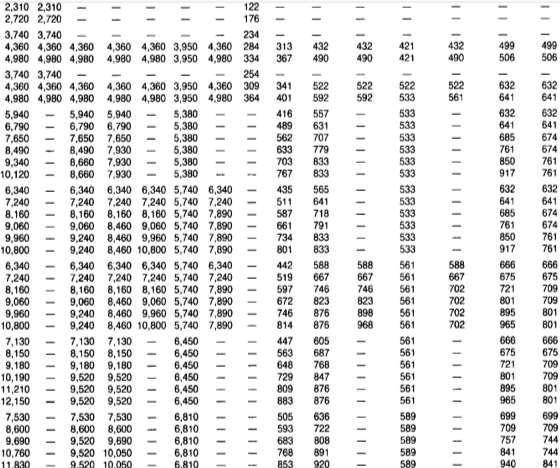
56 Vertical Depth (ft) APPENDIX I Pore and fracture pressure data: Pore Pressure (psi) Fracture pressure (psi) Vertical Depth (ft) Pore Pressure (psi) Fracture pressure (psi) Vertical Depth (ft) Pore Pressure (psi) Fracture pressure (psi)

57 APPENDIX II Performance properties of casing strings: Surface casing: 57
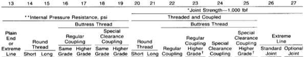
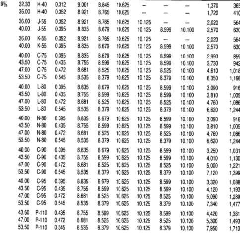
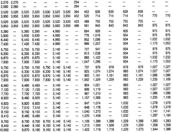
58 Intermediate casing: e casing: 58
59 Intermediate liner casing: 59

60 Production liner casing: 60
Casing Design. Casing Design. By Dr. Khaled El-shreef
 Casing Design By Dr. Khaled El-shreef 1 Casing Design CONTENTS Function of Casing Casing Types & Tools Strength Properties Casing Specification Casing Design 2 1 RUNNING AND CEMENTING CASING Reasons for
W I L D W E L L C O N T R O L PRESSURE BASICS AND CONCEPTS
 PRESSURE BASICS AND CONCEPTS Pressure Basics and Concepts Learning Objectives You will be familiarized with the following basic pressure concepts: Defining pressure Hydrostatic pressure Pressure gradient
Understanding pressure and pressure
 CHAPTER 1 1-1 PRESSURE BASICS Remember to think downhole. The concepts provided in this section cover the foundations for good well control. Understanding pressure and pressure relationships is important
Extended leak off testing
 Extended leak off testing Rev: 1.0 03/01/01 Purpose To ensure minimal operational time and risk exposure to personnel, process, production and equipment. The following extended leak off test procedures
APPENDIX A1 - Drilling and completion work programme
 APPENDIX A1 - Drilling and completion work programme Information about the well and drilling To the extent possible, the international system of units (SI) should be adhered to, and the drilling programme
SURFACE CASING SELECTION FOR COLLAPSE, BURST AND AXIAL DESIGN FACTOR LOADS EXERCISE
 SURFACE CASING SELECTION FOR COLLAPSE, BURST AND AXIAL DESIGN FACTOR LOADS EXERCISE Instructions Use the example well data from this document or the powerpoint notes handout to complete the following graphs.
A New and Simplified Method for Determination of Conductor Surface Casing Setting Depths in Shallow Marine Sediments (SMS)
") AADE-07-NTCE-41 A New and Simplified Method for Determination of Conductor Surface Casing Setting Depths in Shallow Marine Sediments (SMS) Paknejad, A., Texas A&M University; Schubert, J., Texas A&M University
AADE-07-NTCE-41 A New and Simplified Method for Determination of Conductor Surface Casing Setting Depths in Shallow Marine Sediments (SMS) Paknejad, A., Texas A&M University; Schubert, J., Texas A&M University
W I L D W E L L C O N T R O L FLUIDS
 FLUIDS Fluids Learning Objectives You will learn about different fluids that can be used in well control. You will become familiar with the characteristics and limitations of fluids. You will learn general
DAY ONE. 2. Referring to the last question, what mud weight would be required to BALANCE normal formation pressure?
 DAY ONE 1. Normal formation pressure gradient is generally assumed to be: A..496 psi/ft B..564 psi/ft C..376 psi/ft D..465 psi/ft 2. Referring to the last question, what mud weight would be required to
Rig Math. Page 1.
 Page 1 The Calculator and Main Keyboard Display Numerical 10-key pad used for entering numerical values Trigonometric Functions These keys will be used where wellbore angle is an issue These are the keys
Step-Rate Formation Integrity Test Method for Geothermal Wells
 GRC Transactions, Vol. 41, 2017 Step-Rate Formation Integrity Test Method for Geothermal Wells William M. Rickard, Ozgur Balamir and Ernesto Rivas Geothermal Resource Group, Inc. services@geothermalresourcegroup.com
Study Guide IADC WellSharp Driller and Supervisor
 Times to Flow Check: Before pulling out of the hole Before pulling BHA into the BOP When bit is pulled into the casing Increase in cuttings at shakers with same ROP On connections Upon abnormal trip tank
Casing! 07 An Overview!
 Casing! 07 An Overview! Introduction to Well Engineering - 07 - Casing 1 Contents 1. Introduction 4 2. Component Parts Of A Casing 7 3. Casing Terminology 8 3.1 Conductor Casing (30" O.D.) 9 3.2 Surface
Squeeze Cementing. Brett W. Williams Cementing Technical Advisor January 2016 Tulsa API Meeting
 Squeeze Cementing Brett W. Williams Cementing Technical Advisor January 2016 Tulsa API Meeting Definition Squeeze Cementing is the process of applying hydraulic pressure to force or squeeze a cement slurry
BLACK HILLS PLATEAU PRODUCTION COMPANY
 BLACK HILLS PLATEAU PRODUCTION COMPANY DRILLING PROGRAM Homer Deep Unit 9 11CH SHL: 300 FNL, 200 FWL, NWNW Sect. 9 T8S R98W BHL: 1350 FSL, 2100 FEL NWSE Sect. 15 T8S R98W Garfield & Mesa Counties, Colorado
Hard or Soft Shut-in : Which is the Best Approach?
 HARD - SOFT shut-in? Hard or Soft Shut-in : Which is the Best Approach? March '93 INTRODUCTION There is now reasonable acceptance through-out the industry for the use of a hard shut-in procedure following
OCEAN DRILLING PROGRAM
 BIH OCEAN DRILLING PROGRAM www.oceandrilling.org Scientifi c Application Packers A packer is an inflatable rubber element that inflates to seal the annular space between the drill string and the borehole
WILD WELL CONTROL WARNING SIGNS OF KICKS
 WARNING SIGNS OF KICKS Warning Signs of Kicks Learning Objectives You will learn the warning signs that indicate the well may be kicking: Warning signs of kicks False kick indicators You will also learn
Practice Exam IADC WellSharp Driller and Supervisor
 Workover & Completion Day 4 1. In a workover operation of a shut in well a Lubricator is being used together with a Wireline BOP / Wireline Valve. Which Barrier is classified as the Primary Barrier? A.
Worked Questions and Answers
 Worked Questions and Answers A Learning Document for prospective Candidates For the Rotary Drilling Well Control Test Programme Copyright, IWCF June 2000 Revision No.1, November 2000 IWCF 2000 page 1 of
Coal and Water Protection. PADEP: Well Plugging & Subsurface Activities Division Bureau of Oil and Gas Planning & Program Management
 Coal and Water Protection PADEP: Well Plugging & Subsurface Activities Division Bureau of Oil and Gas Planning & Program Management Review of Applicable Regulations & Laws Coal protective casing: A string
INTERMEDIATE CASING SELECTION FOR COLLAPSE, BURST AND AXIAL DESIGN FACTOR LOADS EXERCISE
 INTERMEDIATE CASING SELECTION FOR COLLAPSE, BURST AND AXIAL DESIGN FACTOR LOADS EXERCISE Instructions Use the example well data from this document or the powerpoint notes handout to complete the following
PTRT 1471: Exploration and Production I. Chapter 6: Drilling and Well Completion
 PTRT 1471: Exploration and Production I Chapter 6: Drilling and Well Completion Well Planning Drilling is a major investment (over $100m for offshore) Planning is aimed at maximizing investment Wells are
Casing and Cementing Requirements
 Directive PNG005 May 2018 Revision 2.0 Governing Legislation: Act: The Oil and Gas Conservation Act Regulation: The Oil and Gas Conservation Regulations, 2012 Order: 148/18 Record of Change Revision Date
Inflatable Packers for Grouting 11/10/00
 Introduction Inflatable Packers for Grouting 11/10/00 Inflatable packers are frequently used for grout injection in geotechnical applications for structural reinforcement and/or water-proofing of foundations,
Hydro-Mech Bridge Plug
 Manual No: 0620000303 Revision: F Approved By: Quality Engineer Date: 2014-9-9 Hydro-Mech Bridge Plug DESCRIPTION: Map Hydro-Mech Bridge Plug is hydraulically actuated and mechanically set. Compact, with
Why Do Not Disturb Is a Safety Message for Well Integrity
 Why Do Not Disturb Is a Safety Message for Well Integrity Presented at the Practical Well Integrity Conference 9-10 December, 2014 in Houston By Ron Sweatman, Principal Advisor, Reservoir Development Services,
Texas Administrative Code
 TITLE 16 PART 1 CHAPTER 3 RULE 3.13 Texas Administrative Code ECONOMIC REGULATION RAILROAD COMMISSION OF TEXAS OIL AND GAS DIVISION Casing, Cementing, Drilling, Well Control, and Completion Requirements
DIRECTIONAL DRILLING
 DIRECTIONAL DRILLING 1. General. Installation of pipelines through the levee embankment using directional drilling technology is prohibited. Installation of pipelines through a flood control project foundation
IWCF Equipment Sample Questions (Combination of Surface and Subsea Stack)
") IWCF Equipment Sample Questions (Combination of Surface and Subsea Stack) 1. Given the volumes below, how much hydraulic fluid will be required to carry out the following operations (no safety margin)?
IWCF Equipment Sample Questions (Combination of Surface and Subsea Stack) 1. Given the volumes below, how much hydraulic fluid will be required to carry out the following operations (no safety margin)?
Blowout during Workover Operation A case study Narration by: Tarsem Singh & Arvind Jain, OISD
 1. Introduction An incident of gas leakage from a well took place during workover operations. Subsequently, the gas caught fire on the fourth day in which twelve persons were injured. Two contract workers,
Chapter 5 HORIZONTAL DRILLING
 Chapter 5 HORIZONTAL DRILLING Chapter 5 How much money am I about to put on the table for a horizontal well? Did I do sufficient planning? Keys to Successful Horizontal Wells Multi-disciplined teams working
1. The well has been shut in on a kick and the kill operation has not started.
 Well Control Methods Day 2 1. The well has been shut in on a kick and the kill operation has not started. Shut in drill pipe pressure Shut in casing pressure 500 psi 700 psi After stabilization, both pressures
SUPPLEMENT Well Control for Drilling Operations Workover & Completion for Drillers Core Curriculum and Related Learning Objectives
 SUPPLEMENT Well Control for Drilling Operations Workover & Completion for Drillers Core Curriculum and Related Learning Objectives Form WSP-02-DO-SU-WOC-D Revision 0 13 February 2015 DC 2015 COPYRGHT PROTECTED
Casing Design for High Pressure/High Temperature Wells
 Casing Design for High Pressure/High Temperature Wells P. I. Edaigbini A. A. Maikobi Department of Petroleum Engineering, Abubakar Tafawa Balewa University, P.M.B.048, Bauchi, Nigeria Abstract A satisfactorily
Book 3 - Well Control Calculations
 Welltrain Distance Learning Programme - DRILLING CALCULATIONS www.welltrain.com.au Welltrain Distance Learning Programme Book 3 - Well Control Calculations 162 Colin Street, West Perth, WA 6005 Tel: +61
Model A Sleeve Valve Cement Retainer
 Ret. O.D. Model A Sleeve Valve Cement Retainer DIMENSIONAL DATA A B C D E F G H J K L M N P Q R 3.593 3.593 3.500 2.500 3.531 3.531 1.345 3.375.750.437 2.437 2.187 7.062 2.437 5.312 11.685 20.093 3.937
New generation of solid expandable liners help give operators a jump on trouble zones
 New generation of solid expandable liners help give operators a jump on trouble zones By Pat York, Weatherford SINCE SOLID EXPANDABLE technology has gained credibility as an effective contingency option,
August 21, Deepwater MPD / PMCD
 August 21, 2011 Deepwater MPD / PMCD Managed Pressure Drilling (MPD) Pressure held on top of riser while drilling. Drill in overbalance condition Pressurized Mud Cap Drilling (PMCD) Pressure of mud column
Solid Expandable Tubular Technology: The Value of Planned Installation vs. Contingency
 Solid Expandable Tubular Technology: The Value of Planned Installation vs. Contingency Chris Carstens Unocal Corporation 14141 Southwest Freeway Sugar Land, Texas 77478 Mike Breaux Unocal Corporation 14141
Permeability. Darcy's Law
 Permeability Permeability is a property of the porous medium that measures the capacity and ability of the formation to transmit fluids. The rock permeability, k, is a very important rock property because
IWCF Equipment Sample Questions (Surface Stack)
") IWCF Equipment Sample Questions (Surface Stack) 1. During a well control operation 4000 psi was shut in below the middle pipe rams. Ram type BOP data: Model: Cameron U type Rated Working Pressure: 15000
IWCF Equipment Sample Questions (Surface Stack) 1. During a well control operation 4000 psi was shut in below the middle pipe rams. Ram type BOP data: Model: Cameron U type Rated Working Pressure: 15000
ARTICLE. Overcome casing integrity issues in your plug-and-perf operations
 ARTICLE Overcome casing integrity issues in your plug-and-perf operations CONTENT A challenge to plug-and-perf success 3 Causes of casing restrictions 9 How extended-range frac plugs keep operations moving
The Alberta Energy Regulator (AER) has approved this directive on January 31, Introduction Purpose of This Directive...
 has approved this directive on January 31, Introduction Purpose of This Directive...") Directive 008 Release date: January 31, 2018 Effective date: January 31, 2018 Replaces previous edition issued February 29, 2016 Surface Casing Depth Requirements The Alberta Energy Regulator (AER) has
Directive 008 Release date: January 31, 2018 Effective date: January 31, 2018 Replaces previous edition issued February 29, 2016 Surface Casing Depth Requirements The Alberta Energy Regulator (AER) has
Drilling Efficiency Utilizing Coriolis Flow Technology
 Session 12: Drilling Efficiency Utilizing Coriolis Flow Technology Clement Cabanayan Emerson Process Management Abstract Continuous, accurate and reliable measurement of drilling fluid volumes and densities
Cased-Hole Logging Environment
 Cased-Hole Logging Environment 2 Planning a Production Logging Job Planning is an important part of a production logging job. Frequently these jobs can only be done in safety during daylight. Thus, the
VACUUM TESTING PRECAST CONCRETE MANHOLES
 1 OF 5 testing is a quick, safe and practical way to validate manhole system integrity. Manhole sections can be tested at the precast concrete plant prior to delivery or on site prior to backfilling. Here
3 1 PRESSURE. This is illustrated in Fig. 3 3.
 P = 3 psi 66 FLUID MECHANICS 150 pounds A feet = 50 in P = 6 psi P = s W 150 lbf n = = 50 in = 3 psi A feet FIGURE 3 1 The normal stress (or pressure ) on the feet of a chubby person is much greater than
Well Control Modeling Software Comparisons with Single Bubble Techniques in a Vertical Well
 Well Control Modeling Software Comparisons with Single Bubble Techniques in a Vertical Well Jace R. Larrison, P.E. Blowout Engineers, LLC Recent advances in well control modeling simulators have incorporated
RPSEA UDW Forum June 22 & 23, Secure Energy for America
 RPSEA UDW Forum June 22 & 23, 2010 Secure Energy for America PROJECT TEAM RPSEA Operator Advisory Committee Anadarko Chevron Shell ConocoPhillips Subcontractors IntecSea NOV CTES General Marine Contractors
Appendix M Structural Analysis of the Macondo #252 Work String. Appendix M Structural Analysis of the Macondo #252 Work String
 Appendix M Structural Analysis of the Macondo #252 Work String Appendix M Structural Analysis of the Macondo #252 Work String Structural Analysis of the Macondo #252 Work String SES Document No.: 1101190-ST-RP-0003
W I L D W E L L C O N T R O L CIRCULATION & WELL CONTROL
 CIRCULATION & WELL CONTROL Learning Objectives You will learn: The importance of pump rates and pressures during well control operations Pressure relationships Basic calculations necessary in well control
SUPPLEMENT Well Control for Drilling Operations Workover & Completion for Supervisors Core Curriculum and Related Learning Objectives
 SUPPLEMENT Well Control for Drilling Operations Workover & Completion for Supervisors Core Curriculum and Related Learning Objectives Form WSP-02-DO-SU-WOC-S Revision 0 13 February 2015 DC 2015 COPYRGHT
GEOTHERMAL WELL COMPLETION TESTS
 GEOTHERMAL WELL COMPLETION TESTS Hagen Hole Geothermal Consultants NZ Ltd., Birkenhead, Auckland, New Zealand. ABSTRACT This paper reviews the measurements that are typically made in a well immediately
Chapter 8: Reservoir Mechanics
 PTRT 1472: Petroleum Data Management II Chapter 8: Reservoir Mechanics - Reservoir drives Types of Natural Gas Reservoir Fluids Natural gas is petroleum in a gaseous state, so it is always accompanied
DB Bridge Plug. Features. Benefits. Applications
 DB Bridge Plug The WELLFIRST Premium Cast Iron Bridge Plug designed to run on electric line. Rated between 2000-10000-psi differential, and 300 F from above and below. Features Field Proven Design Constructed
OPERATING MANUAL DOUBLE ACTING DRILLING INTENSIFIER HYDRAULIC TYPE
 Page 1 of 8 OPERATING MANUAL DOUBLE ACTING DRILLING INTENSIFIER HYDRAULIC TYPE Size Series 6.50" 478 Reviewed And Approved By: Signature: Initials: Date: Page 2 of 8 Section OPERATING MANUAL DOUBLE ACTING
Casing Collapse Pressure for Non-zero Internal Pressure Condition. (Effect of Internal Pressure on Collapse)
") Casing Collapse Pressure for Non-zero Internal Pressure Condition (Effect of Internal Pressure on Collapse) Jiang Wu Chevron ETC August, 2011 API specifies casing collapse rating primarily based on casing
Casing Collapse Pressure for Non-zero Internal Pressure Condition (Effect of Internal Pressure on Collapse) Jiang Wu Chevron ETC August, 2011 API specifies casing collapse rating primarily based on casing
Department of Civil & Geological Engineering GEOE Engineering Geology
 Department of Civil & Geological Engineering GEOE 218.3 Engineering Geology Assignment #3, Head, Pore Pressure & Effective Stress Due 08 Oct, 2010 NOTE: Numbered subscripts indicate depth, in metres, below
RULES OF THE OIL AND GAS PROGRAM DIVISION OF WATER RESOURCES CHAPTER DRILLING WELLS TABLE OF CONTENTS
 RULES OF THE OIL AND GAS PROGRAM DIVISION OF WATER RESOURCES CHAPTER 0400-52-06 DRILLING WELLS TABLE OF CONTENTS 0400-52-06-.01 Drilling Equipment 0400-52-06-.03 Casingheads 0400-52-06-.02 Blowout Prevention
An Introduction to Deep Foundations
 An Introduction to Deep Foundations J. Paul Guyer, P.E., R.A. Paul Guyer is a registered mechanical engineer, civil engineer, fire protection engineer and architect with over 35 years experience in the
INSTALLING AN INEXPENSIVE AIR LINE TO MEASURE WATER DEPTHS IN WELLS
 INSTALLING AN INEXPENSIVE AIR LINE TO MEASURE WATER DEPTHS IN WELLS Joe Henggeler Extension Agricultural Engineer-Irrigation An inexpensive, yet highly accurate, device to measure the depth to water in
SIMULATION OF A RE-ENTRY WITH CASING DRILLING UNDER HPHT CONDITIONS Gabriella Federer-Kovacs 1. Introduction
 Simulation of a re-entry with casing drilling under HPHT conditions SIMULATION OF A RE-ENTRY WITH CASING DRILLING UNDER HPHT CONDITIONS Gabriella Federer-Kovacs 1. Introduction Due to the ongoing depletion
ECD Reduction Tool. R. K. Bansal, Brian Grayson, Jim Stanley Control Pressure Drilling & Testing
 ECD Reduction Tool R. K. Bansal, Brian Grayson, Jim Stanley Control Pressure Drilling & Testing Drilling Engineering Association, Fourth Quarter Meeting November 20, 2008 1 Presentation outline Description
Along-string pressure, temperature measurements hold revolutionary promise for downhole management
 Along-string pressure, temperature measurements hold revolutionary promise for downhole management IT S WIDELY KNOWN that the majority of stuck pipe incidents occur while pulling out of hole. If we can
EXAMINER S REPORT AND RECOMMENDATION STATEMENT OF THE CASE
 OIL AND GAS DO0KET NO. 01-0249550 THE APPLICATION OF REGENCY FS LP UNDER RULE 36 AND RULE 46 TO DISPOSE OF OIL AND WASTE CONTAINING HYDROGEN SULFIDE GAS INTO ITS TILDEN GPI WELL NO. 1, TILDEN, S. (WILCOX
SCORPION HIGH-QUALITY, FULLY COMPOSITE PLUGS
 SCORPION HIGH-QUALITY, FULLY COMPOSITE PLUGS A DIFFERENT KIND OF ENERGY COMPANY Nine Energy Service isn t your typical oilfield services company. Our success stems from a culture driven by performance
North American sealing solutions Bridge Plug Ball Drop Frac Plug Caged Ball Frac Plug
 North American sealing solutions Bridge Plug Ball Drop Frac Plug Caged Ball Frac Plug The North American Sealing Solutions composite bridge plug, caged ball and ball drop (flow thru) frac plug provide
INTERPRETATION NOTE ISSUED UNDER THE PETROLEUM DRILLING REGULATIONS (CNR 1150/96)
") BOP CLASSIFICATION SYSTEM FOR ONSHORE NEWFOUNDLAND AND LABRADOR INTERPRETATION NOTE ISSUED UNDER THE PETROLEUM DRILLING REGULATIONS (CNR 1150/96) PREPARED BY THE PETROLEUM RESOURCE DEVELOPMENT DIVISION
BOP CLASSIFICATION SYSTEM FOR ONSHORE NEWFOUNDLAND AND LABRADOR INTERPRETATION NOTE ISSUED UNDER THE PETROLEUM DRILLING REGULATIONS (CNR 1150/96) PREPARED BY THE PETROLEUM RESOURCE DEVELOPMENT DIVISION
OPTIMUM SELECTION OF WELL CONTROL METHODS
 OPTIMUM SELECTION OF WELL CONTROL METHODS Md AHAMMAD SHARIF Assistant professor, Department of Petroleum Engineering, GIET College of Engineering, Rajahmundry. Dr. S. SRIGOWRI REDDY Professor, GIET College
SUBSEA KILL SHEET EXERCISE No. 5
 Subsea Kill Sheet Exercise No. 5 SUBSEA KILL SHEET EXERCISE No. 5 Name: Date: Complete the Subsea vertical kill sheet provided on pages 2 and 3. Then answer questions 1 to 12. Please round calculations
W I L D W E L L C O N T R O L SHUT-IN PROCEDURES
 SHUT-IN PROCEDURES Shut-in Procedures Learning Objectives You will learn general shut-in procedures: For surface BOPs. For subsea BOPs. You will learn to interpret shut-in pressures and be able to perform
VOLUMETRIC METHODS and STRIPPING OPERATIONS
 VOLUMETRIC METHODS and STRIPPING OPERATIONS WELL CONTROL SCHOOL Muscat, Oman Training Center VOLUMETRIC METHODS and STRIPPING OPERATIONS The material contained here, is based on the best sources available
GEOTHERMAL WELL DESIGN USING THE NEW 2015 NEW ZEALAND STANDARD AND 1991 STANDARD: A CASE OF MW-20A IN MENENGAI, NAKURU COUNTY, KENYA
 Orkustofnun, Grensasvegur 9, Reports 2015 IS-108 Reykjavik, Iceland Number 28 GEOTHERMAL WELL DESIGN USING THE NEW 2015 NEW ZEALAND STANDARD AND 1991 STANDARD: A CASE OF MW-20A IN MENENGAI, NAKURU COUNTY,
Testing Services Overview
 2 Jet Research Center JRC Jet Research Center Perforating Center of Excellence Testing Services Overview API RP19B Testing Advanced Testing Operational Testing API RP19B Testing The American Petroleum
Engineered solutions for complex pressure situations
 SPECIAL SERVICES Engineered solutions for complex pressure situations Cudd Energy Services (CES) delivers custom engineered solutions to resolve complex pressure situations resulting from equipment failure
Advanced Applications of Wireline Cased-Hole Formation Testers. Adriaan Gisolf, Vladislav Achourov, Mario Ardila, Schlumberger
 Advanced Applications of Wireline Cased-Hole Formation Testers Adriaan Gisolf, Vladislav Achourov, Mario Ardila, Schlumberger Agenda Introduction to Cased Hole Formation tester Tool specifications Applications
Success Paths: A Risk Informed Approach to Oil & Gas Well Control
 API Winter E&P Standards Conference, Austin January 18, 2017 Success Paths: A Risk Informed Approach to Oil & Gas Well Control Dr. Dan Fraser Director, Strategic Alliances for Global Energy Solutions,
On-Off Connector Skirt
 On-Off Connector Skirt Retrievable Packers & Accessories The On-Off Connector Skirt is compact, reliable, fully sealing, J-type tubing disconnect device that automatically engages and releases with a small
Restoring Fluid Flow in Tubing Strings
 Restoring Fluid Flow in Tubing Strings Andrew Roth, Product Manager Fike Corporation Fike Hydraulic Tubing Drains (HTD) for use with deep hole drilling tools, downhole devices and other oil and off shore
Bridge Plugs, Ball Drop & Caged Ball Plugs For Zone Isolation
 Bridge Plugs, Ball Drop & Caged Ball Plugs For Zone Isolation ADVANTAGE composite bridge plug, caged ball and ball drop (flow thru) frac plug provide a means to isolate multiple zones during high pressure
Inflatable Packer Single & Double. Single & Double Packer Dimension. Wireline Packer. Water Testing Packer (WTP) Packer
 Packer") Inflatable Packer Single & Double Single & Double Packer Dimension Wireline Packer Water Testing Packer (WTP) Packer Packer Working Pressure & Depth Chart Packer Water Hand Pump Packer Air Driven Pump
Inflatable Packer Single & Double Single & Double Packer Dimension Wireline Packer Water Testing Packer (WTP) Packer Packer Working Pressure & Depth Chart Packer Water Hand Pump Packer Air Driven Pump
Recommended minimum functional specifications and standards for geothermal wells in the Netherlands v.5
 Recommended minimum functional specifications and standards for geothermal wells in the Netherlands v.5 1. Introduction... 1 2. Rationale... 2 3. Minimum functional specifications... 5 4. Minimum standards
Tibor Szabó DRILLING THROUGH SHALLOW GAS ZONES IN HUNGARY
 Tibor Szabó Petroleum Engineering Department University of Miskolc, Hungary DRILLING THROUGH SHALLOW GAS ZONES IN HUNGARY The prospecting activity for CH is more than 60 years old in Hungary. During this
Perforating Options Currently Available in Horizontal Shale Oil and Gas Wells. Kerry Daly, Global BD Manager- DST TCP
 MENAPS 2013 Perforating Options Currently Available in Horizontal Shale Oil and Gas Wells Kerry Daly, Global BD Manager- DST TCP MENAPS 13-17 WELL FLOW MANAGEMENT TM Scope/ Contents: MENAPS 13-17 Study
COURSE NUMBER: ME 321 Fluid Mechanics I Fluid statics. Course teacher Dr. M. Mahbubur Razzaque Professor Department of Mechanical Engineering BUET
 COURSE NUMBER: ME 321 Fluid Mechanics I Fluid statics Course teacher Dr. M. Mahbubur Razzaque Professor Department of Mechanical Engineering BUET 1 Fluid statics Fluid statics is the study of fluids in
OIL AND GAS DOCKET NO
 OIL AND GAS DOCKET NO. 09-0241077 THE APPLICATION OF GILBOW TANK TRUCK SERVICE, INC., TO DISPOSE OF OIL AND GAS WASTE BY INJECTION INTO A POROUS FORMATION NOT PRODUCTIVE OF OIL OR GAS, GILBOW WELL NO.
Next Generation Quartz Pressure Gauges
 Next Generation Quartz Pressure Gauges Rick Puccio, Ph.D. Senior Scientist Quartzdyne Houston, TX March 2, 2016 Outline Quartz Pressure Gauge Introduction Gauge Size Reduction Long Term Pressure Drift
RIGID RISERS FOR TANKER FPSOs
 RIGID RISERS FOR TANKER FPSOs Stephen A. Hatton 2H Offshore Engineering Ltd. SUMMARY Recent development work on the subject of dynamic rigid (steel pipe) risers demonstrates that their scope of application
Representing EXAMINERS REPORT AND PROPOSAL FOR DECISION STATEMENT OF THE CASE
 OIL AND GAS DOCKET NO. 03-0231502 THE APPLICATION OF JOHNSON SANFORD OPERATING COMPANY TO AMEND ITS PERMIT TO DISPOSE OF OIL AND GAS WASTE BY INJECTION INTO A POROUS FORMATION PRODUCTIVE OF OIL OR GAS,
Oil, Gas and Salt Resources of Ontario
 Oil, Gas and Salt Resources of Ontario Provincial Operating Standards Version 2.0 Oil, Gas and Salt Resources of Ontario Provincial Operating Standards, Version 2.0 Version 2.0 of the Oil, Gas and Salt
Perforation Design for Well Stimulation. R. D. Barree Barree & Associates LLC
 Perforation Design for Well Stimulation R. D. Barree Barree & Associates LLC Typical Shaped Charge Primer charge Main explosive charge Case or container Detonating cord groove ¾ point of initiation Liner
EVALUATION OF LIQUID LIFT APPROACH TO DUAL GRADIENT DRILLING
 EVALUATION OF LIQUID LIFT APPROACH TO DUAL GRADIENT DRILLING A Thesis by UGOCHUKWU NNAMDI OKAFOR Submitted to the Office of Graduate Studies of Texas A&M University in partial fulfillment of the requirements
GEOTHERMAL WELL DESIGN
 GEOTHERMAL TRAINING PROGRAMME Reports 2013 Orkustofnun, Grensasvegur 9, Number 28 IS-108 Reykjavik, Iceland GEOTHERMAL WELL DESIGN Abdirasak Omar Moumin Ministry of Energy and Natural Resources P.O. Box
WellCAP IADC WELL CONTROL ACCREDITATION PROGRAM
 WellCAP IADC WELL CONTROL ACCREDITATION PROGRAM WELL SERVICING OPERATIONS (WIRELINE, COILED TUBING & SNUBBING) CORE CURRICULUM AND RELATED FORM WCT-2WSI INTRODUCTORY LEVEL For information on how an course
Берг АБ Тел. (495) , факс (495) Turning Ideas Into Engineered Solutions KAYDON RING & SEAL, INC.
 , факс (495) Turning Ideas Into Engineered Solutions KAYDON RING & SEAL, INC.") Turning Ideas Into Engineered Solutions RING & SEAL, INC. K-CBS Series Circumferential Barrier Seals Kaydon s high performance circumferential barrier seals back up DGS systems with performance & economy.
Turning Ideas Into Engineered Solutions RING & SEAL, INC. K-CBS Series Circumferential Barrier Seals Kaydon s high performance circumferential barrier seals back up DGS systems with performance & economy.
 Hydrostatic pressure Consider a tank of fluid which contains a very thin plate of (neutrally buoyant) material with area A. This situation is shown in Figure below. If the plate is in equilibrium (it does
Float Equipment TYPE 925/926
 Type 925 Float Collar Plunger Valve Float Equipment For less demanding well conditions, such as shallower depths or lower pressures, Top- Co offers economical float equipment certified to API RP 10F category
PowerDrive X6. Rotary Steerable System for high-performance drilling and accurate wellbore placement
 Rotary Steerable System for high-performance drilling and accurate wellbore placement The PowerDrive X6 RSS maintains control under the most difficult conditions, bringing the benefits of rotary steerable
The SPE Foundation through member donations and a contribution from Offshore Europe
 Primary funding is provided by The SPE Foundation through member donations and a contribution from Offshore Europe The Society is grateful to those companies that allow their professionals to serve as