WIM WOBBE INDEX METER Installation, operation and maintenance manual
|
|
|
- Rudolf Chambers
- 5 years ago
- Views:
Transcription

1 WIM WOBBE INDEX METER Installation, operation and maintenance manual Hobré Instuments B.V.
2 Revision:July 2004
3 Document Label Definitions Symbol Label Description WARNING: CAUTION: CAUTION: NOTE: Consists of conditions, practices, or procedures that must be observed to prevent personal injury. Consists of conditions, practices, or procedures that must be observed to prevent injury or equipment damage. Risk of electric shock. May result in injury if proper precautions are not taken. Emphasises important or essential information. Please refer to Chapter 1 for important safety information and instructions on how to use this manual. Copyright 2004 by Hobré Instruments All rights reserved
4
5 1. SAFETY CONSIDERATIONS INSTRUCTIONS AND PROCEDURES GENERAL SAFETY AND OPERATING INFORMATION GENERAL PRECAUTIONS ELECTRICAL POWER SYSTEM LOCATION BOTTLE GAS FILTERS VALVES VENTS SPECIFIC SAFETY CONSIDERATIONS FOR EX- UNITS THE WIM-9900 WOBBE INDEX METER FIELDS OF APPLICATION FEATURES INPUTS AND OUTPUTS CONSUMABLES THE PRINCIPLE OF OPERATION OXYGEN IS THE BASE FOR THE WOBBE INDEX MEASUREMENT THE DETERMINATION OF THE AMOUNT OF RESIDUAL OXYGEN CALCULATING RESIDUAL OXYGEN FROM THE CELL MVOLT SIGNAL. (NERNST-EQUATION) WHY MEASURE BOTH WOBBE AND CARI INDEX ANALYSER CALIBRATION AND THE TERMS SLOPE AND OFFSET THE TERMS "UPPER HEATING VALUE" AND "LOWER HEATING VALUE" SAMPLE CONDITIONING SYSTEM THE MAIN EXECUTIONS BASIC OPERATION OF THE SAMPLE CONDITIONING SYSTEM (SCS) FUNCTION OF THE INSTRUMENT AIR PRESSURE VERSION SAMPLE CONDITIONING SYSTEM (WIM-9900P) LOW PRESSURE VERSION SAMPLE CONDITIONING SYSTEM (WIM-9900LP) THE EXTENDED RANGE VERSION THE DENSITY (OR SPECIFIC GRAVITY) METER THE ELECTRONICS GENERAL INSTALLATION MECHANICAL HOOK-UP POINTS OF ATTENTION FOR SAMPLE SUPPLY POINTS OF ATTENTION FOR OVEN VENT AND DRAIN POINTS OF ATTENTION FOR ATMOSPHERIC VENT LINES SWAGELOK INSTRUCTION ELECTRICAL HOOK-UP CONNECTING POWER CONNECTING DIGITAL IN- & OUTPUT CONNECTING ANALOGUE SIGNALS START-UP GENERAL ON-SITE SUPPORT & TRAINING van 61
6
7 7.3 PRECAUTIONS UPON START-UP START-UP SAMPLE SYSTEM SETTING THE BOOSTER REGULATOR DETERMINING THE CORRECT ORIFICE SIZE AND CALIBRATION GASSES IN OPERATION GENERAL HOW TO READ THE DISPLAY DISPLAYED OUTPUT ABBREVIATIONS DISPLAYED INPUT ABBREVIATIONS THE SOFTWARE MENUS (8.5) 1. Global Settings Menu (8.5) 1.1 Calibration Settings (8.5) 1.2 Current Outputs A, B (8.5) 1.3 Current Outputs C, D (8.5) 1.4 Oxygen Parameters (8.5) 1.5 Wobbe, Cari, Calorific Options (8.5) Wobbe Index Parameters (8.5) CARI Index Parameters (8.5) Calorific Value Parameters (8.5) 1.6 Other Options (8.5) Mode Normal Layout (8.5) Mode Values Layout (8.5) Mode Others Layout (8.5) Mode Calibrating Layout (8.5) Temperature Settings (8.5) Dual Range Parameters (8.5) Multi-stream Parameters (8.5) 3. Calibration (8.5) 3.1 Edit Cal Gas Parameters (8.5) 3.2 Calibration Schedule (Weekly) (8.5) 3.2 Calibration Schedule (Repeat) (8.5) 3.3 Start Calibration (8.5) 3.4 Start Validation (8.5) 4. Alarm Reset (8.5) 5. Login (8.5) 5.1 Login Menu (8.5) 5.* Logged In *(8.5) 6 Measuring Menu (8.5) 7.* Test Menu (8.5) 7.1* Test Digital Outputs I (8.5) 7.2* Test Digital Outputs II (8.5) 7.3* Test Analogue Outputs A/B (8.5) 7.4* Test Analogue Outputs C/D (8.5) 8. System Settings (8.5) 8.1* Channel Routing Inputs (8.5) 8.2* Channel Routing Outputs I (8.5) 8.3* Channel Routing Outputs II (8.5) 8.4* Channel Routing Outputs III (7.5) 8.5* Polarity Inputs (8.5) 8.6* Polarity Outputs I (8.5) 8.7* Polarity Outputs II (8.5) 8.8* Save Changes And Restart van 61
8
9 9.0 MAINTENANCE AND INSPECTION GENERAL MAINTENANCE MAINTAINING THE SAMPLE FILTER MAINTAINING THE PRESSURE REGULATOR STATIONS (PILOT & COMBUSTION AIR) MAINTAINING THE SAMPLE PRESSURE REGULATOR MAINTAINING THE BOOSTER REGULATOR REPLACING THE ORIFICES TUBES IN THE MIXING CHAMBER INSPECTION OF THE FLOW METERS INSPECTION OF THE PRESSURE RELIEF VALVES REPLACEMENT OF THE ZIRCONIA OXIDE CELL SPARE PARTS TROUBLESHOOTING AND ERROR MESSAGES TROUBLESHOOTING ERROR MESSAGES SPECIFICATIONS PERFORMANCE UTILITIES CONSUMPTION ENVIRONMENTAL REQUIREMENTS DIMENSIONS & WEIGHT LIST OF AVAILABLE OPTIONS CE DECLARATION OF CONFORMITY van 61
10
11 1. Safety Considerations WARNING: Failure to follow appropriate safety procedures or inappropriate use of the equipment described in this manual can lead to equipment damage or injury to personnel. Any person working with or on the equipment described in this manual is required to evaluate all functions and operations for potential safety hazards before commencing work. Appropriate precautions must be taken as necessary to prevent potential damage to equipment or injury to personnel. The information in this manual is designed to aid personnel in the correct and safe installation, operation, and maintenance of the systems described. However, personnel must consider all actions and procedures for potential hazards or conditions that may not have been anticipated in the written procedures. If a procedure cannot be performed safely, it must not be performed until appropriate actions can be taken to ensure the safety of equipment and personnel. The procedures in this manual are not designed to replace or supersede required or common sense safety practices. All safety warnings listed in any documents applicable to equipment and parts used in or with the system described in this manual must be read and paid attention to before commencing work on any part of the system. Failure to correctly perform the instructions and procedures in this manual or other documents pertaining to this system can result in equipment malfunction, equipment damage, and injury to personnel. The following symbols are used throughout this manual to alert users to potential hazards or important information. Document Label Definitions Symbol Label Description WARNING: CAUTION: CAUTION: NOTE: Consists of conditions, practices, or procedures that must be observed to prevent personal injury. Consists of conditions, practices, or procedures that must be observed to prevent injury or equipment damage. Risk of electric shock. May result in injury if proper precautions are not taken. Emphasises important or essential information. 5 van 61
12
13 1.2 Instructions and Procedures This manual makes extensive use of step-by-step instructions and procedures. The listed functions should be performed in the order shown to ensure proper functioning of the equipment. Particular attention must be paid to any safety warnings or cautions that may be listed. WARNING: Deviation from the specified instruction or procedure steps may result in equipment malfunction, equipment damage, or injury to personnel. 1.3 General Safety and Operating Information This section contains general safety and operating information applicable to analyser systems. This information must be understood by all persons installing, using, or maintaining the analyser system. This information is designed to aid personnel in safe installation, operation, and service of the analyser and sample systems. It is not designed to replace or limit appropriate safety measures applicable to work performed by personnel. Any additional safety and operating measures that are required must be determined by and followed by personnel performing work on the system. WARNING: Failure to pay attention to the following information may lead to equipment damage or injury to personnel. 1.4 General Precautions Protective eyewear (glasses with side shields or goggles as appropriate) must be worn when servicing any part of the analyser or sample system. When servicing the sample system, chemical resistant gloves appropriate for the materials in the system must be worn. When servicing the hot analyser oven, internal components, or hot sample system components, appropriate gloves must be worn. Heated components should be allowed to cool before servicing if possible. Other appropriate equipment or clothing must be used as required by the type of work performed. WARNING: Ovens, internal components, and sample system components may be hot even when power is not applied to the unit. Take appropriate precautions to prevent injury from contact with hot items. All applicable regulations and procedures must be followed for the work performed. Before beginning any work on the system, carefully consider all the potential hazards 6 van 61
14
15 and ensure that appropriate measures are taken to prevent injury to personnel or equipment damage. 1.5 Electrical Power CAUTION: Attempting to perform electrical procedures without turning off the power could result in an electrical shock hazard to personnel and damage to the Wobbe analyser! The system uses AC power at 115 or 220 volts. The AC power is converted to DC at several voltage levels. Appropriate precautions must be taken to prevent sparks that may ignite combustible materials that may be present in the analyser environment. Precautions must also be taken to prevent electrical shock if the analyser or sample system enclosures are opened. The AC power to the system must be free from noise, surges, sags, and spikes for proper operation of the system. AC power circuit breakers and wiring must be sized properly for the required current. All wiring installations must meet applicable electrical codes. 1.6 System Location The analyser and sample system must be located suitably. The system must not be installed in an area classification for which it is not rated. The equipment must be protected from temperature and humidity extremes. The analyser must not be mounted in an area with potentially corrosive atmosphere or high vibration. The system components must be attached securely and appropriately to a floor or wall. The system must be mounted to permit adequate access for operation and maintenance. 1.7 Bottle Gas WARNING: Bottles typically have very high pressures and may result in serious injury to personnel if the bottle valve is opened without a regulator attached or if the valve is broken off the bottle. See the following paragraphs for more information. The analyser system typically uses bottled gasses. The bottled gases are typically maintained at very high pressure. Severe injury to personnel and equipment can occur if the bottle gas valve is damaged or opened without installing an appropriate regulator. A protective cap must be in place over the bottle valve any time the bottle is moved. Do not move a bottle with the regulator attached or if the protective cap is missing. Bottles must be secureled chained in place at all times when the protective cap is removed. To permit replacing empty bottles, valves must be installed with extra bottle regulators to permit selecting between two bottles of gas without interrupting gas flow 7 van 61
16
17 to the system. Appropriate pressure relief systems must also be installed. Gas type and locations must be clearly marked to prevent connecting the wrong gas type to the system. 1.8 Filters Filters are used to reduce sample system maintenance requirements by removing particulate material from the sample. Periodically, filters must be replaced or cleaned. All pressure must be removed from the filter before servicing. The filter and associated sample system must be decontaminated appropriately before removal or service. Used filters or filter elements must be dispose in compliance with all applicable regulations for the potential materials filtered and the material from which the filter was constructed. Filters or elements which need replacement should be replaced by original parts only. 1.9 Valves 1.10 Vents Valves can leak through or leak out. When opening the sample system, precautions must be taken to prevent injury to personnel or damage to equipment in the event that a valve leaks or is misaligned. Before removing or disconnecting any valve, hazardous materials must be thoroughly removed from the valve internals and all pressure must be relieved. When installing a new or serviced valve, all fittings and surfaces must be checked for leaks. Vents are used to expel the spent gases from the analyser system. The vents must be routed to a safe location as necessary to prevent injury to personnel. Backpressure must be kept to an absolute minimum to prevent degrading system performance. Long vent runs must be avoided. 8 van 61
18
19 1.11 Specific safety considerations for Ex- units Make sure that the "special conditions for safe use" as described within the Excertificate, Kema 03.ATEX.2410 X have been read and understood. Make sure that the area for which the unit is intended complies with the gasgroup and temperature class for which the unit has been certified. Make sure that the power supply tension complies with the power supply dat as mentioned on the type plate. 9 van 61
20
21 Power connection to the unit has to be done in the Exd power connection box. Hook up of the power cable and transit into the power box has to comply with the regulations of EN Signal connection to the unit has to be done in the Exd signal connection box. Hook up of the signal cables and transit into the signal box has to comply with the regulations of EN Make sure that the manual has been read and understood in its full before operating or servicing the unit Make sure that all mechanical utility, sample, vent and drain connections are made in accordance with the instruments drawings. The unit contains hot surfaces in both the sampling conditioning compartment (left hand) and the oven compartment (right hand bottom). Window may only be cleaned with a damped cloth to avoid built-up and release of static energy. Don not use dry cloth!! 10 van 61
22
23 Installation instructions for ATEX Ex units (Inserted copy of certificate texts from 03.ATEX.2410 X) The intrinsically safe circuits of the above mentioned barriers and/or isolators shall be installed in such a way that separation is guaranteed between the different circuits or voltage and/or current addition shall be taken into account at places where the circuits can come into contact with each other. Where applicable the earth connection of the above mentioned barriers shall be connected to the potential equalizing system within the hazardous area. This may also be achieved via an earth collecting rail within the analyser. The screens of the cables shall be connected to the enclosure of the analyser. This may also be achieved via an earth collecting rail within the analyser. When the screens are also earthed at the other side of the cable, the potential equalizing system shall assure that the current capability of the screen is capable for the expected currents through it. The cable entry devices and closing devices for unused openings on the pressurized enclosure shall be in type of explosion protection flameproof enclosure "d" or increased safety "e", suitable for the conditions of use and correctly installed. The cable entry devices and closing devices for unused openings on the control boxes shall be in type of explosion protection flameproof enclosure "d", suitable for the conditions of use and correctly installed. For external earthing or bonding connection a cable lug shall be used so that the conductor is secured against loosening and twisting and that contact pressure is permanently secured. Special conditions for safe use for ATEX Ex units (Inserted copy of certificate texts from 03.ATEX.2410 X) Energizing the electrical apparatus by using the bypass function of the purge control unit or remote bypass switch located near the control unit is only permitted with permission of the works manager or his proxy. This permission may only be given when it is made sure that during the time the system is energized by using this switch an explosive atmosphere is not present or when the necessary protective measures against explosion hazard have been taken ("hot permit"). The enclosure may not be opened when an explosive gas atmosphere is present. All externally powered input signals into the pressurized enclosure shall be isolated by external relays controlled by the purge control unit. 11 van 61
24 GENERAL LAY-OUT WOBBE INDEX METER WIM-9900
25 2. The WIM-9900 Wobbe Index Meter 2.1 Fields of application Hobré instruments Wobbe Index Meter has specifically been designed for process control applications. Its most common use is analysis of fuel gas supply for feed forward or feed backward control of burners and boilers that can be exposed to sudden changes in the fuel gas composition. The analyser enables users to control the air / fuel ratio with a maximum efficiency and minimum temperature disturbance. Another main field of application is mixture control of gasses based on heating value. Its rugged design makes it suitable for usage in chemical and petrochemical environments. When desired it can be supplied in an explosion proof execution for both European as well as American markets. Hobré instruments is by its origin an analyser system integrator and has experience in designing and building of instrumentation systems for almost 25 years. This experience enables us to offer user specific applications to the analyser system, for instance for the measurement of very wet gasses or multiple fuel lines. 2.2 Features Especially the response time of the analyser makes it superior to competitive types of analysers. Since the measuring principle is based on a electrochemical reaction in a Zirconium Oxide cell it can operate on a flame-less base, this enables the fast response time over most conservative analysers that are usually based on a flame and thermocouple measurement. This also enables the analyser to measure gasses with low Wobbe Indexes. The analyser operates without any moving parts which results in a minimum of maintenance. Its design enables easy replacement of parts. These benefits result in a low cost of ownership and minimum down time. Its controller is based on a normal PC and features user friendly software and trend display on the control screen. The software enables users to do automatic (remote) calibration based on a time interval or a calibration time schedule. Input of a calibration or validation command can be given from a control room or DCS system. The measurement itself is insensitive to ambient temperature variations, there is no specific need for an air-conditioned environment. Without specific applications it can be used in ambiences varying between 0 and 40 C. With some applications it can be used in ambiences between -15 and +60 C. 2.3 Inputs and outputs The analyser features as a standard two analogue output channels. As an option this can be extended to four. Output possibilities are Wobbe, CARI (Combustion Air Requirement Index), Specific Gravity (when equipped with the optional Density meter) and calorific value. These indexes can be programmed to several dimensions (European and American dimensions). A wide range of alarm outputs is available. When desired these can be relay isolated contacts. 12 van 61
26
27 2.4 Consumables The Wobbe Index Meter requires the supply of dry and oil free instrument air and as a minimum two calibration gasses, in case of an extended range version three calibration gasses. For details please refer to the utilities and specifications section. 13 van 61
28 SAMPLE COMBUSTION OVEN WIM-9900 ZIRCONIUM OXIDE CELL WIM-9900
29 3. The principle of operation 3.1 Oxygen is the base for the Wobbe Index measurement For the combustion of gas, air is required. When supplying the right quantity of air, the gas will completely burn. This is the so-called stoichiometric air requirement of the gas. Because of this, the Wobbe-index can also be seen as a value for the need of air in gas. By burning the gas with a small excess of air, the flue gas will contain the remaining oxygen from the air, which has not taken part in the combustion. When the Wobbe-index of a gas changes, the stoichiometric air requirement and the percentage of the remaining oxygen in the flue gas will change simultaneously. The above makes the residual Oxygen a good parameter to base a Wobbe Index value on and that is exactly what is being done within the WIM The determination of the amount of Residual Oxygen Within the analyser the sample gas is mixed with an excess of air. This mixture is directed to an oven heated to a temperature over 800 C. In the first stage of the oven the mixture is burnt catalytically. In the second stage the mixture that has now become a flue gas with residual Oxygen is introduced to an Oxygen sensor. The oxygen sensor in the oven is a Zirconium oxide cell. This cell is a hollow rod from which the outside is exposed to the flue gas whilst the inside has an open connection to atmosphere. To the cell two Pt-electrodes are fixed, the positive one on the outside (gas-side) and the negative one on the inside (atmospheric side). At high temperatures, over 600 C, Oxygen molecules can diffuse through the Zirconium oxide by picking up two electrons from the negative Pt electrode. The Oxygen than moves through as Oxygen-ions, at the outer side of the Zirconium oxide they are converted back again to gaseous Oxygen by release of the two electrons. The thus created electrochemical process can be compared with that of a battery, but with gaseous reactants. The driving force of this process is manifested as an electrical potential difference over the two electrodes in the form of a mv signal. As long as the oxygen concentration of the burning gas is equal to that of the outside air there will be no driving force. However, as soon as there is a difference in partial oxygen presence a potential difference will develop over the electrodes. So the extent of this potential difference is a function of the difference in oxygen concentration. 14 van 61
30
31 3.3 Calculating residual Oxygen from the cell mvolt signal. (Nernst-equation) The relation between the cell voltage and the oxygen concentration in the flue gas is given by the Nernst equation. E = R T 4 F α ln 0 α With: E = Cell voltage in V R = Gas constant in J/molK F = Constant of Faraday in C/mol T = Temperature in the oven in K α 0 = Oxygen concentration in the outside air in % α = Oxygen concentration in the flue gas % The millivoltage is not completely linear with the Oxygen concentration, this relation is linearised within the analysers control unit. The now linearised milli voltage signal is now used to determine the residual Oxygen percentage. This is done using the formula hereunder. α = α 0 e E 4 F R T With: α = Oxygen concentration in the burning gas in % α 0 = Oxygen concentration in the outside air in % E = Cell voltage in V R = Gas constant in J/molK F = Constant of Faraday in C/mol T = Temperature in the oven in K e = Constant 2,718 To convert the residual Oxygen percentage to a Wobbe Index value the analyser is calibrated with two gasses with known Wobbe Index values. A low calibration gas with a low (known) Wobbe Index value and a high calibration gas with a high (known) Wobbe Index value. Now the (unknown) Wobbe index value of sample gas can be determined using the following formula. With: W W ( α h ) Wh h l Wobbe = α + αh αl W h = Calibration gas, high Wobbe-value in MJ/Nm 3 W l = Calibration gas, low Wobbe-value in MJ/Nm 3 α h = Oxygen concentration in burning gas at high Wobbe in % 15 van 61
32
33 α l = Oxygen concentration in burning gas at low Wobbe in % α = Oxygen concentration in burning gas in % 3.4 Why measure both Wobbe and CARI index The Wobbe Index value indicates the amount of energy that is generated when combusting 1Nm 3 of gas under standard conditions. The CARI index indicates the amount of air needed to burn 1Nm 3 of gas. The calorific value of a gas is the amount of energy that is generated with the combustion of 1Nm 3 of this gas. However due to pressure differentials in a supply line, for instance caused by valves or flow restrictions, its Density and flow will be influenced and therefor the amount of energy produced will change. The implications of these fluctuations can be red from the flow formula over a restriction as specified hereunder. With: Qv = α A 0 2 ρ ρ Qv α A 0 ρ = Flow = Restriction factor (resulting valve or other restriction (-s)) = Orifice diameter = Density For this reason the Wobbe Index value is introduced. The Wobbe Index is defined as: With: W = Hs SG W Hs SG = Wobbe index value = Upper heating value (Gross calorific value) = Specific Gravity By using this value the amount of heat that is actually fed to a burner can be determined. To determine the need for air here from one can use fixed values as long as there is no presence of both CO and H2 in the gas. Mixtures of inert gasses and Hydrocarbons have a fixed relationship between air requirement (CARI) and energy contents (Wobbe), knowingly 4,16. Mixtures of inert gasses, CO and H2 also have fixed relationship between air requirement (CARI) and energy contents (Wobbe), knowingly 5,3. The Wobbe Index Meter operates on measuring the amount of residual Oxygen after combustion (for details please refer to the more specific chapters further in this manual). There is a linear relationship between the residual Oxygen content and the CARI, even with the presence of both CO and H2. Also the Wobbe has a linear relationship with the residual Oxygen content, but with the presence of both CO and H2 this is non-linear. 16 van 61
34 α α SLOPE & OFFSET WIM-9900
35 The typical accuracy on lines with both CO and H2 present is about 0.4% on CARI, on Wobbe this is 2% (due to non-linearity). For this reason we can optionally offer a built-in Density measurement. By using this extra parameter in the calculations we can offer an analogue signal of the Calorific value. 3.5 Analyser calibration and the terms slope and offset. Upon calibration two gasses are offered to the analyser with known Wobbe index values. The known Wobbe index values are entered into the software prior to performing the calibration. Upon a manual or automatic calibration command the analyser will switch from sample to low calibration gas. After stabilisation of the measurement a residual Oxygen percentage corresponding with the low calibration gasses is determined, this value is called αl. The same is done on the high calibration gas. The high calibration gas will produce a lower residual Oxygen percentage than the low calibration gas, the residual Oxygen percentage for the high calibration gas is called αh. The analyser control unit will now calculate a "slope" and an "offset" factor from the following formula; With: a (Slope) = (Wh - Wl) (αh - αl) b (Offset) = Wh - a αh a b Wh Wl αh αl = Slope = Offset = Wobbe Index calibration gas high = Wobbe Index calibration gas low = Residual Oxygen percentage high calibration gas = Residual Oxygen percentage low calibration gas This results in a formula that will give a Wobbe Index value with each residual Oxygen percentage With: Wobbe Index = a α + b a α b = Slope = Measured residual Oxygen percentage = Offset 17 van 61
36
37 3.6 The terms "Upper heating value" and "Lower heating value" There is often mentioning of the terms "upper & lower heating value". These terms can also be mentioned as "Upper & lower calorific value" or may be referred to as "Inferior value". These terms all describe the same, knowingly determining the calorific value with or without taking into account the energy that is lost through condensation into water during the combustion process. During the combustion process the Hydrocarbons are converted into Carbon-dioxide and Water. The condensation process into water consumes some energy, as a guideline one can state that every Hydrogen atom attached to the gas molecule will consume about 1mJ of the heating value. Please note; this is only a rough guideline not a rule. Example; The upper Calorific value for Methane (CH 4 ) is mj/nm 3. The lower Calorific value for Methane (CH 4 ) is mJ/Nm 3. The definition of the "Calorific value" is the amount of heat generated at complete combustion of 1Nm 3 of gas at standard pressure and temperature. For the European mainland the standard pressure and temperature are defined as 0 C and bara. Since water is under such conditions a liquid the heat of condensation is to included in the calculation. This than is the "Upper Calorific value". In practice one will rarely utilise the heat of condensation from water as this would imply that liquid water is coming out of the combustion process. Therefor this heat of condensation is not included in the "Low or Inferior Calorific value". 18 van 61
38 GENERAL LAY-OUT WIM-990 IN P EXECUTION WITH SG CELL & GENERAL LAY-OUT WIM-990 IN LP EXECUTION
39 4. Sample conditioning system 4.1 The main executions For the sample conditioning system there are a few main executions. The sample systems can be divided in an LP and a P version. The LP or low-pressure version is meant for services with low, less than 2.0 barg, or atmospherical sample pressure. The P or pressure version is meant for services with higher sample pressures with a maximum of 10 barg. Both the P as well as the LP version can optionally be equipped with a second mixing chamber to extend the measuring range. The base model with one mixing chamber has a range of 40mJ, with a second mixing chamber this can be extended to 90mJ. The base model is identified as a model 9901, with a second mixing chamber it is identified with Optionally a density meter can be part of the sample system, this density meter will than be placed directly after the sample pressure regulator. For explanation of the function of this density meter please refer to the specific chapter further in this manual. 4.2 Basic operation of the Sample conditioning system (SCS) Purpose of the Sample conditioning system, or SCS, is to mix air and gas, thus creating a mixture with a residual Oxygen content between 1.5 and 20% after combustion. Mixing of sample gas and combustion air is done in a mixing chamber where both are inserted over an orifice. These orifices result into a critical flow into the mixing chamber. Critical mixing is created by placing two orifices in the mixing chamber directly opposite to each other and have air and sample gas flow in at the speed of sound. Critical mixing is the best way to eliminate influence of pressure and temperature fluctuations in the process and ensure a low lag time through the system. The sample enters the analyser via an air-operated manifold of the double block & bleed type. This manifold is piloted by the electronics of the analyser and switches between the sample gas and the different calibration gasses. Directly after the manifold a filter is mounted which filters to a size of 7 micron. From this point on the sample systems for a P or LP version have a different principle of operation. For a further description please refer to the specific chapters hereafter. 4.3 Function of the instrument air The instrument air introduced to the analyser has a double function, it is used both as pilot air as well as combustion air. For the instrument air a minimum supply pressure of 3.5barG is required. Directly after entering the analyser the air is split into pilot and combustion air. Both lines enter their own pressure regulator and filtration unit (air station). The pilot air pressure is reduced to 3.5barG and routed to the electronics compartment. Inside the electronics compartment it is connected into an electrically (solenoid) operated small manifold. This electrically operated manifold controls the actuation of the different sample and calibration lines on the (block & bleed) sample manifold inside the scs. 19 van 61
40 SCHEMATIC DIAGRAM WIM-9900 IN P EXECUTION
41 4.4 Pressure version Sample conditioning system (WIM-9900P) After filtration of the sample gas its pressure is reduced to a setting of 3barG by the pressure regulator directly after the filter. The combustion air is regulated to a slightly higher pressure of 3.5barG. Both sample and combustion airline are routed to a dome loaded pressure regulator (or booster relay) after their individual pressure pre- regulation. The sample gas is connected to the dome side of the booster, the air is connected to the regulating side of the booster. Purpose of this booster regulator is to equalise the pressure of both sample and combustion air. The air pressure is regulated to the sample pressure. This booster regulator has a temperature reducing effect, this can influence the mixing proportion of gas and air due to variations in viscosity. To reduce this effect both sample and combustion air are routed to a tube in tube heat exchanger. The air is introduced to the outer tube and the sample is introduced to the inner tube coil. From here both lines enter the mixing chamber. The difference in pressure drop over the tube in tube heat exchanger is compensated by an offset that is set on the air line by the adjusting screw of the booster regulator. Both sample and air inlet on the mixing chamber are executed with orifices. The gas and airflow are determined by a critical expansion over the orifices. The diameter ratio of the orifices, together with the ratio between air and gas pressure determine the mixing proportion. After the mixing chamber the combustible mixture is divided into an excess flow to atmospheric vent and a flow to the oven where the actual combustion takes place. The flow to the oven is limited by a capillary tube in the line to the oven and secondary by a pressure relief valve directly before the capillary. The relief will open upon to much pressure built-up in the line to the oven. Whenever insufficient sample is vented via the excess sample flow meter the pressure in the line to the oven will rise, causing the relief to open and vent the excess. 20 van 61
42 SCHEMATIC DIAGRAM WIM-9900 IN LP EXECUTION
43 4.5 Low pressure version Sample conditioning system (WIM-9900LP) The low-pressure version is meant for applications where pressurisation of the sample gas by a pump is not desired. For instance on applications where the sample is saturated with water or heavy Hydrocarbons on atmospheric pressure and temperature. Pressurisation will than result in condensation which will influence the measurement. Upon presence of Acetylene it is necessary to maintain a low pressure because of the danger of detonation. To ensure critical flow over an orifice the absolute pressure before the orifice must at least be twice as high as after the orifice. In the LP version the pressure in the mixing chamber is about atmospherically. Therefor the pressure in the mixing chamber may not exceed 0.5barA. This under-pressure is created by a bellow type suction pump after the mixing chamber. To ensure a proper mixing of sample gas and combustion air, pressure and temperature must be equal upon entering the mixing chamber. The pressure is being equalised in an LP version by an open connection to atmosphere in both air and sample line where an excess is vented. The excess flow is limited by orifices in the air and sample line. The orifices in the mixing chamber are chosen in such a way that a positive flow is endured through the atmospheric equalisation lines (a gas will never flow faster than the speed of sound, regardless of the pressure drop over a critical orifice). The bellows type suction pump is mounted in between mixing chamber and the oven. The pump is placed after the mixing chamber to eliminate condensation of the sample. Since the sample has been mixed in 1:10 ratio with air, its dew point is lowered sufficient to avoid condensation. After the pump the combustible mixture is divided into an excess flow to atmospheric vent and a flow to the oven where the actual combustion takes place. The flow to the oven is limited by the flowrate of 1Nl/min of the oven and the setting of the flowmeter in the excess sample vent line. 21 van 61
44 SCHEMATIC DIAGRAM WIM-9900 IN EXTENDED RANGE EXECUTION & FLIP - FLOP LOGICS
45 4.6 The extended range version The measuring span of the Wobbe index meter can be extended from 40MJ to 95MJ. This is accomplished by adding a second gas-mixing chamber with its own set of orifices and selection valves. The dilution ratio of each mixing chamber is chosen such that the measuring ranges overlap. Via the software it is possible to create a ma signal that covers the whole range. It is necessary to establish a switch over point that must be calibrated. For this reason the calibration system is expanded with a third calibration gas. In the figure 4.6 the relationship between the output voltage from the Zirconia cell versus the Wobbe Index value is shown. The instrument activates as a default the low range valves. During the calibration the voltage which causes a change over to the high range is determined. This so called flip voltage is shown at position A. And is calculated from the calibration voltage at B. The computer adds a fixed voltage to create a hysteresis to prevent multiple changeovers due to small process fluctuations. The same situation occurs when the Wobbe index is decreasing in the high range position. When the voltage is below position C, the valves are switched over to the low range. The flip voltage is calculated from the calibration voltage at D, subtracted with a predetermined hysteresis voltage. The arrows in the figure indicates how the Zirconia cells voltage changes when the system changes over from low range to high range or vica versa. After a change over the measured value is kept constant during the range switch hold time. During a 3-point calibration, the switching voltage will be calculated, as well as the calibration parameters (zero and span coefficients) for the low and high range. 4.7 The density (or Specific Gravity) Meter To start with, the definitions; The density of a gas is the weight of the gas per Nm 3. The Specific Gravity (or SG) of a gas is the density of a gas relative to the density of air. Meaning the density of the gas is divided by the density of air. Example; The density at standard conditions of Methane is kg/nm 3. The density at standard conditions of air is kg/nm 3. The Specific Gravity of Methane than is = Optionally a density meter can be added to the Wobbe Index Meter. The meter is placed after the sample pressure regulator where pressure is constant. Because the pressure is constant the unit can be calibrated as if the received signal is a Specific gravity signal. The known Specific gravity values for the high and low calibration gasses are entered and linked to the meters 4mA and 20mA (low cal is 4mA and high cal is 20mA). This signal is used to display and output the Specific Gravity and calculate the Calorific value. 22 van 61
46 GENERAL LAY-OUT ELECTRONICS COMPARTMENT
47 5.0 The electronics 5.1 General CAUTION: Attempting to perform electrical procedures without turning off the power could result in an electrical shock hazard to personnel and damage to the Wobbe analyser! The electronics of the analyser can roughly be divided into power distribution components, the computer plus display and the interface prints. First component in the power line is the over-voltage protector, this protects the analyser against too high currents. Second in the power feed line is the interference filter, this is only applicable to EMC compliant units. After these the power is fed to three different powersupply modules. One converts the Ac current to 24 volts DC for the interface board and its outputs. The other converts the Ac feed to 12 and 5 volt DC, these are used for the PC and the display. The third is a transformer that converts either the 230Vac or the 115Vac to 60Vac to power the oven. Calculations in the analyser are made by the PC, this is a normal PC built-up from a CPU an IO and an AD card. The display is a TFT type. Hart of the electronics is the by Hobré instruments developed interface board. On this PCB the mv signal from the oven is converted to a ma signal which the computer can use for its calculations. The interface board also bears isolation relays for incoming digital signals. An isolation relays print for digital output signals can be added as an option. The board also controls the switching of several solenoids inside the analyser and features a watchdog function to detect malfunctioning of the PC and generate an alarm when necessary. There is also a temperature sensor mounted on the interface board to measure the temperature inside the electronics compartment and display it on screen. Last function of the board is, as its name already implies, interfacing. All incoming and outgoing signals are routed via this board. The signals are terminated on terminal strips to ensure easy access and connection by clients. The oven temperature controller is also mounted inside the electronics compartment as well as a small electrically actuated manifold. This manifold controls on its turn the mechanical sample / calibration manifold inside the sample conditioning system. 23 van 61
48
49 6.0 Installation 6.1 Mechanical hook-up All mechanical connections on the WIM-9900 are compression type fittings. They are of the double ferule type from the make Swagelok in imperial sizes. These fittings may not be overtightened, upon connection please act according the instructions further in this manual. 6.2 Points of attention for sample supply To avoid condensation in the sample supply line to the analyser it is advisable to heat trace and insulate the line to maintain a temperature above dew-point. This temperature is depending on the process data. To ensure a fast response of the analyser the length between take-off point and analyser should be as short as possible. If possible route line sloped back to the take-off point. A pre-pressure regulation to 3.5barG can best be done directly on the take-off point, the diameter of the supply line should also be as small as possible, advised is a line of 1/8" or 3mm. The combination of pressure and low diameter result in a fast flow to, and therefor response of, the analyser. 6.3 Points of attention for oven vent and drain. Whilst the sample supply line should be traced to avoid condensation it is advisable to trace both vent and drain of oven to avoid freezing up of condense after combustion. The drain connection will bleed droplets of condense, when not connected to a drain collection header it is advisable to put a drain collection bottle under it that is emptied on a regular basis. Determine the regularity upon experience. 6.4 Points of attention for atmospheric vent lines On all executions of the WIM-9900 there are three atmospheric vents: First is the bleed vent of the manifold block. When the sample manifold block is switched to another line (upon calibration), it first bleeds its own internal volume to avoid crosstermination. This bleed will vent pure sample or calibration gas, this is only a few cc's, knowingly the internal volume of the manifold. 24 van 61
50
51 Best is to leave the bleed vent of the manifold block as an open atmospheric vent. Second vent is the atmospheric vent for the excess sample. Since this is behind the mixing chamber the sample will have been diluted with air (1 sample : 10 air). In case of a P version analyser the safety relief of the sample pressure regulator is also connected to this vent. In case of failure of the sample pressure regulator the sample will be routed to this vent. Third vent is the vent of the oven. In normal operation no flammable substances will be vented. The vent for excess sample and the oven vent may be manifold into a flare collection header as long as back-pressure from such a line is limited. 25 van 61
52

53 6.5 Swagelok instruction 26 van 61
54
55 6.6 Electrical hook-up CAUTION: Attempting to perform electrical procedures without turning off the power could result in an electrical shock hazard to personnel and damage to the Wobbe analyser! Electrical hook-up can be split into power supply connections, digital alarm in- & output and analogue in- & output. Due to the project specific character of each unit, Ex- or non Exexecutions with or without EMC features and with or without isolating relays boards for instance, the electrical connections for each analyser differ. We therefor refer to the project specific drawings for each analyser that are included in this manual. Because of differences in local regulations and different styles of explosion protection (European and American style) cable glands are not included in the supply of the analyser. We will be happy to assist in determining the correct cable glands for your specific need taking into account the your plants regulations on cable types (armoured or non-armoured, etc). 6.7 Connecting power CAUTION: Attempting to perform electrical procedures without turning off the power could result in an electrical shock hazard to personnel and damage to the Wobbe analyser! Before applying power to the analyser unit check that the unit has been configured for the correct power supply, 115Vac or 230Vac, 50Hz. Before actually connecting the power main power supply to the analyser open all fuse terminals. Leave them in the open position until start-up. There are two power connections to the analyser unit, first is the main power in which feeds the analysers electronics. This consumes about 350Watts, main user is the 300Watt oven. Second power supply is the power feed to the optional heating circuit inside the sample conditioning system. Optionally the WIM-9900 is equipped with a 600Watt heater. For connection details please refer to the project specific drawings. 6.8 Connecting Digital in- & output The Wobbe Index Meter features 16 different digital alarms as output and 8 digital input possibilities. The signals can best be connected using a multi-core cable. Routing of the digital alarms to their output terminals is selectable and can be changed within the software. For connection details please refer to the project specific drawings. 6.9 Connecting analogue signals The base unit normally features two analogue outputs, and one analogue input. Optionally the number of analogue outputs can be extended to 4 outputs. It is advisable to use individually screened paired cables to prevent interference. 27 van 61
56
57 When your Wobbe Index Meter is supplied in an Ex- execution it is advisable to add isolation barriers on the signal on control room side. For connection details please refer to project specific drawings. 28 van 61
58
59 7.0 Start-up 7.1 General We strongly recommend to have one of our service engineers present upon start-up. To do a proper start-up it is necessary to have calibration gasses present that are representative for the sample to be measured. Determining the correct calibration gasses and orifices is a specialisation in which the Hobré sales department will be happy to advise. No special tools are required, except for the calibre needed to exchange orifices in the mixing chamber. The calibre is supplied with the unit. 7.2 On-site support & training The Hobré Instruments scope of supply does not end upon delivery of equipment. The Hobré service department can provide you with technical assistance, on-site support, training and spare parts. We have a well equipped workshop for repairs. Hobré Instruments has a well equipped and well trained service department that can be hired for commissioning, start-up and maintenance. Service contracts can be concluded to secure proper preventive maintenance on the equipment without putting a burden on customers service department. Our service department can provide you with on-site training or at our location in Purmerend, The Netherlands. Standard training courses are available and can be adjusted to meet individual client's requirements. Please inquire. 7.3 Precautions upon start-up WARNING: Bottles typically have very high pressures and may result in serious injury to personnel if the bottle valve is opened without a regulator attached or if the valve is broken off the bottle. See the following paragraphs for more information. CAUTION: Attempting to perform electrical procedures without turning off the power could result in an electrical shock hazard to personnel and damage to the Wobbe analyser! Perform a visual inspection of the system and close all shut-off valves in the system. Before applying gas and air to the apparatus check that the correct lines are connected to the correct entries on the analyser against the project specific drawings. Leak test the connections with nitrogen and soap (snoop). Before applying power also check that electrical connections have been made in accordance with the project specific drawings. 29 van 61
60 ADJUSTMENT BOOSTER REGULATOR
61 7.4 Start-up Sample system WARNING: Ovens, internal components, and sample system components may be hot even when power is not applied to the unit. Take appropriate precautions to prevent injury from contact with hot items. After the leak test and check of correct connections both electrically and mechanically the shut-off valve on the air line may be opened. Please note; the electronics of the analyser will keep the sample / calibration manifold closed until the oven is on temperature. This will result in noisy venting of the air via the booster regulator. As soon as the oven is on temperature the analyser will open the sample line and the noisy venting will stop. Keep the air shut-off valve closed until the oven is on temperature. When the oven is on temperature check the setting of the sample pressure regulator, again check against project specific drawings for settings for P or LP versions differ. Also check the flow rate to the oven. Adjustment can be done via the flow over the excess sample flow meter. This may be a bit of its setting due to transport and the hook-up of vent lines, set it to such a value that the reading of the flow to analyser on the flow meter right next to the excess meter is about in the middle of its scale. 7.5 Setting the booster regulator Function of the pressure booster relay is equalisation of both sample and air pressure. It also deletes pressure differences due to different pressure drop over the tube in tube cooler. This is also described in the text of the different sample systems. It can also be used to fine-tune the desired residual Oxygen percentage. Purpose is to achieve a mv signal of maximum 70mV on the high end of the measuring range. The residual Oxygen percentage is mainly determined by the choice of the orifices. With this booster relay it can be fine-tuned. This is achieved by setting a small negative or positive offset. Keep such an offset within 0.5 bar. In order to achieve the necessary offset pressure, the insert with internal hexagon at the top of the booster relay must be removed. By doing this, the slotted adjusting screw is accessible, refer to figure 7.5. By means of a small rotation counter clockwise, a bigger negative offset is reached. In other words, the air pressure is lowered in comparison with the gas pressure. CAUTION: The adjusting screw is located in the gas compartment of the relay. When the insert is released, gas will escape. Be prepared before the relay is going to be adjusted, e.g. have the right equipment readily available, so the gas compartment has to be open for only a minimum of time. The adjusting screw is located in the gas compartment of the relay. When the insert is released, gas will escape. Be prepared before the relay is going to be adjusted, e.g. have the right equipment readily available, so the gas compartment has to be open for only a minimum of time. After this adjustment the insert must be fitted again and the offset can be checked. The offset adjustment can be checked by reading the air and gas pressure indicators. This operation must be repeated until the desired residual oxygen concentration is reached. After this the 30 van 61
62
63 insert is fitted with sealing tape, assembled and then checked for leakage by means of either a gas leak detector or soap. It is advisable, to carry out a check on the booster relay adjustment with high Wobbe-Index calibration gas, directly after setting up the booster set point. It is advisable, to carry out a check on the booster relay adjustment with high Wobbe-Index calibration gas, directly after setting up the booster set point. Choose the option manual calibration in the option menu and select the High Wobbe Index calibration gas. The display will now show the mv-value suitable to this calibration gas. The setting of the booster relay is right when the mv-value stays below 67 mv. If not, a positive offset should be set with help of the booster relay, so that relative more air will be added and the mv value will fall. The required mv-signal should be around 65mV for the highest expected Wobbe value. CAUTION: Attempting to perform electrical procedures without turning off the power could result in an electrical shock hazard to personnel and damage to the Wobbe analyser! Before connecting the power cables all fuse terminals inside the electronics have been opened. These may now be closed one by one. This will result in an automatic start-up of the analysers computer and the screen will come to live. For an explanation of readings on the display please refer to the software chapter of this manual. The oven will start to heat itself up, this may take about half an hour. The analyser is now operative. 7.6 Determining the correct orifice size and calibration gasses Upon proper supply of sample composition with the placing of the purchase order Hobré instruments will set-up and fine tune your analyser to the desired measuring range. The analyser will than be foreseen with the correct orifices. To enable us to do so it is of the utmost importance that the questionnaire received with the acknowledgement of the order has been filled out and returned. Determining the correct calibration gasses and orifices is a specialism in which Hobré's sales department will be happy to advise. Please make sure to have a sample composition data sheet present upon inquiry. Especially when high and fluctuating concentrations of CO, H2 or CO2 are present within the gas this is critical information we need to properly determine the calibration gasses and orifice sizes. Calibration gasses should always have a similar composition as the sample gas analysed. 31 van 61

64
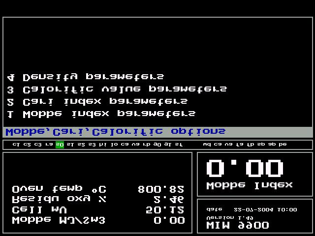
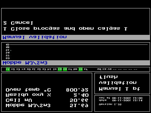
65 8.0 In operation 8.1 General When the analyser is started up it is controlled by the software settings and the readings on the internal display. This chapter will describe the structure and function of individual fields in the program. To start with we like to explain the different fields on the display. 8.2 How to read the display The main display can roughly be divided in three sections. The left top section is normally identified as the "Small display". Here are multiple parameters displayed such as cell millivoltage and residual Oxygen percentage. What exactly is displayed and in what order is programmable and will be explained further on in this manual. In the right hand top the analyser version, software version plus time and date are displayed, directly under here the measured value is displayed. Normally the Wobbe value is displayed, but it can be programmed to display for instance CARI. How this can be changed is explained further on in this manual. The lower half of the screen is divided into two charts where the measured values are displayed as a graph. Normally the Wobbe value and the residual Oxygen percentage are displayed but these can be changed to for instance CARI and SG values. In the middle of the screen a small strip with two digit codes is displayed. These codes are abbreviations of the in- and outputs. When a square green box is displayed around a code this indicates that the specific in- or output is active. The first 8 codes indicate internal actions within the analyser. The sequence of these is fixed. The 8th until 16th code are status indications of the alarm outputs. Please note; there are more output codes than shown on screen, which codes are displayed is depending on their routing to terminals (the screen follows the sequence of termination). The 8 codes to the right hand side indicate the status of input codes. Hereunder is a list with the abbreviations and their meaning. 8.3 Displayed Output abbreviations Status Signal Description code 1 c1 Digital out gas 1 Low calibration gas valve activated 2 c2 Digital out gas 2 Middle calibration gas valve activated 3 c3 Digital out gas 3 High calibration gas valve activated 4 ra Digital out Range 1 1st mixing chamber active 5 rb Digital out Range 2 2nd mixing chamber active (extended range only) 6 s0 Digital out Stream 0 Sample stream 1 active 7 s1 Digital out Stream 1 Sample stream 2 active (multi-stream only) 8 s2 Digital out Stream 2 Sample stream 3 active (multi-stream only) 9 s3 Digital out Stream 3 Sample stream 4 active (multi-stream only) 10 hi Digital out Wobbe High High Wobbe alarm output active 32 van 61
66
67 11 lo Digital out Wobbe Low Low Wobbe alarm output active 12 ca Digital out Calibrating Analyser in calibration active 13 va Digital out Validating Analyser in validation active 14 cf Digital out calibration Fault Calibration error 15 io Digital out In Operation Analyser in operation active 16 sf Digital out Fault Collective alarm active (system fault) 17 be Digital out Pressure Cal Pressure switch calibration bottle active (optional) 18 sp Digital out Pressure Sample Pressure switch sample line active (optional) 19 ap Digital out Pressure Air Pressure switch air line active (optional) 20 wd Digital out Watchdog Pulse Watchdog communication error active 21 g0 Gas 1 active Sample 1 being measured 22 g1 Gas 2 active Sample 2 being measured 23 v0 Gas 1 valid Sample 1 valid measurement 24 v1 Gas 2 valid Sample 2 valid measurement 8.4 Displayed Input abbreviations Status Signal Description code 1 wd Digital input Watchdog Watchdog communication error active (input PC) 2 ca Dig. in Calibration requirement External calibration command active 3 va Dig. in Validation requirement External validation command active 4 fa Flow alarm A Flow switch A active 5 fb Flow alarm B Flow switch B active 6 be Digital Input Pressure Calgas Pressure switch calibration bottle active (optional) 7 ap Digital Input Pressure air Pressure switch sample line active (optional) 8 sp Digital input Pressure sample Pressure switch air line active (optional) 9 ss Select stream External stream switch command On the bottom of the screen alarm messages are displayed. Whenever an alarm is activated the descriptive text, for instance "Wobbe too high", will be displayed on a flickering background. All alarms have to be acknowledged via the function "Reset alarm". If the cause of the alarm has been solved the message will disappear. If the alarm is acknowledged by "Reset alarm" but still current the message will remain to be displayed but its background will stop flickering. 8.5 The software menus From the main display lay-out that indicates measured values and status information one can enter the settings and parameters menus by pushing either < ESC > or < ENTER >. From the main screen one will end up in the "measuring menu" screen. The different menus hereunder can be reached by entering the number corresponding with the desired menu. At the end of this chapter an overview of the software tree for ease of navigation. 33 van 61
68
69 (8.5) < ESC > or < ENTER > Measuring Menu In the measuring menu the following sub-menus are available: 1. Change Parameters: Set-up of the global analyser parameters like oven temperature, measurement range, etc. 2. Display Options: Set-up of display options. 3. Calibration: Set-up of calibration parameters. 4. Reset Alarm: Reset alarm indication. 5. Login: Enter a password to enter protected menus. (8.5) 1. Global Settings Menu 1. Calibration: Set up of calibration settings. 2. Temperature: Set up of oven parameters. 3. Current Outputs A, B: Set up of current outputs. 4. Current Outputs C, D: Set up of current outputs. 5. Oxygen Parameters: Set up of oxygen parameters. 6. Wobbe, Cari, Calorific: Set up of Wobbe Index, Cari and Calorific parameters. 7. Other Options: Several other settings, for instance dual (or extended) range parameters. (8.5) 1.1 Calibration Settings 1. Automatic Calibration: Switched off when calibration valves are operated manually 2. Timed Calibration: Here the time to the first calibration can be set. 3. Timed Calibration Method: This field offers two options; Weekly and Repeat. When Weekly is chosen the automatic calibration schedule can be programmed to a schedule that is repeated weekly. Separate calibration times can be entered per day of the week. When Repeat is chosen the automatic calibration schedule can be entered for one fixed point in time and a repeat interval is entered. For details please refer to Calibration schedule. 4. Remote Calibration: When "on" is selected, it is possible to start external calibration or validation, by activating an input contact. 5. Cal Start Delay: Delay between closing the calibration contact and the actual start of calibration. 6. Cal Gas Switch Time: Stabilisation time is entered, which is needed after switching the solenoid valves. 7. Calib Error Detect: Switch off/on calibration fault alarm. 8. Calib Error Perc.: Deviation percentage slope or offset value activation alarm. 34 van 61
70
71 (8.5) 1.2 Current Outputs A, B 1. Output A Signal: The dimension for output A can be chosen, options are; OFF / Cari / Wobbe / Oxy / Calorif / 25% / 50% / 75% / High / SG. 2. 0/4 ma Value: Enter the lowest value of the measurement range ma Value: Enter the highest value of the measurement range. 4. During Cal: Select display method during calibration for Output A, options are; Hold / Track / 0-4mA. 5. Output B Signal: The dimension for output B can be chosen, options are; OFF / Cari / Wobbe / Oxy / Calorif / 25% / 50% / 75% / High / SG. 6. 0/4 ma Value: This is the lowest value of the measurement range ma Value: This is the highest value of the measurement range. 8. During Cal: Select display method during calibration for Output B, options are; Hold / Track / 0-4mA. (8.5) 1.3 Current Outputs C, D 1. Output C Signal: The dimension for output C can be chosen, options are; OFF / Cari / Wobbe / Oxy / Calorif / 25% / 50% / 75% / High / SG. 2. 0/4 ma Value: Enter the lowest value of the measurement range ma Value: Enter the highest value of the measurement range. 4. During Cal: Select display method during calibration for Output A, options are; Hold / Track / 0-4mA. 5. Output D Signal: The dimension for output D can be chosen, options are; OFF / Cari / Wobbe / Oxy / Calorif / 25% / 50% / 75% / High / SG. 6. 0/4 ma Value: Enter the lowest value of the measurement range ma Value: Enter the highest value of the measurement range. 8. During Cal: Select display method during calibration for Output B, options are; Hold / Track / 0-4mA. (8.5) 1.4 Oxygen Parameters 1. Oxygen Low Alarm: Alarm level for low cell voltage 2. Oxygen High Alarm: Alarm level for high cell voltage 3. Z Factor Normal: Factor for Advanced averages "Advanced averages"; The measurement signal shows a noise. To reduce noise as much as possible, the signal will be filtered by an algorithm; the advanced averages. A higher Z-factor will give more noise suppression and the signal will be more stable. A lower Z-factor will give less noise suppression but a faster response. 4. Z Factor Calibration: See 3 Z factor normal. 5. Oxy Cal. Offset: Correction for difference in the actual 02 signal and reproduced value at a low mv voltage. (<5 mv) 6. Oxy Slope: Correction for difference in the actual versus the reproduced oxygen content at a high mv voltage (> 80mV) 35 van 61

72
73 (8.5) 1.5 Wobbe, Cari, Calorific Options 1. Wobbe Index Parameters: Set-up of Wobbe Index Measurement. 2. Cari Index Parameters: Set-up of CARI Index Measurement. 3. Calorific Value Parameters: Set-up of Calorific value parameters. (8.5) Wobbe Index Parameters 1. Wobbe Dimension: The following units can be selected: MJ/ Nm3, Kcal/ Nm3, BTU/SCF, MJ/Sm3. 2. Wobbe C0 (offset): Intercept low range calibration. 3. Wobbe C1 (span): Span coefficient for low range calibration. 4. Wobbe HR C0 (offset): Intercept high range calibration (Extended range only WIM 9902) 5. Wobbe HR C1 (span): Span coefficient for high range calibration (Extended range only WIM 9902) 6. Wobbe High alarm: High alarm level for Wobbe Index. 7. Wobbe Low alarm: Low alarm level for Wobbe Index. 8. Wobbe Chart Step-size: Field where step-size (chart scale) for Wobbe chart on display can be entered 9. Wobbe Chart Step-count: Field where no off steps for Wobbe chart on display can be entered (8.5) CARI Index Parameters 1. Cari C0 (Offset): Intercept low range calibration. 2. Cari C1 (Slope): Slope coefficient for low range calibration. 3. Cari HR C0 (Offset): Intercept high range calibration.(extended range only WIM 9902). 4. Cari HR C1 (Slope): Slope coefficient for high range calibration (Extended range only WIM 9902). 5. Cari High Alarm: High alarm level for CARI index. 6. Cari Low Alarm: Low alarm level for CARI index. 36 van 61
74
75 (8.5) Calorific Value Parameters 1. Spec Grav Input: Enable or disable current input from specific gravity meter. 2. Low Voltage: Lowest current value from specific gravity meter. 3. Low SG: Enter known specific gravity value for low calibration gas. 4. High Voltage: Highest current value from specific gravity meter. 5. High SG: Enter known specific gravity value for high calibration gas. 6. SG Low Alarm: Enter low alarm level for specific gravity. 7. SG High Alarm: Enter high alarm level for specific gravity 8. Calor. dimension The following units can be selected: MJ/Nm3, kcal/nm3, BTU/SCF, MJ/Sm3, kj/kg, MJ/kg (8.5) Density Parameters 1. Density dimension: The following units can be selected: kg/nm3, lbs/cf 2. Gr chart stepsize Field where step-size (chart scale) for Density chart on display can be entered 3. Gr chart stepcount: Field where the no of steps for Density chart on display can be entered 4. Process pressure: Enter the pressure the analysers sample pressure is set to. Thus enable unit to calculate a proper Density output signal under standard conditions Both H2 and CO have a non linearity in the relation Wobbe Index - residual Oxygen after combustion. Because of this effect the compensation formula Value = Value + (A:SG) + B is introduced where the A and B are correction factors. The determination of these fixed compensation factors is to be done on a case to case basis by Hobré instruments. 5. H2 factor A: Correction factor A for compensation of non linear components 6. H2 factor B: Correction factor B for compensation of non linear components (8.5) 1.6 Other Options 1. Values Display Layout: Set-up of values layout on display. 2. Temperature: Set-up of oven parameters. 3. Dual Range Parameters Set up for Extended Range parameters (9902 only). 4. Multi-Stream Parameters Set up for Multiple sample streams 37 van 61

76
77 (8.5) Values Display Layout The top left-hand display area (normally called Small display ) can display several parameters on the 6 text lines available. One can choose from the following parameters: None / Wobbe / Cari / Oxy mv / Oxy % / Oven Temp / SG / Calorif / Board Temp / Board Po / SG Voltage. Via this screen one can built 4 different sets (of 6 parameter lines) which can be easily switched between. Please refer to Small display mode for details on how to switch between the screens. 1. Mode Normal : Field to adapt first parameter set on small display. 2. Mode Values : Field to adapt second parameter set on small display 3. Mode Others : Field to adapt third parameter set on small display 4. Mode Calibrating : Field to adapt fourth parameter set on small display. (8.5) Mode Normal Layout 1. Normal 0: Select parameter to be displayed on first text line. 2. Normal 1: Select parameter to be displayed on second text line. 3. Normal 2: Select parameter to be displayed on third text line. 4. Normal 3: Select parameter to be displayed on fourth text line. 5. Normal 4: Select parameter to be displayed on fifth text line. 6. Normal 5: Select parameter to be displayed on sixth text line. (8.5) Mode Values Layout Identical as Mode normal layout (8.5) Mode Others Layout Identical as Mode normal layout (8.5) Mode Calibrating Layout Identical as Mode normal layout (8.5) Temperature Settings 1. Oven Temp Required: Temperature to be equal to the oven temp set point. The value is used in the cell mv to oxygen calculation. 2. Oven Temp Low Alarm: Low temperature alarm level. 3. Oven Temp High Alarm: High temperature alarm level. 4. Oven Temp Z Factor: Averaging factor, used in algorithm to minimise noise. 5. Oven Temp Adjustment: Can be switched ON/OFF. When switched on the actual oven temperature is used in the calculation, Normally off. 6. Warm-up Delay: No reproduction measurement signal during the initial heating period. 7. Operation Delay: No reproduction measurement signal during the delay period. 8. Oven Cal Offset: Value to correct the offset between the regulated temperature and the displayed temperature. 9. Oven Cal Slope: Value to correct the difference in span between the regulated temperature and the displayed temperature. 38 van 61
78
79 (8.5) Dual Range Parameters 1. Enable Dual Range System: When a dual range system is physically present, this. value is set to on. 2. Oxygen Flip Above: This voltage sets the change pint from low to high range. It can be set manually, but it is also calculated automatically during a calibration. 3. Oxygen Flop Below: This voltage sets the change pint from high to low range. It can be set manually, but it is also calculated automatically during a calibration. 4. Range Hysteresis +mv: This voltage is added to the medium calibration gas mv signal, during a calibration when the low range is selected. 5. Range Hysteresis +mv: This voltage is subtracted to the medium calibration gas mv signal, during a calibration when the high range is selected. 6. Range Switch Hold: This value determines the stabilisation time after a range change. During the stabilisation time, the output signal will be frozen. Range switching will not be initialised. (8.5) Multi-stream Parameters The analyser can switch between multiple sample streams. Please note that the composition of the streams must be equal or near equal since the analyser utilises one set of calibration parameters for all measured lines. After a stream switch action the analyser will transmit a live signal for the measured stream. The signals for other streams will be frozen and permanently transmitted on the last known value. There are 4 different operation modes: "Off" : All multi-stream features de-activated "Remote" : Stream switching activated by external input command "Continue" : The analyser will continuously measure the stream selected "Timer" : The analyser will measure each stream for the time period entered Note: When the analyser is set to one of the 4 operation modes switch commands from other modes will be ignored. For instance: If the analyser is set to "Timer" an external switch command via the inputs will be ignored. 1. Multi-stream mode: Select the operation mode for stream switching 2. Number of streams: Set this field to the number of streams connected to the analyser 3. Continuous stream: Set to the desired stream to be measured continuously 4. Measuring time stream 0: Enter the time period the analyser is to continuously measure stream 0 5. Measuring time stream 1: Enter the time period the analyser is to continuously measure stream 1 6. Switch delay: Enter stabilisation period after stream switch command. During this fixed time period the analyser will remain the analogue signal outputs on the last known value and delay the actuation of the stream valid contact. 39 van 61
80
81 (8.5) 2. Display Options 1. Large Display Mode: Parameter shown in the large display can be selected here. 2. Small Display Mode: Parameters shown in the upper left screen can be selected here. 3. Top Chart Mode: Parameter shown in the top chart can be selected here. 4. Bottom Chart Mode: Parameter shown in the bottom chart can be selected here. 40 van 61

82
83 (8.5) 3. Calibration 1. Edit Cal Gas Parameters: In this selection the calibration gas definitions are entered. 2. Calibration Schedule: Here a weekly calibration schedule is established. 3. Start Calibration: Start an automatic or a manual calibration. 4. Start Validation: Start an automatic or a manual validation. (8.5) 3.1 Edit Cal Gas Parameters 1. Cal Gas 1 Wobbe: Wobbe index value low calibration gas. 2. Cal Gas 1 Cari: Cari value low calibration gas. 3. Cal Gas 1 SG: Specific gravity value low calibration gas. 4. Cal Gas 2 Wobbe: Wobbe index value medium calibration gas. 5. Cal Gas 2 Cari: Cari value medium calibration gas. 6. Cal Gas 2 SG: Specific gravity value high calibration gas. 7. Cal Gas 3 Wobbe: Wobbe index value high calibration gas. 8. Cal Gas 3 Cari: Cari value high calibration gas. (8.5) 3.2 Calibration Schedule (Weekly) This screen appears when Timed calibration method is set to Weekly. This screen reproduces a schedule of the established calibration or validation times over a week. C stands for calibration and V stands for validation. Adaptations are possible by choosing a day. For example when you press number 4, the schedule for Thursday will appear. Changes can be done by simply typing in the required time. By choosing VAL, slope and offset will not be adjusted ( V will appear behind the point of time in the main menu). 41 van 61
84
85 (8.5) 3.2 Calibration Schedule (Repeat) This screen appears when the Timed calibration method is set to Repeat. Via this screen one can enter a point in time for calibration and a repeat interval. (8.5) 3.3 Start Calibration 1. Start Automatic Calibration: An automatic calibration cycle is going to be started; intercept C0 and the slope C1 will be calculated. 2. Manual One-Point Calibration: Only one calibration gas is used for manual calibration, only C0 will be adjusted. 3. Manual Two-Point Calibration: Two calibration gasses are being used during the manual calibration. 4. Manual Dual-Range Calibration: Three calibration gasses are being used for manual calibration (Extended range only WIM 9902). If chosen for a manual calibration (Figure Manual one point Calibration), the instructions for the operator will appear on the display. Opening or closing the valves must only be done when the measurement value is stable. 42 van 61
86
ANNEX AMENDMENTS TO THE INTERNATIONAL CODE FOR FIRE SAFETY SYSTEMS (FSS CODE) CHAPTER 15 INERT GAS SYSTEMS
 CHAPTER 15 INERT GAS SYSTEMS") Annex 3, page 2 ANNEX AMENDMENTS TO THE INTERNATIONAL CODE FOR FIRE SAFETY SYSTEMS (FSS CODE) CHAPTER 15 INERT GAS SYSTEMS The text of existing chapter 15 is replaced by the following: "1 Application This
Annex 3, page 2 ANNEX AMENDMENTS TO THE INTERNATIONAL CODE FOR FIRE SAFETY SYSTEMS (FSS CODE) CHAPTER 15 INERT GAS SYSTEMS The text of existing chapter 15 is replaced by the following: "1 Application This
OXY Integral. INTERCON ENTERPRISES INC Tel: Fax: Internet:
 OXY Integral INTERCON ENTERPRISES INC Tel: 800 665 6655 Fax: 604 946 5340 E-Mail: sales@intercononline.com Internet: www.intercononline.com Manual Integral 2006 1 INDEX 2-3 PREFACE 4 INTRODUCTION 5 Principle
Micro Motion 3098 Gas Specific Gravity Meter
 Product Data Sheet PS-001188, Rev. B April 2009 Micro Motion 3098 Gas Specific Gravity Meter Micro Motion density and concentration meters are built to tackle the most demanding process and fiscal applications.
Two-Wire In Situ Oxygen Analyzer (550 to 1400 C)
") Product Data Sheet PDS 106-581.A01 March, 2004 Model 5081FG Two-Wire In Situ Oxygen Analyzer (550 to 1400 C) Intrinsically safe: - CENELEC EEx ia IIC - Class I Div. I Gr. B, C, D (pending) Operates at
Product Data Sheet PDS 106-581.A01 March, 2004 Model 5081FG Two-Wire In Situ Oxygen Analyzer (550 to 1400 C) Intrinsically safe: - CENELEC EEx ia IIC - Class I Div. I Gr. B, C, D (pending) Operates at
Technical Data Sheet MF010-O-LC
 Technical Data Sheet MF010-O-LC - 1 - 1. Properties The oxygen measuring system MF010-O-LC determines the oxygen content in gas mixtures up to a temperature of 250 C. It is particularly suitable for the
Spirax Compact FREME Flash Recovery Energy Management Equipment
 IM-UK-cFREME UK Issue 1 Spirax Compact FREME Flash Recovery Energy Management Equipment Installation and Maintenance Instructions 1. Safety information 2. General product information 3. Installation 4.
Best Practice Guide, Servomex 2700
 For full installations details refer to the. Best Practice Guide, Servomex 2700 Mounting: General Guidelines: Servomex 2700 Control Units and air supplies (utilities units) should, ideally, be mounted
Pressure Automated Calibration Equipment
 GE Measurement & control Pressure Automated Calibration Equipment Safety Instructions and User Guide - K0447 PACE5000 PACE6000 K0447 Issue No. 9 1 10 1 PACE5000 1 2 3 4 5 PACE6000 2 6 7 8 3 4 5 6 7 8 9
This test shall be carried out on all vehicles equipped with open type traction batteries.
 5.4. Determination of hydrogen emissions page 1 RESS-6-15 5.4.1. This test shall be carried out on all vehicles equipped with open type traction batteries. 5.4.2. The test shall be conducted following
Installation, operating and maintenance Instructions for Seemag bypass level indicator
 Issue: S Date: 05-09-14 Type G35 General information The Seetru bypass magnetic level indicator, abbreviate SEEMAG, serves to show the filling level of fluids in tanks, basins, tubes etc. The Seemag operates
MODEL GT820 OXYGEN SENSOR
 INSTRUCTION MANUAL MODEL GT820 OXYGEN SENSOR 70046 The information and technical data disclosed by this document may be used and disseminated only for the purposes and to the extent specifically authorized
Transmitter CS 21 Operation Manual
 Transmitter CS 21 Operation Manual Content Page For your Safety 3 General Description 3 Detection Principle 4 Operational Notes 4 Design 4 Mounting Position of CS21 5 Mounting 6 Installation of Electrical
GM Series Dual-Block Multi-Function Gas Control Valves
 Installation Sheets Manual 121 Gas Combustion Combination Controls and Systems Section G Technical Bulletin GM Issue Date 0297 GM Series Dual-Block Multi-Function Gas Control Valves Figure 1: GM Series
Columbus Instruments
 0215-003M Portable O 2 /CO 2 /CH 4 Meter User s Manual Columbus Instruments 950 NORTH HAGUE AVENUE TEL:(614) 276-0861 COLUMBUS, OHIO 43204, USA FAX:(614) 276-0529 1 www.colinst.com TOLL FREE 1-800-669-5011
Electro-Pneumatic Converter YT-940 SERIES
 Electro-Pneumatic Converter YT-940 SERIES PRODUCT MANUAL VERSION 1.00 Contents 1. Introduction 3 1.1 General information for the users. 3 1.2 Manufacturer Warranty 3 1.3 Explosion Proof Warning. 4 2. Product
Automatic Isokinetic Sampler. ST5 Evo
 Automatic Isokinetic Sampler ST5 Evo Automatic Isokinetic Sampler ST5 Evo Moreover, in case of pump failure, the CU can work with a spare Dado PU unit or with any pump capable to supply the needed flowrate,
MEGAS 2.0. Gas analysis with direct C-Level Calculation and Bus-Connection. Data sheet
 Data sheet MEGAS 2.0 Gas analysis with direct C-Level Calculation and Bus-Connection Mesa Industrie-Elektronik GmbH Neckarstraße 19, D-45768 Marl info@mesa-gmbh.de +49 (0) 2365-97 45 1-0 +49 (0) 2365-97
The Ins and Outs of I/P Transducers
 The Ins and Outs of I/P Transducers By Mark B. Levine, ControlAir Inc. General description I/P transducers are versatile instruments that use an electrical control signal to proportionally regulate gas
JOLLY2. Installation user s manual. 6 different operating modes selectable. version 3.3. DATA TO BE FILLED OUT BY THE INSTALLER (Page 1)
") ENGLISH ENGLISH ENGLISH ENGLISH Installation user s manual Warning! electrical scheme modified JANUARY 2005 version 3.3 JOLLY2 DATA TO BE FILLED OUT BY THE INSTALLER (Page 1) 6 different operating modes
ENGLISH ENGLISH ENGLISH ENGLISH Installation user s manual Warning! electrical scheme modified JANUARY 2005 version 3.3 JOLLY2 DATA TO BE FILLED OUT BY THE INSTALLER (Page 1) 6 different operating modes
DK46 - DK800 Supplementary instructions
 DK46 - DK800 Supplementary instructions Variable area flowmeter Device category II2G with electrical internals Additional Ex manual KROHNE CONTENTS DK46 - DK800 1 Safety instructions 3 1.1 General... 3
BUBBLER CONTROL SYSTEM
 BUBBLER CONTROL SYSTEM Description: The HDBCS is a fully automatic bubbler system, which does liquid level measurements in water and wastewater applications. It is a dual air compressor system with, air
TWC Services, Inc. Structured On-The-Job Training for JT- 1, 2, 3
 TWC Services, Inc. Structured On-The-Job Training for JT- 1, 2, 3 The following tasks parallel the Jr. Tech (JT-1, 2, 3) description and development plan and use the Refrigeration and Air conditioning
L 100. Bubble-Tube Level System. Installation, Operation and Maintenance Instructions
 L 100 Bubble-Tube Level System Installation, Operation and Maintenance Instructions Figure 1 Contents Section Description Page 1.0 Introduction 2 2.0 Specifications 3 3.0 Installation 3 4.0 Warranty 6
XMO2. Panametrics Smart Oxygen Analyzer. Applications. Features. bhge.com. An oxygen transmitter for use in:
 XMO2 Panametrics Smart Oxygen Analyzer Applications An oxygen transmitter for use in: Inerting/blanketing liquid storage tanks Reactor feed gases Centrifuge gases Catalyst regeneration Solvent recovery
ACCURATE PRESSURE MEASUREMENT FOR STEAM TURBINE PERFORMANCE TESTING
 ACCURATE PRESSURE MEASUREMENT FOR STEAM TURBINE PERFORMANCE TESTING Blair Chalpin Charles A. Matthews Mechanical Design Engineer Product Support Manager Scanivalve Corp Scanivalve Corp Liberty Lake, WA
DF-550E PROCESS ANALYSERS APPLICATIONS FEATURES
 PROCESS ANALYSERS DF-550E The DF-550E Nano Trace oxygen analyser is a Coulometric sensor based analyser designed to measure oxygen as a contaminant at ultra trace levels in ultra high purity electronic
CENTRAL GAS SUPPLY SYSTEMS : CYLINDER BATTERIES AND HIGH PRESSURE HOSES
 P0170E-1.DOCX/08.16/MG CENTRAL GAS SUPPLY SYSTEMS : CYLINDER BATTERIES AND HIGH PRESSURE HOSES With a Central Gas Supply System, individual work places or gas take-off stations are supplied with gas through
Installation, Operation and Maintenance Instructions for Electronically Controlled Pressurisation Units
 Installation, Operation and Maintenance Instructions for Electronically Controlled Pressurisation Units Models: EPS Single Pump EPT Twin Pump EPS-HP EPT-HP Single Pump High Pressure Twin Pump High Pressure
DF-310E PROCESS ANALYSERS APPLICATIONS FEATURES
 PROCESS ANALYSERS DF-310E The DF-310E is a Coulometric sensor based oxygen analyzer designed to measure trace and percent level oxygen in pure and multi-gas backgrounds for process and quality control
SCOPE OF THIS GUIDE STARTING-UP. 1 Check mini CORI-FLOW functional properties
 Quick Installation Guide Doc nr.: 9.17.052H Date: 10-12-2015 SCOPE OF THIS GUIDE mini CORI-FLOW instruments are highly accurate instruments for measuring and controlling the mass flow rate of liquids and/or
BGA244 Binary Gas Analyzer
 Quick Start Guide Revision 1.0 Certification Warranty Service certifies that this product met its published specification at the time of shipment. This product is warranted against defects in materials
Inert Air (N2) Systems Manual
 Systems Manual") INSTRUCTION MANUAL Inert Air (N2) Systems Manual N2-MANUAL 2.10 READ AND UNDERSTAND THIS MANUAL PRIOR TO OPERATING OR SERVICING THIS PRODUCT. GENERAL INFORMATION Positive pressure nitrogen gas pressurizing
INSTRUCTION MANUAL Inert Air (N2) Systems Manual N2-MANUAL 2.10 READ AND UNDERSTAND THIS MANUAL PRIOR TO OPERATING OR SERVICING THIS PRODUCT. GENERAL INFORMATION Positive pressure nitrogen gas pressurizing
MP15 Jockey Pump Controller
 Setup and Operating Instructions MP15 Jockey Pump Controller This manual provides general information, installation, operation, maintenance, and system setup information for Metron Model MP15 Jockey Pump
Modulating Valves for Atmospheric, Infrared, and Direct Fired Burners
 BULLETIN MT2035-07/05 Modulating Valves for Atmospheric, Infrared, and Direct Fired Burners M/MR Series M411, M511, M611 M420, M520, M620, MR410, MR510, MR610 MR212D, MR212E, MR212G and MR212J (Flanged),
PRODUCT CONFORMITY CERTIFICATE
 PRODUCT CONFORMITY CERTIFICATE This is to certify that the Endura AZ20 / AZ30 measuring system Manufactured by: ABB Ltd Oldends Lane Stonehouse Gloucestershire GL10 3TA has been assessed by Sira Certification
Supplementary Operator s Manual 42/24-14 EN Rev. 3
 Advance Optima Continuous Gas Analyzers AO2000 Series with Uras26, Magnos206, Caldos25, Caldos27 Designed per Category 3G for Measurement of Flammable Gases ( Safety Concept ) and Non-flammable Gases Supplementary
TA10A and TA10P Steam Tracing Temperature Control Valves Installation and Maintenance Instructions
 3500032/2 IM-P350-02 CH Issue 2 TA10A and TA10P Steam Tracing Temperature Control Valves Installation and Maintenance Instructions 1. Safety information 2. General product information 3. Installation 4.
MASS-STREAM TM Instruction Manual. D-6200 Analog Mass Flow Meters / Controllers
 MASS-STREAM TM Instruction Manual D-6200 Analog Mass Flow Meters / Controllers Doc. No.: 9.17.112A Date: 17-03-2017 ATTENTION Before installing and operating the instrument it is strongly recommended that
Quick Installation Guide Doc nr.: C Date:
 Quick Installation Guide Doc nr.: 9.17.093C Date: 13-05-2016 SCOPE OF THIS GUIDE mini CORI-FLOW instruments are highly accurate instruments for measuring and controlling the mass flow rate of liquids and/or
AMT-Ex Dewpoint Transmitter
 AMT-Ex Dewpoint Transmitter Instruction Manual Alpha Moisture Systems Alpha House 96 City Road Bradford BD8 8ES England Tel: +44 1274 733100 Fax: +44 1274 733200 email: mail@amsytems.co.uk web: www.amsystems.co.uk
J. David Hailey Ph.D. Vice President, Business Development COSA Xentaur 7125 North Loop East Houston, TX 77028
 METHODOLOGY FOR RESIDUAL OXYGEN CALORIMETRY J. David Hailey Ph.D. Vice President, Business Development COSA Xentaur 7125 North Loop East Houston, TX 77028 KEYWORDS Combustion Air Requirement Index (CARI)
Intelligent SUNTEX DC-5310(RS) Dissolved Oxygen Transmitter
 Dissolved Oxygen Transmitter") Intelligent SUNTEX DC-5310(RS) Dissolved Oxygen Transmitter Overview C % ppm 4~20mA Analog Output ppb Power Supply 100~240 VAC mg/l Dimensions 96 x 96 x 132mm RS-485 Digital Output (for DC-5310-RS only)
Intelligent SUNTEX DC-5310(RS) Dissolved Oxygen Transmitter Overview C % ppm 4~20mA Analog Output ppb Power Supply 100~240 VAC mg/l Dimensions 96 x 96 x 132mm RS-485 Digital Output (for DC-5310-RS only)
DPC-30 DPC-100. Reference Manual
 DPC-30 DPC-100 Reference Manual 1. Introduction 1.1 Description The Martel DPC Digital Pneumatic Calibrator improves upon traditional dial gauge pneumatic calibrators. The Martel DPC improves accuracy,
I/P Transducer Positioner Module
 I/P Transducer Positioner Module VRC P/N: 7958032 Installation, Operation and Maintenance Instructions 2.09 [53.1] 1.30 [32.9] 2.97 [75.5] 0.78 [19.8] 0.18 [4.4] 1.42 [36.1] n.18 MOUNTING HOLES (2) PLACES
High Pressure Chem-SCAN Operating Manual
 GAS INLET VALVES REACTIVE GAS PRESSURE RELIEF VALVE INERT GAS VENT VENT VALVE REACTOR INLET VALVES PRESSURE TRANSDUCERS REACTORS STIRRER & THERMOWELL HEATING JACKET STIRRER MOTORS High Pressure Chem-SCAN
Installation and Operation Manual
 Manual Static pressure transducer with controller Differential static pressure transducer with analog output and optional PI control mode Large diaphragm element with differential transformer Transducer
MASS FLOW SYSTEMS MASS FLOW MEASURING, CONTROLLING AND BLENDING SYSTEMS
 MASS FLOW SYSTEMS MASS FLOW MEASURING, CONTROLLING AND BLENDING SYSTEMS Using state-of-the-art measuring and microprocessor technologies, Advanced has assembled a series of systems which can measure mass
LTB013EN. Operating Instruction Trimod Besta Level Switch types XA 5, XB 5 for use in potentially explosive atmospheres acc.
 LTB013EN Operating Instruction Trimod Besta Level Switch types XA 5, XB 5 for use in potentially explosive atmospheres acc. to IECEx scheme Subject to technical modification Bachofen AG Ackerstrasse 42
CABLE ENTRIES IN HAZARDOUS AREAS CORRECT SELECTION, INSTALLATION AND MAINTENANCE
 CABLE ENTRIES IN HAZARDOUS AREAS CORRECT SELECTION, INSTALLATION AND MAINTENANCE Compiled by: Arthur Cameron NOT SO CORRECT SELECTION AND INSTALLATION OF CABLE GLANDS AND JUNCTION BOXES IN HAZARDOUS AREAS
Instruction Manual Dräger MSI P7 and MSI P7 plus
 Dräger MSI GmbH Rohrstraße 32 58093 Hagen Tel.: +49-2331 / 9584-0 Fax: +49-2331 / 9584-29 e-mail: info@draeger-msi.de D 923; Edition 2011-01-01 Content 1. General Hints Page 4 2. The Instrument 2.1 Front
English. Introduction. Safety Instructions. All Products. Inspection and Maintenance Schedules. Parts Ordering. Specifications WARNING WARNING
 Contents All Products... Gb-1 Control Valves... Gb-2 Control Valve Actuators... Gb-3 Regulators... Gb-3 Relief Valves... Gb-4 Instruments, Switches, and Accessories... Gb-4 Products Covered by Battery
Appendix D: SOP of INNOVA 1412 Photoacoustic Multi-Gas Monitor. Description and Principle of Operation
 Page 1 of 19 : SOP of INNOVA 1412 Photoacoustic Multi-Gas Monitor Description and Principle of Operation The photoacoustic multi-gas monitor (INNOVA 1412, Innova AirTech Instruments, Denmark) is a highly
UL Listed GM-20/25 and GM-40/45 Series Dual-block Multi-function Gas Control Valves
 Installation Sheets Manual 121 Gas Combustion Combination Controls and Systems Section G Technical Bulletin GM-20/25 GM-40/45 Issue Date 1298 UL Listed GM-20/25 and GM-40/45 Series Dual-block Multi-function
ACV-10 Automatic Control Valve
 ACV-10 Automatic Control Valve Installation, Operation & Maintenance General: The Archer Instruments ACV-10 is a precision automatic feed rate control valve for use in vacuum systems feeding Chlorine,
Operating instructions Safety Rope Emergency Stop Switches ZB0052 / ZB0053 ZB0072 / ZB0073
 Operating instructions Safety Rope Emergency Stop Switches UK ZB0052 / ZB0053 ZB0072 / ZB0073 7390878 / 02 03 / 2011 Contents 1 Safety instructions...3 2 Installation / set-up...4 2.1 Applications...4
VERTICAL AIR COMPRESSORS
 VERTICAL AIR COMPRESSORS MODEL NO: VE11C150, VE15C150, VE18C150 PART NO: 2226005, 2226000, 2226015 OPERATION & MAINTENANCE INSTRUCTIONS LS0615 INTRODUCTION Thank you for purchasing this CLARKE Vertical
OSAT Series. Intrinsically Safe Infrared Temperature Sensor Operator's Guide
 OSAT Series Intrinsically Safe Infrared Temperature Sensor Operator's Guide Issue L Jan 2017 Introduction OSAT Series intrinsically safe non-contact infrared temperature sensors measure the temperature
BUBBLER CONTROL SYSTEM
 BUBBLER CONTROL SYSTEM Description: The LDBCS is a fully automatic bubbler system, which does liquid level measurements in water and wastewater applications. It is a dual air compressor system with, air
Manual Actuated Boiler Blowdown Valves
 Manual Actuated Boiler Blowdown Valves Installation and Maintenance Instructions 1. Safety information 2. General product information 3. Installation 4. Operation 5. Maintenance 6. Spare parts p.1 1. Safety
User Manual. Quantos Automated Dosing Liquid Module
 User Manual Liquid Module 1 Safety Information 1.1 Definition of warnings and symbols Signal Words WARNING for a hazardous situation with medium risk, possibly resulting in severe injuries or death if
PURGEX X Purge Controller E Version. User s Manual
 PURGEX X Purge Controller E Version User s Manual This page intentionally left blank Information in this document is subject to change without notice. All terms mentioned in this manual that are known
QuickHeat TM Packaged Heat Exchanger Solutions
 4831999/1 IM-P483-03 CH Issue 1 QuickHeat TM Packaged Heat Exchanger Solutions Installation and Maintenance Instructions 1. Safety information 2. General product information 3. Installation 4. Commissioning
CORESTA RECOMMENDED METHOD N 6
 CORESTA RECOMMENDED METHOD N 6 DETERMINATION OF VENTILATION DEFINITIONS AND MEASUREMENT PRINCIPLES (2015 Revision September 2016) 1. SCOPE This CORESTA Recommended Method specifies a method for the determination
VERTICAL AIR COMPRESSORS
 VERTICAL AIR COMPRESSORS MODEL NO: VE15C150, VE18C150, VE25C150 PART NO: 2226010, 2226020, 2226025 OPERATION & MAINTENANCE INSTRUCTIONS LS0715 INTRODUCTION Thank you for purchasing this CLARKE Vertical
KMW3000C. User Manual. Water Chiller for Xcalibur and Gemini systems. Version 1.6, September 2010
 KMW3000C Water Chiller for Xcalibur and Gemini systems User Manual Version 1.6, September 2010 Agilent Technologies XRD Products 10 Mead Road, Yarnton, Oxfordshire. OX5 1QU, UK Tel: +44 (0)1865 291600
Two-Wire In Situ Oxygen Analyzer (550 to 1400 C)
") Product Data Sheet PDS 106-581.A01 September, 2007 Model 5081FG Two-Wire In Situ Oxygen Analyzer (550 to 1400 C) Intrinsically safe: ATEX, Zone 1, EEx ia IIC T4 Class I, Div. I, Gr. A, B, C, D T4 Operates
Product Data Sheet PDS 106-581.A01 September, 2007 Model 5081FG Two-Wire In Situ Oxygen Analyzer (550 to 1400 C) Intrinsically safe: ATEX, Zone 1, EEx ia IIC T4 Class I, Div. I, Gr. A, B, C, D T4 Operates
How to specify a product. Process Sensors and Mechanical Instruments
 How to specify a product Process Sensors and Mechanical Instruments Keep the overview. Here is some guideline information on how to specify our products. Intended as supplementary help to specification
Autocalibration Systems For In Situ Oxygen Analyzers
 Product Data Sheet PDS 106-340AC SPS 4000, IMPS 4000, and MPS 3000 January, 1999 Autocalibration Systems For In Situ Oxygen Analyzers Cost-effective autocalibration systems for installations ranging from
Zirconia Oxygen Sensors. Model 1230 Series
 Zirconia Oxygen Sensors Model 1230 Series March 2003 USING THIS MANUAL CAUTION 1 The probe or sensor heater is supplied with mains voltage. This supply has electrical shock danger to maintenance personnel.
Operating Instructions
 Operating Instructions Light-metal Ex d enclosures / flameproof enclosure > 8265/0 Empty enclosure > 8265/4 Control panel, integrated in Ex e enclosure > 8265/5 Control panel Table of Contents 1 Table
Dri-Line Mk3 Monnier Compressed Air Drain Trap
 5044050/2 IM-P504-24 CH Issue 2 Dri-Line Mk3 Monnier Compressed Air Drain Trap Installation and Maintenance Instructions 1. Safety information 2. General product information 3. Installation and Operation
The HumiSys. RH Generator. Operation. Applications. Designed, built, and supported by InstruQuest Inc.
 The HumiSys RH Generator Designed, built, and supported by InstruQuest Inc. Versatile Relative Humidity Generation and Multi-Sensor System The new HumiSys with single or dual RH probes capabilities is
MANUAL DIRECT PURGE OPTION. UNION Instruments GmbH CWD2005 PLUS. General information, safety standards and regulations for direct purge option
 MANUAL DIRECT PURGE OPTION UNION Instruments GmbH CWD2005 PLUS General information, safety standards and regulations for direct purge option Version: V1.00 Stand: 24.03.2010 Union Instruments GmbH Zeppelinstr.
METROTEC GSM. Type GSM. Oxygen measurement and control unit. *** Version 1.6 ***
 Systems for oxygen measurement GSM Oxygen measurement and control unit Type GSM *** Version 1.6 *** Declaration of Conformity for Oxygen measurement and control unit GSM This device has been designed for
Gas Network Craftsperson
 Gas Network Craftsperson Unit EIAU06 Maintaining Instrumentation and Control Equipment Circuits This assessment specification has been developed as part of the network maintenance craftsperson standard
MODEL NUMBER: PSI AIR SOURCE KIT 200 PSI Compressor on 2.0 Gallon 200 PSI Air Tank
 IMPORTANT SAFETY INSTRUCTIONS CAUTION - To reduce risk of electrical shock or Electrocution: MODEL NUMBER: 20008 200 PSI AIR SOURCE KIT 200 PSI Compressor on 2.0 Gallon 200 PSI Air Tank IMPORTANT: It is
The Discussion of this exercise covers the following points:
 Exercise 5-3 Wet Reference Leg EXERCISE OBJECTIVE Learn to measure the level in a vessel using a wet reference leg. DISCUSSION OUTLINE The Discussion of this exercise covers the following points: Measuring
Intrinsically safe solenoid valves on/off controls - ATEX certification
 www.atos.com Table E130-17/E Intrinsically safe solenoid valves on/off controls - ATEX certification valve body valve spool intrinsically safe solenoid electrical connector manual override DHW-0611/WP/6
Hot extractive multi-channel gas analyser for continuous process and emissions monitoring.
 Product Data Sheet CODEL Continuous Emission Monitoring GCEM4100 Extractive Gas Analyser CO, CO2, NO, NO2, SO2, HCL, CH4 & H2O Hot extractive multi-channel gas analyser for continuous process and emissions
1.8 INDUSTRIAL PROCESS WEIGHING IN HAZARDOUS AREAS
 1.8 INDUSTRIAL PROCESS WEIGHING IN HAZARDOUS AREAS EXPLOSION PROTECTION In addition to the type approval and certification of industrial weighing systems concerned with accuracy, equipment that is also
TANK MANAGER FOR TWO TANKS OPERATING MANUAL. 10/31/11 C-More T6C L color touch panel
 TANK MANAGER FOR TWO TANKS OPERATING MANUAL 10/31/11 C-More T6C L color touch panel 1 TABLE OF CONTENTS GENERAL...3 INSTALLATION...4 STONE TEST PROCEDURE...7 OPERATIONAL SUMMARY...7 AUTO CARBONATION...10
ATEX VACUUM PUMPS AND GAUGES CHEMICALLY RESISTANT, OIL-FREE AND SAFE
 ATEX VACUUM PUMPS AND GAUGES CHEMICALLY RESISTANT, OIL-FREE AND SAFE ATEX CHEMISTRY DIAPHRAGM PUMPS. ATEX VARIO CHEMISTRY DIAPHRAGM PUMPS. Chemistry diaphragm pumps, vacuum systems and gauges for use in
Instruction Bulletin Addendum For Pressure-Balanced In Situ Oxygen Probes
 Instruction Bulletin Addendum For Pressure-Balanced In Situ Oxygen Probes Instruction Bulletin Addendum IB PB1000 Part no. Serial no. Order no. Oxymitter 4000 Applicability: Used with pressure-balancing
Title: Standard Operating Procedure for Dasibi Model 5008 Gas Dilution Calibrator
 Procedure No: SOP-034 Revision No: 1.0 Revised Dec. 29, 2010 Page No.: 1 of 10 1. INTRODUCTION AND SCOPE This procedure is intended to describe the operations of the Dasibi model 5008 calibrator. The Dasibi
MODEL NUMBER: M20005 AIR SOURCE KIT. 30% Duty Compressor on. 2.0 Gallon Air Tank SAVE THIS MANUAL FOR FUTURE REFERENCE
 MODEL NUMBER: M20005 AIR SOURCE KIT 30% Duty Compressor on 2.0 Gallon Air Tank SAVE THIS MANUAL FOR FUTURE REFERENCE USER MANUAL IMPORTANT SAFETY INSTRUCTIONS CAUTION - To reduce risk of electrical shock
FLAMMABLE GAS SENSOR/TRANSMITTER
 FLAMMABLE GAS SENSOR/TRANSMITTER Plant safety protection for flammable gases. F E A T U R E S Fixed gas monitoring for point source hazards and perimeter protection in arduous duty and exposed locations.
200 PSI HIGH-FLOW AIR SOURCE KIT
 200 PSI HIGH-FLOW AIR SOURCE KIT 50% Duty Compressor on 2.0 Gallon Air Tank PART NO. 20008 IMPORTANT: It is essential that you and any other operator of this product read and understand the contents of
OPERATION MANUAL NTF-15
 OPERATION MANUAL NTF-15 Nitrogen Tire Filling Valve Stem Caps (Qty=200) Order P/N 436075 RTI Technologies, Inc 10 Innovation Drive York, PA 17402 800-468-2321 www.rtitech.com 035-81235-00 (Rev B) TABLE
SA121, SA122, SA123, SA128 and SA1219 Self-acting Temperature Control Systems (Knob Adjustment)
") 3810050/5 IM-P381-01 CH Issue 5 SA121, SA122, SA123, SA128 and SA1219 Self-acting Temperature Control Systems (Knob Adjustment) Installation and Maintenance Instructions 1. Safety information 2. Use 3.
3810050/5 IM-P381-01 CH Issue 5 SA121, SA122, SA123, SA128 and SA1219 Self-acting Temperature Control Systems (Knob Adjustment) Installation and Maintenance Instructions 1. Safety information 2. Use 3.
SAFETY MANUAL FOR FLAMMABLE PRODUCT TRANSFER
 SAFETY MANUAL FOR FLAMMABLE PRODUCT TRANSFER SUPPLIMENT TO eom IMPORTANT READ THIS MANUAL BEFORE PRODUCT INSTALLATION, OPERATION, INSPECTION & MAINTENANCE Tougher and more rigid guidelines are being established
Spiratec ST14, ST16 and ST17 Sensor Chambers and sensors
 0862050/1 IM-P086-18 MI Issue 1 Spiratec ST14, ST16 and ST17 Sensor Chambers and sensors Installation and Maintenance Instructions 1. Safety Information 2. General product information 3. Installation 4.
Title: Standard Operating Procedure for R&R Environmental Devices Model MFC201 Gas Dilution Calibrator
 Procedure No: SOP-029 Revision No: 1.1 (December 29, 2010) Page No.: 1 of 7 1. INTRODUCTION AND SCOPE To obtain timely data for the purpose of air quality assessment, air quality trend reporting, air quality
Chemical Feed Equipment Floor-Mounted Gas Dispenser - Series CH4200
 Specification Bulletin (rev.01) Series CH4200 Chemical Feed Equipment Floor-Mounted Gas Dispenser - Series CH4200 Easy, fast& accurate digital with 11 points calibration Laser sensor offering actual feed
Model PDT Dewpoint Transmitter
 Model PDT Dewpoint Transmitter Instruction Manual Alpha Moisture Systems Alpha House 96 City Road Bradford BD8 8ES England Tel: +44 1274 733100 Fax: +44 1274 733200 email: mail@amsytems.co.uk web: www.amsystems.co.uk
Vortex flowmeters. Product family introduction Principle of operation Product review Applications Key product features
 Vortex flowmeters introduction Product review s Key product features This document should not be duplicated, used, distributed, or disclosed for any purpose unless authorized by Siemens. Page 1 Vortex
Ultima. X Series Gas Monitor
 Ultima X Series Gas Monitor Safety Manual SIL 2 Certified " The Ultima X Series Gas Monitor is qualified as an SIL 2 device under IEC 61508 and must be installed, used, and maintained in accordance with
SA121, SA122, SA123, SA128 and SA1219 Self-acting Temperature Control Systems (Dial Adjustment)
") 3820050/4 IM-P382-01 CH Issue 4 SA121, SA122, SA123, SA128 and SA1219 Self-acting Temperature Control Systems (Dial Adjustment) Installation and Maintenance Instructions 1. Safety information 2. Use 3.
3820050/4 IM-P382-01 CH Issue 4 SA121, SA122, SA123, SA128 and SA1219 Self-acting Temperature Control Systems (Dial Adjustment) Installation and Maintenance Instructions 1. Safety information 2. Use 3.
Type 0404 / /2-way solenoid valve 2/2-Wege-Magnetventil Électrovanne 2/2 voies Operating Instructions Bedienungsanleitung Manuel d utilisation
 Type 0404 / 5404 2/2-way solenoid valve 2/2-Wege-Magnetventil Électrovanne 2/2 voies Operating Instructions Bedienungsanleitung Manuel d utilisation 1 OPERATING INSTRUCTIONS The operating instructions
Operating Instructions
 Operating Instructions Ex d Enclosures in Light Metal / Flameproof Encapsulation > 8265/0 Empty Enclosure > 8265/4 controller, installed in Ex e enclosure > 8265/5 controller Contents 1 Contents 1 Contents...2
ABB MEASUREMENT & ANALYTICS DATA SHEET. AK100 Series ATEX compliant gas analyzer system for hydrogen-cooled alternators
 ABB MEASUREMENT & ANALYTICS DATA SHEET AK100 Series ATEX compliant gas analyzer system for hydrogen-cooled alternators AK100 S E RIE S ATEX COMP LI AN T GAS ANALY ZE R SYSTE M DS/AK100-E N RE V. O Measurement