Optimization of the Surfboard Fin Shape using Computational Fluid Dynamics and Genetic Algorithms
|
|
|
- Ursula Moore
- 6 years ago
- Views:
Transcription
1 Optimization of the Surfboard Fin Shape using Computational Fluid Dynamics and Genetic Algorithms Konstantinos Sakellariou, Zeeshan A. Rana, Karl W. Jenkins School of Aerospace, Transport Systems and Manufacturing, Cranfield University, College Road, Cranfield, MK43 0AL, Bedfordshire, UK Corresponding Author: Zeeshan A. Rana Abstract: During the sport of wave surfing, the fins on a surfboard play a major role on the overall performance of the surfer. This article presents the optimization of a surfboard fin shape, using coupled Genetic Algorithms with the FLUENT solver, aiming at the maximization of the lift per drag ratio. The design-variable vector includes six components namely the chord length, the depth and the sweep angle of the fin as well as the maximum camber, the maximum camber position and the thickness of the hydrofoil (the four-digit NACA parametrization). The Latin Hypercube Sampling technique is utilized to explore the design space, resulting in 42 different fin designs. Fin and control volume models are created (using CATIA V5) and meshed (unstructured using ANSYS Workbench). Steady-state computations were performed using the FLUENT SST k-ω (Shear Stress Transport k-ω) turbulence model at the velocity of 10 m/s and 10 angle of attack. By using the obtained lift and drag values, a Response Surface based Model (RSM) was constructed with the aim to maximize the lift-to-drag ratio. The optimization problem was solved using the genetic algorithm provided by the MATLAB optimization toolbox and the RSM was iteratively improved. The resultant optimal fin design is compared with the experimental data for the fin
2 demonstrating an increase of lift-to-drag ratio by approximately 62% for the given angle of attack of 10. Keywords: Genetic Algorithm, Computational Fluid Dynamics (CFD), Response Surf ace based Model (RSM), Latin Hypercube sampling, Optimization, Surfboard Fin. 1 Introduction The shape of a surfboard used during the sport of wave surfing has evolved through various designs over the past several years which included introduction of V-bottoms and twin fins 1,2. The surfboard fins generate lift with lateral direction opposed to the water flow, thereby stabilizing the board s trajectory and providing maneuverability through changes of weight distribution of the surfer on the surfboard. A third fin was introduced to the surfboards, when Simon Anderson won the 1981 Bells Classic, to avoid the problem of spinning out of the surf in large waves 1,3. The surfboards initially came with the fins permanently attached to them. However, in mid-nineties, the idea of fin-boxes was introduced, and this concept allowed the surfers to change the fins on their surfboards accordingly. A surfboard fin is a hydrofoil installed at the rear part of the surfboard with the aim to improve the maneuverability of the surfer. Lift and drag of the surfboard fin play an important role in improving the manoeuvrability and performance of the surfer. The lift is related to the speed of the fin and the hence the surfer. Fin designs which induce more lift, move more quickly. To effectively understand, the connection between lift and speed on surfboard fins, a small reference will be made to lift on sailboats. In the case of
3 sailboats, these are sucked forward by the sail, resulting in an increase of the sailboat speed. Consequently, increased wind speed results in an increase of the produced lift. This procedure feeds itself until the boat moves faster in comparison with wind speed and towards the wind direction. In a similar way, efficient fin designs which induce higher amounts of lift move faster 4. As far as drag is concerned, it is a force parallel to the water flow with a backwards direction. Consequently, drag is a force which slows down the surfboard and decreases the ability of the fin to produce lift. It must be mentioned that surfers can surf using surfboards with draggy fins as they allow them to stick easily to the wave. However, the majority of the surfboard manufacturers are trying to maximise lift and at the same time minimise drag as this combination allows surfers to accelerate efficiently, direct the surfboard more easily and position themselves better in the wave. Finally, finding an efficient fin shape is a complicated procedure, as a fin design which performs well in straight movement may underperform when turning and vice versa 4. The increasing demand for improvements in the fin performance, due to the high competition and professionalism in surfing, has resulted in an increasing interest in investigating the hydrodynamics of a surfboard fin. Over the years, computational fluid dynamics (CFD) has played a major role in the aerodynamic performance improvements for various sectors and thus has been found to be a very suitable tool to study the hydrodynamic performance of the surfboard fins. A virtual prototype of the fin can be analysed eliminating the need to conduct experiments in cavitation/wind tunnels, consequently resulting in huge time and cost savings.
4 The radical increase in the computational power over the last few decades has created new prospects for CFD applications. In specific, CFD coupled with optimisation algorithms has been found to be beneficial in supporting product design and development. CFD has strongly demonstrated to be a tool that can be used to obtain the flow pattern for a given number of design-variables. One of the main applications of the CFD based optimisation is the shape-optimisation, especially in the aerodynamics field. The hydrodynamics of a surfboard on a wave define a complex system and could be difficult to analyze. Hendricks 5 conducted one of the first studies on the surfboard hydrodynamics, where they demonstrated the existence of separating flow depending mostly on the surfboard fin geometry. Some examples of CFD studies upon different fin geometries and configurations are 6-9. Brandner and Walker 10 conducted an experimental study, investigating the flow around a surfboard fin, observing the lift, drag and moment variations as a function of the angle of attack at various Reynolds numbers to demonstrate that stall is a result of secondary flow effects and presented results for stall near the tip of the fin. There has been substantial work in the area of surfboard fin shape optimisation 1,8,9. Larvey and Carswell 9 examined the hydrodynamics of the surfboard fins with the aim to understand the flow around the fins. They investigated several foils including NACA 4- and 6-series and conducted experiments involving various fin parameters. They also employed the use of fluid structure interaction (FSI) and CFD to investigate the flow around these fins and in order to develop an optimised shape of the fin. However, there is still a dearth of research in the optimisation techniques available or explored in this area.
5 Consequently, works about aerodynamic shape optimisation were conducted and any useful information obtained was adapted to the particularities of the present study, which is a hydrodynamic optimisation of a surfboard fin. A plethora of works have dealt with optimising the shape of flow devices for better aerodynamic performance, hence a few of them are going to be reported. Jeong et al. 11 conducted two-dimensional airfoil shape optimisation, applying the Kriging model and using the PARSEC airfoil parametrisation and coupling Navier-Stokes code with genetic algorithms. The Kriging model is a response surface model, connecting the objective function with the design-variables using stochastic process. The first optimization was at a condition of Mach 2 and an angle of attack (AoA) 2, with constrained cross-sectional surface, such that it is identical with RAE2822. Painchaud-Ouellet et al. 12 performed single-point and multi-point optimisation of two-dimensional airfoil design in transonic regime by using nonuniform rational B-splines parametrisation. A Navier-Stokes flow solver was used to obtain the aerodynamic coefficients. A design of experiments was conducted to reduce the number of the design-variables. The results showed that the nonuniform rational B-splines parameterisation resulted in smooth optimised airfoils and the multipoint optimisation resulted in airfoils with good efficiency at a specific Mach range. Chernukhin and Zingg 13 studied multimodality in two- and threedimensional airfoil shape optimisation problems. The design-variables for the two-dimensional optimization were the y coordinates of the B-spline control points, while the x, y and z coordinates of the B-spline control points were the design-variables of the three-dimensional optimization. The optimisation showed that none of the problems was highly multimodal and the majority of the two- and
6 three-dimensional airfoil optimisation problems were unimodal. It must be mentioned, though, that three-dimensional optimisation problems, which included substantial geometric deformation, seemed to be somewhat multimodal. Epstein et al. 14 applied various CFD-based optimisation techniques aiming to obtain an optimal three-dimensional wing shape, which presents the minimum drag. He used three different optimisers, namely SYN107 (Intelligent Aerodynamics Int I), MDOPT (The Boeing Company) and OPTIMAS (Israel Aerospace Industries). A numerical solution of Navier-Stokes was performed using multigrid multiblock structured code FL017. The results were verified by running numerical simulations for the obtained optimal designs. All the aforementioned optimisation tools resulted in aerodynamically feasible shapes, which satisfied the defined constraints and presented less drag at all design points. Further CFD-based shape-optimisation studies can be found in other references The major aim of the current work is to employ the genetic algorithms and Response Surface based Model (RSM) to present a technique for the surfboard fin shape optimisation. The study combines CFD simulations using the FLUENT code with genetic algorithms to obtain an optimal fin shape, which presents maximum lift-to-drag ratio (L/D ratio). The objectives are summarised below: Design the experiments using the Latin Hypercube sampling technique. Perform CFD simulations on the different fin designs and construct a Response Surface based Model (RSM), which approximates the L/D ratio of each fin design.
7 Apply the genetic algorithm to the RSM to minimise drag-per-lift value and obtain the fin shape with maximum L/D ratio. Improve the RSM iteratively until an optimal fin shape is obtained. Perform CFD simulations on the optimal fin design and validate the improvement of L/D ratio along with an investigation of the flow field around the fin (lift and drag variation as a function of the angle of attack, stall point detection and flow visualisation). 2 Methodology A fin design (initial fin), similar to the one used in Brandner and Walker 10, was modelled initially to validate the reliability of the CAD model, the mesh and the CFD solver parameters setup. The main geometry characteristics of the initial fin are summarized in the Table 1. The validated initial fin design was then followed by the design of experiments using the Latin Hypercube sampling technique and the resultant fin designs, which explored efficiently the design space, were modelled. The next step was to construct the RSM using the lift and drag values obtained from the CFD simulations for the aforementioned fin designs. Finally, the RSM was optimised using genetic algorithms and was iteratively improved until an acceptable design was obtained. The CAD models of the fin designs and the corresponding control volumes surrounding them were created using CATIA V5 software.
8 The meshing of the models was performed using the ANSYS Workbench meshing software. In the current work, an unstructured mesh was chosen due to the ease it offers during the meshing process as a number of different fin geometries were needed to be modelled. Refined mesh was used at the surface of the fin, and the meshes were constructed with the obtained y+ values of around 1. The inflation layer was then applied to the surface of the fin to capture the big velocity gradients that are induced by the boundary layer effects. Inflation is the generation of three-dimensional prism elements at selected surfaces to capture recirculation and other complex flow phenomena with acceptable accuracy at near-wall regions. The credibility of the mesh was confirmed by conducting a mesh sensitivity analysis, with respect to lift and drag coefficients for the initial fin design at various angles of attack with the convergence criterion of It must be mentioned here that this analysis was carried out with half section of the fin. 2.1 CFD Methodology The double-precision three-dimensional FLUENT solver was used to solve the incompressible Reynolds Averaged Navier-Stokes (RANS) equations. The SST k-ω turbulence model was applied, as it is suitable for separating flows and adverse pressure gradients 19. As far as the boundary conditions are concerned, the inlet of the control volume was defined as the velocity inlet, the outlet of the control volume was defined as the pressure outlet, the top and the side boundaries of the control volume were defined as symmetry and the fin as well as the bottom of the control volume (representing the surfboard) were defined as
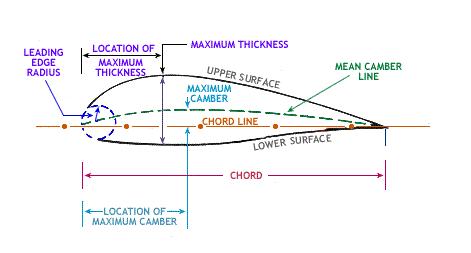
9 the wall. The velocity at the inlet was set to be 10 m/s and was kept stable for all simulations, as the results in Brandner and Walker 10 showed that the variation of Reynolds number in this case has negligible effects on the lift and drag coefficients. As the flow velocity is low enough not to cause compressibility 20, hence the flow was considered incompressible. The working fluid was defined as liquid water with a density of kg/m 3 and a viscosity of kg/ms. The SIMPLE scheme was chosen as the solution method with second-order spatial discretization. Finally, the standard initialization was used, and the solution was initialized by the values at the inlet of the control volume. The vector of the design-variables for the present study consisted of six parameters, which defined the shape of the surfboard fin; these parameters are presented in Table 2. The hydrofoil was parameterized using the NACA four-digit parametrization. NACA four-digit airfoils are defined by three parameters, namely, the maximum camber as a percentage of the chord length, the maximum camber position as tens of a percentage of the chord length and the thickness as a percentage of the chord length. The design-variables are presented in Figure 1 (a) and (b), and the computational grid created for this geometry is shown in the Figures 2, 3 and 4 along with the domain dimensions. The design space is the area bounded by the upper and lower limits of the designvariables. The upper and lower limits of the maximum camber, maximum camber position and thickness were defined according to the NACA airfoil parametrization. The upper and lower limits of the chord length, the depth and the sweep angle were defined after conducting research upon various commercial surfboard fin designs, in order to avoid any unrealistic designs.
10 2.2 Latin Hypercube Sampling The design of experiments was performed using the Latin Hypercube Sampling technique. Latin Hypercube Sampling is a statistical technique, used for obtaining a set of feasible values for the design-variables from a multidimensional distribution and is widely used in computational experiments. Further information regarding Latin Hypercube Sampling technique can be found in 21. For the construction of the Latin Hypercube Sample, the function lhsdesign provided by the statistics and machine learning toolbox of MATLAB was used. The version of the function, which was used, iteratively generates Latin Hypercube Samples to find the best one according to the maximin criterion (maximizes minimum distance between points). The resultant Latin Hypercube Sample consisted of 42 different fin designs. 2.3 Response Surface based Model (RSM) A quadratic regression polynomial was used to approximate the response of the system. Polynomial regression is a model, which can be used to approximate non-linear responses 22. The general form for polynomial regression is k y = β i x i i=0 (1) where y is the response of the system, x the design-variables vector and βi are the regression coefficients. The general form of a quadratic regression polynomial, which approximates a multivariate function, is
11 n y = β 0 + β ι x I n n 1 + β jj x j 2 + β ij x i x j n (2) i=1 j=1 i=1 j=i+1 The number of regression coefficients (N) is equal to (n + 1) (n + 2) N = 2 (3) where n is the number of the design-variables. The number of design-variables for the present case is six; hence, the regression polynomial included 28 regression coefficients. After conducting the CFD simulations, an overdetermined system was formulated with the unknown regression coefficients. This system was solved by least-squares fitting using the mldivide command of MATLAB to obtain the regression coefficients and the formula, which approximates the response of the system. The aim of the present study is to maximize the L/D ratio through the system s response of drag-per-lift values obtained through the CFD simulations. This is achieved as the optimization algorithms search for the minimum of the drag-per-lift function. The objective function of the optimisation was the resultant polynomial which represented the variation of the drag-per-lift ratio as function of the design-variables. The optimization process minimized the drag-per-lift; hence, the L/D ratio became maximum, which was the principal aim of the present study. The operating point, at which the surfboard fin was optimized, was at a velocity of 10 m/s and angle of attack 10. This angle of attack was chosen to ensure that all fin designs were evaluated before stall point, as after stall point CFD accuracy is limited due to the separation of flow and the fact that the results come from averaging. The process
12 flow chart for the Response Surface based optimization procedure is shown in the Figure Optimisation using Genetic Algorithms The resultant RSM was optimized using the genetic algorithm, provided within the MATLAB optimisation toolbox. Genetic algorithms are a subcategory of evolutionary algorithms, and the main concept, on which they are based, is to generate a set of possible solutions for a specific problem. In computer science, the procedure of searching the best solution for a given problem among multiple possible solutions is known as searching for the search space and the set of the possible solutions as the search space. Chromosome corresponds to a point in the search space. The genetic algorithm evaluate populations of chromosomes and iteratively transitions from one population to another. Another main element of a genetic algorithm is the fitness function, based on which every chromosome in a specific population is assessed and gets a corresponding score (fitness). Fitness expresses how efficiently the corresponding chromosome resolves the given problem. Further information about the genetic algorithms can be found in 23. The constructed RSM was defined as the fitness function of the optimisation problem. The constraints were defined as presented in Table 3. It must be mentioned that the last constraint is non-smooth and that is the main reason the genetic algorithm was chosen to solve the present problem, as the other optimization algorithms provided by MATLAB were not able to handle such a
13 constraint. The final optimal design resulted after improving iteratively the RSM. The basic steps of the process are summarized below: Optimal design obtained applying the optimisation algorithm to the RSM CFD analysis for the optimal design was performed and the response of the system was obtained The values of the design-variables for the optimal design were added to the set of samples of the RSM The response was added to the set of responses of the RSM The process stopped when the value obtained solving the optimisation problem differed within an acceptable tolerance in comparison with the value obtained from the numerical analysis. 3 Results and Discussion Lift and drag forces were non-dimensionalised as: L C L = 1 2 ρ υ2 Α (4) D C D = 1 2 ρ υ2 Α (5) where L is the lift force, D is the drag force, ρ is the fluid density (998.2 kg/m 2 ), υ is the fluid velocity (10 m/s) and A is the planform area of the fin ( m 2 ).
14 Three meshes were used to perform the mesh sensitivity study for the initial design namely coarse (0.6 Million elements), medium (1 Million elements) and fine (1.4 Million elements) grids. The results of the mesh sensitivity study are presented in Table 4. The results show that the medium mesh capture with sufficient accuracy the lift and drag values as the difference between the obtained values using the medium and fine meshes are negligible. The coarse mesh successfully obtained the drag value but the lift value differs substantially in comparison with the values obtained using the medium and fine meshes. Consequently, the medium mesh was used for the present study and the convergence criteria was set to of 10-6 for all cases. Pressure contours and velocity contours at the plane parallel to the bottom of the control volume and lies 0.05 m above it, are presented in the Figure 6. The pressure and velocity contours are in accordance with each other, because in areas with high velocities (upper and lower surface of the foil) low pressures are noticed, while at the leading and trailing edge, which are low-velocity areas, high pressures are observed. Moreover, the optimal fin has an efficient trailing edge of foil, as low pressures are not present at the rear part of the fin. Flow visualisations demonstrate that for the AoA = 0 the flow is uniform and stable around the fin, which is expected as the hydrofoil is symmetrical. As the AoA increases, vortices are noticed near the tip of the fin which are gradually increasing with respect to size and intensity as shown near the tip of the fin in the Figure 7. Further, the velocity contours at planes parallel to the inlet of the control volume for AoA 18 are presented in the Figure 8. Flow separation is noticed at the third and the fourth plane (right to left) near the tip of the fin; hence these
15 contours are in accordance with the aforementioned assumption, that the stall point is detected at 18. The lift and drag coefficient variations as function of angle of attack are compared with the corresponding variation obtained in Brandner and Walker 8 and the comparison is illustrated in the Figure 9. Drag coefficient variation is almost coincident for the two studies, while the curves representing the lift-coefficient variation present minor differences until an angle of attack 18. After this angle of attack, the curves follow different trends. For the present study, the stall point is detected at 18 and it is under-predicted in comparison with the study of Brandner and Walker, in which the stall point was detected at 22. The differences after the stall point could be a result of the limited accuracy of the CFD analysis at this region. Consequently, the created model is considered reliable for an angle of attack smaller than the stall point. The same meshing and CFD setup parameters (number of inflation layers, first layer thickness and size of elements) were used for simulating the fin designs of the Latin Hypercube Sample for angle of attack 10. The geometric characteristics of the optimal fin design, which resulted from the optimization process, are presented in Table 5 which is the result obtained after nine iterative improvements. Table 6 presents the results of each iterative process for all the parameters in consideration. The observed L/D ratio for the optimal design at an angle of attack 10 was 14.32, while the L/D ratio of 8.81 was observed for the initial design at the same angle of attack. This increase in the L/D ratio indicates an overall improvement of
16 approximately 62% which is a considerable improvement in the design. The difference between the drag-per-lift value obtained from the optimisation solver and the corresponding one obtained from CFD analysis indicates the error of the RSM predicting the drag-per-lift value of a fin design compared with the real value obtained from the CFD solver. The RSM error is presented as a percentage for the nine iterations in the chart of Figure 10. According to the aforementioned chart, the RSM is gradually improving until the 9 th iteration, when the RSM error was 5.28%, which was considered an acceptable tolerance for the present study. There are mainly two indicators of the efficiency of an RSM, namely the adjusted root-mean-square error and the adjusted coefficient of multiple determination. For the improved RSM, the adjusted root-mean-square error was found to be , which is relatively small compared with the drag-per-lift ratio values; hence the RSM is considered efficient based on the root-mean-square error. The adjusted coefficient of multiple determination was found to be , which is considered close enough to 1, indicating the efficiency of the RSM. Figure 11 represents the lift and drag coefficients variations for the optimal design as a function of the angle of attack. The plot demonstrates that the lift and drag variations are in accordance with the established knowledge, as drag increases along with an angle of attack, while lift increases linearly up to the stall point and then drops. The stall point was detected at angle of attack 18. A further comparison of lift per drag ratio of the two designs (initial and optimal) for more angles of attack was performed as demonstrated in the Figure 12. The comparison showed that while the initial design performs better for small angles of attack (0 and 4 ), it becomes inefficient for angles higher than 4. It can be
17 clearly seen that the L/D curve drops very quickly after 4 AoA. On the other hand, the optimal design performs much better for the angles of attack larger than 4. The aforementioned behavior is justified by the fact that the hydrofoil of the optimal design is symmetrical, while the one of the initial shape is a half section and non-symmetrical hydrofoils generate substantial lift even for small angles of attack. 4 Conclusions The result of the optimisation was a high aspect ratio, medium swept design with almost symmetrical hydrofoil. The drag-per-lift ratio values obtained from the optimisation and the CFD solver differed by 5.26%. An overall improvement of approximately 62% has been obtained for the optimal design of the surfboard fin, where the optimal design presented the maximum L/D ratio for an angle of attack of 10 among the forty-two designs of the Latin Hypercube Sample. Taking into account the lift coefficient variation of the optimal design as function of the angle of attack, the stall point was detected at 18. The comparison of the optimal design with the initial design for angles of attack from 0 to 20 showed that the initial design is more efficient for an angle of attack smaller than 4, while optimal design is more efficient beyond this angle of attack. This is attributed to the fact that the initial design is a half section hydrofoil, while the optimal design is a symmetrical hydrofoil. The visualization of the flow around the optimal fin confirmed the existence of flow separation at angle of attack 18 near the tip of the fin. The RSM based methodology (along with iterative improvements) produce satisfactory results, as the resultant fin design has similar characteristics to commercial single fins, namely big depth, high aspect ratio, symmetrical
18 hydrofoil and medium sweep angle. However, there is a lot of scope for improvements in the optimisation technique applied in the present study. Some indicative improvements could be the sensitivity study of the design-variables as well as the multimodal optimisation by replacing the non-smooth constraint and using more optimisation algorithms (e.g. multistart/singlestart SQP).
19 References: 1. Lavery, N., Foster, G., Carswell, D. and Brown, S. Optimization of Surfboard Fin Design for Minimum Drag by Computational Fluid Dynamics (Do Glass-on Fins Induce Less Drag than Boxed Fins?). 4 th International Surfing Reef Symposium, McTavish, B. A Personal History of Surfboard Design. Tracks Magazine, 3, Carroll, N. The Next Wave: A Survey of World Surfing. Queen Anne Press, London, Simpson, D., Fin Sciences, Surfboard fin lift, drag, hold and drive, [Online Resource]. Available: [Accessed: 10 th July 2015] 5. T. Hendricks, "Surfboard hydrodynamics, Part I: Drag; Part II: Pressure; Part III: Flow Separation," Surfer Magazine, Carswell, D., Lavery, N., and Brown, S., Computational Modelling of Surfboard Fins for Enhanced Performance. The Engineering of Sport 6, , 2006, Springer New York. 7. Gudimetla, P., Kelson,N., and El-Atm, B. Analysis of the hydrodynamic performance of three- and four-fin surfboards using computational fluid dynamics. Australian Journal of Mechanical Engineering, vol. 7, no. 1, pp , Carswell, D. and Lavery, N., 3D solid fin model construction from 2D shapes using non-uniform rational B-spline surfaces, Advances in Engineering Software, 37, 8, , 2006, Elsevier.
20 9. Carswell, D. Hydrodynamics of Surfboard Fins, PhD Thesis, University of Swansea, Brandner, P. and Walker, G. Hydrodynamic performance of surfboard fin. The Fifteenth Australasian Fluid Mechanics Conference, Sydney, Jeong, S., Murayama, M. and Yamamoto, K. Efficient Optimization Design Method Using Kriging Model. Journal of Aircraft, vol. 42, no. 2, pp , Painchaud-Ouellet, S. et al. Airfoil Shape Optimization Using a Nonuniform Rational B-Splines Parameterization Under Thickness Constraint. AAIA Journal, vol. 44, no. 10, pp , Chernukhin, O. and Zingg, D. Multimodality and Global Optimization in Aerodynamic Design. AAIA Journal, vol. 51, no. 6, pp , Epstein, B. et al. Comparative Study of Three-Dimensional Wing Drag Minimization by Different Optimization Techniques. Journal of Aircraft, 46-2, pp , Bray-Miners, J. et al. Biomechanics of Slalom Water Skiing. Proc IMechE Part P: J Sports Engineering and Technology, 229(1) 47 57, Luque, P. et al. Racing car chassis optimization using the finite element method, multi-body dynamic simulation and data acquisition. Proc IMechE Part P: J Sports Engineering and Technology, 227(1) 3 11, Stier, B. et al. Analysis, manufacturing, testing, and structural optimization of a novel composite kiteboard design. Proc IMechE Part P: J Sports Engineering and Technology, 229(4) , 2015.
21 18. Banks, J. et al. Kayak blade-hull interactions: A body force approach for self-propelled simulations. Proc IMechE Part P: J Sports Engineering and Technology, 228(1) 49 60, Menter, FR. Two-Equation Eddy-Viscosity Turbulence Models for Engineering Applications. AIAA Journal. 32, 8, pp , Jinping, LI et al. CFD numerical simulation of water hammer in pipeline based on the Navier-Stokes equations. ECCOMAS, Lisbon, Portugal, June Queipo, NV. et al. Surrogate-Based Analysis and Optimization. Progress in Aerospace Sciences, 41, 1, pp. 1-28, Gatignon, H. Statistical Analysis of Management Data, 2nd ed., New York: Springer Publication, Mitchell, M. An Introduction to Genetic Algorithms, The MIT Press, Cantrell, P., Airfoils, [Online Resource]. Available: [Accessed: 5 th March 2017]
22 List of Figures: Figure 1. Design-Variables, (a) Fin, (b) Hydrofoil 24. Figure 2. Computational Domain used for the Simulation along with the Dimensions. Figure 3. Grid around the surfboard fin, XY-plane. Figure 4. Grid around the surfboard fin, YZ-plane. Figure 5. Flow chart for the Response surface based optimization procedure. Figure 6. Pressure (top) and Velocity (bottom) contours for Optimal Design AOA = 0º. Figure 7. Velocity Streamlines for Optimal Design at various AoA. Figure 8. Velocity Contours Optimal Design, AoA = 18 Figure 9. Lift and Drag coefficients vs. Angle of attack, comparison with Brandner & Walker 10. Figure 10. RSM Error as function of Iterations Figure 11. Lift and Drag vs. Angle of attack (Optimal Design). Figure 12. L/D Ratio vs. Angle of Attack, Comparison of Initial and Optimal Designs.

23 (a) (b) Figure 1. Design-Variables, (a) Fin, (b) Hydrofoil 24.

24 Figure 2. Computational Domain used for the Simulation along with the Dimensions.

25 (a) (b) Figure 3. Grid around the surfboard fin, XY-plane.
26 (a) (b) Figure 4. Grid around the surfboard fin, YZ-plane.
27 Figure 5. Flow chart for the Response surface based optimization procedure.
 and Velocity (bottom)")
28 Figure 6. Pressure (top) and Velocity (bottom) contours for Optimal Design AOA = 0º.

29 Figure 7. Velocity Streamlines for Optimal Design at various AoA.

30 Figure 8. Velocity Contours Optimal Design, AoA = 18
31 C L, C D Angle of Attack ( ) cl cl_brandner and Walker cd cd_brandner and Walker Figure 9. Lift and Drag coefficients vs. Angle of attack, comparison with Brandner & Walker 10.
32 RSM Error (%) Iterations Figure 10. RSM Error as function of Iterations
33 C L, C D Angle of Attack ( ) Cl Cd Figure 11. Lift and Drag vs. Angle of attack (Optimal Design).
34 L/D Angle of Attack( ) Optimum Initial Figure 12. L/D Ratio vs. Angle of Attack, Comparison of Initial and Optimal Designs.
35 List of Tables: Table 1. Main geometry characteristics of the initial fin. Table 2. Vector of Design-variables in the Design Space. Table 3. Design constraints used for RSM. Table 4. Mesh Sensitivity Study Initial Design Table 5. Optimal Fin Geometry Characteristics. Table 6. Results of each iteration
36 Table 1. Main geometry characteristics of the initial fin. Parameter Value Chord Length (m) 0.1 Depth (m) 0.12 Sweep Angle ( ) 25 Planform Elliptical Aspect Ratio Thickness/Chord Section Half NACA 0009 Table 2. Vector of Design-variables in the Design Space. Parameter Lower Bound Upper Bound Chord Length (m) Depth (m) Sweep Angle ( ) 0 45 Max Camber (%) Max Camber Position (%) Thickness (%)
37 Table 3. Vector of Design-variables in the Design Space. Parameter Lower Bound Upper Bound Chord Length (m) Depth (m) Sweep Angle ( ) 0 45 Max Camber (%) Max Camber Position (%) Thickness (%) Drag/Lift if Max Camber=0% then Max Camber Position=0% Table 4. Mesh Sensitivity Study Initial Design Coarse Medium Fine Lift (N) Drag (N) CL CD
38 Table 5. Optimal Fin Geometry Characteristics Parameter Value Chord Length (m) Depth (m) Sweep Angle ( ) Max Camber (%) Max Camber Position (%) Thickness (%) Planform Area (m 2 ) Section Full
39 Table 6. Results of each iteration Parameters Iter. 1 Iter. 2 Iter. 3 Iter. 4 Iter. 5 Iter. 6 Iter. 7 Iter. 8 Iter. 9 Base (mm) Depth (mm) Sweep Angle ( ) Max Camber (%) Max Camber Position (%) Thickness (%) Drag-per-lift Ratio (GA) Drag-per-lift Ratio (CFD)
Investigation on 3-D Wing of commercial Aeroplane with Aerofoil NACA 2415 Using CFD Fluent
 Investigation on 3-D of commercial Aeroplane with Aerofoil NACA 2415 Using CFD Fluent Rohit Jain 1, Mr. Sandeep Jain 2, Mr. Lokesh Bajpai 3 1PG Student, 2 Associate Professor, 3 Professor & Head 1 2 3
CFD Analysis ofwind Turbine Airfoil at Various Angles of Attack
 IOSR Journal of Mechanical and Civil Engineering (IOSR-JMCE) e-issn: 2278-1684,p-ISSN: 2320-334X, Volume 13, Issue 4 Ver. II (Jul. - Aug. 2016), PP 18-24 www.iosrjournals.org CFD Analysis ofwind Turbine
AERODYNAMIC CHARACTERISTICS OF NACA 0012 AIRFOIL SECTION AT DIFFERENT ANGLES OF ATTACK
 AERODYNAMIC CHARACTERISTICS OF NACA 0012 AIRFOIL SECTION AT DIFFERENT ANGLES OF ATTACK SUPREETH NARASIMHAMURTHY GRADUATE STUDENT 1327291 Table of Contents 1) Introduction...1 2) Methodology.3 3) Results...5
COMPUTATIONAL FLUID DYNAMIC ANALYSIS OF AIRFOIL NACA0015
 International Journal of Mechanical Engineering and Technology (IJMET) Volume 8, Issue 2, February 2017, pp. 210 219 Article ID: IJMET_08_02_026 Available online at http://www.iaeme.com/ijmet/issues.asp?jtype=ijmet&vtype=8&itype=2
Aerodynamic Analysis of Blended Winglet for Low Speed Aircraft
 , July 1-3, 2015, London, U.K. Aerodynamic Analysis of Blended Winglet for Low Speed Aircraft Pooja Pragati, Sudarsan Baskar Abstract This paper provides a practical design of a new concept of massive
Design & Analysis of Natural Laminar Flow Supercritical Aerofoil for Increasing L/D Ratio Using Gurney Flap
 Design & Analysis of Natural Laminar Flow Supercritical Aerofoil for Increasing L/D Ratio Using Gurney Flap U.Praveenkumar 1, E.T.Chullai 2 M.Tech Student, School of Aeronautical Science, Hindustan University,
ANALYSIS OF AERODYNAMIC CHARACTERISTICS OF A SUPERCRITICAL AIRFOIL FOR LOW SPEED AIRCRAFT
 ANALYSIS OF AERODYNAMIC CHARACTERISTICS OF A SUPERCRITICAL AIRFOIL FOR LOW SPEED AIRCRAFT P.Sethunathan 1, M.Niventhran 2, V.Siva 2, R.Sadhan Kumar 2 1 Asst.Professor, Department of Aeronautical Engineering,
CFD ANALYSIS OF FLOW AROUND AEROFOIL FOR DIFFERENT ANGLE OF ATTACKS
 www.mechieprojects.com CFD ANALYSIS OF FLOW AROUND AEROFOIL FOR DIFFERENT ANGLE OF ATTACKS PRESENTATION OUTLINE AIM INTRODUCTION LITERATURE SURVEY CFD ANALYSIS OF AEROFOIL RESULTS CONCLUSIONS www.mechieprojects.com
Centre for Offshore Renewable Energy Engineering, School of Energy, Environment and Agrifood, Cranfield University, Cranfield, MK43 0AL, UK 2
 Fluid Structure Interaction Modelling of A Novel 10MW Vertical-Axis Wind Turbine Rotor Based on Computational Fluid Dynamics and Finite Element Analysis Lin Wang 1*, Athanasios Kolios 1, Pierre-Luc Delafin
OPTIMIZATION OF SINGLE STAGE AXIAL FLOW COMPRESSOR FOR DIFFERENT ROTATIONAL SPEED USING CFD
 http:// OPTIMIZATION OF SINGLE STAGE AXIAL FLOW COMPRESSOR FOR DIFFERENT ROTATIONAL SPEED USING CFD Anand Kumar S malipatil 1, Anantharaja M.H 2 1,2 Department of Thermal Power Engineering, VTU-RO Gulbarga,
Computational Analysis of the S Airfoil Aerodynamic Performance
 Computational Analysis of the 245-3S Airfoil Aerodynamic Performance Luis Velazquez-Araque and Jiří Nožička 2 Department of Mechanical Engineering National University of Táchira, San Cristóbal 5, Venezuela
Computational Analysis of Cavity Effect over Aircraft Wing
 World Engineering & Applied Sciences Journal 8 (): 104-110, 017 ISSN 079-04 IDOSI Publications, 017 DOI: 10.589/idosi.weasj.017.104.110 Computational Analysis of Cavity Effect over Aircraft Wing 1 P. Booma
Aerodynamics of Winglet: A Computational Fluid Dynamics Study Using Fluent
 Aerodynamics of : A Computational Fluid Dynamics Study Using Fluent Rohit Jain 1, Mr. Sandeep Jain, Mr. Lokesh Bajpai 1PG Student, Associate Professor, Professor & Head 1 Mechanical Engineering Department
AE Dept., KFUPM. Dr. Abdullah M. Al-Garni. Fuel Economy. Emissions Maximum Speed Acceleration Directional Stability Stability.
 Aerodynamics: Introduction Aerodynamics deals with the motion of objects in air. These objects can be airplanes, missiles or road vehicles. The Table below summarizes the aspects of vehicle performance
Computational Fluid Flow Analysis of Formula One Racing Car Triya Nanalal Vadgama 1 Mr. Arpit Patel 2 Dr. Dipali Thakkar 3 Mr.
 IJSRD - International Journal for Scientific Research & Development Vol. 3, Issue 02, 2015 ISSN (online): 2321-0613 Computational Fluid Flow Analysis of Formula One Racing Car Triya Nanalal Vadgama 1 Mr.
CFD Analysis of Effect of Variation in Angle of Attack over NACA 2412 Airfoil through the Shear Stress Transport Turbulence Model
 IJSRD - International Journal for Scientific Research & Development Vol. 5, Issue 02, 2017 ISSN (online): 2321-0613 CFD Analysis of Effect of Variation in Angle of Attack over NACA 2412 Airfoil through
Numerical Simulation And Aerodynamic Performance Comparison Between Seagull Aerofoil and NACA 4412 Aerofoil under Low-Reynolds 1
 Advances in Natural Science Vol. 3, No. 2, 2010, pp. 244-20 www.cscanada.net ISSN 171-7862 [PRINT] ISSN 171-7870 [ONLINE] www.cscanada.org *The 3rd International Conference of Bionic Engineering* Numerical
CFD Analysis of Giromill Type Vertical Axis Wind Turbine
 242 CFD Analysis Giromill Type Vertical Axis Wind Turbine K. Sainath 1, T. Ravi 2, Suresh Akella 3, P. Madhu Sudhan 4 1 Associate Pressor, Department Mechanical Engineering, Sreyas Inst. Engg. & Tech.,
Improved Aerodynamic Characteristics of Aerofoil Shaped Fuselage than that of the Conventional Cylindrical Shaped Fuselage
 International Journal of Scientific & Engineering Research Volume 4, Issue 1, January-213 1 Improved Aerodynamic Characteristics of Aerofoil Shaped Fuselage than that of the Conventional Cylindrical Shaped
CFD AND EXPERIMENTAL STUDY OF AERODYNAMIC DEGRADATION OF ICED AIRFOILS
 Colloquium FLUID DYNAMICS 2008 Institute of Thermomechanics AS CR, v.v.i., Prague, October 22-24, 2008 p.1 CFD AND EXPERIMENTAL STUDY OF AERODYNAMIC DEGRADATION OF ICED AIRFOILS Vladimír Horák 1, Dalibor
5th Symposium on Integrating CFD and Experiments in Aerodynamics (Integration 2012) th Symposium on Integrating CFD and Experiments in Aerodynam
 th Symposium on Integrating CFD and Experiments in Aerodynam") 5th Symposium on Integrating CFD and Experiments in Aerodynamics (Integration 202) 36 Multi-objective Optimization of Airfoil of Mars Exploration Aircraft using Evolutionary Algorithm Gaku Sasaki Tomoaki
5th Symposium on Integrating CFD and Experiments in Aerodynamics (Integration 202) 36 Multi-objective Optimization of Airfoil of Mars Exploration Aircraft using Evolutionary Algorithm Gaku Sasaki Tomoaki
CFD ANALYSIS AND COMPARISON USING ANSYS AND STAR-CCM+ OF MODEL AEROFOIL SELIG 1223
 International Journal of Mechanical Engineering and Technology (IJMET) Volume 8, Issue 11, November 2017, pp. 312 318, Article ID: IJMET_08_11_034 Available online at http://www.iaeme.com/ijmet/issues.asp?jtype=ijmet&vtype=8&itype=11
A COMPUTATIONAL STUDY ON THE DESIGN OF AIRFOILS FOR A FIXED WING MAV AND THE AERODYNAMIC CHARACTERISTIC OF THE VEHICLE
 28 TH INTERNATIONAL CONGRESS OF THE AERONAUTICAL SCIENCES A COMPUTATIONAL STUDY ON THE DESIGN OF AIRFOILS FOR A FIXED WING MAV AND THE AERODYNAMIC CHARACTERISTIC OF THE VEHICLE Jung-Hyun Kim*, Kyu-Hong
Aerodynamic Analysis of a Symmetric Aerofoil
 214 IJEDR Volume 2, Issue 4 ISSN: 2321-9939 Aerodynamic Analysis of a Symmetric Aerofoil Narayan U Rathod Department of Mechanical Engineering, BMS college of Engineering, Bangalore, India Abstract - The
Effect of Co-Flow Jet over an Airfoil: Numerical Approach
 Contemporary Engineering Sciences, Vol. 7, 2014, no. 17, 845-851 HIKARI Ltd, www.m-hikari.com http://dx.doi.org/10.12988/ces.2014.4655 Effect of Co-Flow Jet over an Airfoil: Numerical Approach Md. Riajun
Numerical and Experimental Investigation of the Possibility of Forming the Wake Flow of Large Ships by Using the Vortex Generators
 Second International Symposium on Marine Propulsors smp 11, Hamburg, Germany, June 2011 Numerical and Experimental Investigation of the Possibility of Forming the Wake Flow of Large Ships by Using the
Effect of Diameter on the Aerodynamics of Sepaktakraw Balls, A Computational Study
 ISSN 1750-9823 (print) International Journal of Sports Science and Engineering Vol. 03 (2009) No. 01, pp. 017-021 Effect of Diameter on the Aerodynamics of Sepaktakraw Balls, A Computational Study Zahari
Anna University Regional office Tirunelveli
 Effect of Tubercle Leading Edge Control Surface on the Performance of the Double Delta Wing Fighter Aircraft P Sharmila 1, S Rajakumar 2 1 P.G. Scholar, 2 Assistant Professor, Mechanical Department Anna
A COMPARATIVE STUDY OF MIX FLOW PUMP IMPELLER CFD ANALYSIS AND EXPERIMENTAL DATA OF SUBMERSIBLE PUMP
 IMPACT: International Journal of Research in Engineering & Technology (IMPACT: IJRET) ISSN 2321-8843 Vol. 1, Issue 3, Aug 2013, 57-64 Impact Journals A COMPARATIVE STUDY OF MIX FLOW PUMP IMPELLER CFD ANALYSIS
J. Szantyr Lecture No. 21 Aerodynamics of the lifting foils Lifting foils are important parts of many products of contemporary technology.
 J. Szantyr Lecture No. 21 Aerodynamics of the lifting foils Lifting foils are important parts of many products of contemporary technology. < Helicopters Aircraft Gliders Sails > < Keels and rudders Hydrofoils
Volume 2, Issue 5, May- 2015, Impact Factor: Structural Analysis of Formula One Racing Car
 Structural Analysis of Formula One Racing Car Triya Nanalal Vadgama 1, Mr. Arpit Patel 2, Dr. Dipali Thakkar 3, Mr. Jignesh Vala 4 Department of Aeronautical Engineering, Sardar Vallabhbhai Patel Institute
INVESTIGATION OF PRESSURE CONTOURS AND VELOCITY VECTORS OF NACA 0015IN COMPARISON WITH OPTIMIZED NACA 0015 USING GURNEY FLAP
 INVESTIGATION OF PRESSURE CONTOURS AND VELOCITY VECTORS OF NACA 0015IN COMPARISON WITH OPTIMIZED NACA 0015 USING GURNEY FLAP 1 ANANTH S SHARMA, 2 SUDHAKAR S, 3 SWATHIJAYAKUMAR, 4 B S ANIL KUMAR 1,2,3,4
External Tank- Drag Reduction Methods and Flow Analysis
 External Tank- Drag Reduction Methods and Flow Analysis Shaik Mohammed Anis M.Tech Student, MLR Institute of Technology, Hyderabad, India. G. Parthasarathy Associate Professor, MLR Institute of Technology,
The effect of back spin on a table tennis ball moving in a viscous fluid.
 How can planes fly? The phenomenon of lift can be produced in an ideal (non-viscous) fluid by the addition of a free vortex (circulation) around a cylinder in a rectilinear flow stream. This is known as
CFD ANALYSIS OF EFFECT OF FLOW OVER NACA 2412 AIRFOIL THROUGH THE SHEAR STRESS TRANSPORT TURBULENCE MODEL
 CFD ANALYSIS OF EFFECT OF FLOW OVER NACA 2412 AIRFOIL THROUGH THE SHEAR STRESS TRANSPORT TURBULENCE MODEL 1 SHIVANANDA SARKAR, 2SHAHEEN BEG MUGHAL 1,2 Department of Mechanical Engineering, ITM University,
ROAD MAP... D-1: Aerodynamics of 3-D Wings D-2: Boundary Layer and Viscous Effects D-3: XFLR (Aerodynamics Analysis Tool)
") Unit D-1: Aerodynamics of 3-D Wings Page 1 of 5 AE301 Aerodynamics I UNIT D: Applied Aerodynamics ROAD MAP... D-1: Aerodynamics of 3-D Wings D-: Boundary Layer and Viscous Effects D-3: XFLR (Aerodynamics
Unit D-1: Aerodynamics of 3-D Wings Page 1 of 5 AE301 Aerodynamics I UNIT D: Applied Aerodynamics ROAD MAP... D-1: Aerodynamics of 3-D Wings D-: Boundary Layer and Viscous Effects D-3: XFLR (Aerodynamics
Effect of High-Lift Devices on Aircraft Wing
 IOSR Journal of Engineering (IOSRJEN) ISSN (e): 2250-3021, ISSN (p): 2278-8719 PP 01-05 www.iosrjen.org Effect of High-Lift Devices on Aircraft Wing Gaurav B. Mungekar 1, Swapnil N. More 1, Samadhan V.
STUDY OF VARIOUS NACA SERIES AEROFOIL SECTIONS AND WING CONTOUR GENERATION USING CATIA V5
 STUDY OF VARIOUS NACA SERIES AEROFOIL SECTIONS AND WING CONTOUR GENERATION USING CATIA V5 Pawan Kumar Department of Aeronautical Engineering, Desh Bhagat University, Punjab, India ABSTRACT Aerofoil is
CFD Study of Solid Wind Tunnel Wall Effects on Wing Characteristics
 Indian Journal of Science and Technology, Vol 9(45), DOI :10.17485/ijst/2016/v9i45/104585, December 2016 ISSN (Print) : 0974-6846 ISSN (Online) : 0974-5645 CFD Study of Solid Wind Tunnel Wall Effects on
Experimental and Theoretical Investigation for the Improvement of the Aerodynamic Characteristic of NACA 0012 airfoil
 International Journal of Mining, Metallurgy & Mechanical Engineering (IJMMME) Volume 2, Issue 1 (214) ISSN 232 46 (Online) Experimental and Theoretical Investigation for the Improvement of the Aerodynamic
CFD ANALYSIS OF AIRFOIL SECTIONS
 CFD ANALYSIS OF AIRFOIL SECTIONS Vinayak Chumbre 1, T. Rushikesh 2, Sagar Umatar 3, Shirish M. Kerur 4 1,2,3 Student, Jain College of Engineering, Belagavi, Karnataka, INDIA 4Professor, Dept. of Mechanical
Senior mechanical energy conversion trends
 Senior mechanical energy conversion trends Introduction and Analysis to fan blade profile and CFD Simulation Of An Appropriate Blade Profile for improving energy efficiency HAMED ROSTAMALIZADEH 95742906
An Impeller Blade Analysis of Centrifugal Gas Compressor Using CFD
 An Impeller Blade Analysis of Centrifugal Gas Compressor Using CFD Vivek V. Kulkarni Department of Mechanical Engineering KLS Gogte Institute of Technology, Belagavi, Karnataka Dr. Anil T.R. Department
Know the ropes. Assystem Investigates the America s Cup Wing Sails
 24 Know the ropes Marine Know the ropes Assystem Investigates the America s Cup Wing Sails Alessandro Fiumara - Assystem France and ISAE-Supaéro Julien Senter - Assystem France Nicolas Gourdain and Vincent
Reduction of Skin Friction Drag in Wings by Employing Riblets
 Reduction of Skin Friction Drag in Wings by Employing Riblets Kousik Kumaar. R 1 Assistant Professor Department of Aeronautical Engineering Nehru Institute of Engineering and Technology Coimbatore, India
High Swept-back Delta Wing Flow
 Advanced Materials Research Submitted: 2014-06-25 ISSN: 1662-8985, Vol. 1016, pp 377-382 Accepted: 2014-06-25 doi:10.4028/www.scientific.net/amr.1016.377 Online: 2014-08-28 2014 Trans Tech Publications,
Optimized Natural-Laminar-Flow Airfoils
 Optimized Natural-Laminar-Flow Airfoils J. Driver and D. W. Zingg University of Toronto Institute for Aerospace Studies 4925 Dufferin Street, Toronto, Ontario Canada, M3H 5T6 A two-dimensional Newton-Krylov
The Effect of Icing on the Performance of NACA Wind Turbine Blade
 International Journal of Current Engineering and Technology E-ISSN 2277, P-ISSN 237 5 27 INPRESSCO, All Rights Reserved Available at http://inpressco.com/category/ijcet Research Article The Effect of Icing
CFD DESIGN STUDY OF A CIRCULATION CONTROL INLET GUIDE VANE OF AN AEROFOIL
 Int. J. Mech. Eng. & Rob. Res. 2012 Manjunath Ichchangi and Manjunath H, 2012 Research Paper ISSN 2278 0149 www.ijmerr.com Vol. 1, No. 3, October 2012 2012 IJMERR. All Rights Reserved CFD DESIGN STUDY
The Usage of Propeller Tunnels For Higher Efficiency and Lower Vibration. M. Burak Şamşul
 The Usage of Propeller Tunnels For Higher Efficiency and Lower Vibration M. Burak Şamşul ITU AYOC 2014 - Milper Pervane Teknolojileri Company Profile MILPER is established in 2011 as a Research and Development
CFD SIMULATION STUDY OF AIR FLOW AROUND THE AIRFOIL USING THE MAGNUS EFFECT
 Magnus effect, simulation, air flow Patryk SOKOŁOWSKI *, Jacek CZARNIGOWSKI **, Paweł MAGRYTA *** CFD SIMULATION STUDY OF AIR FLOW AROUND THE AIRFOIL USING THE MAGNUS EFFECT Abstract The article presents
Computational fluid dynamics analysis of a mixed flow pump impeller
 MultiCraft International Journal of Engineering, Science and Technology Vol. 2, No. 6, 2010, pp. 200-206 INTERNATIONAL JOURNAL OF ENGINEERING, SCIENCE AND TECHNOLOGY www.ijest-ng.com 2010 MultiCraft Limited.
Low Speed Wind Tunnel Wing Performance
 Low Speed Wind Tunnel Wing Performance ARO 101L Introduction to Aeronautics Section 01 Group 13 20 November 2015 Aerospace Engineering Department California Polytechnic University, Pomona Team Leader:
ScienceDirect. Investigation of the aerodynamic characteristics of an aerofoil shaped fuselage UAV model
 Available online at www.sciencedirect.com ScienceDirect Procedia Engineering 90 (2014 ) 225 231 10th International Conference on Mechanical Engineering, ICME 2013 Investigation of the aerodynamic characteristics
COMPUTATIONAL FLOW MODEL OF WESTFALL'S LEADING TAB FLOW CONDITIONER AGM-09-R-08 Rev. B. By Kimbal A. Hall, PE
 COMPUTATIONAL FLOW MODEL OF WESTFALL'S LEADING TAB FLOW CONDITIONER AGM-09-R-08 Rev. B By Kimbal A. Hall, PE Submitted to: WESTFALL MANUFACTURING COMPANY September 2009 ALDEN RESEARCH LABORATORY, INC.
NUMERICAL INVESTIGATION FOR THE ENHANCEMENT OF THE AERODYNAMIC CHARACTERISTICS OF AN AEROFOIL BY USING A GURNEY FLAP
 Geotec., Const. Mat. & Env., ISSN:2186-2990, Japan, DOI: http://dx.doi.org/10.21660/2017.34.2650 NUMERICAL INVESTIGATION FOR THE ENHANCEMENT OF THE AERODYNAMIC CHARACTERISTICS OF AN AEROFOIL BY USING A
Numerical Investigation of Multi Airfoil Effect on Performance Increase of Wind Turbine
 International Journal of Engineering & Applied Sciences (IJEAS) International Journal of Engineering Applied Sciences (IJEAS) Vol.9, Issue 3 (2017) 75-86 Vol.x, Issue x(201x)x-xx http://dx.doi.org/10.24107/ijeas.332075
CFD Analysis of Effects of Surface Fouling on Wind Turbine Airfoil Profiles
 International Journal of Energy and Power Engineering 215; 4(5-1): 1-11 Published online August 31, 215 (http://www.sciencepublishinggroup.com/j/ijepe) doi: 1.11648/j.ijepe.s.215451.11 ISSN: 2326-957X
SEMI-SPAN TESTING IN WIND TUNNELS
 25 TH INTERNATIONAL CONGRESS OF THE AERONAUTICAL SCIENCES SEMI-SPAN TESTING IN WIND TUNNELS S. Eder, K. Hufnagel, C. Tropea Chair of Fluid Mechanics and Aerodynamics, Darmstadt University of Technology
Numerical Analysis of Wings for UAV based on High-Lift Airfoils
 Numerical Analysis of Wings for UAV based on High-Lift Airfoils Sachin Srivastava Department of Aeronautical Engineering Malla Reddy College of Engineering & Technology, Hyderabad, Telangana, India Swetha
Design and Development of Micro Aerial Vehicle
 Advances in Aerospace Science and Applications. ISSN 2277-3223 Volume 4, Number 1 (2014), pp. 91-98 Research India Publications http://www.ripublication.com/aasa.htm Design and Development of Micro Aerial
INTERFERENCE EFFECT AND FLOW PATTERN OF FOUR BIPLANE CONFIGURATIONS USING NACA 0024 PROFILE
 Proceedings of the International Conference on Mechanical Engineering 211 (ICME211) 18-2 December 211, Dhaka, Bangladesh ICME11-FL-1 INTERFERENCE EFFECT AND FLOW PATTERN OF FOUR BIPLANE CONFIGURATIONS
Incompressible Potential Flow. Panel Methods (3)
") Incompressible Potential Flow Panel Methods (3) Outline Some Potential Theory Derivation of the Integral Equation for the Potential Classic Panel Method Program PANEL Subsonic Airfoil Aerodynamics Issues
Incompressible Potential Flow Panel Methods (3) Outline Some Potential Theory Derivation of the Integral Equation for the Potential Classic Panel Method Program PANEL Subsonic Airfoil Aerodynamics Issues
AERODYNAMICS I LECTURE 7 SELECTED TOPICS IN THE LOW-SPEED AERODYNAMICS
 LECTURE 7 SELECTED TOPICS IN THE LOW-SPEED AERODYNAMICS The sources of a graphical material used in this lecture are: [UA] D. McLean, Understanding Aerodynamics. Arguing from the Real Physics. Wiley, 2013.
NUMERICAL INVESTIGATION OF AERODYNAMIC CHARACTERISTICS OF NACA AIRFOIL WITH A GURNEY FLAP
 Int. J. Mech. Eng. & Rob. Res. 2012 MasoudJahanmorad Nouri et al., 2012 Research Paper ISSN 2278 0149 www.ijmerr.com Vol. 1, No. 3, October 2012 2012 IJMERR. All Rights Reserved NUMERICAL INVESTIGATION
Fin hydrodynamics of a windsurfer L. Sutherland & RA. Wilson Department of Ship Science, University of Southampton, Highfield, Southampton,
 Fin hydrodynamics of a windsurfer L. Sutherland & RA. Wilson Department of Ship Science, University of Southampton, Highfield, Southampton, 1 Introduction Windsurfing is a relatively new technical sport
Optimization of a Wing-Sail shape for a small boat
 STAR Global Conference 2014 Vienna, March 17-19 Optimization of a Wing-Sail shape for a small boat G. Lombardi, F. Cartoni, M. Maganzi Dept. of Civil and Industrial Engineering of Pisa Aeronautical Section
Aerodynamic Analyses of Horizontal Axis Wind Turbine By Different Blade Airfoil Using Computer Program
 ISSN : 2250-3021 Aerodynamic Analyses of Horizontal Axis Wind Turbine By Different Blade Airfoil Using Computer Program ARVIND SINGH RATHORE 1, SIRAJ AHMED 2 1 (Department of Mechanical Engineering Maulana
Influence of wing span on the aerodynamics of wings in ground effect
 Influence of wing span on the aerodynamics of wings in ground effect Sammy Diasinos 1, Tracie J Barber 2 and Graham Doig 2 Abstract A computational fluid dynamics study of the influence of wing span has
EXPERIMENTAL ANALYSIS OF THE CONFLUENT BOUNDARY LAYER BETWEEN A FLAP AND A MAIN ELEMENT WITH SAW-TOOTHED TRAILING EDGE
 24 TH INTERNATIONAL CONGRESS OF THE AERONAUTICAL SCIENCES EXPERIMENTAL ANALYSIS OF THE CONFLUENT BOUNDARY LAYER BETWEEN A FLAP AND A MAIN ELEMENT WITH SAW-TOOTHED TRAILING EDGE Lemes, Rodrigo Cristian,
Computational Analysis of Blunt Trailing Edge NACA 0012 Airfoil
 Computational Analysis of Blunt Trailing Edge NACA 2 Airfoil Anusha K Department of Aerospace Engineering Madras Institute of Technology, India anusugan7@gmail.com Abstract Blunt trailing edge airfoil
OPTIMIZING THE LENGTH OF AIR SUPPLY DUCT IN CROSS CONNECTIONS OF GOTTHARD BASE TUNNEL. Rehan Yousaf 1, Oliver Scherer 1
 OPTIMIZING THE LENGTH OF AIR SUPPLY DUCT IN CROSS CONNECTIONS OF GOTTHARD BASE TUNNEL Rehan Yousaf 1, Oliver Scherer 1 1 Pöyry Infra Ltd, Zürich, Switzerland ABSTRACT Gotthard Base Tunnel with its 57 km
Unsteady Aerodynamics of Tandem Airfoils Pitching in Phase
 Unsteady Aerodynamics of Tandem Airfoils Pitching in Phase Ravindra A Shirsath and Rinku Mukherjee Abstract This paper presents the results of a numerical simulation of unsteady, incompressible and viscous
A Numerical Simulation Comparing the Efficiencies of Tubercle Versus Straight Leading Edge Airfoils for a Darrieus Vertical Axis Wind Turbine
 A Numerical Simulation Comparing the Efficiencies of Tubercle Versus Straight Leading Edge Airfoils for a Darrieus Vertical Axis Wind Turbine By: Ross Neal Abstract: The efficiencies of sinusoidal and
International Journal of Innovative Research in Science, Engineering and Technology Vol. 2, Issue 5, May 2013
 PERFORMANCE PREDICTION OF HORIZONTAL AXIS WIND TURBINE BLADE HardikPatel 1, SanatDamania 2 Master of Engineering Student, Department of Mechanical Engineering, Government Engineering College, Valsad, Gujarat,
MODELING AND SIMULATION OF VALVE COEFFICIENTS AND CAVITATION CHARACTERISTICS IN A BALL VALVE
 Proceedings of the 37 th International & 4 th National Conference on Fluid Mechanics and Fluid Power FMFP2010 December 16-18, 2010, IIT Madras, Chennai, India FMFP2010 341 MODELING AND SIMULATION OF VALVE
2-D Computational Analysis of a Vertical Axis Wind Turbine Airfoil
 2-D Computational Analysis of a Vertical Axis Wind Turbine Airfoil Akshay Basavaraj1 Student, Department of Aerospace Engineering, Amrita School of Engineering, Coimbatore 641 112, India1 Abstract: This
Numerical simulation of aerodynamic performance for two dimensional wind turbine airfoils
 Available online at www.sciencedirect.com Procedia Engineering 31 (2012) 80 86 International Conference on Advances in Computational Modeling and Simulation Numerical simulation of aerodynamic performance
ANALYSIS OF TRANSONIC FLOW OVER SUPERCRITICAL AIRFOIL USING CFD FOR GAS TURBINE BLADES
 ANALYSIS OF TRANSONIC FLOW OVER SUPERCRITICAL AIRFOIL USING CFD FOR GAS TURBINE BLADES Kushal Gandecha 1 and Kalpit P. Kaurase 2 Abstract 1 Department of Mechanical Engineering, School of Engineering and
Determination of the wind pressure distribution on the facade of the triangularly shaped high-rise building structure
 Determination of the wind pressure distribution on the facade of the triangularly shaped high-rise building structure Norbert Jendzelovsky 1,*, Roland Antal 1 and Lenka Konecna 1 1 STU in Bratislava, Faculty
Jet Propulsion. Lecture-17. Ujjwal K Saha, Ph. D. Department of Mechanical Engineering Indian Institute of Technology Guwahati
 Lecture-17 Prepared under QIP-CD Cell Project Jet Propulsion Ujjwal K Saha, Ph. D. Department of Mechanical Engineering Indian Institute of Technology Guwahati 1 Lift: is used to support the weight of
Air Craft Winglet Design and Performance: Cant Angle Effect
 Journal of Robotics and Mechanical Engineering Research Air Craft Winglet Design and Performance: Cant Angle Effect Eslam Said Abdelghany 1, Essam E Khalil 2*, Osama E Abdellatif 3 and Gamal elhariry 4
Journal of Engineering Science and Technology Review 9 (5) (2016) Research Article. CFD Simulations of Flow Around Octagonal Shaped Structures
 (2016) Research Article. CFD Simulations of Flow Around Octagonal Shaped Structures") Jestr Journal of Engineering Science and Technology Review 9 (5) (2016) 72-76 Research Article JOURNAL OF Engineering Science and Technology Review www.jestr.org CFD Simulations of Flow Around Octagonal
Jestr Journal of Engineering Science and Technology Review 9 (5) (2016) 72-76 Research Article JOURNAL OF Engineering Science and Technology Review www.jestr.org CFD Simulations of Flow Around Octagonal
STUDY OF THE INFLUENCE OF A GAP BETWEEN THE WING AND SLOTTED FLAP ON THE AERODYNAMIC CHARACTERISTICS OF ULTRA-LIGHT AIRCRAFT WING AIRFOIL
 Review of the Air Force Academy No 3 (30) 2015 STUDY OF THE INFLUENCE OF A GAP BETWEEN THE WING AND SLOTTED FLAP ON THE AERODYNAMIC CHARACTERISTICS OF ULTRA-LIGHT AIRCRAFT WING AIRFOIL 1. INTRODUCTION
Two-way Fluid Structure Interaction (FSI) Analysis on the Suction Valve Dynamics of a Hermetic Reciprocating Compressor
 Analysis on the Suction Valve Dynamics of a Hermetic Reciprocating Compressor") Volume 118 No. 18 2018, 4241-4252 ISSN: 1311-8080 (printed version); ISSN: 1314-3395 (on-line version) url: http://www.ijpam.eu ijpam.eu Two-way Fluid Structure Interaction (FSI) Analysis on the Suction
Volume 118 No. 18 2018, 4241-4252 ISSN: 1311-8080 (printed version); ISSN: 1314-3395 (on-line version) url: http://www.ijpam.eu ijpam.eu Two-way Fluid Structure Interaction (FSI) Analysis on the Suction
Static Extended Trailing Edge for Lift Enhancement: Experimental and Computational Studies
 Static Extended Trailing Edge for Lift Enhancement: Experimental and Computational Studies T. Liu, J. Montefort, W. Liou Western Michigan University Kalamazoo, MI 49008 and Q. Shams NASA Langley Research
Numerical and Experimental Investigations of Lift and Drag Performances of NACA 0015 Wind Turbine Airfoil
 International Journal of Materials, Mechanics and Manufacturing, Vol. 3, No., February 2 Numerical and Experimental Investigations of Lift and Drag Performances of NACA Wind Turbine Airfoil İzzet Şahin
A Research on the Airflow Efficiency Analysis according to the Variation of the Geometry Tolerance of the Sirocco Fan Cut-off for Air Purifier
 A Research on the Airflow Efficiency Analysis according to the Variation of the Geometry Tolerance of the Sirocco Fan Cut-off for Air Purifier Jeon-gi Lee*, Choul-jun Choi*, Nam-su Kwak*, Su-sang Park*
C-1: Aerodynamics of Airfoils 1 C-2: Aerodynamics of Airfoils 2 C-3: Panel Methods C-4: Thin Airfoil Theory
 ROAD MAP... AE301 Aerodynamics I UNIT C: 2-D Airfoils C-1: Aerodynamics of Airfoils 1 C-2: Aerodynamics of Airfoils 2 C-3: Panel Methods C-4: Thin Airfoil Theory AE301 Aerodynamics I : List of Subjects
INVESTIGATION OF HYDRODYNAMIC PERFORMANCE OF HIGH-SPEED CRAFT RUDDERS VIA TURBULENT FLOW COMPUTATIONS, PART I: NON-CAVITATING CHARACTERISTICS
 Journal of Marine Science and Technology, Vol. 13, No. 1, pp. 61-72 (2005) 61 Short Paper INVESTIGATION OF HYDRODYNAMIC PERFORMANCE OF HIGH-SPEED CRAFT RUDDERS VIA TURBULENT FLOW COMPUTATIONS, PART I:
Performance of GOE-387 Airfoil Using CFD
 International Journal of Aerospace Sciences 2017, 5(1): 1-7 DOI: 10.5923/j.aerospace.20170501.01 Performance of GOE-387 Airfoil Using CFD Mohamed A. Fouad Kandil *, Abdelrady Okasha Elnady Mechatronics
CIRCULATION CONTROLLED AIRFOIL ANALYSIS THROUGH 360 DEGREES ANGLE OF ATTACK
 Proceedings of the ASME 2009 3rd International Conference of Proceedings Energy Sustainability of ES2009 Energy Sustainability ES2009 July July 19-23, 2009, 2009, San San Francisco, California, USA ES2009-90341
Numerical study of aeroelasticity of sails
 Numerical study of aeroelasticity of sails Alessandro Leone, Luciano Teresi* SMFM@DiS, Università Roma Tre, Roma, Italy * Corresponding author: Dip. of Studies on Structures, via Corrado Segre 6, 00146
EXPERIMENTAL ANALYSIS OF FLOW OVER SYMMETRICAL AEROFOIL Mayank Pawar 1, Zankhan Sonara 2 1,2
 EXPERIMENTAL ANALYSIS OF FLOW OVER SYMMETRICAL AEROFOIL Mayank Pawar 1, Zankhan Sonara 2 1,2 Assistant Professor,Chandubhai S. Patel Institute of Technology, CHARUSAT, Changa, Gujarat, India Abstract The
AIRFOIL PROFILE OPTIMIZATION OF AN AIR SUCTION EQUIPMENT WITH AN AIR DUCT
 THERMAL SCIENCE, Year 2015, Vol. 19, No. 4, pp. 1217-1222 1217 AIRFOIL PROFILE OPTIMIZATION OF AN AIR SUCTION EQUIPMENT WITH AN AIR DUCT by Li QIU a,b, Rui WANG a,*, Xiao-Dong CHEN b, and De-Peng WANG
WESEP 594 Research Seminar
 WESEP 594 Research Seminar Aaron J Rosenberg Department of Aerospace Engineering Iowa State University Major: WESEP Co-major: Aerospace Engineering Motivation Increase Wind Energy Capture Betz limit: 59.3%
Study on the Shock Formation over Transonic Aerofoil
 Advances in Aerospace Science and Applications. ISSN 2277-3223 Volume 3, Number 2 (2013), pp. 113-118 Research India Publications http://www.ripublication.com/aasa.htm Study on the Shock Formation over
An Analysis of Lift and Drag Forces of NACA Airfoils Using Python
 An Analysis of Lift and Drag Forces of NACA Airfoils Using Python 1. Tarun B Patel, Sandip T Patel 2, Divyesh T Patel 3, Maulik Bhensdadiya 4 1 M E scholar Government Engineering College, Valsad, Gujarat,
Aerodynamic study of a cyclist s moving legs using an innovative approach
 Aerodynamic study of a cyclist s moving legs using an innovative approach Francesco Pozzetti 30 September 2017 Abstract During a period of four weeks in September, I completed a research project in fluid
STUDY OF MODEL DEFORMATION AND STING INTERFERENCE TO THE AERODYNAMIC ESTIMATIONS OF THE CAE-AVM MODEL
 STUDY OF MODEL DEFORMATION AND STING INTERFERENCE TO THE AERODYNAMIC Min ZHONG, Ganglin WANG, Jun HUA Chinese Aeronautical Establishment #2 Anwai Beiyuan, 100012, Beijing, China Keywords: Aerodynamic design,