Dynamic Omnidirectional Kicks on Humanoid Robots
|
|
|
- Edwina Dickerson
- 5 years ago
- Views:
Transcription

1 THE UNIVERSITY OF NEW SOUTH WALES THE SCHOOL OF COMPUTER SCIENCE AND ENGINEERING Dynamic Omnidirectional Kicks on Humanoid Robots By: Belinda Teh A Thesis submitted for the degree of COMPUTER SCIENCE August 24, 2012 Supervisors: Bernhard Hengst and Maurice Pagnucco Assessor: Claude Sammut
2 Abstract One of the challenges of humanoid robot soccer is being able to kick balls and score goals as quickly and accurately as possible. As such, the purpose of this thesis was to create a more efficient kick and apply it in a robot behaviour. The following report thus documents the improvements made to runswift s entry in the Robocup Standard Platform League of First, the developments in kinematics to achieve a greater sense of balance and accuracy within the body model are presented, which proved useful to many other runswift modules such as vision and localisation. Next, a dynamic omnidirectional kick was created within the kick engine with the attributes of power, accuracy, and reliability to combat slow line up and reaction times. This was supplemented by the speedy and manoeuvrable dribble kicks integrated into the walk engine, which proved useful for retaining ball possession even with other competing robots nearby. Methods of arm swings in the front getup routines are also discussed to combat the large number of falls that can occur as a result of multiple robots competing for the ball. Finally, these efforts were combined into a striker behaviour based on state machines and decision trees, which showed significant speed increases over strikers from previous years. The team performed well at the Robocup competition with the striker scoring the most goals out of all the teams, and runswift achieving third place overall.
3 Acknowledgements Firstly, to my fellow team members - Peter, Ritwik, Roger, Sean, Youssef, Sam, Carl, Richard - thank you for all your help and contributions over the past few months. And to Bernhard, for always being ready to give up time to support and encourage us, offer insight and ideas, and keep us on track. I really enjoyed working with you guys, so thanks for making the lab and runswift a fun place to be. Thank you to Brad for always taking care of us, and to Morri and Claude for their advice along the way. Thank you to the others on level 3 for patiently sharing the lab and your ideas with us, as well as the School of CSE for the continued support. Thank you to Em for looking out for me, and to past runswift members, Brock, Oleg, for all your help. And finally, thank you to all my friends and family for having to put up with my lengthy absences over the past few months. i
4 Contents 1 Introduction Motivation Balance Accuracy Speed Reliability Striker Aims Outline Background Locomotion and Balancing Centre of Mass Kicking runswift Overview of runswift Motion Architecture Kinematics Centre of Mass Body Lean Results Balancing with Centre of Mass ii
5 3.3.2 Body Lean in Pose Evaluation Kick Engine Background Kick Parameters Kick Phases Angle Kick Turn Kick Taking a Turn Step Kick Adjustments Dynamic Adjustments Results Omniside Reach Omnidirectional Accuracy Kick Power Simple Striker Test Evaluation Dribble Kick Engine Background Dribble Parameters Dribble Phases Forward Dribble Kicks Kick Adjustments Dynamic Adjustments Walk and Dribble Integration - the Forward Shuffle Results Evaluation iii
6 6 Pos Actions Front Getup Routine Arm Swing Results Evaluation Striker Behaviour Low Level State Machine - Shoot Penalty Shoot-out States High Level Decision Tree - Striker Kick Off Strategy Robot Avoidance Close Range Goals Illegal Defender Penalty Results Striker Test Robocup Competition Evaluation Future Work Kinematics Walking and Kicking Getup Routines Striker Behaviour Conclusion 65 Bibliography 66 iv
7 Chapter 1 Introduction 1.1 Motivation In order to win a soccer match, one must first be able to keep the ball away from opponents and then be able to score. As such, being able to dribble and kick a ball into the goals is critical to the success of any team. More importantly, the faster and more versatile the kick, the higher the chances of scoring before the other team. These issues of speed, accuracy and reliability are becoming an increasing focus in the Robocup Standard Platform League [1], especially with the advancements in the Aldebaran Naos [2] and increased game pace. Robocup 1 is an international robotics competition aimed at promoting research of artificial intelligence through soccer matches. Ultimately, the goal is to create a team of autonomous humanoid soccer players that can compete against the human champions of the World Cup. While the competition has since expanded to many other leagues, the application of this thesis is in the Standard Platform League (SPL). The main focus of this league is on the software behind autonomous soccer playing robots as opposed to the hardware, as all teams use the Aldebaran Nao as the common robot platform. A common approach to scoring in current Robocup SPL matches is to position the striker robot facing forward on the straight line formed by the ball and the goal before kicking the ball with the front of the foot. Unfortunately, this method is limited by its inflexibility and slow speed as the ideal position might not always be available or difficult to achieve. Humans on the other hand, are able to control the ball accurately, quickly and reliably in multiple directions on the fly. If we could emulate this behaviour in the Aldebaran Naos, the chances of scoring fast goals and dominating the competition would be greatly improved

8 Figure 1.1 Schematic of the Aldebaran Nao Balance An important underlying aspect to kicking is first achieving a greater understanding of the body model to remain balanced. With 21 degrees of freedom, coordinating the Nao s movement for locomotive tasks can become complicated. Studying the mechanics linking all 21 joints and modelling this kinematics chain with all its constraints is thus particularly important. Without an accurate kinematics model and centre of mass, making adjustments while standing on a single support foot can be quite a challenge. Unless the appropriate counter balances can be determined, lifting a foot to kick would not even be possible Accuracy There needs to be a certain degree of control and accuracy to a kick, especially since missing the goal and causing the ball to go out would consequently hand the advantage over to the other team. Currently, the robot s pose is determined by the kinematic links from the cameras in the robot s head to the point touching the ground on the robot s foot. The calculation of its stance can then be used to compute ground distances and orientations of objects seen in camera frames. Thus by improving the accuracy of kinematics and the body model, the robot s sense of the world around it will be improved, resulting in more accurate localisation. This added benefit means that the ball can also be pinpointed more precisely, allowing for more accurate foot contact when kicking. 2
9 1.1.3 Speed No matter how intricate or accurate the kick might be, it would be of no use if an opponent robot managed to clear the ball first. As such, speed is integral to the creation of an omnidirectional kick. This calls for improvements not only in preparation times for kicks and actual kick durations, but also in the integration between walking and kicking Reliability Due to the unexpected and external influences that can happen during games, it is crucial that a certain level of flexibility and reliability be obtained. The kick needs to be able to adapt to events such as the ball being knocked around slightly or getting pushed by another robot in the middle of a kick, which can happen a lot in tussles for the ball. With a dynamic kick that can clear a ball even in critical situations, the striker robot would be better equipped to score goals despite tough competition Striker Incorporating these advances into striker behaviour was a huge motivation for runswift 2012 as it addressed one of the big issues in previous competitions. Even though the team s robots often managed to walk to the ball first, a lot of time would then be wasted in lining up and performing the actual kick. This pause would typically allow enough time for an opponent robot to dribble the ball away, or at least get into a position to block the goal. Hence with the addition of a dynamic omnidirectional kick, the team would gain a significant advantage in soccer matches. Apart from walking and kicking, static movements, which are simply defined using a sequence of joint values, are also required during competition. A particular example is the getup routine, which the striker is often subject to as falling robots tend to occur as a result of robots clashing to get to the ball. As such, important considerations must also be made for balance, speed and reliability in these routines. Balancing is required to enable the robot to stand back up on its feet, while speed is important for getting the robot back into the game as quickly as possible, and finally reliability is needed to ensure its ability to get up in all sorts of situations. 3
10 1.2 Aims The aims of this thesis can be summarised into the following three areas: Incorporate mass and lean into kinematics chain calculations to improve balancing and recovery as well as the accuracy of vision and localisation estimations. Develop a dynamic and omnidirectional kick that is both fast and powerful while remaining balanced. Implement a striker behaviour for Robocup Standard Platform League matches with improved line up and kick times. 1.3 Outline Chapter 2: describes related work in the balancing of humanoid robots and dynamic kicking as well as the background of runswift s previous strategies. Chapter 3: encompasses the mass and lean related additions in the kinematics system and evaluates their effectiveness. Chapter 4: explains the methods behind developing an omnidirectional kick, as well as the improvements in the kick engine, and presents the resulting findings. Chapter 5: discusses the approach behind developing increasingly integrated dribbles within the walk and dribble kick engines. Chapter 6: analyses the methods used when programming set actions, in particular the front getup routines, and discusses how effective they are. Chapter 7: describes the mechanics of runswift 2012 s striker behaviour including the underlying state machine and decision tree, and discusses its performance. Chapter 8: offers suggestions for future development in the areas related to kinematics, motion and behaviour. Chapter 9: concludes and summarises the findings of this report. 4
11 Chapter 2 Background 2.1 Locomotion and Balancing Centre of Mass Balancing has long been a challenge in humanoid locomotion, with active stabilisation in particular becoming a growing concern. Popular methods have involved the learning of joint movements to control the robot s centre of mass and zero moment point (ZMP) as shown in Figure 2.1, as well as the application of human-like fall avoidance strategies [3 5]. Figure 2.1 Relationship between the centre of mass and the zero moment point [6] 5
12 The ZMP is defined as the point on the ground where all acting forces equate to zero, in other words, no more movement would be produced. The centre of mass is defined as the average location of within a group of solids as weighted by each of their respective masses. It is calculated as follows, where x i and m i refer to the location and mass of each individual solid and M is the total mass. CoM = 1 mi x i M However, due to the cost and manufacturing limits in hardware on commercially available humanoid robots, not all balancing options are always feasible. Notable recent approaches include the development of a full body push recovery controller on the DARwin-OP [7]. Inspired by the human reflex of using our ankles, hips, and stepping to regain balance, the three biomechanically motivated push recovery strategies were written. By applying controlled pushes upon the robot through the use of a motorised moving platform, hierarchical controller parameters to integrate both the walk and the recovery strategies were reinforcement learnt [8] on the robot itself. Their experiments proved successful, demonstrating that despite the lack of specialised hardware, recovery from external influences, even while moving in different directions, was possible. Figure 2.2 Inverted pendulum model and its potential energy, with the body s centre of mass as the swinging point mass of the pendulum In terms of the Standard Platform League, teams such as B-Human from the University of Bremen have done some similar work on balancing the Aldebaran Naos [9]. An inverted pendulum as shown in Figure 2.2 was used to model the Nao, and the motion of the centre of mass was tracked according to its position and velocity relative to the origin of the pendulum [10]. With dynamic adjustment of the walk s support phases (see Figure 2.3), the pendulum aimed to keep its origin in the optimal position beneath the centre of the feet and the centre of mass at an ideal movement for the next leg swing. To compensate for hardware 6
13 inaccuracies and external forces, sensory feedback was also integrated. By observing the differences between the desired centre of mass and the recorded centre mass, appropriate adjustments could be made to reduce the error. Finally, iterative inverse kinematics was used to calculate the relevant joint angles for achieving the required centre of mass position [11]. Further improvements were made in 2011, in particular to the dynamic handling of external influences. Rather than simply performing one counter action to return the centre of mass to its ideal position once a disturbance had occurred, the whole trajectory was modified to continue along with the disturbance and would be continually adjusted for stability [12]. With these features, B-Human managed to create a speedy yet robust walk which was a contributing factor to their first place championship. Figure 2.3 Support phases during a bipedal walk cycle [6] Kicking Besides its application in walks, the centre of mass has many uses in motion engines in general, in particular for kicking. The common and underlying methods to all these different movements, whether it be walking or kicking, is to keep the ZMP and centre of mass within the support polygon of the foot and at a stable velocity in order to remain upright. A kick is conventionally carried out as a defined set of motion sequences by interpolating between key points, and the majority of SPL teams have adopted this type of approach [13 16]. However without dynamic reactive strategies, these hardcoded movements would be unable to handle any external disturbances. For example, updates in the ball position, nudges from another robot or existing sways while transitioning from walking could cause such a kick to fail. B-Human 2011 have instead moved to a dynamic approach which defines the kick motion as a set of Bezier curves that can be adjusted online [17]. The control points of each curve 7
14 are dynamic and decided at the start of each kick phase, allowing the foot to adjust to the current ball position. The final control points can be further transformed to rotate according to direction parameters from behaviour, permitting switches between forward and side kicks. In terms of balancing, the centre of mass is projected to the ground and its desired position is calculated by computing the harmonic mean of future positions of the support foot, allowing it to adapt in preparation. Differences between the projected and measured centre of mass are used as input into a PID controller for the robot s tilt angle. The resulting values are then transformed into rotation angles using the estimation of the height of the centre of mass with Pythagoras Theorem. However, B-Human discovered that balancing using the centre of mass alone was not sufficient, so an additional controller was added to further compensate for unexpected disturbances. Angular velocity as measured from the gyroscopes is distinguished from velocity introduced by disturbance compensation as opposed to actual desired velocity. The error between the two is then fed into a PID controller, which provides offset angles for balancing via the hip pitch and hip roll joints. To test the effectiveness of the balancing controllers, a 500g weighted pendulum was swung into the back of a robot at a height of 35cm while it was standing on one leg [17]. Ten trials without the controllers in action resulted in the robot falling down every time. In comparison, the balancing robot was able to recover in around 2.5 seconds for all ten trials. With this kick, the deviation in angular accuracy was 3.32 on average, with the ball typically reaching a distance of 5 to 6 metres. Once again, B-Human were clearly successful, obtaining first place during Robocup 2011 with one of the most powerful and accurate kicks in the competition. Although the direction was limited to forward or side kicks, their line up placement and walk integration was sufficient enough that additional directions were not particularly necessary. Humboldt is another SPL team that left the key frame technique behind in favour of using adaptive motion control to create a dynamic kick [18]. Their kick was split into four phases: preparation to shift the robot s weight, retraction to pull the foot back, execution to perform the kick and wrap-up to return the foot to the ground. If any external influences occurred that meant carrying out the kick was no longer possible, the robot would be able to jump straight to the wrap-up phase. Dynamic adaptation was introduced in the retraction phase, which made use of visual input to adjust the foot position before executing the kick. The Nao s foot was assumed to be round like a ball in order to simplify the modelling of the collision between the two. Given a kick direction, the ideal point of collision could then be calculated. Their next step was to generate the reachable space of the kicking foot based on physical experiments on the robot, and together with the collision point, plan the motion trajectory of the kick. The retraction point should be as far as possible from the collision point for maximal impact, however angle and distance to the ball requirements must also 8
15 be met. Instead of using the fastest reachable path to the point, the shortest one was used to prevent unwanted collisions, for example with the ground, with adjustments according to the reachability grid. A prediction of the resultant kick movement was then compared to the requested direction, and the precision of the match was used to decide whether the kick should be executed or not. All these kicking phases were also subject to the balancing strategy of keeping the centre of mass in the centre of the support polygon as shown in Figure 2.4. Sensor data was used to calculate the centre of mass and the support polygon, then a P controller was used to adjust the inclination of the robot s body such that the difference between the two was minimised. Since the leg pose and hip position were already set by the reachable trajectory, only the body inclination, or lean, was dynamically adjusted. Figure 2.4 Centre of mass movement relative to the support polygon as a Nao transfers its weight to a single foot without stabilisation (left) as opposed to with stabilisation (right) [18] The experiments to test these were broken down into two areas - adaptivity of direction and adaptivity of ball position [18]. First, the kick was set to a direction of 0 and incremented at an angle of 10 up until 90. They found that there was a negative offset in all the trials with the largest errors at 20, which could be explained by inaccuracies in their assumptions such as the foot being round like a circle. In general though, the error in the resultant direction remained less than 10 for kick directions less than 20 with a maximal distance of around 3 metres, and between for the rest, reaching distances up to 1 metre. The second experiment involved kicking straight while changing the position of the ball randomly within a 25x20cm rectangle. Most of the 100 kicks reached distances between 1 and 2.8 metres, though kick positions past 10cm in either direction tended to lose their accuracy. Finally, it should be noted that the robot was able to balance on one foot and adjust dynamically to the different ball positions and directions during the experiments. 1 While Humboldt s 1 See video example of experiments at dynamic_kick.mp4 9
16 dynamic balancing and omnidirectional ability were impressive, the lack of power and speed in their kicks brought down their competitive potential. There is also the question of what is the best and most efficient way to perform a kick. In 2010, Hausknecht and Stone decided to apply machine learning, which had typically already been used for walking and in simulation, to the task of kicking on a real robot - a Sony Aibo [19]. Parameters for the kick were simply raw joint angles, with the learning space reduced by taking advantage of the Aibo s symmetry. These were then learnt using Hill Climbing and Policy Gradient algorithms over 860 kicks up an inclined ramp. The ramp s height, and hence slope, was adjusted such that the robot would be unable to kick the ball off the end. Some human input was required to feed the result back to the robot, namely the distance of the kicked ball and the time it took for the ball to be kicked then return to the robot, and to reposition the robot for the next kick. On average, the learned kick managed to move a ball cm, about 50cm more than one of Robocup s top kicks with about 30cm less in standard deviation and a maximal distance of 628cm. However, this was at a sideways loss of accuracy of about 4cm per metre, which was not too significant, but was likely due to power and distance being emphasised during the learning process instead. Since passing was key amongst the Aibo League, it was also important that the kick be controllable and predictable. By varying the amount of time spent in the kicking phase, they managed to gather data of the ball distance according to kick frames, which could then be modelled using a quadratic function. It was found that within a range of cm, the learned kick was accurate to within 45.5cm on average. Considering this distance is within 1-2 Aibo lengths, using this method to create a variable distance kick was useful, though perhaps learning for this specific task could further improve accuracy. Apart from being successful at producing a more powerful kick than Robocup s top teams through machine learning, their methods had also saved developers the painstaking time taken to manually tune such parameters. However, this was only applied to the Sony Aibo which has a much simpler joint configuration than the Aldebaran Nao, though many of the concepts in learning could still be ported over. Now that the robots in use in the soccer leagues are beginning to resemble humans more and more, the notion of biomechanics is becoming increasingly valuable when programming humanoid robots. By modelling the human body with 34 degrees of freedom in a motion capture and analysis tool, a team from Japan experimented with the manipulability and joint-torque properties of a human as they performed a kick [20]. The key results they found were that both the lower and upper torsos were equally important in kicking, as the rotational energy transmitted between the two is crucial in the kicking motion. Combined with the manipulability of the kicking leg and shorter periods, the eventual velocity on impact with 10
17 the ball could be maximised. As mentioned earlier, biomechanics has already begun to be applied in walking. While the Naos are still far off from having the same manoeuvrability as humans, there are still some concepts worth noting for kicking, such as rotation in the upper torso, that show future promise runswift Originally, in the transition from 4-legged Sony Aibos to the Naos, runswift 2008 calculated the centre of mass and integrated it into their walk balancing [21]. However since Aldebaran did not provide the precise centre of mass for each link in the robot, several assumptions had to be made, causing a loss of accuracy in the calculated centre of mass. Kicks were created by specifying set parameters such as time period and joint angles across different kick phases. The centre of mass was also applied in kicks for additional stability, but unfortunately, the Power Kick developed never managed to be utilised in an actual game due to behavioural issues. In addition to the Power Kick from 2008, a new kick, known as the Bunt Kick, was created in 2009 [22]. Joint poses were captured and played back using an action creation system until a satisfactory sequence was found. While the ball would not be kicked quite as far, the total execution time taken was 4s as opposed to 9s for the Power Kick. Unfortunately due to behavioural decisions, it too was not used in actual games that year. It was at this point that Tay discovered that the asymmetry present in the Naos, which meant that simply mirroring the joint poses for left and right kicks was unsuccessful, and tweaks had to be made to properly balance both sides while walking. During 2010, existing systems were overhauled and a brand new runswift architecture was implemented [16]. One of the new developments involved using the foot sensors and accelerometers to determine the centre of pressure. This was used in the creation of a walk (named FastWalk) to apply feedback control and retain balance. While the centre of mass was not included, FastWalk was useful for its purposes - to walk fast in a relatively straight line, and became one of the signatures of the runswift team. However, it was too unstable on single support phase, so an alternative had to be used when transitioning into kicks. A second walk was also in development (named SlowWalk), which was used as the intermediary. The SlowWalk motion was used to rock the robot back and forth between a single support foot, while the swing foot executed the kick by following a series of sinusoidal joint trajectories. Forward, side and back kicks were created to expand the reach of the robot s kicks, though only the first two were used in competition. Considering runswift 2010 placed second in the world, the new ground set by the team had proved worthwhile. 11
18 An attempt was made at an omnidirectional kick in a separate Kick Generator, as opposed to the Action or Walk Generators like the previous work [16]. A state-based model was used with 6 states as follows: 1. Lean: The robot shifts its weight on to the support foot. 2. Lift: The free leg is lifted into the air. 3. Line-up: The leg is dynamically lined up to the position of the ball along the robot s coronal axis. If kicking at an angle, the leg also rotates using the robot s pelvis joint, known as the HipYawPitch joint. 4. Kick: The swing of the kick is dynamically executed to connect the tip of the foot to the ball at the appropriate position and direction. 5. Un-line-up: The robot returns the leg to a neutral position, still off the ground. 6. Un-lean: The robot shifts its weight back to both feet and lowers its kicking foot. This omnidirectional kick was able to extend its reach by 5cm in front of the foot and 12cm to the side of the centre of the robot, which would be approximately 7.5cm from the side of the centre of the foot. However it seemed that it was unable to correctly calculate the offset in its foot position relative to the ball, as 45 kicks were typically offset by 3cm. This could have been due to a number of reasons, such as inaccuracies in the ball filter or discrepancies in the kinematics used to calculate the position. Unfortunately due to it s incomplete omnidirectionality, slow execution time, and weaker power even in its forward kicks with a maximal distance of 4 metres, it was eventually scrapped. By 2011, the walk had been restructured, though the notion of having a slow conservative walk and a fast aggressive walk still remained. The main balancing issue remaining was the walk s slow ramp up period, as finding an appropriate hip rock to create a smooth walking motion was unsuccessful. Further developments had been made in balancing though, notably White s Open Challenge in step and ankle placement using reinforcement learning [23]. The robot was modelled using an inverted pendulum with the help of kinematic information, the on-board IMU (Inertial Measurement Unit) and a simple Kalman Filter to track its states. Ankle balancing control was applied by using the ZMP to determine the location of pressure on the foot and applying the appropriate rotations if necessary. Step control simply involved altering the walk cycle to place the foot directly at the position requested by the Reinforcement Learning Planner. Though these methods enabled a robot to reliably handle obstacles twice as high as compared to a robot without them, and the demonstration placed 3rd in Robocup 2011 s Open Challenge, it was not made ready for competition. 12
19 In terms of kicks, one of the significant improvements was the incorporation of the kick engine into the walk engine for smoother and faster transitions [23]. Standard kicks were similar to previous years, with both forward and side kicks being defined by a sequence of interpolated sinusoidal trajectories. Including a weight transfer time of 4.5s, at maximum power their execution times were 6.7s and 7.8s respectively. On the left and right foot, the side kick managed a range of m and m respectively, while the forward kick managed a range of m and m respectively. The significant deficiency in the right forward kick despite the mirrored kick motions can be attributed to the motors in the right leg not being able to keep up to the speed of a full swing, reflecting the asymmetry of the Naos. Dribble kicks were also developed to quickly move the ball short distances which could be executed within a walk cycle with a period of 1.4s. On the left and right foot, the side dribble managed a range of m and m respectively, while the forward dribble managed a range of m and m respectively. Once again, large differences in the side dribbles reflect the differences in strength of the left and right hip joints in the Naos. While a third kind of kick, known as the shuffle kick, was also attempted in order to dribble and move with the ball, it was too unstable to be used. As such, dribble kicks were used rather effectively in tussle situations against enemy robots while mainly left forward kicks were used for big goal shots, which were some of the most powerful in the competition as even the goalie could potentially score goals from the far end of the field. With the advent of the Nao v4s in 2012, many improvements were made possible. In terms of locomotion, the advances in the IMU and gyroscopes meant that the body lean could be estimated more accurately. While Liu had begun to apply these additions to the walk [24], there were also applications for body lean in kicks. Not only could it be used for dynamic balancing during kicks, but for improving the robot s estimate of its kinematics, indirectly increasing the accuracy of localisation and foot positioning for kicks. The desire to create a new walk for 2012 with less stress on the motors and improved smoothness led to a greater need of the proper calculation of the centre of mass. By tracking its position and velocity, it could be used to help control walk cycles and improve balancing in general. This was also now possible due to updates in Aldebaran documentation specifying the exact dimensions and locations of each link and their respective centre of masses. Improvements in motors also meant that the robots should be capable of moving their joints faster, more accurately and with more power. One of the major issues in 2011 was the speed of the striker s line up and kick, which could be addressed by making the whole process faster and more versatile. Hence, this project was begun to address the need to improve issues in balancing, create an omnidirectional kick and ultimately develop a new striker that would be able to score goals quickly and efficiently. 13
20 2.2 Overview of runswift Motion Architecture Current motion architecture is based on the original rewrite of runswift 2010 [16] and built upon by White in 2011 [23]. The motion module is run in its own thread with the highest priority on the robot, as joint angles need to be calculated at 100 frames per second to maintain stability. The MotionAdapter class controls this thread and is the first entry point for receiving robot data, such as an ActionCommand from a behaviour request. This data would have originated from the Blackboard, a common data structure that all runswift modules use to share information. Figure 2.5 Overview of basis of motion architecture It then calls upon its three children objects in turn: Touch - receives and filters input from the Nao s sensors. Generator - processes the behaviour request and sensor input to generate appropriate joint values and subsequent odometry. Effector - uses generated joint values to output robot action. Once the cycle is complete, data such as odometry, sensor values and current action are passed back to the Blackboard for use in other modules. There is one main generator class, the DistributedGenerator, that calls upon subsequent generators depending on the requested action. Focus will be mostly applied to the development within the PlannedWalkGenerator and its related objects as it is the handler for all walk, kick and dribble actions. 14
21 Figure 2.6 Walk, kick and dribble generator architecture ActionCommand: contains a collection of data types (Body, Head and LEDs) to communicate parameters set by the Behaviour module. BodyModel: contains the inverted pendulum model and relevant kinematics data, such as the ZMP. JointValues: contains a value for each of the robot s joints which will be passed to an Effector object. PlannedWalkGenerator: plans out high level steps for the walk depending on the requested ActionCommand while ensuring that it remains synchronised with the current state of the body model and sensor values. SensorValues: received from a Touch object with current values from each of the robot s sensors and joints. WalkEngineRequest: data structure constructed by PlannedWalkGenerator for storing information based on the behaviour request. WalkEngine: uses body model, sensor data and the WalkEngineRequest passed in to handle lower level details of the walk and generate walk cycles. It also transitions in and out of the integrated kick engine to execute kicks and dribbles depending on the WalkEngineRequest s parameters. It is this class that actually constructs the data for setting the JointValues. 15
22 Chapter 3 Kinematics One of the first steps towards enhancing the motion module was to improve the body model and kinematics of the robot. A more accurate kinematics model would allow for quick responses to any disturbances and finer control over the robot s movement, producing more effective walking and kicking techniques. Another particular application of kinematics is the calculation of the chain between the camera in the head and the foot on the ground in order to create the Pose and keep track of the robot s current stance. The Pose object is instrumental in the runswift pipeline as it is used to construct the horizon, which is defined as the line parallel to the y-axis of the robot and at an infinite distance away. It is particularly useful for vision algorithms as it can help place constraints on the position of certain objects, for example, it should not be possible for a ball or any part of the field to appear above the horizon. Pose is also responsible for converting camera coordinates of objects seen in vision into field coordinates that are relevant to localisation and behaviour. For example, depending on the location of projected field points, they could be classified into groups to form key features such as corners or the centre circle [25]. Due to its links to the Pose and the related vision and localisation modules, the kinematics calculations were originally carried out as part of the Perception thread [16]. However, to keep up to date with its use in the Motion thread, which was run 100 times a second as opposed to 30, it was accordingly shifted over. A slight lag was introduced to compensate for the difference in cycles between the two threads. Along with newly available information on the Nao v4s, such as the improved IMU and hardware documentation from Aldebaran, many areas could benefit from these updates. 16

23 3.1 Centre of Mass A robot s centre of mass can provide a lot of information about its current state of balance, and has proven useful in many dynamic balancing, walking and kicking techniques as discussed in Chapter 2. Aldebaran documentation [26] provided the mass and centre of mass of each of the solids that compose the Nao relative to the zero posture (see Figure 3.1), and from these it was possible to derive the robot s centre of mass at each cycle. The Denavit-Hartenburg (DH) convention [27] was applied to determine the positions and masses of each of the solids relative to the torso s frame of reference. Tables describe the DH parameters used for the right side of the body, with the left being symmetrical. Note that some lines could be further condensed if only relative positioning was required, but are left in such a form so that the mass can be determined in each joint s frame of reference before continuing the transforms down the chain. For more practical uses of the centre of mass, it would be converted into the foot s or the ground s frame of reference for walking and balancing, with body lean taken into account. Figure 3.1 The Nao s Zero Posture and frame of reference 17
24 Joint Frame a α d θ Head Yaw 0 0 neckoffsetz Cy Head Pitch 0 π/2 0 Cp Torso 0 π/2 0 0 Table 3.1: DH Parameters used between head and torso Joint Frame a α d θ 0 0 shoulderoffsetz 0 0 π/2 shoulderoffsety 0 R Shoulder Pitch 0 π 0 Sp 0 π/2 0 0 R Shoulder Roll Sr upperarmlength π/2 -elbowoffsety 0 0 π/2 0 π/2 R Elbow Yaw 0 π/2 0 Ey 0 π/2 0 π/2 R Elbow Roll 0 π/2 0 Er Torso 0 π/ Body Lean Table 3.2: DH Parameters used between right arm and torso With Liu s work [24] on the new accelerometers and gyroscopes in the IMU within the Nao v4, a better estimate of the body lean became available in the robot model. Calculations so far had all assumed that the Nao s foot would be flat on the ground, however this was often not the case. Despite aiming to always keep the foot parallel to the ground, external disturbances such as bounces in the ground or pushing from other robots would disrupt kinematics. This would have particularly detrimental effects on vision and the Pose, which is used to determine the horizon and object locations on the field depending on their camera coordinates. Continuing along the chain of modules, problems in vision and the detection of key field features would affect localisation and the filtered ball location and velocity. In turn, this would ruin the precision of line ups and kicks. As such, the previous method of using purely forward kinematics to calculate the chain from the foot to the camera [28] was rewritten. Instead, the chain was separated into two sections. First, forward kinematics was used to estimate the height and location of the hip. This point would then be rotated by the forward and sideways body lean. Finally, the rest of the chain from the body to the camera was evaluated using forward kinematics once again. 18
25 3.3 Results Joint Frame a α d θ 0 0 -hipoffsetz 0 0 π/2 hipoffsety 0 Hip Yaw Pitch 0 3π/4 0 Hyp 0 π/ π/2 0 π/2 R Hip Roll 0 π/2 0 Hr 0 π/2 0 π/2 0 π/2 0 0 R Hip Pitch 0 π/2 0 Hp 0 π/ thighlength 0 R Knee Pitch 0 π/2 0 Kp 0 π/ tibialength 0 R Ankle Pitch 0 π/2 0 Ap 0 π/ π/2 R Ankle Roll 0 π/2 0 Ar Torso 0 π/2 0 π/2 Table 3.3: DH Parameters used between right leg and torso Balancing with Centre of Mass To test its effectiveness in dynamic balancing, a simple behaviour was written to respond to any offsets in the calculated centre of mass. The motor for the Nao s left shoulder roll was made limp so that the arm could be freely moved up and down at varying angles. The change in centre of mass on the y axis would then be iteratively added to, or subtracted from, the joint value for the right shoulder roll until the centre of mass restabilised within a threshold close to 0. The left shoulder was moved at 20 intervals with the first and last being limited to the minimum value of approximately 1.7 and maximum value of approximately 75. While compensating for the imbalance in the centre of mass, with examples as shown in Figure 3.2, the joint value for both shoulder rolls was recorded at each tick. Figure 3.3 displays a comparison of the right shoulder roll joint value at each left shoulder roll joint value over time while Figure 3.4 displays the same experiment but with opposite arms. There is a noticeable bias towards the left arm, which is discussed later in Section

 as")


26 Figure 3.2 Right shoulder adjusting as left shoulder is set to 20, 40, 60 and 75 Figure 3.3 Joint values ( ) as right shoulder roll adjusts to changes in left shoulder roll Figure 3.4 Joint values ( ) as left shoulder roll adjusts to changes in right shoulder roll 20
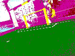
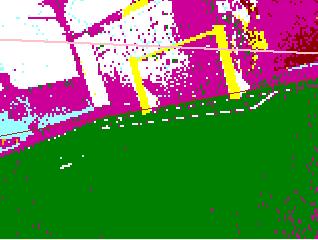
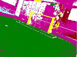
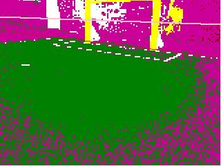
27 3.3.2 Body Lean in Pose The methods behind the Pose object involved the use of the Nao s kinematics chain to transform between the location of objects relative to the camera and objects relative to the ground. As such, the differences in Pose s accuracy were used as a measure of the improvements caused by the addition of the body lean in kinematics. To test its effectiveness, a Nao was placed on the field and made to look at several key features both with and without the incorporation of body lean in its calculations. Screenshots were taken with the robot in its default stand stance and when it was tilted in both the x and y directions. For consistency, the robot was propped up by placing the same 5cm high roll of field tape beneath its foot to achieve a sideways tilt across both experiments. Similarly, a 2.5cm high roll of masking tape was used to prop the robot s feet up and achieve a forwards and backwards tilt across both experiments. Figure 3.5 shows the robot s view of the horizon when using the original method of calculating the Pose on the right, while the left displays a comparison of the same view, but with body lean incorporated. Figure 3.6 demonstrates the same concept but with projected field points and the centre circle. 3.4 Evaluation Asymmetry in the Naos, as Tay had first suspected in 2009 [22], is confirmed once again with the results from the centre of mass. Understandably, the graphs demonstrate some lag in the adjusting shoulder as the robot received, processed and then reacted to the sensor data. This is particularly apparent in the spikes towards the start of the graphs when the arms first start to move. However, they both show a significant weighting towards the left arm being lifted higher than the right arm. The only exception to this is in the plateau at the end of the second graph, though this was due to the left shoulder roll reaching its maximum joint value. Differences in maximal joint values only serve to further the notion of the left and right joints being asymmetric, though some of the variation could be explained by the difference in stiffness and power of the motors. Aldebaran documentation does state that the right shoulder is heavier than the left by 0.17g, with the whole right side of the body weighing 1.69g more than the left. Though this would cause a slight bias, it seems doubtful that it should cause such large gaps, which are as much as 18 at its maximum angle. Other explanations could include inaccuracies in sensor readings or even perhaps that the placement of parts within the Nao s body are biased towards the right. Calculating the body lean from sensor data has proven to make a significant difference, with the Nao being able to correctly detect the horizon and centre circle no matter its orientation. 21
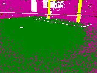
28 Comparatively, when the Nao was tilted without incorporating the estimation of its body lean, it typically detected the horizon at incorrect angles and the centre circle at incorrect locations. In extreme cases, such as in Figure 3.6 e), the points failed to resemble a circle at all. Since the Nao was not localised, the detected circle in these images did not coincide with the white field circle, but appeared simply in the robot s relative frame of reference. It is interesting to note that without the body lean from sensor data, the horizon and centre circle were still incorrect even without a tilt in the robot s stance. This was caused by the lack of full stiffness in the motors and the default stand stance having a slight bias towards leaning forward. The Pose is still occasionally subject to inaccuracies, though this is most likely due to noise in sensor data, as well as the lack of a z-axis gyroscope in the IMU affecting the estimation of the body lean. Overall the improvements in kinematics have furthered our understanding of the Nao s body model and increased its usefulness in other modules. 22

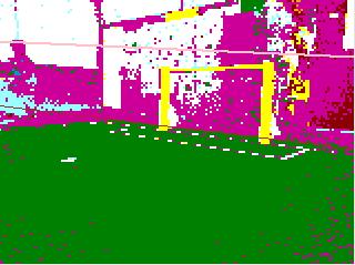
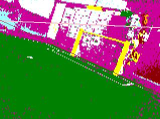
29 Figure 3.5 Comparison of horizons calculated with lean (left) versus without lean (right) (a) No tilt (b) Tilted left (c) Tilted right (d) Tilted back (e) Tilted forward 23


 Tilted")
30 Figure 3.6 Comparison of field points (blue) and detected centre circle (red) with lean (left) versus without lean (right), with the Nao s camera view in the middle (a) No tilt (b) Tilted left (c) Tilted right (d) Tilted back (e) Tilted forward 24
31 Chapter 4 Kick Engine A kick is an action performed by moving a robot s joints in predefined manner as instructed by a state machine of timed phases (see Section 4.1.2). Since kicks are the main driving force behind moving the ball around the field and ultimately scoring goals, it is important for robots to be able to consistently kick balls with power, speed and accuracy. To achieve such movement while standing on a single foot, elements from kinematics must be used to remain balanced. Fine tuned control over the robot s body is also needed to ensure the kicking foot is in line to contact the ball with maximal power and at the appropriate angle. For the speed and flexibility of being able to kick a ball at any angle with minimal line up time, the development of an omnidirectional kick was pursued. 4.1 Background While both forward and side kicks were available last year, these sections will mainly focus on forward kicks since the side kicks were decommissioned this year in favour of an omnidirectional kick Kick Parameters As it was in 2011 [23], many variables were used to manage the state of the kicks within the integrated kick and walk engine: currentactiontype: used within the walk engine to determine if it is currently kicking, walking, or dribbling 25
32 walkenginerequest: stores the incoming request from the walk planner at the start of the kick as the new current kick information iskicking: if the Nao is in the process of kicking haskicked: set to true after finishing a kick T : period of a walk or step cycle t: current position within that cycle footoffset: the phase offset depending on the foot, typically either 0 or T/2 coronalamplitude: amplitude of the Nao s coronal rock kickt : total period of all the kick phases kickt: current position within the kick phases lastkicktime: set upon finishing a kick forward/footpos: forward position of the foot during a kick left/footside: side position of the foot during a kick (only used in side kicks) kneepitch: how much the kicking leg is swung back and forth stepheight: how high the foot is lifted during a kick Kick Phases As it was in 2011 [23], the phases of the forward kick were as follows: Preparation As soon as a kick request is received, it is saved into the walkenginerequest and the preparation begins. The currentactiontype is set to KICK, however the walk is allowed to continue until the correct support foot is on the ground. Namely, when t = footoffset, where footoffset = 0 would be the start of a left step cycle for kicking with the left foot, or footoffset = T/2 for the right foot. Once the timing conditions have been met, iskicking is set to true, T is set to a new slower period of 4.5 seconds, haskicked is set to false and coronalamplitude is set to
33 Weight Transfer (Start) Using the recently set parameters from the preparation phase, weight transfer to the support foot is executed through a slow walk cycle. Note that this is caused by the combination of lengthening the period (T ) and the increase in coronal rock (coronalamplitude) which compensates for the slower movement. Halfway through the step, the walk cycle is paused such that the Nao is balanced on its support foot with its kicking foot lifted at stepheight in the air. Back Phase At the start of any kick, it is assumed that the foot s position and knee pitch are at 0. The actual kick sequence then begins here, with the foot s forward position being interpolated to -70mm and the knee pitch swinging back to 20 over a period of 0.4 seconds. Kick Swing Phase This is the core phase of the kick, where the foot actually makes contact with the ball. The foot s forward position is interpolated to +70mm and the knee pitch is swung forward to -20. Depending on the requested kick power, the period can vary from 0.2 seconds (maximum power) to 0.5 seconds (minimum power). Follow Through Phase To ensure kick phase completion and stabilisation, this phase waits at the final kick position for 1 second. End Phase The foot is returned to its original state by interpolating the forward position and knee pitch back to 0 over 0.6 seconds. At this point the kicking foot is lifted halfway through a walk cycle with its mass balanced over its support foot. Weight Transfer (End) Once the End Phase has completed as checked by kickt > kickt, kickt and lastkicktime are set back to 0 and iskicking is set to false. T is still at the slow period of 4.5s, and t is 27
34 updated to footoffset +T/4 to reflect the point in the walk cycle where the foot is returned to the ground and weight is shifted back into double support phase. The movement of the legs through these phases are summarised in Figure 4.1. In total, it typically takes 4.45 seconds to execute a forward kick. Figure 4.1 Leg movement through the main forward kick phases: preparation, start weight transfer, back phase, swing phase, end phase, end weight transfer 4.2 Angle Kick Initial attempts to create an omnidirectional kick involved the investigation of previous years work, namely the use of the hip yaw pitch joint to achieve an angular kick. Instead of creating a separate omnidirectional kick, the change in the hip yaw pitch joint was incorporated into the existing forward kick. However due to its exclusion from the foot position s kinematics, setting the forward and left/footside parameters at the same time did not actually give correct results, with the ankle often tilting away from the ground. Combined with the lack of precision required in the line ups, the kick tended to be rather inaccurate. Other issues included the fact that it could only kick balls at very slight angles, otherwise the kicking leg would knock into the support leg while swinging. 4.3 Turn Kick Previous approaches of turning the hip yaw pitch joint to achieve an angle kick were subject to inaccuracies, low power, complicated kinematics, and tricky line ups. Thus it was decided that it would be more ideal to reuse proven existing infrastructure, namely, the inverse kinematics used to turn whilst keeping the feet parallel to the ground when walking. Using this within the kick engine would allow enough control to turn the robot at an angle specified by behaviour, after which a normal forward kick could be carried out at full power. Hence, by first taking an omnidirectional step, an omnidirectional kick was created. 28

35 4.3.1 Taking a Turn Step Ideally, the step should transition into the kick as smoothly and as quickly as possible. As such, it was implemented over a combination of the Preparation and Weight Transfer phases. For example, say the behaviour module requested a kick at an angle of -30. This could be achieved by using the right foot to take a 30 turn step towards the right, followed by a straight kick. So instead of waiting for t = 0 to stand on its right foot and kick with the left in a typical Preparation phase, the Nao must first wait for t = T/2. At this point, its weight would be on its left foot, enabling it to take a step out with its right. Once the right foot lands, the Weight Transfer phase begins with the left foot turning back to straight at the same time. Figure 4.2 Beginning phases of a left kick, with the blue background signifying the support foot (a) Normal Forward Kick (b) Omnidirectional Kick To keep track of the kick state with the new turn step, additional parameters were needed in the kick engine: isturning: if the Nao is in the process of turn stepping turnangle: amplitude in radians of the Nao s turn step Kick phases were thus accordingly adjusted as follows: 29
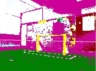
36 Preparation This time, footoffset would be set to the opposite time cycle to a typical straight kick. So when turning right and kicking with the left foot, the walk would continue until footoffset = t = T/2 and vice versa. Once the timing conditions have been met, isturning is set to true with iskicking still at false, haskicked is set to false, turnangle is set from the kickdirection in walkenginerequest and coronalamplitude is set to 13 with the period T set to 0.75 seconds. Turn Step Though the step itself lasts T/2 seconds, the actual turn is executed within the middle 80% so that the turning foot has time to lift and does not drag against the ground. During this time, the hip yaw pitch joint is interpolated from 0 to the turnangle multiplied by a TURN SCALE of 1.25 to compensate for noise and lost energy. Note that the turnangle is half of the actual requested kickdirection from behaviour, as both the left and right hip yaw pitch joints are connected and controlled by the one motor. Once the turn step is finished, iskicking is set to true and T is set to 4 seconds with coronalamplitude set to to The kickdirection within the walkenginerequest is adjusted by subtracting the turn amount so that the Nao can later continue with a normal forward kick. Finally, footoffset is synced back to the actual kicking foot as opposed to the turning foot. In a sense, this Turn Step Phase is an extension of the Preparation phase, as before a normal forward kick the robot would still be stepping anyway, only this time it is controlled within the kick engine. Weight Transfer (Start) Similar to the original Weight Transfer phase of the forward kick, the robot gradually shifts its weight onto the support foot. However, the one difference is that the swing foot is still turned outwards. Thus as the swing foot is lifted during the Weight Transfer, it is also returned to a straight orientation by interpolating the hip yaw pitch joint from turnangle back to 0. Once complete, isturning is set back to false. Note that the Weight Transfer phase lasts for T/4 seconds, however the inwards turn begins halfway through and lasts for T/8 seconds. This is done to ensure that the robot has sufficient time to adjust most of its weight on to its support foot, as the swing foot cannot be turned if it is still on the ground. Figure 4.2 displays these phases and contrasts them to that of a normal forward kick using the left kick as an example. After this point, the Nao continues through the rest of the phases as part of the regular forward kick. Figure 4.3 pictures snapshots of the whole process of the 30


37 kick while it is performed on an actual robot. Figure 4.3 Snapshots of the dynamic omnidirectional kick in motion Kick Adjustments Further improvements were made to the kick for speed and reliability. Regarding speed in particular, the method in which the joints moved from phase to phase could be enhanced. This is currently conducted using a function known as interpolatesmooth, which takes a section of the sine function and stretches it out to the desired length over a given time period [23]. 31
38 Figure 4.4 An example of the interpolate function from -1 to 1 [23] Firstly, since this interpolate function is based on a sine wave, the point of maximum speed and momentum would occur at the middle of the curve. Secondly, the further away the point of interpolation, the faster the interpolation must occur in order to remain within the same period. Thus to speed up the kick, the knee swing was set to interpolate from 30 to -40. Shifting the centre of the sine curve just past x = 0 would cause the foot to contact the ball, which would be located just in front of the foot, at maximum speed. However, to ensure that the leg remained within inverse kinematics and joint limits, the knee pitch was capped at a forward maximum of -10. Now since the knee swing was set separately, unlike the foot s forward or left position which made use of kinematics, the foot would not always remain parallel to the ground. This could cause problems if the robot was leaning slightly, as parts of the foot could scrape against the ground. Another occurrence would be if the ball was slightly too far forward, as during the leg s forward swing, the ankle would tilt up, potentially causing the robot to step on the ball instead of kicking it. All of these would typically cause the robot to fail to kick, fall over, and in particular cause wear to the knee and ankle joints if scraped against the ground. Thus, to balance out the change in knee pitch, new parameters were added: anklepitch: how much to tilt the ankle pitch to compensate for the swinging knee pitch and keep the foot parallel to the ground anklecompliancepercent: scaling factor to tune the degree of adjustment in the ankle pitch 32
39 During the Kick Phase, ankle pitch was interpolated from -5 to 30 but capped at a forward maximum of 5, half of the knee pitch. The added benefit of levelling the ankle was that the kick gained an increased forward reach as it would be able to actually kick the ball, as opposed to step and slip on it, further improving the kick s reliability. The period of many of the phases were also adjusted to be shorter. Perhaps it was due to the more powerful motors of the Nao v4s, but numerous trials found that the kicks could be sped up without losing balance and reliability. Improving the time taken to transition into actually kicking was particularly important, as it meant we would be able to keep control of the ball and move it in optimal directions before opponent robots could get in the way. Table 4.1 displays the changes in phase times for each of the kicks assuming they are at maximum power. Note that these values represent the actual time spent in the phase as opposed to the period of the cycle (T ). The times of 0.25 seconds for the Preparation phases of the normal forward kicks are taken from a typical step period in the walk engine. Phase 2011 Forward Kick 2012 Forward Kick 2012 Omnidirectional Kick Preparation/Turn Step Weight Transfer (Start) Back Phase Kick Phase Follow Through Phase End Phase Weight Transfer (End) Total Table 4.1: Break down of time (s) between all the kick phases Dynamic Adjustments One of the main motivations for the omnidirectional kick was to improve the striker s line ups by removing the need to spend time lining up the foot exactly with the ball position in the desired kick direction. As such, dynamic adjustments were needed to improve the reliability and execution of the kick. A common problem amongst lining up involved taking multiple steps until the middle of the foot lined up with the ball, however this would become subject to the speed and precision of the walk cycle. Thus it was decided that dynamically adapting the foot out to the ball position would be implemented within the kick engine instead. This would prove useful for reducing the number of steps taken before kicking a ball and increasing the kick s sideways reach, which would be particularly beneficial for the omnidirectional turn kicks as they require stricter line ups. In order to incorporate this new 33


40 information, the MotionAdapter class was modified to read in the ball s filtered position from the Localisation section of the Blackboard. It would then be passed down through the DistributedGenerator until it reached the WalkEngine. To keep track of how much the foot should actually move, a new parameter was created: omniside: how much the foot should be moved in the y direction as based on the ball s y position, fed into left/footside parameter The sideways adjustment was applied throughout the start of the kick and up to 90% of the Back Phase. Since the foot needed to be straight by the time it came into contact with the ball for minimal loss of accuracy, this was was the latest time in which the dynamic movement could be added. One issue with runswift s current method of inverse kinematics is that the positions are defined relative to the hip s frame of reference as opposed to the ground s. When the foot is moved out to the side, the hip roll increases to the opposite side to balance out the robot s change in centre of mass. However, due to the nature of the hip roll joint, the kicking leg is rolled slightly upwards as well, causing the foot to be higher relative to the ground (see Figure 4.5). As such, additional parameters separate to inverse kinematics were needed to ensure the kick s success: shoulderrollamplitude: how much to lift the arm over the kicking foot so it does not get in the way anklepitchamplitude: how much lower the ankle should be tilted to compensate for the hip lift and still make contact with the ball, (added on top of the anklepitch parameter) left/hiplean: how much more the hip should shift over the support foot to stay balanced in compensation for the additional changes Figure 4.5 The upwards roll in the hip as a robot goes from standing, to leaning during a kick, then to reaching its leg out further for a ball on the side 34
41 Other external disturbances during games include being pushed by other robots in the middle of a kick, which can happen very often in close tussle situations. This became another opportunity to make use of the newly available body lean to dynamically adjust the tilt of the kick. Depending on the forward angle and sideways angle of the body lean, the Nao could modify the ankle pitch and ankle roll joints respectively. These values would then be compounded with the ankle adjustments as mentioned in the previous section. Similar formulae already existed in the walk engine s balance adjustment, and were simplified down into the negation of a scaled and filtered version of the body lean. They would then be applied to the tilt of the ankle pitch and roll if iskicking was set to true. Thus by dynamically adjusting the ankle pitch and roll and ensuring the foot stayed parallel to the ground, the chances of a successful kick no matter the surrounding circumstances were increased. 4.4 Results Omniside Reach With the addition of the omniside parameter, the robot s foot could be adjusted sideways to kick balls without having to line up directly behind them. However, due to the limit of each of the joints and kinematics calculations, the foot s dynamic side position could only go so far. As such, a reasonable maximum had to be determined to limit the foot s movement and decide how accurately the robot should line up to kick the ball. This maximal distance would also measure how effective this improvement would be at saving line up time. The side reach was dependent on the support leg s knee bend as the lower the hip, the further the foot could reach out while still making contact with the ball. An experiment was set up to measure how far the foot and the ball could move outwards with the Nao still managing to kick the ball straight according to varying knee bends. 5 kicks were performed at each 5 increase in leg bend, starting at 5 to allow the leg at least some movement to begin with. The maximum sideways foot distance as specified in the walk engine and the average measured maximum sideways ball distance are compared in Figure 4.6. Note the sideways foot distance is specified as an offset within the walk engine through the left/footside parameter, with the maximum found by testing the limits of the joints and kinematics. Sideways ball distance is measured as the difference between the location of the centre of the ball if it were placed for an ideal straight line up, to the location of the centre of a ball at the limits of the kick s reach. Unlike the foot, the ball s maximal side distance follows a non-linear trend, which is at first more and then less than the foot s maximal side distance. This is discussed further in the Evaluation in Section
42 Figure 4.6 Reachable foot and ball side distances according to varying leg bends Omnidirectional Accuracy To test the accuracy of the omnidirectional kick, 5 left kicks were performed at increasing intervals of 20. The robot was placed just within the centre circle facing the goals with the ball placed in the middle of the field. It was then told to kick out towards the centre circle at a certain angle, similar to a kick off situation. Since the surface of runswift s SPL field was not always even, the point at which the ball crossed the centre circle line was marked down, as this was before the ball could begin to drift sideways down the field. Accuracy was then measured by comparing the angle in which the ball had travelled to the angle requested by behaviour. Table 4.2 displays the recorded angles in degrees with Figure 4.7 illustrating the average trend and the error in standard deviation. Measured Angle ( ) Requested Angle ( ) Table 4.2: Recorded angles through increasing degrees of the omnidirectional kick 36
43 Figure 4.7 Average measured kick angles and their standard deviation compared to requested kick angles Kick Power To test the improvements in the forward kicks and their effects on the kick power, an experiment similar to White s in 2011 [23] was set up. Note that the power results also apply to the omnidirectional kick as it reuses the forward kick as its base. Five balls were kicked from the centre of the goal box and allowed to roll to a stop. The distance from the centre of the ball at its starting location to the centre of the ball at its final location were then measured. Both the kicks at their half power of 0.5 and full power of 1.0 were compared. The resulting ranges of the kicks are summarised in Table 4.3. There is a noticeable lack of power in the right kick compared to the left kick, and this asymmetry is discussed in Section Range (m) 2012 Range (m) Left Kick Right Kick Table 4.3: Comparison of the range of kick distances from 2011 and 2012 at varying powers 37
44 4.4.4 Simple Striker Test Finally, to test the speed of the new omnidirectional kick in game situations, a simple Striker test was constructed. The Nao was placed at the middle and side of the field facing the centre circle with the coordinates (0, -2000) and a heading of -90. The ball was then placed right in the centre of the field. Time was measured from the point when the Nao entered the centre circle to when the ball crossed the goal line. 5 trials each were performed for the original forward kick, the kick with dynamic side reach, and finally the complete dynamic omnidirectional kick with turn step included. Table 4.4 displays the recorded times, with Figure 4.8 comparing the average time and standard deviation for each kick. Original Forward Kick Dynamic Forward Kick Dynamic Omnidirectional Kick Trial 1 9.5s 9.4s 9.0s Trial s 8.8s 8.7s Trial 3 9.3s 9.2s 8.8s Trial s 10.2s 8.9s Trial s 8.5s 8.7s Table 4.4: Recorded times from the centre circle across the progress in kicks Figure 4.8 Comparison of average kick times and their standard deviation across the different improvements in kicks 38
45 4.5 Evaluation With runswift s current method of kinematics for leg positions, the ankle joint, and hence the foot, was able to move a reasonable distance outwards from its typical straight kicking position. Since the foot is approximately 80mm wide, with the flattest area at the front being approximately 45mm wide, it was still able to connect with balls that were slightly further away than the position of the actual ankle joint. As the start of the graph in Figure 4.6 shows, the ball can be placed up to 20mm further to the side of the specified foot position and still be kicked. However, the ball s side distance eventually plateaus at a maximum of around 110mm. As mentioned earlier in Section 4.3.3, due to the nature of the frame of reference in which kinematics is calculated, the further the foot is placed outwards, the more hip lean required. But instead of simply moving to one side, the hip joint began to roll upwards, causing the foot to rotate upwards as well. This ankle roll can actually be observed in the last frame of Figure 4.5. By the end of the graph, the ankle roll joint had reached its maximum, meaning the foot was no longer parallel to the ground and no longer had its wide contact area. At this point, only the very tip of the inside edge of the foot could still make contact with the ball. Thus the maximum knee bend worth pursuing to attain the robot s side reach of 110mm was at 20. Although other methods of moving the knees and feet might provide better side reach results, the reason for this approach and the decision for the eventual leg bend took into account multiple factors. Mainly, many of these methods and parameters overlap with those used in the walk. The knee bend in particular is a crucial parameter, with a requirement that both legs have the same bend for a symmetrical and stable walk. There is also a trade off in that a lower bend results in a faster walk but applies increasing amounts of stress on the robot s knees. The knee bend for kicks and walks should not differ significantly, as large changes in knee bend, especially while rocking, can throw the robot off balance. Additionally, if the knee is already quite bent, there is less swing available when performing the kick, causing it to lose potential power. Finally, even if a low leg bend was chosen for a further side reach, the greater the shift in the foot s side position, the less stable and unreliable the kick became. As such the final chosen leg bend ranged from 16-25, which reflected the range in speeds in which the walk could perform at. Since the walk would slow down just before kicking, the actual leg bend used in kicks were typically around the lower range towards 16. The dynamic addition of side reach would prove particularly useful as a contributing factor to the success of the turn step and omnidirectional kick. The larger the turn angle, the further to the side the ball would be after the turn. Hence without the omniside component, it was possible for the omnidirectional turn kick to connect using the side of the foot instead, 39
46 or in the worst case, it would miss all together. As section of the results show, the final omnidirectional kick actually had quite a reasonable success rate with fair accuracy up until 65. The slight but consistent bias towards the right up until around 40 suggests that the dynamic side offset in the foot is tuned too far outwards. This would cause the ball to connect on the inside of the left foot and travel more towards the right. However, the bias towards the left on the 60 kick suggests other factors are involved. It is likely that the TURN SCALE used to exact the turn step should not be a simple constant, but adjusted less for smaller angles and more for larger angles. Once past about 65 though, the omnidirectional kick becomes ineffective. As shown in the results from the 5 trials for the 80 kick, 2 of them are nonexistent due to the kick s instability and failure to complete. It seemed that 80 was too wide a turn for the Nao to complete within a single step as well as the period and coronal rock constraints. Out of the 3 kicks that successfully completed, all were subject to the same instabilities that caused their turn step to land earlier than anticipated. While this did prevent the robot from falling over like the 2 failed trials, it also meant that the turn was cut short, hence the resulting degree of 65. The next measure of the new kick s success was how powerful it could be. All the kick adjustments proved their worth, with the 2012 left kick surpassing the 2011 left kick by m and being able to consistently kick a ball almost the length of a field, if not past it. If it were not for the uneven surfaces in the field and the loss of energy in rolling sideways down the field, the minimum kick range would be even higher. Also, since runswift s SPL field ended at approximately 6.5 metres, the last sections involved the ball losing energy by rolling off the edge of the field and on to bouncier carpet. Hence, the actual maximum kick range also had the potential to be even higher. While the 2012 right kick did surpass the 2011 right kick by m, it was still significantly weaker than the left kick. Although the exact reasons are unknown, it is suspected that the mass differences and asymmetry in the Nao would play a part. In fact, without the dynamic body lean adjustments, the right kick was unable to perform at a full power of 1.0 as the foot would keep kicking into the ground. This suggests that there might also be issues with asymmetry in the left and right side motors, which seem to either produce more noise or are unable to keep up with the speed of the left. Overall the new dynamic omnidirectional kick has been a success and quite an improvement over last year s methods. As Figure 4.8 shows, adding the dynamic adjustments such as the side reach improved scoring time by just under a second on average. Combining the turn step on top of that reduced the average time by around a further half a second. It was particularly effective with the robot s approach from the side of the field as the method in which we walk and turn around the ball to face the right direction allowed for smooth 40
47 transitions into the turn step. Although the total time of the dynamic omnidirectional kick was not always faster, it was more consistent, with all 5 trials reliably scoring goals within 9 seconds. This kind of reliability is essential as it contributes to ensuring victory in actual matches, even during high pressure situations. However, it is important to note that the line up and times are heavily influenced by the other modules in the runswift code. For example, fluctuations in vision quality and localisation accuracy can contribute to the speed of the line up and precision in kicking the ball. 41
48 Chapter 5 Dribble Kick Engine Governed by the currentactiontype being DRIBBLE, the dribble engine sits as a subset within the kick engine, which itself is a subset of the walk engine, with similar parameters and phases. Similar to a regular kick, a dribble kick is another predefined movement aimed at keeping the ball moving around the field. Its main purpose is to supplement the robot s movements with a kick focused on speed and manoeuvrability at the cost of power and accuracy. This is particularly important in situations where opponent robots are nearby and contesting the possession of the ball. Speed is of the essence, as the first robot to nudge the ball away will typically gain the advantage. Once again, focus will be applied to the forward dribbles as opposed to the side dribbles. 5.1 Background Dribble Parameters As it was in 2011 [23], many of the parameters used by the dribble engine were shared amongst the kick engine. However, a few additional variables were used to help keep track of the dribble state: hasdribbled: set to true after finishing a dribble lastdribbletime: set upon finishing a dribble Dribble Phases Similarly in 2011 [23], the dribble kick phases were as follows: 42
49 Preparation In a similar fashion to a kick request, once a dribble request is received it is saved into the walkenginerequest. Once the correct support foot has landed, currentactiontype is set to DRIBBLE, hasdribbled is set to false and the period T is set to 1.4 seconds with coronalamplitude set to 20. Kick Phase The Kick Phase encompasses what would be a typical Weight Transfer (Start) Phase, as the kick motion simply occurs through a slightly longer period of the walk cycle. During this phase, the foot is interpolated forward to 70mm over 0.7 seconds. End Phase The foot is return to its original state by interpolating backwards to 0mm over 0.7 seconds. As soon as the phase is complete, hasdribbled is set to true. This then triggers what would typically encompass a typical Weight Transfer (End) Phase, as the parameters are set back for normal walking. In particular, this involved setting lastdribbletime to 0, returning currentactiontype, T and coronalamplitude to their normal walk values and updating t to reflect the current foot cycle. 5.2 Forward Dribble Kicks Kick Adjustments Like the forward kicks, it was found that many of the phases and parameters could be tuned for increased speed and power. More specifically, the period T was decreased to 1.2 seconds, with the coronalamplitude adjusted to 13.5 accordingly. The foot s interpolated forward position was also increased from 70mm to 95mm during this time. For an even faster impact, a similar approach from the forward kick was applied to shift the peak of the interpolation sine wave forward towards the point of contact with the ball. This was done by interpolating the foot s forward position 25mm past the desired position, then capping the final value to retain stability. 43
50 5.2.2 Dynamic Adjustments To improve the line up speed for dribbles, the omniside parameter was used as a dynamic adjustment once again. Like the forward kicks, it allowed the foot to adjust sideways depending on the ball location. However, since the forward dribble period was much shorter, there was not nearly as much time to adjust the foot. In fact, the side reach was only adjusted during the first 20% of the dribble in order to contact the ball at a straight and consistent angle. The leg bend was also typically less than it would be during normal kicks due to the dribbles being able to occur mid-walk. As such, the side reach was not particularly far, but considering that accuracy was not as paramount in dribbles, it was still faster than no dynamic adjustments at all Walk and Dribble Integration - the Forward Shuffle While the current dribbles are faster than the kicks when it comes to nudging the ball away from opponents, they are still nothing like a human s. Ideally, the robot should be able to move with the ball and continue chasing after it. Rather than interpolating the foot back to a position of 0mm, it should use its momentum and stride to keep taking a step. A sideways shuffle was attempted by White in 2011 [23], which involved sidestepping with one foot in front of the other. However, it was unstable and was never perfected for competition. Instead, a new approach of using both the PlannedWalkGenerator and the WalkEngine to better integrate walking and dribbling was devised in A new forward shuffle was thus created to follow a ball forward, both dribbling and stepping at the same time. While simply walking into the ball would be ideal, inaccuracies could result from contacting the ball with different edges of the foot. Depending on which part of the step cycle the robot was in, it could also produce unreliable power. As such, the robot was made to roughly line up to the ball first from within behaviour. The shuffle dribble was then called upon using the isfast parameter, which was originally only used for turning on the Fast Walk in the walk engine. Eventually this information was passed down through to the PlannedWalkGenerator, which is where the walk s steps are actually controlled and planned out. Forward and backward movement during the walk is typically applied when the robot is in between steps, so this timing was reused for the forward shuffle. At this point, the PlannedWalkGenerator would set the relevant parameters in its child WalkEngine. Namely, currentactiontype would be set to DRIBBLE and hasdribbled would be set to false like a normal dribble. However, instead of manipulating the joints or feet position directly, the walk parameters forwardl and forwardr within the walk request were set to 65mm. 44

51 Figure 5.1 Changes in key parameters during a shuffle, with blue representing the current dribble kick phase and green representing the controlling class Control would then fall to WalkEngine, where although the currentactiontype was set to DRIBBLE, the isfast parameter was used to make sure all the walk cycle functions were still applied. Based on the requested foot, it would ensure that the correct phase and subsequent footoffset was in place. Meanwhile, the previously set walk parameters would automatically ensure that the foot would take the appropriate forward step during this phase. Once a time of T/2 had passed and the phase was complete, the robot would continue walking as normal with the relevant dribble engine parameters returned to their previous state. currentactiontype was returned to WALK, hasdribbled to false, with lastdribbletime being reset to 0. The flow of these states are pictured in Figure 5.1. Unlike the other dribbles and kicks, there was no need to change the period or coronal rock as the shuffle would smoothly continue as part of the walk. The walk cycle and its support phases are shown once again in Figure 5.2, with slight modifications to the leg movements to display the integration of the shuffle. As an example, dribbling the ball with the right foot occurs during the exact same time as a normal left support phase in the walk, with the swinging right foot being extended more forward than usual. Figure 5.2 An example of the shuffle s timing within the walk cycle 45
52 5.3 Results Unlike the forward kicks, the ideal qualities in a dribble are not accuracy or power, but speed and versatility. However, these can vary greatly depending on the occasion and the strength of the opposing team. As such, the results described in this section are based on the tussles that occurred during actual competition matches from Robocup In the early matches, runswift s dribbles managed to win all close tussles and keep the ball moving away from nearby opponent robots. This was particularly showcased when runswift stole the ball away with a forward shuffle in a defensive kick off at 5:06 in the match against the Dutch Nao Team, and dodged through all 3 of TJArk s robots with 2 forward shuffles in a defensive kick off at 10:44. Another successful case was the goal against the Austrian Kangaroos at 6:52, where a forward shuffle was used to quickly knock the ball in right next to the goalie. However against stronger teams with fast dribbles of their own, the outcome was not always favourable. Close tussles against teams such as B-Human and Austin Villa involved at least 2 dribbles before the ball would pop out towards the side, with both robots chasing the ball only to ensue yet another tussle. Although runswift s dribbles were still sometimes effective, such as at 13:14 against HTWK in the third place play-offs, their goal was scored by surging past all four of runswift s robots with their strategy of constantly dribbling. It was however found that the forward shuffle as opposed to the forward dribble was not ideal for the goalie. There was an occasion were the goalie performed the forward shuffle to avoid an incoming opponent, and then continued dribbling onwards past the other robots. Instead of stepping forward to chase the ball, the goalie should simply clear it and be able to return to a defensive position if need be. As such, the behaviours were modified using the isgoalie flag to separate the use of the forward dribble in the goalie and the forward shuffle in the striker. 5.4 Evaluation The dribbles were a useful addition to the runswift arsenal, with ball possession being retained throughout most of the early matches, even during defensive kick offs. Many of runswift s high scoring matches of 10-0 and multiple fast goals of less than 20 seconds would not have been possible without their speed and manoeuvrability. They were also on a competitive level with the more advanced teams, as evidenced by the close games against B-Human and Austin Villa. The forward shuffle proved useful not just for nudging the ball away, but for continuing after it in order to retain possession of the ball. However, the most effective direction in which to dodge an opponent is not necessarily always 46
53 forward. The lack of a side shuffle meant that runswift s robots did not have as much sideways agility. Even if the forward shuffle managed to nudge the ball past an opponent, the striker robot itself would need to pass the opponent to continue kicking the ball and avoid being caught for pushing. A sideways shuffle, on the other hand, would be much more effective for allowing the striker to dodge past as well. Unfortunately, development on such a manoeuvre was begun but not polished in time for competition. 47
54 Chapter 6 Pos Actions While the more complicated motions of walking and kicking had their own engine, other actions, such as standing and getting up for example, were simply governed by a series of joint angles. If behaviour requested one of these actions, the DistributedGenerator would send the request down to the ActionGenerator, which would then refer to the file for the relevant action. The basic structure of such a file, known as a.pos file, was created in 2010 [16] and would contain entries, each consisting of the angles for each joint in degrees. This would then be followed by the duration of that particular movement in milliseconds and the end of the line. In 2011 [23], this was expanded upon to include an additional optional line for controlling the motor stiffness in each of the joints. 6.1 Front Getup Routine Being able to get up is a very important skill for a soccer robot, especially since instabilities in bipedal motion mean they are highly susceptible to falling over. A fallen robot would be unable to kick the ball and could even obstruct team members from getting to the ball due to the amount of space required to perform the getup routine. Removal penalties would also be applied if the robot continuously proved unable to get up or pushed other robots in the process of attempting the getup [29]. Since getup routines are defined as set actions in.pos files, care must be taken to program the joints with the appropriate momentum to shift the robot s centre of mass off the ground and back to a standing stance. This chapter focuses on the improvements made within the front getup routines in particular. For work on other actions such as the back getup, refer to Liu [24]. 48

 Modified")


55 6.1.1 Arm Swing Figure 6.1 Snapshots of the movement of the outward versus inward arm swings (a) Original outward arm swing (c) Modified inward arm swing The main drive behind the front getup routine is the sliding of the arms in towards the body for backwards momentum and extending them off the ground to give the upper body more lift. Since the state in which a robot falls is unknown, the first step of the getup routine is to realign the body straight on the ground with its arms by its side. Next is to swing the arms around and up above the head to begin the sliding motion. Now the problem with this is that by the nature of the shoulder joints, the arms must be fully extended in order to be swung upwards from the side of the body. This ends up taking up a lot of space, with the potential for the arms to knock against some object and interrupt the getup routine, thus causing the robot to fail at getting up. In the worst case, the robot s swinging arms could push over robots nearby, resulting in a pushing penalty. By manipulating the arm joints to swing the arms inwards and underneath the torso, these space issues would be drastically 49
56 reduced. As such, the robot would instead be able to get up more reliably in much more confined spaces. This would prove critical in close tussles with multiple robots, especially since such situations would often cause at least one robot to fall. A comparison of the original and modified arm swing movements are displayed in Figure Results The final arm swing method was tuned till the robot could get up for 10 times in a row. Once finalised, it was compared to the original by measuring the differences in arm lengths and the area used. It was found that moving an arm inwards as opposed to having it outstretched to the side took up 23cm less space. Thus, the new arm swing brought the total saved space beside the robot to 46cm. Since the arms were no longer extended above the robot s head either, this saved another 12cm in the forwards direction. Along with a smoother combination of some of the latter standing steps, the whole getup routine had also decreased from 5480 to 4500 milliseconds. Table 6.1 describes the number of attempts at a getup before the robot successfully stood up. The column Removed counts the getups that were never given a chance to complete due to being penalised and removed from the field. These results are tallied according to each of runswift s matches in Mexico City during Robocup Number of Attempts Match Removed 1 - Robocanes Dutch Nao team B-Human Austrian Kangaroos TJArk UPennalizers Austin Villa Nao-Team HTWK Total Table 6.1: Attempts per forward getup across runswift s games during Robocup
57 6.3 Evaluation Considering the ideal qualities of a getup routine are speed and reliability, the new front getup performed very well in testing. In game situations, the decrease in area taken up by the outwards arm swing was crucial in enabling the robots to get up in confined areas. As Table 6.1 has shown, the majority of the front getups ended in success. In fact, an added benefit was found when a robot fell on top of the ball in Game 6 against UPennalizers. While getting up, the new arm swing managed to sweep the ball out from under the robot and avoid the ball holding penalty. The increase in the amount of getups towards the middle of the competition reflect the increase in competition, with more robots on the field being aggressive around the ball and poor networking causing failures in team communication. The increase in attempts required as well as subsequent failures can also be attributed to robots getting worn out from continuous matches. Many of the repeat attempts and one of the removals were due to incomplete shoulder motor actuation. In total, the 4 removals were caused by the robots being penalised twice for fallen robot, once for pushing, and once for ball holding. The following decrease in front getups were due to the walk being slowed down in an attempt to reduce the risk of pushing and falling down, as well as a significant improvement in wireless networking and team communication. However, much work remains to be done as robots were still subject to falling over mid-getup. One of the main issues of the front getup was its heavy reliance on the Nao s arms. The more the robot was made to perform the getup, the more the shoulder motors became worn out. In fact, many of the failed getups were a result of one of the robot s having an erratic shoulder pitch motor. A possible solution would be to move away from applying such stress on the arms and to instead make more use of the legs and swinging momentum to get up. Another problem was the static nature of the getup routine, as the joints are moved through a set series of positions as opposed to a dynamic generator. While the use of a.pos file is a simple and clear solution, it does not allow for any adjustments to external disturbances such as pushing or resistance from nearby obstacles. Additionally, every robot differs slightly in their manufacturing, so perfectly tuning a.pos file for one robot could become moot on another. 51
58 Chapter 7 Striker Behaviour The culmination of all the improvements would ultimately be tested in runswift s striker, which was defined as the robot set to attack the ball and was typically the closest as well. This behaviour was an opportune chance to apply the new kicks and speedier line up techniques. The main purpose of the striker behaviour was to score goals, or at least kick the ball away from opponents, as quickly and reliably as possible. However, since the goalie could sometimes become the robot in charge of attacking the ball, the lower level behaviour of kicking a ball was abstracted into a state machine in the class known as Shoot. Final actions were then controlled or overrided by the higher level decision tree in the Striker class. 7.1 Low Level State Machine - Shoot The main aim of this behaviour was to kick the ball into the goal, and the following points list the Shoot specific states required to carry out such a task: GoToBall: uses WalkToPoint [30] to aim for a point just behind the ball in the x direction, with a slight bias to the right in order to line up with the left foot WalkAroundBall: if approaching the ball from the opposite goal direction, turn and step around the ball while still facing it until kicking into the opponent s goal is possible LineUp: once the robot is close enough to the ball, it lines up in front of the ball with its foot in position for a straight kick then sets up parameters for KickBall LineUpSlightAngle: a subclass of LineUp but for omnidirectional kicks with a relatively small angle 52
59 LineUpWideAngle: a subclass of LineUp but for omnidirectional kicks with a relatively wide angle LineUpDribble: lines up the robot in front of the ball for either forward or side dribbles and shuffles KickBall: performs the actual kick or dribble according to the given parameters and ensures the kick completion before continuing to chase the ball Tasks common to other behaviours were also used by simply calling upon externally written skills. These non-striker specific states are summarised as follows: LostScan: stands still and performs a wide scan, only used if the robot is totally lost [31] which typically occurs after returning from a penalty SearchBall: pans the head in search of the ball, occasionally turning the body if need be [30] There are also many parameters used to keep track of the robot s actions, including: isrelative: boolean set by higher level behaviours (such as Striker) for interrupting normal kick flow with higher priority dribbles targetdir/angledir: the angle from the robot to the goal direction at the ball kickaim: used to aim kicks either around a goalie, or in an absolute direction during kick offs useleft: whether or not the left foot should be used to perform the kick strict: whether or not the robot should line up more strictly during dribbles as opposed to just kicking in a relative direction absdir: the angle at which the robot should strictly line up to kickdir: the robot relative direction of the kick for use in the walk engine kickfoot: sets the foot type of LEFT or RIGHT kicktype: sets the action type of KICK or DRIBBLE power: strength, ranging from 0.0 to 1.0, at which the robot should kick at 53

60 The general flow of Shoot s states are shown in Figure 7.1, with rectangles representing Shoot specific states and ellipses representing states of external origin. GoToBall is the main entry point of the states, however it must first establish its location as well as that of the ball before it can proceed with its main task. Once close enough to the ball, the robot proceeds into either one of the LineUpDribble or LineUp states and its children. Control can also pass to LineUpDribble even if the robot is amidst one of the LineUp states as long as the high priority parameter isrelative is set. Finally, after kicking the ball, the cycle continues with the robot returning to the GoToBall state. Figure 7.1 Key flow between states in the Shoot behaviour Penalty Shoot-out States In the case of a tie, it was possible for the match outcome to be determined by a penalty shoot-out [29]. Since the main aim was to kick the ball into the goal yet again, Shoot was used as the underlying class. runswift s strategy was to first dribble the ball closer to the goals, 54
Humanoid Omni-directional Locomotion. Thesis B Report
 Humanoid Omni-directional Locomotion Thesis B Report Brock White October 10, 2011 School of Computer Science & Engineering University of New South Wales Sydney 2052, Australia Supervisors and Assessors
Ranger Walking Initiation Stephanie Schneider 5/15/2012 Final Report for Cornell Ranger Research
 1 Ranger Walking Initiation Stephanie Schneider sns74@cornell.edu 5/15/2012 Final Report for Cornell Ranger Research Abstract I joined the Biorobotics Lab this semester to gain experience with an application
Humanoid Robots and biped locomotion. Contact: Egidio Falotico
 Humanoid Robots and biped locomotion Contact: Egidio Falotico e.falotico@sssup.it Outline What is a Humanoid? Why Develop Humanoids? Challenges in Humanoid robotics Active vs Passive Locomotion Active
ZIPWAKE DYNAMIC TRIM CONTROL SYSTEM OUTLINE OF OPERATING PRINCIPLES BEHIND THE AUTOMATIC MOTION CONTROL FEATURES
 ZIPWAKE DYNAMIC TRIM CONTROL SYSTEM OUTLINE OF OPERATING PRINCIPLES BEHIND THE AUTOMATIC MOTION CONTROL FEATURES TABLE OF CONTENTS 1 INTRODUCTION 3 2 SYSTEM COMPONENTS 3 3 PITCH AND ROLL ANGLES 4 4 AUTOMATIC
THE UNIVERSITY OF NEW SOUTH WALES SCHOOL OF COMPUTER SCIENCE AND ENGINEERING. Walking Nao. Omnidirectional Bipedal Locomotion
 THE UNIVERSITY OF NEW SOUTH WALES SCHOOL OF COMPUTER SCIENCE AND ENGINEERING Walking Nao Omnidirectional Bipedal Locomotion Aaron James Soon Beng Tay Bachelor of Science (Computer Science, Honours) August
SKILL ANALYSIS SAMPLE F
 SKILL ANALYSIS SAMPLE F MOTOR SKILL: SOCCER SHOT (BALL STATIONARY) Aim/Purpose: The aim of this experiment is to record and analyse the movement process and technique required when kicking a soccer ball
ZMP Trajectory Generation for Reduced Trunk Motions of Biped Robots
 ZMP Trajectory Generation for Reduced Trunk Motions of Biped Robots Jong H. Park School of Mechanical Engineering Hanyang University Seoul, 33-79, Korea email:jong.park@ieee.org Yong K. Rhee School of
Putting Report Details: Key and Diagrams: This section provides a visual diagram of the. information is saved in the client s database
 Quintic Putting Report Information Guide Putting Report Details: Enter personal details of the client or individual who is being analysed; name, email address, date, mass, height and handicap. This information
 Kochi University of Technology Aca Study on Dynamic Analysis and Wea Title stem for Golf Swing Author(s) LI, Zhiwei Citation 高知工科大学, 博士論文. Date of 2015-03 issue URL http://hdl.handle.net/10173/1281 Rights
Body Stabilization of PDW toward Humanoid Walking
 Body Stabilization of PDW toward Humanoid Walking Masaki Haruna, Masaki Ogino, Koh Hosoda, Minoru Asada Dept. of Adaptive Machine Systems, Osaka University, Suita, Osaka, 565-0871, Japan ABSTRACT Passive
the world s most advanced humanoid robot
 the world s most advanced humanoid robot 02 : ASIMO V2 : TECHNICAL GUIDE : ROBOT DEVELOPMENT : CONTENTS ROBOT DEVELOPMENT 3 HISTORY OF HUMANOIDS 5 ASIMO v1 7 ASIMO v2 16 THE FUTURE 18 Creating New Mobility
COACHES SESSION PLAN Skill Presented: Clear and Drive
 and COACHES SESSION PLAN Skill Presented: and STEP 1: EXPLANATION AND DEMONSTRATION A player uses a clear to move out of the area of play and create space for another player, and drives when space is created
Design of a double quadruped for the Tech United soccer robot
 Design of a double quadruped for the Tech United soccer robot M.J. Naber (0571509) DCT report number: 2009.134 Master Open Space project Eindhoven, 21 December 2009 Supervisor dr.ir. P.C.J.N. Rosielle
Dynamically stepping over large obstacle utilizing PSO optimization in the B4LC system
 1 Dynamically stepping over large obstacle utilizing PSO optimization in the B4LC system QI LIU, JIE ZHAO, KARSTEN BERNS Robotics Research Lab, University of Kaiserslautern, Kaiserslautern, 67655, Germany
Motion Control of a Bipedal Walking Robot
 Motion Control of a Bipedal Walking Robot Lai Wei Ying, Tang Howe Hing, Mohamed bin Hussein Faculty of Mechanical Engineering Universiti Teknologi Malaysia, 81310 UTM Skudai, Johor, Malaysia. Wylai2@live.my
ZSTT Team Description Paper for Humanoid size League of Robocup 2017
 Adult- ZSTT Team Description Paper for Humanoid size League of Robocup 2017 Jaesik Jeong, Youngsup Oh and Jeehyun Yang ZSTT E-mail: soulmatree@gmail.com Web: www.soulmatree.com Abstract. This paper describes
RoboCup SPL 2015 Champion Team Paper
 RoboCup SPL 2015 Champion Team Paper Brad Hall, Sean Harris, Bernhard Hengst, Roger Liu, Kenneth Ng, Maurice Pagnucco, Luke Pearson, Claude Sammut, and Peter Schmidt School of Computer Science and Engineering
Dynamic Positioning Control Augmentation for Jack-up Vessels
 DYNAMIC POSITIONING CONFERENCE October 9-10, 2012 Design and Control Session Dynamic Positioning Control Augmentation for Jack-up Vessels By Bradley Deghuee L-3 Communications 1 Introduction Specialized
Coaching the Triple Jump Boo Schexnayder
 I. Understanding the Event A. The Run and Its Purpose B. Hip Undulation and the Phases C. Making the Connection II. III. IV. The Approach Run A. Phases B. Technical Features 1. Posture 2. Progressive Body
A new AI benchmark. Soccer without Reason Computer Vision and Control for Soccer Playing Robots. Dr. Raul Rojas
 Soccer without Reason Computer Vision and Control for Soccer Playing Robots Dr. Raul Rojas A new AI benchmark -computer vision in real time - embodied intelligence: mechanics - energy management - local
Line Following with RobotC Page 1
 Line Following with RobotC Page 1 Line Following with By Michael David Lawton Introduction Line following is perhaps the best way available to VEX Robotics teams to quickly and reliably get to a certain
Kungl Tekniska Högskolan
 Centre for Autonomous Systems Kungl Tekniska Högskolan hic@kth.se March 22, 2006 Outline Wheel The overall system layout : those found in nature found in nature Difficult to imitate technically Technical
Centre for Autonomous Systems
 Centre for Autonomous Systems Kungl Tekniska Högskolan hic@kth.se March 22, 2006 Outline Wheel The overall system layout : those found in nature found in nature Difficult to imitate technically Technical
Biomechanics and Models of Locomotion
 Physics-Based Models for People Tracking: Biomechanics and Models of Locomotion Marcus Brubaker 1 Leonid Sigal 1,2 David J Fleet 1 1 University of Toronto 2 Disney Research, Pittsburgh Biomechanics Biomechanics
Robocup 2010 Version 1 Storyboard Prototype 13 th October 2009 Bernhard Hengst
 Robocup 2010 Version 1 Storyboard Prototype 13 th October 2009 Bernhard Hengst Developmental Research Strategy! Fail-fast, fail cheap! We should accept poor performance but insist it is complete! Version
Sample Solution for Problem 1.a
 Sample Solution for Problem 1.a 1 Inverted Pendulum Model (IPM) 1.1 Equations of Motion and Ground Reaction Forces Figure 1: Scheme of the Inverted Pendulum Model (IPM). The equations of motion of this
Opleiding Informatica
 Opleiding Informatica Determining Good Tactics for a Football Game using Raw Positional Data Davey Verhoef Supervisors: Arno Knobbe Rens Meerhoff BACHELOR THESIS Leiden Institute of Advanced Computer Science
PERCEPTIVE ROBOT MOVING IN 3D WORLD. D.E- Okhotsimsky, A.K. Platonov USSR
 PERCEPTIVE ROBOT MOVING IN 3D WORLD D.E- Okhotsimsky, A.K. Platonov USSR Abstract. This paper reflects the state of development of multilevel control algorithms for a six-legged mobile robot. The robot
 AGE GROUP/PROGRAM: U14 TOWN WEEK # 1 THEME: AWARENESS/ARGENTINA Improve 1 st touch Speed of play Playing with the head up CORE GAME 1: PASSING LONG & SHORT 15 X 15 YARD AREA Switch the play Players on
PARA-BADMINTON WHEELCHAIR DEVELOPMENT
 PARA-BADMINTON WHEELCHAIR DEVELOPMENT Para-Badminton Wheelchair Development Introduction The use of the arms for both movement and hitting technique are the main challenges in the wheelchair sports class.
Policy Gradient RL to learn fast walk
 Policy Gradient RL to learn fast walk Goal: Enable an Aibo to walk as fast as possible Policy Gradient RL to learn fast walk Goal: Enable an Aibo to walk as fast as possible Start with a parameterized
AGE GROUP/PROGRAM: U14 TOWN WEEK # 1
 AGE GROUP/PROGRAM: U14 TOWN WEEK # 1 THEME: AWARENESS/ARGENTINA Improve 1 st touch Speed of play Playing with the head up Players on their toes, balanced and communicating. Good 1st touch out of the body
Robotics and Autonomous Systems
 Robotics and Autonomous Systems Lecture 4: Locomotion Richard Williams Department of Computer Science University of Liverpool 1 / 57 Today 2 / 57 Motion Two aspects: Locomotion Kinematics Locomotion: What
beestanbul RoboCup 3D Simulation League Team Description Paper 2012
 beestanbul RoboCup 3D Simulation League Team Description Paper 2012 Baris Demirdelen, Berkay Toku, Onuralp Ulusoy, Tuna Sonmez, Kubra Ayvaz, Elif Senyurek, and Sanem Sariel-Talay Artificial Intelligence
Gait Analyser. Description of Walking Performance
 Gait Analyser Description of Walking Performance This brochure will help you to understand clearly the parameters described in the report of the Gait Analyser, provide you with tips to implement the walking
CONFIRMATION OF PHD CANDIDATURE DAMIEN KEE 2003
 CONFIRMATION OF PHD CANDIDATURE DAMIEN KEE 2003 List of Publications: Wyeth G, Kee D, Yik T, Evolving a Locus based Gait for a Humanoid Robot, Proceedings of the International Conference on Intelligent
Sensing and Modeling of Terrain Features using Crawling Robots
 Czech Technical University in Prague Sensing and Modeling of Terrain Features using Crawling Robots Jakub Mrva 1 Faculty of Electrical Engineering Agent Technology Center Computational Robotics Laboratory
 Age Group/Program: U14 Town Week # 1 Theme: Awareness/argentina Session Goals: Coaching Points: Understand Your Audience: Improve 1 st touch Speed of play Playing with the head up Players on their toes,
Structure (Down plane)
") By Lauren Russell Structure (Down plane) The body (toes, knees, hips, wrists and shoulders) is aligned parallel to the intended target line. The torso is tilted over the ball from the hips whilst maintaining
By Lauren Russell Structure (Down plane) The body (toes, knees, hips, wrists and shoulders) is aligned parallel to the intended target line. The torso is tilted over the ball from the hips whilst maintaining
Outline. Newton's laws of motion What is speed? The technical and physical demands of speed Speed training parameters Rugby specific speed training
 Linear speed Outline Newton's laws of motion What is speed? The technical and physical demands of speed Speed training parameters Rugby specific speed training Outline Session structure Teaching guidelines
Robot motion by simultaneously wheel and leg propulsion
 Robot motion by simultaneously wheel and leg propulsion Aarne Halme, Ilkka Leppänen, Miso Montonen, Sami Ylönen Automation Technology Laboratory Helsinki University of Technology PL 5400, 02015 HUT, Finland
Robotics and Autonomous Systems
 Robotics and Autonomous Systems Lecture 4: Locomotion Simon Parsons Department of Computer Science University of Liverpool 1 / 57 Today 2 / 57 Motion Two aspects: Locomotion Kinematics Locomotion: What
Coaching Principles. 1. Introduce 2. Demonstrate 3. Explain 4. Organize 5. Execute 6. Correct 7. Practice
 5 Pin Bowling Drill Book Updated August 2008 Coaching Principles STEPS IN TEACHING A DRILL 1. Introduce 2. Demonstrate 3. Explain 4. Organize 5. Execute 6. Correct 7. Practice GENERAL PRINCIPLES Drills
UNDER 9 AND UNDER 12 PLAYER EVALUATION (fundamental and developmental stages)
") UNDER 9 AND UNDER 12 PLAYER EVALUATION (fundamental and developmental stages) PLAYER S NAME: CLUB: E-MAIL: PHONE: GENDER: BIRTHDAY: MONTH YEAR PLAYING HAND: BACKHAND: PROGRAM: COACH S NAME: E-MAIL: PHONE:
UNDER 9 AND UNDER 12 PLAYER EVALUATION (fundamental and developmental stages) PLAYER S NAME: CLUB: E-MAIL: PHONE: GENDER: BIRTHDAY: MONTH YEAR PLAYING HAND: BACKHAND: PROGRAM: COACH S NAME: E-MAIL: PHONE:
intended velocity ( u k arm movements
 Fig. A Complete Brain-Machine Interface B Human Subjects Closed-Loop Simulator ensemble action potentials (n k ) ensemble action potentials (n k ) primary motor cortex simulated primary motor cortex neuroprosthetic
DP Ice Model Test of Arctic Drillship
 Author s Name Name of the Paper Session DYNAMIC POSITIONING CONFERENCE October 11-12, 211 ICE TESTING SESSION DP Ice Model Test of Arctic Drillship Torbjørn Hals Kongsberg Maritime, Kongsberg, Norway Fredrik
Application Block Library Fan Control Optimization
 Application Block Library Fan Control Optimization About This Document This document gives general description and guidelines for wide range fan operation optimisation. Optimisation of the fan operation
PHYSICAL EDUCATION PERFORMANCE ASSESSMENT SUPPORT MATERIAL CRICKET
 PHYSICAL EDUCATION PERFORMANCE ASSESSMENT SUPPORT MATERIAL CRICKET IMPORTANT INFORMATION School Curriculum and Standards Authority, 2017 This document apart from any third party copyright material contained
Chesapeake Region Volleyball Beach High Performance Program
 Chesapeake Region Volleyball Beach High Performance Program Beach Coaching Training Guide This document was based on USAV Beach-HP, BCAP, and National Team Training and will be used to standardize beach
Spring 2010 Coaching Sessions U14
 Spring 2010 Coaching Sessions U14 Coaching Ages 13 to 14 Years This section provides you with a eight week training program for children ages 13 through 14 years. Each practice features four fun and progressive
14 The Divine Art of Hovering
 14 The Divine Art of Hovering INTRODUCTION Having learned the fundamentals of controlling the helicopter in forward flight, the next step is hovering. To the Hover! In many schools, hovering is one of
Basic organization of the training field
 Burke Athletic Club u4 & 5 Training Scheme Phase I Introduction to Soccer 1v1 Legend The purpose of this training program is to allow the u4 and 5 s the opportunity to learn some basic ideas and experience
EUROPEAN NEW CAR ASSESSMENT PROGRAMME (Euro NCAP) SLED TEST PROCEDURE FOR ASSESSING KNEE IMPACT AREAS
 SLED TEST PROCEDURE FOR ASSESSING KNEE IMPACT AREAS") www.euroncap.com EUROPEAN NEW CAR ASSESSMENT PROGRAMME (Euro NCAP) SLED TEST PROCEDURE FOR ASSESSING KNEE IMPACT AREAS Version 1.0a December 2004 Sled Test Procedure for Assessing Knee Impact Areas (V1.0a)
www.euroncap.com EUROPEAN NEW CAR ASSESSMENT PROGRAMME (Euro NCAP) SLED TEST PROCEDURE FOR ASSESSING KNEE IMPACT AREAS Version 1.0a December 2004 Sled Test Procedure for Assessing Knee Impact Areas (V1.0a)
Emergent walking stop using 3-D ZMP modification criteria map for humanoid robot
 2007 IEEE International Conference on Robotics and Automation Roma, Italy, 10-14 April 2007 ThC9.3 Emergent walking stop using 3-D ZMP modification criteria map for humanoid robot Tomohito Takubo, Takeshi
Attacking & Defending. One versus one each player attacking and defending. 1 central gate:
 Attacking & Defending One versus one each player attacking and defending 1 central gate: Skill Work: 1v1 Attacking & Defending one gate 15 minutes Set-up area 10x10m as shown. Players are working in pairs.
In memory of Dr. Kevin P. Granata, my graduate advisor, who was killed protecting others on the morning of April 16, 2007.
 Acknowledgement In memory of Dr. Kevin P. Granata, my graduate advisor, who was killed protecting others on the morning of April 16, 2007. There are many others without whom I could not have completed
1. Outline of the newly developed control technologies
 This paper describes a vertical lifting control and level luffing control design for newly developed, fully hydraulicdriven floating cranes. Unlike lattice boom crawler cranes for land use, the floating
Dynamic Lateral Stability for an Energy Efficient Gait
 Dynamic Lateral Stability for an Energy Efficient Gait Zhenglong Sun a Nico Roos a a Department of Knowledge Engineering, Maastricht University P.O. Box 616, 6200 MD Maastricht, The Netherlands Abstract
Mobile Robots (Legged) (Take class notes)
 (Take class notes)") Mobile Robots (Legged) (Take class notes) Legged mobile robots Mobile robots are robots which can move There are two types of mobile robots - Legged two, four, six and eight legs - Wheeled one, two, three
Mobile Robots (Legged) (Take class notes) Legged mobile robots Mobile robots are robots which can move There are two types of mobile robots - Legged two, four, six and eight legs - Wheeled one, two, three
Breaking Down the Approach
 Breaking Down the Approach Written by Andre Christopher Gonzalez Sunday, July 31, 2005 One of the biggest weaknesses of the two-legged approach is the inability of the athlete to transfer horizontal momentum
Skippy: Reaching for the Performance Envelope
 Workshop on Dynamic Locomotion and Manipulation ETH Zürich, July 2016 Skippy: Reaching for the Performance Envelope Roy Featherstone 2016 Roy Featherstone What is Skippy? a hopping and balancing machine
Building the Playing Style Concepts
 Building the Playing Style Concepts Style Of Play - Specific Players 1, 2 or 3 touch maximum - minimizing the number of touches improves the speed of play. Keep the game simple - do not force situations,
Wade Reynolds 1 Frank Young 1,2 Peter Gibbings 1,2. University of Southern Queensland Toowoomba 4350 AUSTRALIA
 A Comparison of Methods for Mapping Golf Greens Wade Reynolds 1 Frank Young 1,2 Peter Gibbings 1,2 1 Faculty of Engineering and Surveying 2 Australian Centre for Sustainable Catchments University of Southern
Programming Self-Recovery in the humanoid Leong Ti Xean 1 Yap Kian Tiong 2
 Programming Self-Recovery in the humanoid Leong Ti Xean 1 Yap Kian Tiong 2 1. INTRODUCTION 1.1 Background In October 2000, Honda announced the ASIMO humanoid robot, capable of interpreting the postures
Sitting. Volleyball. Skills and Systems
 Sitting Volleyball Skills and Systems Sitting Volleyball Skills Ready Positions There are two ready positions commonly used in sitting volleyball depending on the situation presented. Reception ready position
Complex movement patterns of a bipedal walk
 1 Complex movement patterns of a bipedal walk Objectives After completing this lesson, you will be able to: Describe the complex movement patterns of a bipedal walk. Describe the biomechanics of walking
The Fundamentals of Putting
 The Fundamentals of Putting Episode 1 - Setup and Aiming A proper setup position is a prerequisite of a good putt. Setup includes body posture, gripping the putter, alignment of body relative to the ball
Rules of Hurdling. Distance Between Hurdles
 The Hurdle Events Introduction Brief discussion of rules, safety practices, and talent demands for the hurdles. Examine technical and training considerations for the hurdle events. 100 Meter Hurdles for
Gait Analysis of Wittenberg s Women s Basketball Team: The Relationship between Shoulder Movement and Injuries
 Gait Analysis of Wittenberg s Women s Basketball Team: The Relationship between Shoulder Movement and Injuries Katie Bondy Senior Presentation May 1 st 2013 Research Question Among basketball players,
Active for Life: GAG Activity
 T Dribbling and finishing in 1v1 situations 15 minutes Two teams of three players in an area 20x10m. Two small goals at each end as shown. The attack alternates from each end. Take a long touch to start
Lesson: Airspeed Control
 11/20/2018 Airspeed Control Page 1 Lesson: Airspeed Control Objectives: o Knowledge o An understanding of the aerodynamics related to airspeed control o Skill o The ability to establish and maintain a
Spring Locomotion Concepts. Roland Siegwart, Margarita Chli, Martin Rufli. ASL Autonomous Systems Lab. Autonomous Mobile Robots
 Spring 2016 Locomotion Concepts Locomotion Concepts 01.03.2016 1 Locomotion Concepts: Principles Found in Nature ASL Autonomous Systems Lab On ground Locomotion Concepts 01.03.2016 2 Locomotion Concepts
A PRACTICAL GUIDE TO YOUR TRAINING SESSIONS
 A PRACTICAL GUIDE TO YOUR TRAINING SESSIONS WHEN and WHY? Once you have followed the advice in the How to Get Everything Learnt by Opening Day handout you will need to go back and to improve on the basic
GLOBAL PREMIER SOCCER
 GLOBAL PREMIER SOCCER GPS SET PIECE S & RE-STARTS 11v11 GPS CURRICULUM METHODOLOGY U4 - U8 JUNIORS U9-U12 JUNIOR PREMIER U13-U18 PREMIER 18+ PREMIER Player Evaluation & Assessment FUN-Damental Practice
Kinematics errors leading to Ski Injuries (2015) Haleh Dadgostar MD Sports Medicine Specialist Iran University of Medical Sciences
 Haleh Dadgostar MD Sports Medicine Specialist Iran University of Medical Sciences") Kinematics errors leading to Ski Injuries (2015) Haleh Dadgostar MD Sports Medicine Specialist Iran University of Medical Sciences Alpine Ski Practice of skiing : 5000 years ago when early hunters and
Kinematics errors leading to Ski Injuries (2015) Haleh Dadgostar MD Sports Medicine Specialist Iran University of Medical Sciences Alpine Ski Practice of skiing : 5000 years ago when early hunters and
Fail Operational Controls for an Independent Metering Valve
 Group 14 - System Intergration and Safety Paper 14-3 465 Fail Operational Controls for an Independent Metering Valve Michael Rannow Eaton Corporation, 7945 Wallace Rd., Eden Prairie, MN, 55347, email:
Walking Gait Generation with Foot Placement Control for the HOAP-3 Humanoid Robot
 Walking Gait Generation with Foot Placement Control for the HOAP-3 Humanoid Robot Yazhou Huang, Robert Backman and Marcelo Kallmann UCM School of Engineering Technical Report TR-2011-002 University of
Creation of a Fallback Catch Method. Megan Berry Mechanical Engineering Senior MAE 490 (4 credits)
") Creation of a Fallback Catch Method Megan Berry Mechanical Engineering Senior MAE 490 (4 credits) Abstract In order that the Cornell Ranger remains autonomous during long distance record attempts and avoids
Creation of a Fallback Catch Method Megan Berry Mechanical Engineering Senior MAE 490 (4 credits) Abstract In order that the Cornell Ranger remains autonomous during long distance record attempts and avoids
Hockey practical examination support materials
 Hockey Curriculum Council, 2009 This document apart from any third party copyright material contained in it may be freely copied, or communicated on an intranet, for non-commercial purposes by educational
Ball Modelling and its Applications in Robot Goalie Behaviours
 THE UNIVERSITY OF NEW SOUTH WALES THE SCHOOL OF COMPUTER SCIENCE AND ENGINEERING Ball Modelling and its Applications in Robot Goalie Behaviours By: Belinda Teh tehbelinda@cse.unsw.edu.au A Special Project
REPORT DOCUMENTATION PAGE
 REPORT DOCUMENTATION PAGE Form Approved OMB NO. 0704-0188 The public reporting burden for this collection of information is estimated to average 1 hour per response, including the time for reviewing instructions,
Weekly Practice Schedule:
 Coaching Ages 13 to 14 Years This section provides you with a twelve-week training program for children ages 13 through 14 years. Each practice features four fun and progressive drills and culminates with
Jackrabbit Level 3 Lesson#1
 Jackrabbit Level 3 Lesson#1 Activity Description/ Location Time Warm Up Mirror the coach-skiers are spread out facing the coach they copy the coach as if they are looking in a mirror (coach steps right
University of Amsterdam. Faculty of Science The Netherlands. Dutch Nao Team. Technical Report. October
 University of Amsterdam Faculty of Science The Netherlands Dutch Nao Team Technical Report Authors: Caitlin Lagrand Michiel van der Meer Jonathan Gerbscheid Thomas Groot Sébastien Negrijn Patrick de Kok
Using sensory feedback to improve locomotion performance of the salamander robot in different environments
 Using sensory feedback to improve locomotion performance of the salamander robot in different environments João Lourenço Silvério Assistant: Jérémie Knüsel Structure of the presentation: I. Overview II.
1 Copyright 2011 Metro Strategy Group LLC
 1 Copyright 2011 Metro Strategy Group LLC Important tips about the position: At the recreation level any player who wants to try the goalkeeping position should get that chance. They should be introduced
Special Olympics Junior Athletes. Floorball
 Special Olympics Junior Athletes Floorball FLOORBALL Floorball is a very popular sport around the world. The sport s success is due to the fact that it can be played by boys, girls, men and women of just
Open Research Online The Open University s repository of research publications and other research outputs
 Open Research Online The Open University s repository of research publications and other research outputs Developing an intelligent table tennis umpiring system Conference or Workshop Item How to cite:
Active for Life: Warm Up #3
 Active for Life: Warm Up #3 Warm-Up: Dynamic Movement 1 15-20 minutes Using markers set up two channels 20m in length, as shown Form two groups with one group in each channel Players carry out the dynamic
Gait Analysis of a Little Biped Robot. Received May 2015; accepted July 2015
 ICIC Express Letters Part B: Applications ICIC International c216 ISSN 2185-2766 Volume 7, Number 5, May 216 pp. 1 6 Gait Analysis of a Little Biped Robot Chi-Sheng Tsai 1, Chen-Huei Hsieh 1, Wenning QIU
ShuttlE. Schools Badminton. Module 5: 10 starter lessons
 ShuttlE Time Schools Badminton Teachers MANUAL Module 5: 10 starter lessons ShuttlE Time Schools Badminton Teachers MANUAL 10 starter lessons Badminton World Federation 2011. First published November
Toward a Human-like Biped Robot with Compliant Legs
 Book Title Book Editors IOS Press, 2003 1 Toward a Human-like Biped Robot with Compliant Legs Fumiya Iida a,b,1, Yohei Minekawa a Juergen Rummel a and Andre Seyfarth a a Locomotion Laboratory, University
Team Description: Building Teams Using Roles, Responsibilities, and Strategies
 Team Description: Building Teams Using Roles, Responsibilities, and Strategies Simon Ch'ng and Lin Padgham (schng cs. trait, edu. au) (linpa cs. rrait, edu. au) Department of Computer Science Royal Melbourne