Headwater elevation water surface elevation just. Tailwater elevation water surface elevation just
|
|
|
- Coral Short
- 6 years ago
- Views:
Transcription


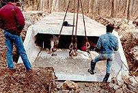
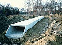
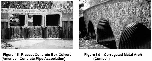
1 : Culvert Hydraulis Bob Pitt University of Alabama and Sirley Clark Penn State - Harrisburg Culvert Flow Culvert Systems Culverts typially used in roadway rossings and detention pond outlets. Headwater elevation water surfae elevation just upstream of te ulvert Tailwater elevation water surfae elevation just downstream of te ulvert Analysis typially for: Size, sape and number of new or additional ulverts needed to pass a design disarge Hydrauli apaity of existing ulvert system Upstream flood level at an existing ulvert system resulting from a speifi disarge rate Hydrauli performane urves for a ulvert system (wi are used to assess ydrauli risk at a rossing or as input for anoter ydrauli or ydrologi model
2


3 From: FHWA. Hydrauli esign of Higway Culverts. From: FHWA. Hydrauli esign of Higway Culverts. From: FHWA. Hydrauli esign of Higway Culverts. 3
4 Culvert Hydraulis: Control Type Culverts at as a signifiant onstrition to flow and are subjet to a range of flow types, inluding bot gradually varied and rapidly varied flow. Simplify by ontrol type: Outlet Control Assumption: Computes te upstream eadwater dept using onventional ydrauli metodologies tat onsider te predominant losses due to ulvert barrel frition Also inludes minor entrane and exit losses. Tailwater ondition as important effet on ulvert system. Inlet Control Assumption: Computes upstream eadwater dept resulting from onstrition at te ulvert entrane Neglets ulvert barrel frition, tailwater elevation and oter minor losses. Te ontrolling eadwater dept is te large of te omputed inlet and outlet ontrol eadwater depts (sine a single ulvert may at times operate under ea of te two ontrol types. Culvert Hydraulis: Outlet Control Headwater dept is found by summing te tailwater dept, entrane minor loss, exit minor loss and frition losses along te ulvert barrel. Energy basis for solving te outlet ontrol eadwater (HW) for a ulvert under inlet ontrol is given by te basi energy equation, rewritten for ulvert terms. V V HW 0 g g u d TW H Were HW 0 eadwater dept above outlet invert (lengt) V u approa veloity (lengt/time) TW tailwater dept above outlet invert (lengt) V d exit veloity (lengt/time) H sum of all losses (entrane minor loss [H E ] barrel frition losses (H F ) exit loss [H O ] oter losses), (lengt) Culvert Hydraulis: Outlet Control Culvert Hydraulis: Outlet Control Wen te ulverts onnet ponds or oter waterbodies wit negligible veloity on te upstream and downstream, te equation simplified to: HW 0 TW H Culverts are often ydraulially sort (meaning tat uniform dept will not be aieved during water s passage troug te ulvert). Solved using te gradually-varied flow analysis teniques. 4

5 Culvert Hydraulis: Outlet Control Entrane losses due to ontration of flow as it enters te ulvert. Entrane losses are a funtion of barrel veloity ead just inside te entrane, wit te smooter entranes aving te lowest entrane loss oeffiients. Entrane losses expressed using te following equation: H E k e V g Were H E entrane loss (lengt) k e entrane loss oeffiient V veloity just inside barrel entrane (lengt/time) g gravitational onstant (lengt/time ) From: FHWA. Hydrauli esign of Higway Culverts. From: FHWA. Hydrauli esign of Higway Culverts. From: FHWA. Hydrauli esign of Higway Culverts. 5
6 Culvert Hydraulis: Outlet Control Culvert Type Pipe, Conrete Entrane Type and esription Projeting from fill, soket end (groove-end) Entrane oss Coeffiient, k e 0.3 Projeting from fill, square ut end Headwall or eadwall wit wingwalls Soket end of pipe (groove-end) Square edge Rounded (radius / ) itered to onform to fill slope End-setion onfirming to fill slope Beveled edges, 33.7 o or 45 o levels 0. Side or slope-tapered inlet 0. Culvert Hydraulis: Outlet Control Culvert Type Box Culvert Entrane Type and esription Headwall parallel to embankment (no wingwalls) Square-edged on 3 edges Rounded on 3 edges (to radius of / barrel dimension or beveled edges on 3 sides) Wingwalls at 30 o to 75 o barrel Square-edged at rown Crown edge rounded (to radius of / barrel dimension, or beveled top edge) Wingwall at 0 o to 5 o to barrel Square-edged at rown Wingwalls parallel (extension of sides) Square-edged at rown Side or slope-tapered inlet Entrane oss Coeffiient, k e Culvert Hydraulis: Outlet Control Culvert Type Pipe or Pipe Ar, Corrugated etal Entrane Type and esription Projeting from fill (no eadwall) Headwall or eadwall and wingwalls square-edge itered to onform to fill slope, paved or unpaved edge End-setion onfirming to fill slope Entrane oss Coeffiient, k e Beveled edges, 33.7 o or 45 o levels 0. Side or slope-tapered inlet 0. Culvert Hydraulis: Outlet Control Exit loss is an expansion loss. Funtion of ange in veloity ead tat ours at te disarge end of te ulvert. Exit losses expressed using te following equation: d H O.0 V g Were H O exit loss (lengt) V d veloity of outfall annel V veloity just inside end of ulvert barrel (lengt/time) g gravitational onstant (lengt/time ) V g Wen disarge is negligible, exit loss equal to barrel veloity ead. Typially solved using gradually-varied flow analysis. 6
7 Culvert Hydraulis: Inlet Control Wen operating under inlet ontrol, ydrauli ontrol setion is ulvert entrane. Typially, te frition and minor losses in te ulvert are not as signifiant. Critial dept normally ours at or near te inlet, and flow downstream of te inlet are superritial. Tree types of inlet ontrol: For low disarge onditions, te ulvert entrane ats as a weir. Wen te ulvert is fully submerged, te inlet operates as an orifie. Transitional Region just above te unsubmerged zone and below te fully submerged zone. Culvert Hydraulis: Inlet Control Flow Two equations possible (typial to use te nd one for and als). : HW H Q A i 0. 5 S : HW Q 0. 5 A Were HW i eadwater dept above te ontrol setion invert (lengt) interior eigt of ulvert barrel (lengt) itered inlets: H speifi ead at ritial dept, y V /g (lengt/time) use slope Q ulvert disarge (lengt 3 /time) orretion fator A full ross-setional area of te ulvert barrel (lengt ) of 0.7S instead S ulvert barrel slope of -S, onstants from table Culvert Hydraulis: Inlet Control Culvert Hydraulis: Inlet Control Flow for submerged (orifie) flow: HW Q i 0. A 5 S itered inlets: use slope orretion fator of 0.7S instead of -S Were HW i eadwater dept above te ontrol setion invert (lengt) interior eigt of ulvert barrel (lengt) H speifi ead at ritial dept, y V /g (lengt/time) Q ulvert disarge (lengt 3 /time) A full ross-setional area of te ulvert barrel (lengt ) S ulvert barrel slope, onstants from table, onstants from table for submerged flow appliable wen Q/A i
8 Sape and aterial Cirular Conrete Cirular CP Cirular Sape and aterial Box Box, ¾ Camfers Coeffiients for Inlet Control esign Inlet Edge esription Square edge wit eadwall Groove end wit eadwall Groove end projeting Headwall itered to slope Projeting Beveled ring, 45 o bevels Beveled ring, 33.7 o bevels Coeffiients for Inlet Control esign Inlet Edge esription ¾ amfers, 45 o skewed eadwall ¾ amfers, 30 o skewed eadwall ¾ amfers, 5 o skewed eadwall 45 o bevels; 0 o -45 o skewed eadwall 45 o non-offset wingwall flares 8.4 o non-offset wingwall flares 8.4 o non-offset wingwall flares, 30 o skewed barrel Sape and aterial Box Box Box Sape and aterial Box, Top Bevels C Boxes Horizontal Ellipse Conrete Coeffiients for Inlet Control esign Inlet Edge esription 30 o to 75 o wingwall flares o and 5 o wingwall flares 0 o wingwall flares 45 o wingwall flares d o to 33.7o wingwall flare d o eadwall wit ¾ amfers 90 o eadwall wit 45 o bevels 90 o eadwall wit 33.7 o bevels Coeffiients for Inlet Control esign Inlet Edge esription 45 o wingwall flares offset 33.7 o wingwall flares offset 8.4 o wingwall flares offset 90 o eadwall Tik wall projeting Tin wall projeting Square edge wit eadwall Groove end wit eadwall Groove end projeting
9 Sape and aterial Vertial Ellipse Conrete Pipe Ar 8 Corner Radius C Pipe Ar 8 Corner Radius C Sape and aterial Elliptial Inlet Fae Conrete Conrete Coeffiients for Inlet Control esign Inlet Edge esription Square edge wit eadwall Groove end wit eadwall Groove end projeting o eadwall itered to slope Projeting Projeting No bevels o bevels Coeffiients for Inlet Control esign Inlet Edge esription Tapered inlet - beveled edges Tapered inlet - square edges Tapered inlet tin edge projeting Tapered inlet troat Side tapered less favorable design Side tapered more favorable design Slope tapered less favorable design Slope tapered more favorable design Coeffiients for Inlet Control esign Sape and aterial Pipe Ar 3 Corner Radius C Inlet Edge esription Projeting No bevels 33.7 o bevels Ar C 90o eadwall itered to slope Tin wall projeting Cirular Smoot tapered inlet troat Roug tapered inlet troat Hydrauli Operation of Culverts: Simplified Hydraulis of ulverts an be lassified into four ategories:. inlet and outlet. inlet wit full flow but free disarge at te outlet 3. inlet wit partially full pipe flow 4. inlet 9
10 Hydrauli Operation of Culverts: Simplified Culvert Operation: Inlet and Outlet for eadloss in tis ulvert type in a irular ulvert: gn 8Q k e 4/3 4 R π g Were Q disarge diameter R ydrauli radius of te ulvert barrel ( /4 for full-flowing barrel) Culvert Operation: Inlet and Outlet Culvert disarge is primarily affeted by tailwater elevation (TW) and te ead loss of te ulvert (regardless of ulvert slope). Culvert flow an be treated as pressure pipe flow. Headloss is sum of ulvert ead loss and exit and entrane losses. for eadloss in tis ulvert: k e V g n R V Entrane oeffiient, k e, approximately for a squareedged entrane and 0. for a well-rounded entrane. anning s n: n 0.03 for onrete; n 0.04 for orrugated metal pipe. 4/3 V g Culvert Operation: Inlet wit Free Outlet isarge If te disarge arried in a ulvert as a normal dept larger tan te barrel eigt, te ulvert will flow full even if te tail water level drops below tat of te outlet. isarge is ontrolled by eadloss and level of eadwater. are same as for te submerged inlet and outlet. 0
11 Culvert Operation: Inlet wit Partially Full Pipe Flow If te normal dept is less tan te barrel eigt, wit te inlet submerged and free disarge at te outlet, a partially full pipe flow ondition will normally result. Te ulvert disarge is ontrolled by te entrane onditions (ead water, barrel area, and edge onditions), and te flow is under entrane ontrol. isarge alulated by te orifie equation: Q C d A g Were ydrostati ead above te enter of te pipe opening A ross-setional area C d oeffiient of disarge (C d 0.6 for squareedged entrane and C d.0 for well-rounded entrane) Culvert Hydraulis: Example A orrugated steel pipe is used as a ulvert tat must arry a flow rate of 5.3 m 3 /se and disarge into te air. At te entrane, te maximum available ead water is 3. m above te ulvert invert. Te ulvert is 35 m long and as a square-edged entrane and slope of etermine te diameter of te pipe. Culvert Operation: Inlet Wen te ydrostati ead at te entrane is less tan., air will break into te barrel. No longer pressure pipe flow. Culvert slope and barrel wall frition will ditate flow. ue to a sudden redution of water area at entrane, flow usually enters te ulvert in superritial ondition. Critial dept takes plae at te entrane of te barrel. If frition is suffiient, dept of flowing water inreases. epending on tailwater elevation, superritial flow may onvert to subritial flow troug ydrauli jump. Water surfae profile alulated using gradually-varied flow equations. Culvert Hydraulis: Example Of te four types of ulvert ydraulis, determine te type. Not unsubmerged inlet. Not submerged outlet. Cek for submerged inlet wit partially full flow and pressurized pipe flow. Assume full pipe flow: H 3. k e gn R g S o 4/3 (0.003)(35 (0.04) ( / 4) π 4/3 8 m (35 ) Q g m ) (5.3 π m 3 / g se) 4
12 Culvert Hydraulis: Example Assume full pipe flow: m.4 m g (0.04) ( / 4).5.5 4/3.3 4 (35m ) 4/3 8(5.3 m π 3 /se) 4 g Culvert Hydraulis: Example Assume partially full pipe flow: isarge ontrolled by entrane ondition only. Orifie ula (and substituting for ): Q C d 5.3 m 3 / A.4 se m g (0.6) π 4 g 3. Resistane to flow in te pipe limits te flow. Terefore, use te diameter alulated wit tis assumption (submerged inlet and full pipe flow)..4 m Culvert Hydraulis: Example Assume partially full pipe flow: isarge ontrolled by entrane ondition only. Head is measured above enterline of pipe m Summary of Culvert Flow Conditions: Prasun 987
The Basics of Culvert and Inlet Design
 PDHonline Course C619 (8 PDH) The Basics of Culvert and Inlet Design Jerry D. Morrow, PE 2013 PDH Online PDH Center 5272 Meadow Estates Drive Fairfax, VA 22030 6658 Phone & Fax: 703 988 0088 www.pdhonline.org
General Information for Culvert Design
 Design Manual Chapter 2 - Stormwater 2E - Culvert Design 2E-1 General Information for Culvert Design A. Introduction A culvert is a conduit under an embankment that transports stormwater from one side
CHAPTER 4 SPALDING COUNTY, GEORGIA 4.0 CULVERT DESIGN
 SPALDING COUNTY, GEORGIA CHAPTER 4 4.0 CULVERT DESIGN... 4-1 4.1 INTRODUCTION... 4-1 4.2 SYMBOLS AND DEFINITIONS... 4-1 4.3 ENGINEERING DESIGN CRITERIA... 4-2 4.3.1 FREQUENCY FLOOD... 4-2 4.3.2 VELOCITY
CHAPTER 5 CULVERT DESIGN
 CHAPTER 5 CULVERT DESIGN HYDRAULICS OF CULVERTS There are two major types of culvert flow: 1) flow with inlet control, and 2) flow with outlet control. For each type, different factors and formulas are
Chapter 2 FLUID STATICS by Amat Sairin Demun
 Capter FLUID STTICS by mat Sairin Demun Learning Outomes Upon ompleting tis apter, te students are expeted to be able to: 1. Calulate te pressure in pipes by using piezometers and manometers.. Calulate
APPENDIX B HYDRAULIC DESIGN DATA FOR CULVERTS
 TM 5-820-4/AFM 88-5, Chap 4 APPENDIX B HYDRAULIC DESIGN DATA FOR CULVERTS B-1. General. a. This appendix presents diagrams, charts, coefficients and related information useful in design of culverts. The
HURRICANE SANDY LIMITED REEVALUATION REPORT UNION BEACH, NEW JERSEY DRAFT ENGINEERING APPENDIX SUB APPENDIX E OVERTOPPING & FAILURE ANALYSIS
 HURRICANE SANDY LIMITED REEVALUATION REPORT UNION BEACH, NEW JERSEY DRAFT ENGINEERING APPENDIX SUB APPENDIX E OVERTOPPING & FAILURE ANALYSIS Revised 18 Feb 2015 1 OVERTOPPING & FAILURE ANALYSIS 1.0 Introdution
Indiana LTAP Road Scholar Core Course #10 Culvert Drainage. Presented by Thomas T. Burke, Jr., PhD, PE Christopher B. Burke Engineering, Ltd.
 Indiana LTAP Road Scholar Core Course #10 Culvert Drainage Presented by Thomas T. Burke, Jr., PhD, PE Christopher B. Burke Engineering, Ltd. Objectives Review culvert shapes, end sections, and materials
Culvert Design Basics
 PDHonline Course C287 (4 PDH) Culvert Design Basics Instructor: George E. Thomas, PE 2012 PDH Online PDH Center 5272 Meadow Estates Drive Fairfax, VA 22030-6658 Phone & Fax: 703-988-0088 www.pdhonline.org
HY-8 Version 7.2 Build Date January 17, Federal Highway Administration.
 HY-8 Version 7.2 Build Date January 17, 2012 Federal Highway Administration http://www.fhwa.dot.gov/engineering/hydraulics/software/hy8/index.cfm SIMPLE Simple to use Use for simple culverts and bridges
Culvert Design An Overview of the NYS Highway Design Manual Chapter 8
 Seventeenth Statewide Conference on Local Bridges Culvert Design An Overview of the NYS Highway Design Manual Chapter 8 Tuesday, October 25, 2011 Training Session: Culvert Design, Analysis - talk 2 Presented
WMS 8.4 Tutorial Hydraulics and Floodplain Modeling HY-8 Modeling Wizard Learn how to model a culvert using HY-8 and WMS
 v. 8.4 WMS 8.4 Tutorial Hydraulics and Floodplain Modeling HY-8 Modeling Wizard Learn how to model a culvert using HY-8 and WMS Objectives Define a conceptual schematic of the roadway, invert, and downstream
Culvert Hydraulics: Comparison of Current Computer Models
 Brigham Young University BYU ScholarsArchive All Theses and Dissertations 2007-03-13 Culvert Hydraulics: Comparison of Current Computer Models Elizabeth Anne Thiele Brigham Young University - Provo Follow
General Technical Data and Calculations
 18 Bosh Rexroth AG R31EN 232 (26.4) General Produt Desription General Tehnial Data and Calulations Fores and load moments In Rexroth the running traks are arranged at a ompression angle of 45. This results
APPENDICES STRANDJACK WEDGES Friction coefficients, micro slip and handling
 APPENDICES STRANDJACK WEDGES Frition oeffiients, miro slip and handling Report nr. DCT 2005-78 By: H.G.M.R. van Hoof Idnr : 501326 20 November, 2005 Researh strand jak wedges Appendies By H.G.M.R. van
Chapter 5. Specific Energy. The total energy of a channel flow referred to datum is given by,
 Chapter 5 Speifi ner 5.. Introdution The total ener of a hannel flow referred to datum is iven b, H z (5.) If the datum oinides with the hannel bed at the ross-setion, the resultin expression is know as
Section 5: Pond Outlets
 Section : Pond Outlets Defining and calculating pond outlet devices 8 Minutes Press Space, PageDown, or Click to advance. Press PageUp to reverse. Esc to exit. Right-Click for other options. Outlets Introduction
The following excerpt are pages from the North American Product Technical Guide, Volume 2: Anchor Fastening, Edition 17.
 The following exerpt are pages from the North Amerian Produt Tehnial Guide, Volume 2: Anhor Fastening, Edition 17. Please refer to the publiation in its entirety for omplete details on this produt inluding
Exercise (4): Open Channel Flow - Gradually Varied Flow
: Open Channel Flow - Gradually Varied Flow") Exercise (4): Open Channel Flow - Gradually Varied Flow 1) A wide channel consists of three long reaches and has two gates located midway of the first and last reaches. The bed slopes for the three reaches
Exercise (4): Open Channel Flow - Gradually Varied Flow 1) A wide channel consists of three long reaches and has two gates located midway of the first and last reaches. The bed slopes for the three reaches
Physics 20 Lesson 20 Uniform Circular Motion Vertical Plane
 Physis 0 Lesson 0 Uniform Cirular Motion Vertial Plane I. Vertial uniform irular motion Refer to Pearson pages 60 to 64 for a disussion about irular motion. So far we hae onsidered uniform irular motion
Sight Distance. The availability of sufficient sight distance for the driver to see ahead is critical to the design of a safe highway.
 Sigt Distance Te availability of sufficient sigt distance for te driver to see aead is critical to te design of a safe igway. Wat is sigt distance? Sigt distance is te lengt of igway visible to a driver.
BERMAD Irrigation. IR-100 hyflow Basic Valve. Basic Valve.
 Basic Valve IR- Yflow Basic Valve Te BERMAD basic Model IR- Yflow diapragm actuated, ydraulically operated valve is at te leading edge of control valve design. It combines simple and reliable construction
APPENDIX A STRUCTURE DESCRIPTIONS AND RATING CURVES
 3 4 5 6 7 8 9 0 3 APPENDIX A STRUCTURE DESCRIPTIONS AND RATING CURVES Kissimmee River Vol December 005 Version Draft 4 3 4 5 6 7 8 9 0 3 4 5 6 7 8 9 0 3 4 5 6 7 8 9 30 3 3 33 34 35 36 37 38 39 40 4 4 43
5.8. Solving Three-Dimensional Problems by Using Trigonometry. LEARN ABOUT the Math. Matt s Solution. 328 Chapter 5
 YOU WILL NEE dynamic geometry software (optional) Solving Tree-imensional Problems by Using Trigonometry GOL Solve tree-dimensional problems by using trigonometry. LERN OUT te Mat From point, Manny uses
Chapter 11. Culverts and Bridges Design Checklist for Culvert Design
 Yes No N/A Design Requirements I. GENERAL DESIGN GUIDELINES Chapter 11. Culverts and Bridges A. Culvert design is in accordance with the Culverts chapter of Volume 2 of the UDFCD Manual for additional
Contents. LWN edition:
 Contents 7. Introdution... 7.- 7.. General Sizing Proedure... 7.- 7.. Seletion of the Sizing Standard... 7.-3 7. Engineering Support... 7.- 7.. List of Symbols... 7.- 7.. Properties of Gases... 7.- 7..3
BC Ministry of Forests. March Fish Stream Crossing Guidebook. Forest Practices Code of British Columbia.
 FRST 557 Lecture 7c Bridges and Culverts: Water Velocity and Discharge Lesson Background and Overview: The previous two lessons presented methods for estimating water volume flow at a particular site and
Culvert Design for Low and High Gradient Streams in the Midwest. Dale Higgins, Hydrologist Chequamegon-Nicolet National Forest
 Culvert Design for Low and High Gradient Streams in the Midwest Dale Higgins, Hydrologist Chequamegon-Nicolet National Forest Overview Culvert Design Considerations Hydraulic Terms Culvert Impacts Low
The following excerpt are pages from the North American Product Technical Guide, Volume 2: Anchor Fastening, Edition 16.
 The following exerpt are pages from the North Amerian Produt Tehnial Guide, Volume 2: Anhor Fastening, Edition 16. Please refer to the publiation in its entirety for omplete details on this produt inluding
The following excerpt are pages from the North American Product Technical Guide, Volume 2: Anchor Fastening, Edition 16.1.
 The following exerpt are pages from the North Amerian Produt Tehnial Guide, Volume 2: Anhor Fastening, Edition 16.1. Please refer to the publiation in its entirety for omplete details on this produt inluding
IKGAtl Kenneth Grubb Associates Ltd
 IKGAtl Kenneth Grubb Assoiates Ltd BURO HAPPOLD COPPERHOUSE SLUICE GATE DOCUMENT REVISION RECORD Doument Number: Number of Pages: Doument Title: Saved as: C0395/006/DOC 31 REPORT ON THE MECHANICAL SURVEY
Driveway Design Criteria
 Design Manual Chapter 5 - Roadway Design 5L - Access Management 5L-4 Driveway Design Criteria A. General For efficient and safe operations, access drives and minor public street intersections can be improved
ME 425: Aerodynamics
 ME 45: Aeroynamis Dr. A.B.M. Toufique Hasan Professor Department of Mehanial Engineering Banglaesh University of Engineering & Tehnology BUET, Dhaka Leture-6 /5/8 teaher.buet.a.b/toufiquehasan/ toufiquehasan@me.buet.a.b
D emonstration of Possible F low Conditions in a Culvert
 D emonstration of Possible F low Conditions in a Culvert M. R. CARSTENS, Associate Professor, Georgia Institute of Technology and A. R. HOLT, Lt. U.S. Army Corps of Engineers, Fort Belvoir, Virginia e
Areas of Trapezoids, Rhombuses, and Kites. To find the area of a trapezoid, rhombus, or kite
 10-2 Areas of Trapezoids, Rombuses, and Kites Common Core State Standards G-MG.A.1 Use geometric sapes, teir measures, and teir properties to describe objects. MP 1, MP 3, MP 4, MP 6 Objective To find
Young s modulus measurement of wood and CFRP
 Deiverae WP D.4 First Detaied Design and Laoratory Testing 7-1 Young s moduus measurement of wood and CFRP Viet An Nguyen, Roert Le Roy, Jean-François Caron 1. Ojetives Te ojetive is to arry out ending
Storm Damage Floating Culverts & Other Inlet Issues
 Storm Damage Floating Culverts & Other Inlet Issues Mark Bailey, PE - Hydraulic Manager, INDOT Dale Sedler, PE - Sr. Hydraulic Engineer, INDOT Road School 2016 What causes a culvert to float? 1. Accumulation
APPENDIX J HYDROLOGY AND WATER QUALITY
 APPENDIX J HYDROLOGY AND WATER QUALITY J-1 Technical Report on Airport Drainage, Northern Sector Airport and Ordinance Creek Watershed / Preliminary Creek Constructed Natural Channel Culvert J-2 Preliminary
Technical Report Culvert A Hydraulic Analysis
 DATE: November 3, 2011 Technical Report Culvert A Hydraulic Analysis TO: FROM: RE: Jim Reiser, P.E. Project Manager Parsons Brinckerhoff, Inc. Kurt Killian, P.E., CFM Parsons Brinckerhoff, Inc. Design
UNDERWATER INSPECTION REPORT DOUBLE CORRUGATED METAL PIPE CULVERT HAWTHORN ROAD OVER RICE CREEK (PELKEY LAKE) MORRISON COUNTY
 MORRISON COUNTY") UNDERWATER INSPECTION REPORT DOUBLE CORRUGATED METAL PIPE CULVERT HAWTHORN ROAD OVER RICE CREEK (PELKEY LAKE) MORRISON COUNTY OCTOBER 25, 2012 PREPARED FOR MORRISON COUNTY PUBLIC WORKS BY COLLINS ENGINEERS,
UNDERWATER INSPECTION REPORT DOUBLE CORRUGATED METAL PIPE CULVERT HAWTHORN ROAD OVER RICE CREEK (PELKEY LAKE) MORRISON COUNTY OCTOBER 25, 2012 PREPARED FOR MORRISON COUNTY PUBLIC WORKS BY COLLINS ENGINEERS,
Fish Passage Planning and Design
 Fish Passage Planning and Design Culvert Fishway Planning and Design Guidelines Part I Design Drawings for Fishway Projects Ross Kapitzke James Cook University School of Engineering and Physical Sciences
SELBY CREEK SILVERADO TRAIL CULVERT FISH PASSAGE ASSESSMENT
 SELBY CREEK SILVERADO TRAIL CULVERT FISH PASSAGE ASSESSMENT NAPA COUNTY, CALIFORNIA PREPARED BY NAPA COUNTY RESOURCE CONSERVATION DISTRICT 1303 JEFFERSON ST. SUITE 500B NAPA, CALIFORNIA 94559 WWW.NAPARCD.ORG
Sediment Basin 7E-12. Design Manual Chapter 7 - Erosion and Sediment Control 7E - Design Information for ESC Measures BENEFITS.
 7E-12 Design Manual Chapter 7 - Erosion and Sediment Control 7E - Design Information for ESC Measures Sediment Basin BENEFITS Flow Control Erosion Control Sediment Control Runoff Reduction Flow Diversion
Modelling the decrease in wave height over the shoreface due to slope-induced changes in bottom friction.
 Chapter : Modelling the derease in wave height over the shorefae due to slope-indued hanges in bottom frition. Abstrat Wave height-redution on the shorefae is partly indued by frition at the bottom. The
Outlet Structures T-12
 Description This section provides guidance and details for outlet structures for use primarily with BMPs utilizing sedimentation, (i.e., extended detention basins (EDBs), retention ponds, and constructed
STRUCTURE 65-B PURPOSE SPILLWAY OPERATION
 STRUCTURE 65-B This structure is a reinforced concrete, gated spillway with discharge controlled by three cable operated vertical lift gates and a reinforced concrete lock structure with two pairs of sector
WIND TUNNEL MEASUREMENT AND ASSESSMENT ON THE PEDESTRIAN WIND ENVIRONMENT A CASE STUDY OF JINYING HIGH RISE BUILDING IN TAIPEI, TAIWAN
 WIND TNNEL MEASREMENT AND ASSESSMENT ON THE PEDESTRIAN WIND ENVIRONMENT A CASE STDY OF JINYING HIGH RISE BILDING IN TAIPEI, TAIWAN Bao-Shi Shiau 1 and Ben-Jue Tsai 2 ABSTRACT In this paper, wind tunnel
Full scale measurements of pressure equalization on air permeable façade elements
 Full sale measurements of pressure equalization on air permeable façade elements Carine van Bentum, Chris Geurts Department of Strutural Dynamis, TNO, Delft, The Netherlands email: arine.vanbentum@tno.nl,
TABLE OF CONTENTS...2 APPENDIX A ANCHORHEADS...3 APPENDIX B WEDGE PROPERTIES...5 APPENDIX C
 Table of ontents TABLE OF CONTENTS...2 APPENDIX A ANCHORHEADS...3 APPENDIX B WEDGE PROPERTIES...5 APPENDIX C 18 MM DYFORM STRANDS...6 APPENDIX D OPERATION CYCLES STRANDJACK UNIT...7 D.1 JACK UP CYCLE (LIFTING
Water )الطرق المائي( Hammer -3 rd Class Dr. Sataa A. F. Al-Bayati (08-09)
الطرق المائي( Hammer -3 rd Class Dr. Sataa A. F. Al-Bayati (08-09)") بسم هللا الرحمن الرحيم Water )الطرق المائي( Hammer -3 rd Class Dr. Sataa A. F. Al-Bayati (08-09) Water hammer is the momentary inrease in ressure, whih ours in a water system when there is a sudden hange
بسم هللا الرحمن الرحيم Water )الطرق المائي( Hammer -3 rd Class Dr. Sataa A. F. Al-Bayati (08-09) Water hammer is the momentary inrease in ressure, whih ours in a water system when there is a sudden hange
Experimental Study on the Limits of Flow Regimes for Different Configurations of Stepped Spillway
 Civil and Environmental Researh Experimental Study on the Limits of Flow Regimes for Different Configurations of Stepped Spillway Najm Obaid Salim Alghazali 1*, Salam M. Jasim 2 1. Asst. Prof. Dotor, Civil
CITY OF ROSEVILLE DESIGN STANDARDS
 CITY OF ROSEVILLE DESIGN STANDARDS Section 1 Purpose and Definitions 1-1 Purpose PD 1 1-2 Design Practice PD 1 1-3 Definitions PD 1 Section 2 General Requirements 2-1 Plans by an Appropriate Engineer GR
Advanced Hydraulics Prof. Dr. Suresh A. Kartha Department of Civil Engineering Indian Institute of Technology, Guwahati
 Advanced Hydraulics Prof. Dr. Suresh A. Kartha Department of Civil Engineering Indian Institute of Technology, Guwahati Module - 4 Hydraulic Jumps Lecture - 1 Rapidly Varied Flow- Introduction Welcome
Analysis of a Twin Screw Expander for ORC Systems using Computational Fluid Dynamics with a Real Gas Model
 Purdue University Purdue e-pubs International Compressor Engineering Conferene Shool of Mehanial Engineering 2014 Analysis of a Twin Srew Expander for ORC Systems using Computational Fluid Dynamis with
BKTA: 3-way change-over ball valve (T) with male thread, PN 40
 with male thread, PN 40") BKTA: 3-way hange-over ball valve (T) with male thread, PN 40 ow energy effiieny is improved Effiieny means preise hangeover with minimum leakage Features 3-way hange-over ball valve with T-bore for use
BKTA: 3-way hange-over ball valve (T) with male thread, PN 40 ow energy effiieny is improved Effiieny means preise hangeover with minimum leakage Features 3-way hange-over ball valve with T-bore for use
Homework of Chapter (4.2,4.3)
") Dead Line: Saturday (24/3/2018) The Islamic University of Gaza, Instructors: Dr. Khalil M. Al Astal Civil Engineering Department, Hydraulics -Discussion, Second semester, 2018. T.A: Eng. Mohammed AbuRahma
Dead Line: Saturday (24/3/2018) The Islamic University of Gaza, Instructors: Dr. Khalil M. Al Astal Civil Engineering Department, Hydraulics -Discussion, Second semester, 2018. T.A: Eng. Mohammed AbuRahma
Experiment 8: Minor Losses
 Experiment 8: Minor Losses Purpose: To determine the loss factors for flow through a range of pipe fittings including bends, a contraction, an enlargement and a gate-valve. Introduction: Energy losses
Sample Problems. Lecture Notes Motion Problems page 1
 Lecture Notes Motion Problems page 1 Sample Problems 1. We traveled for nine ours. Ten we increased our velocity by 10 les per our and traveled an additional ve ours. Wat was our original velocity if all
EFFECTIVE STRESS CONCEPT NO SEEPAGE
 4.330 SOIL MENIS EFFETIVE STRESS ONEPT NO SEEPGE Total Stress ( at Point ( sat Satrated Soil olmn (Figre 6.. Das FGE (005 from Water from Soil Were: = Unit Weigt of Water sat = Satrated Unit Weigt of Soil
Investigation on the Vortex Thermal Separation in a Vortex Tube Refrigerator
 doi: 1.236/sieneasia13-1874.2.31.2 SieneAsia 31 (2): 2-223 Investigation on the Vortex Thermal Separation in a Vortex Tube Refrigerator Pongjet Promvonge* and Smith Eiamsa-ard Department of Mehanial Engineering,
PENNDRAIN.rep. HEC-RAS Version May 2005 U.S. Army Corp of Engineers Hydrologic Engineering Center 609 Second Street Davis, California
 HEC-RAS Version 3.1.3 May 2005 U.S. Army Corp of Engineers Hydrologic Engineering Center 609 Second Street Davis, California X X XXXXXX XXXX XXXX XX XXXX X X X X X X X X X X X X X X X X X X X XXXXXXX XXXX
Appendix G. Alternative Solutions Details. Krosno Creek Flood Reduction Project PROJECT FILE REPORT CITY OF PICKERING
 Krosno Creek Flood Reduction Project PROJECT FILE REPORT CITY OF PICKERING Appendix G Alternative Solutions Details TMIG THE MUNICIPAL INFRASTRUCTURE GROUP LTD Krosno Creek Flood Reduction Project PROJECT
ME 425: AERODYNAMICS
 ME 45: AERODYNAMICS - Dr. A.B.M. Toufique Hasan Professor Department of Mehanial Engineering, BUET Leture # 3 4 Otober, 6 http://teaher.buet.a.bd/toufiquehasan/ourses.php ME45: Aerodynamis Airfoil Nomenlature
Dynamic Modeling of the Water Balance in the Cathode Gas Diffusion Layer of Polymer Electrolyte Fuel Cells
 Dynami Modeling of the Water Balane in the Cathode Gas Diffusion Layer of Polymer Eletrolyte Fuel Cells D. Fofana, K. Agbossou, Y. Dubé, J. Hamelin This doument appeared in Detlef Stolten, Thomas Grube
UNDERWATER BRIDGE INSPECTION REPORT STRUCTURE NO CSAH 133 OVER A DITCH ST. LOUIS COUNTY
 UNDERWATER BRIDGE INSPECTION REPORT STRUCTURE NO. 7780 CSAH 133 OVER A DITCH ST. LOUIS COUNTY SEPTEMBER 27, 2012 PREPARED FOR THE MINNESOTA DEPARTMENT OF TRANSPORTATION BY COLLINS ENGINEERS, INC. JOB NO.
Measurement System of Bubbly Flow Using Ultrasonic Velocity Profile Monitor and Video Data Processing Unit, (II)
") Journal of Nulear Siene and Tehnology SSN: 22-3131 (Print) 1881-1248 (Online) Journal homepage: http://www.tandfonline.om/loi/tnst2 Measurement System of Bubbly Flow Using Ultrasoni Veloity Profile Monitor
Journal of Nulear Siene and Tehnology SSN: 22-3131 (Print) 1881-1248 (Online) Journal homepage: http://www.tandfonline.om/loi/tnst2 Measurement System of Bubbly Flow Using Ultrasoni Veloity Profile Monitor
OFFICE OF STRUCTURES MANUAL FOR HYDROLOGIC AND HYDRAULIC DESIGN CHAPTER 13 CULVERTS APRIL 2011
 OFFICE OF STRUCTURES MANUAL FOR HYDROLOGIC AND HYDRAULIC DESIGN CHAPTER 13 CULVERTS APRIL 2011 APRIL 2011 Chapter 13 Culverts Table of Contents Foreword.3 13.1 Introduction.. 4 13.2 Policy 6 13.3 Passage
Effect of Pavement/Shoulder Drop-Offs on Highway Safety
 Effet of Pavement/Shoulder Drop-Offs on Highway Safety John C. Glennon Transportation Consulting Engineer Overland Park, Kansas Drop-offs at the pavement/shoulder (or shoulder/roadside) edge have been
Fish Passage Assessment Report Mare Brook Culverts
 Fish Passage Assessment Report Mare Brook Culverts Fish Passage Assessment Component of Mare Brook Watershed Assessment and Community Engagement Project Prepared for: FB Environmental Associates 97A Exchange
CONTROLLED MARINE AREA (SEISMIC SURVEY WORKS) REGULATIONS 2016
 REGULATIONS 2016") Controlled Marine Area (Seismi Survey Works) Regulations 2016 Statutory Doument No. 2016/0362 Marine Infrastruture Management At 2016 CONTROLLED MARINE AREA (SEISMIC SURVEY WORKS) REGULATIONS 2016 Laid
Controlled Marine Area (Seismi Survey Works) Regulations 2016 Statutory Doument No. 2016/0362 Marine Infrastruture Management At 2016 CONTROLLED MARINE AREA (SEISMIC SURVEY WORKS) REGULATIONS 2016 Laid
Evaluating Surge Potential in CSO Tunnels
 14 Evaluating Surge Potential in CSO Tunnels Karen E. Ridgway Tunnels are being proposed to control combined sewer overflow (CSO) in numerous cities in the United States and Canada. The tunnels are intended
APPENDIX A STRUCTURE DESCRIPTIONS AND RATING CURVES. Lake Okeechobee & EAA Vol 3 A-i December 2005 Version 1 Draft 4
 1 1 1 1 1 1 1 1 0 1 0 1 0 APPENDIX A STRUCTURE DESCRIPTIONS AND RATING CURVES Lake Okeechobee & EAA Vol A-i December 00 1 1 1 1 1 1 1 1 0 1 from the drainage area served, under a design head of. feet pool
Advanced Hydraulics Prof. Dr. Suresh A. Kartha Department of Civil Engineering Indian Institute of Technology, Guwahati
 Advanced Hydraulics Prof. Dr. Suresh A. Kartha Department of Civil Engineering Indian Institute of Technology, Guwahati Module - 4 Hydraulics Jumps Lecture - 4 Features of Hydraulic Jumps (Refer Slide
EurOtop revisited. Part 2: Vertical Structures
 EurOtop revisited. Part 2: Vertial Strutures Tom Brue University of Edinburg, Edinburg, Sotland Jentsje van der Meer Van der Meer Consulting BV, Akkrum, Te Neterlands William Allsop Wallingford, Wallingford,
MEMO. Schedule 'B' Class Environmental Assessment and Preliminary Design Lakeview Boulevard Improvements Culvert Assessment.
 MEMO Schedule 'B' Class Environmental Assessment and Preliminary Design Lakeview Boulevard Improvements Culvert Assessment February 15, 2017 As per the preferred Lakeview Boulevard alignment provided by
Design Overview. Section 4 Standard Plans for Design. Pedestrian Access Routes. Pedestrian Access Routes. Overview. Cross Slope
 Design Overview Section 4 Standard Plans for Design Fall, 2017 Ann Johnson, PE Services Brady Rutman, SRF Consulting Group Overview Design Basics Recommendations: The Zone System Driveway Crossings Pedestrian
Access requests to County streets and roadways are processed through one of the following methods:
 13.1 GENERAL APPLICATION PROCESS Access requests to County streets and roadways are processed through one of the following methods: A. Planned Developments may set general locations for access points.
Water surface slope extending up to 20 channel widths up and downstream of crossing.
 Site Evaluations Site Information Site Location: Mt ood NF, Forest Road 7 Year Installed: Pre-987 Lat/Long: 8 W Watershed rea (mi ): N Stream Slope (ft/ft) : Channel Type: Step-pool ankfull Width (ft):
TM /AFM 88-5, Chap Underground hydraulic design Inlets UFC - Drainage In Areas Other Than Airfields
 sults of laboratory research concerning soil infiltration through pipe joints and the effectiveness of gasketing tapes for waterproofing joints and seams are available. 3 6. Underground hydraulic design.
Great Lakes Stream Crossing Inventory Instructions
 Great Lakes Stream Crossing Inventory Instructions This document is a guide to completing the Stream Crossing Data Sheet (2/28/11 version). Careful attention to this guidance will ensure consistent crossing
MEMORANDUM. TNC Fisher Slough Final Design and Permitting Subject: DRAFT Technical Memorandum: Levee Emergency Spillway Design
 MEMORANUM TNC Fisher Slough Final esign and Permitting Subject: RAFT Technical Memorandum: Levee Emergency Spillway esign To: From: Internal Memorandum For Record Yen Hsu Chen (Tetra Tech) avid Cline (Tetra
CEE 345, Part 2, Winter 2012, Final Exam Solutions (Open Channel Flow)
") CEE 45, Part, Winter 0, Final Exam Solutions (Open Channel Flow). (a) (8) List and briefl describe the forces that must be considered in an analsis of flow in a trapezoidal channel with a slope of 0.006.
CEE 45, Part, Winter 0, Final Exam Solutions (Open Channel Flow). (a) (8) List and briefl describe the forces that must be considered in an analsis of flow in a trapezoidal channel with a slope of 0.006.
Lecture 10 : Sewer Appurtenances
 1 P age Module 8 : Sewer Appurtenances Lecture 10 : Sewer Appurtenances 2 P age The structures, which are constructed at suitable intervals along the sewerage system to help its efficient operation and
Operating Instructions Single/Dual Bourdon Tube Pressure Switches Type BS/BT/BX
 pproval data for Ex i swithes (BT and BX) pproval: II 1 G D Ex ia IIC T6 Ex ia D 20 T0 Operating Instrutions Single/Dual Bourdon Tube Pressure Swithes Type BS/BT/BX Certifiate no.: ISSeP08TEX016X Permissible
Khosla's theory. After studying a lot of dam failure constructed based on Bligh s theory, Khosla came out with the following;
 Khosla's theory After studying a lot of dam failure constructed based on Bligh s theory, Khosla came out with the following; Following are some of the main points from Khosla's Theory From observation
Plan B Dam Breach Assessment
 Plan B Dam Breach Assessment Introduction In support of the Local Sponsor permit applications to the states of Minnesota and North Dakota, a dam breach analysis for the Plan B alignment of the Fargo-Moorhead
3. GRADUALLY-VARIED FLOW (GVF) AUTUMN 2018
 AUTUMN 2018") 3. GRADUALLY-VARIED FLOW (GVF) AUTUMN 2018 3.1 Normal Flow vs Gradually-Varied Flow V 2 /2g EGL (energy grade line) Friction slope S f h Geometric slope S 0 In flow the downslope component of weight balances
3. GRADUALLY-VARIED FLOW (GVF) AUTUMN 2018 3.1 Normal Flow vs Gradually-Varied Flow V 2 /2g EGL (energy grade line) Friction slope S f h Geometric slope S 0 In flow the downslope component of weight balances
Apply the Law of Sines. You solved right triangles. You will solve triangles that have no right angle.
 13.5 pply te Lw of Sines TEKS.1,.4, 2.4.; P.3.E efore Now You solved rigt tringles. You will solve tringles tt ve no rigt ngle. Wy? So you n find te distne etween frwy ojets, s in Ex. 44. Key Voulry lw
DESIGN OF BELL-MOUTH SPILLWAY AT BARVI DAM
 DESIGN OF BELL-MOUTH SPILLWAY AT BARVI DAM Akshay Haldankar 1, Mahesh Bhadra 2, Rahul Harad 3, Darpan Kapre 4, Dipali Patil 5 1,2,3,4 Under graduate,dept. of Civil Engineering, DRIEMS Neral. 5Assistant
Culvert Inlet Failures-A Case History
 Culvert nlet Failures-A Case History ROY C. EDGERTON, Research Engineer, Oregon State Highway Department Bent-up ends have been experienced on three large structural plate culverts installed with the upstream
EXAMPLES (OPEN-CHANNEL FLOW) AUTUMN 2018
 AUTUMN 2018") EXAMPLES (OPEN-CHANNEL FLOW) AUTUMN 2018 Normal and Critical Depths Q1. If the discharge in a channel of width 5 m is 20 m 3 s 1 and Manning s n is 0.02 m 1/3 s, find: (a) the normal depth and Froude number
EXAMPLES (OPEN-CHANNEL FLOW) AUTUMN 2018 Normal and Critical Depths Q1. If the discharge in a channel of width 5 m is 20 m 3 s 1 and Manning s n is 0.02 m 1/3 s, find: (a) the normal depth and Froude number
ADA Training Standard Plans
 ADA Training Standard Plans SCREEN READABLE VERSION IS IN THE MAKING AND WILL BE MADE AVAILABLE SOON 2018 MnDOT 2 Standard Plans 2017 Overview Overview PROWAG and Curb Ramp Basics Curb Ramp Types ADA Curb
Fish Passage Assessment of Private Stream Crossings on Lower Stonybrook Creek
 Fish Passage Assessment of Private Stream Crossings on Lower Stonybrook Creek Prepared by: Michael Love & Associates In cooperation with: Center for Ecosystem Management and Restoration Funded by: Coastal
 Dam Modification Report Stingy Run Fly Ash Reservoir Appendix E Spillway System Design Calculations E1: Spillway/Energy Dissipater Design for 100-year Event CHE8273 8 September 4, 2014 Written by: CJW
MECHANICAL INTEGRITY ASSESSMENT OF A LARGE HORIZONTAL NGL PRESSURE VESSEL: CASE STUDY
 Abstrat MECHANICAL INEGRIY ASSESSMEN OF A LARGE HORIZONAL NGL PRESSURE VESSEL: CASE SUDY A methodology for assessing the strutural integrity of a large horizontal NGL (Natural Gas Liquid) vessel has been
NEW. BERMAD Irrigation 100 Series - High Performance Valves. Water Control Solutions
 NE BERMAD Irrigation ig Performance Valves ater Control Solutions 100 Series Yflow ig Performance Plastic ydraulic Control Valves Features and Benefits Durable industrial grade valve design and construction
Stormwater Management Pond Design Brief. Greely Village Centre - Commercial Phase - Ultimate Conditions - - City of Ottawa -
 Stormwater Management Pond Design Brief Greely Village Centre - Commercial Phase - Ultimate Conditions - - City of Ottawa - December 2008 Ref: 647-07 J.F. Sabourin and Associates Inc. Water Resources and
Physics 20 Lesson 13 Projectile Motion
 Pyic 0 Leon 13 Projectile Motion In Leon 1 to 9 we learned ow to decribe te otion of object wic were eiter oving orizontally or vertically. Now we wi to conider otion were te object i oving bot orizontally
FINAL REPORT. Yonkers Creek Migration Barrier Removal Project Wonderstump Road Del Norte County. Submitted By:
 FINAL REPORT Yonkers Creek Migration Barrier Removal Project Wonderstump Road Del Norte County Submitted By: Del Norte County Community Development Department Yonkers Creek Migration Barrier Removal Project
Modelling of Pressurised Pipes within InfoWorks ICM and CS
 Modelling of Pressurised Pipes within InfoWorks ICM and CS 1. Introduction Correctly modelling pressurised pipes, variously described as forcemains or rising mains, can be one of the more difficult aspects